Cisco Designing VPN Security
405 90 11MB
English Pages 1050
Recommend Papers


- Similar Topics
- Computers
- Networking
File loading please wait...
Citation preview
DVS
Designing VPN Security Version 1.0
Student Guide
Copyright 2003, Cisco Systems, Inc. All rights reserved. Cisco Systems has more than 200 offices in the following countries and regions. Addresses, phone numbers, and fax numbers are listed on the Cisco Web site at www.cisco.com/go/offices. Argentina • Australia • Austria • Belgium • Brazil • Bulgaria • Canada • Chile • China PRC • Colombia • Costa Rica Croatia • Czech Republic • Denmark • Dubai, UAE • Finland • France • Germany • Greece • Hong Kong SAR • Hungary India • Indonesia • Ireland • Israel • Italy • Japan • Korea • Luxembourg • Malaysia • Mexico • The Netherlands New Zealand • Norway • Peru • Philippines • Poland • Portugal • Puerto Rico • Romania • Russia • Saudi Arabia Scotland • Singapore • Slovakia • Slovenia • South Africa • Spain • Sweden • Switzerland • Taiwan • Thailand • Turkey Ukraine • United Kingdom • United States • Venezuela • Vietnam • Zimbabwe
Copyright 2003, Cisco Systems, Inc. All rights reserved. CCIP, the Cisco Powered Network mark, the Cisco Systems Verified logo, Cisco Unity, Follow Me Browsing, FormShare, Internet Quotient, iQ Breakthrough, iQ Expertise, iQ FastTrack, the iQ logo, iQ Net Readiness Scorecard, Networking Academy, ScriptShare, SMARTnet, TransPath, and Voice LAN are trademarks of Cisco Systems, Inc.; Changing the Way We Work, Live, Play, and Learn, Discover All That’s Possible, The Fastest Way to Increase Your Internet Quotient, and iQuick Study are service marks of Cisco Systems, Inc.; and Aironet, ASIST, BPX, Catalyst, CCDA, CCDP, CCIE, CCNA, CCNP, Cisco, the Cisco Certified Internetwork Expert logo, Cisco IOS, the Cisco IOS logo, Cisco Press, Cisco Systems, Cisco Systems Capital, the Cisco Systems logo, Empowering the Internet Generation, Enterprise/Solver, EtherChannel, EtherSwitch, Fast Step, GigaStack, IOS, IP/TV, LightStream, MGX, MICA, the Networkers logo, Network Registrar, Packet, PIX, Post-Routing, Pre-Routing, RateMUX, Registrar, SlideCast, StrataView Plus, Stratm, SwitchProbe, TeleRouter, and VCO are registered trademarks of Cisco Systems, Inc. and/or its affiliates in the U.S. and certain other countries. All other trademarks mentioned in this document or Web site are the property of their respective owners. The use of the word partner does not imply a partnership relationship between Cisco and any other company. (0203R) Printed in the USA
Table of Contents
COURSE INTRODUCTION
1-1-1
Overview Course Objectives Course Agenda
1-1-1 1-1-2 1-1-4
ENCRYPTION
1-1-1
Overview Overview Symmetric and Asymmetric Encryption Algorithms DES 3DES AES Rivest Ciphers (RC2/4/5/6) RSA Summary Quiz: Encryption
1-1-1 1-1-3 1-1-7 1-1-17 1-1-28 1-1-33 1-1-37 1-1-40 1-1-48 1-1-49
HASHING ALGORITHMS
1-2-1
Overview Overview of Hash Algorithms and HMACs MD5 SHA-1 Summary Quiz: Hashing Algorithms
1-2-1 1-2-3 1-2-13 1-2-15 1-2-20 1-2-21
DIGITAL SIGNATURES
1-3-1
Overview Overview Overview of Signature Algorithms RSA DSS Summary Quiz: Digital Signatures
1-3-1 1-3-3 1-3-5 1-3-10 1-3-14 1-3-19 1-3-20
KEY GENERATION AND STORAGE
2-1-1
Overview Key Management Copyright 2003, Cisco Systems, Inc.
2-1-1 2-1-3
Table of Contents
v
Manual Key Generation Key Generation Using Random Numbers Natural Sources of Randomness Key Storage in Memory Key Storage in Non-Volatile Memory Key Storage on Smart Cards Summary Quiz: Key Generation and Storage
2-1-11 2-1-13 2-1-16 2-1-18 2-1-22 2-1-24 2-1-27 2-1-28
KEY EXCHANGE AND REVOCATION
2-2-1
Overview Overview Manual Key Exchange The Diffie-Hellman Algorithm Secret Key Exchange Using Public Key Cryptography Key Refresh Key Revocation Definition Manual Key Revocation Automated Key Revocation Summary Quiz: Key Exchange and Revocation
PKI DEFINITION AND ALGORITHMS Overview Public Key Distribution Problem Trusted Third-Party Protocol PKI Terminology and Components PKI Enrollment Procedure PKI Revocation Procedure Summary Quiz: Definition and Algorithms
PKI STANDARDS Overview Overview X.509 PKIX PKCS Summary Quiz: PKI Standards
DIAL CONNECTIVITY ANALYSIS Overview Researching Customer’s Requirements
vi
Designing VPN Security 1.0
2-2-1 2-2-3 2-2-4 2-2-6 2-2-11 2-2-14 2-2-19 2-2-21 2-2-23 2-2-25 2-2-26
3-1-1 3-1-1 3-1-3 3-1-12 3-1-21 3-1-34 3-1-40 3-1-44 3-1-45
3-2-1 3-2-1 3-2-3 3-2-5 3-2-10 3-2-12 3-2-18 3-2-19
1-1-1 1-1-3 1-1-5 Copyright 2003, Cisco Systems, Inc.
Identifying Customer’s Current Situation Example Scenarios Summary Quiz: Dial Connectivity Analysis
1-1-9 1-1-13 1-1-16 1-1-17
DESIGN GUIDELINES FOR SECURE DIAL SOLUTIONS
1-2-1
Overview Dial Network Security Analysis Authentication, Authorization, and Accounting Security Guidelines Product Guidelines Example Scenario Summary Quiz: Design Guidelines for Secure Dial Solutions
GENERIC ROUTING ENCAPSULATION
2-1-1
Overview Definition and Protocols Applications Security Functionality Example Scenario Summary Quiz: Generic Routing Encapsulation
2-1-1 2-1-3 2-1-11 2-1-23 2-1-28 2-1-33 2-1-34
POINT-TO-POINT TUNNELING PROTOCOL AND LAYER 2 TUNNELING PROTOCOL Overview PPTP L2TP Applications of PPTP and L2TP Security Functionality Example Scenario Summary Quiz: Point-to-Point Tunneling Protocol and Layer 2 Tunneling Protocol
MPLS VPNS
2-2-1 2-2-1 2-2-4 2-2-16 2-2-27 2-2-30 2-2-33 2-2-35 2-2-36
2-3-1 Overview Definition and Protocols Applications Quality of Service Security Functionality MPLS VPN Deployment Example Scenarios Summary Quiz: MPLS VPNs
Copyright 2003, Cisco Systems, Inc.
1-2-1 1-2-3 1-2-8 1-2-17 1-2-21 1-2-27 1-2-28
2-3-1 2-3-3 2-3-8 2-3-15 2-3-17 2-3-25 2-3-30 2-3-31
Table of Contents
vii
IPSEC
2-4-1 Overview Definition and Protocols Applications Quality of Service Security Functionality Summary Quiz: IPSec
IPSEC/IKE CONCEPTS AND CONFIGURATION REFRESHER
3-1-1
Overview Security Associations (SA) and Encapsulation Protocols IPSec Modes Crypto Maps and Interfaces Manual SA Configuration IKE Function and Session Protection IKE Policy Configuration and IPSec Hooks Incoming Dynamic Crypto Maps Summary Quiz: IPSec/IKE Concepts and Configuration Refresher
3-1-1 3-1-3 3-1-11 3-1-17 3-1-21 3-1-25 3-1-34 3-1-42 3-1-47 3-1-48
IKE MODES
4-1-1 Overview Overview IKE Modes Overview Main Mode Aggressive Mode Quick Mode Example Scenarios Summary Quiz: IKE Modes
IKE EXTENSIONS Overview Overview Extended Authentication (XAUTH) Cisco IOS Configuration of XAUTH Mode Configuration Cisco IOS Configuration of Mode Config Tunnel Endpoint Discovery (TED) Cisco IOS Configuration of TED Dead Peer Detection (DPD) Cisco IOS Configuration of DPD Summary
viii
2-4-1 2-4-3 2-4-9 2-4-18 2-4-20 2-4-24 2-4-25
Designing VPN Security 1.0
4-1-1 4-1-3 4-1-4 4-1-5 4-1-11 4-1-16 4-1-22 4-1-25 4-1-26
4-2-1 4-2-1 4-2-3 4-2-4 4-2-8 4-2-11 4-2-23 4-2-28 4-2-33 4-2-36 4-2-40 4-2-43 Copyright 2003, Cisco Systems, Inc.
Quiz: IKE Extensions
4-2-44
IKE-PKI INTEROPERABILITY
4-3-1
Overview Overview PKI Refresher IKE PKI-Facilitated Authentication Cisco IOS PKI Trustpoint Definition Cisco IOS Enrollment Procedures Cisco IOS PKI Revocation Procedures Cisco IOS Advanced PKI-Enabled Features Configuration Cisco IOS PKI Monitoring and Troubleshooting Cisco PIX and VPN 3000 PKI Features Summary Quiz: IKE-PKI Interoperability
SCALABILITY AND MANAGEABILITY CONSIDERATIONS
5-2-1
Overview Peer Authentication Scalability Configuration Manageability in Fully Meshed Networks Dynamic Multipoint VPN Designing and Implementing DMVPNs Routing in DMVPNs Product Guidelines Summary Quiz: Scalability and Manageability Considerations
5-2-1 5-2-4 5-2-15 5-2-27 5-2-41 5-2-47 5-2-53 5-2-57 5-2-58
HIGH AVAILABILITY CONSIDERATIONS
5-3-1
Overview VPN High Availability Scenarios Mitigating VPN Link Failure Mitigating VPN Device Failure Mitigating VPN Path Failure Product Guidelines WAN Augmentation Example Scenario Mixed VPN Example Scenario High Available Full Mesh Example Scenario Summary Quiz: High Availability Considerations
5-3-1 5-3-3 5-3-10 5-3-19 5-3-31 5-3-36 5-3-40 5-3-54 5-3-65 5-3-69 5-3-70
SECURITY CONSIDERATIONS
5-4-1
Overview Choice of Protection and Tunneling Protocol Copyright 2003, Cisco Systems, Inc.
4-3-1 4-3-3 4-3-4 4-3-14 4-3-18 4-3-26 4-3-32 4-3-37 4-3-45 4-3-48 4-3-49 4-3-50
5-4-1 5-4-3
Table of Contents
ix
Integration of VPNs with Perimeter Devices Summary Quiz: Security Considerations
APPLICATION CONSIDERATIONS Overview Multimedia Applications Multiprotocol VPNs Product Guidelines Summary Quiz: Application Considerations
QUALITY OF SERVICE CONSIDERATIONS Overview Classification and Marking Bandwidth and Delay Management IP Payload Compression Product Guidelines VPN QoS Deployment Example Scenario Summary Quiz: Quality of Service Considerations
PERFORMANCE CONSIDERATIONS Overview Cryptographic Performance Load Balancing IP Fragmentation Product Guidelines Summary Quiz: Performance Considerations
REMOTE ACCESS VPN ANALYSIS Overview Researching Customer Requirements Identifying Current Customer Situation Remote Access VPN Example Scenario Summary Quiz: Remote Access VPN Analysis
x
5-4-14 5-4-24 5-4-25
5-5-1 5-5-1 5-5-3 5-5-13 5-5-16 5-5-25 5-5-26
5-6-1 5-6-1 5-6-4 5-6-10 5-6-18 5-6-20 5-6-22 5-6-27 5-6-28
5-7-1 5-7-1 5-7-3 5-7-9 5-7-14 5-7-24 5-7-30 5-7-31
6-1-1 6-1-1 6-1-3 6-1-7 6-1-9 6-1-11 6-1-12
HIGH AVAILABILITY CONSIDERATIONS
6-2-1
Overview VPN High Availability Scenarios Mitigating VPN Interface Failure Mitigating VPN Peer Failure
6-2-1 6-2-3 6-2-7 6-2-9
Designing VPN Security 1.0
Copyright 2003, Cisco Systems, Inc.
Mitigating VPN Connectivity Failure High Availability Deployment Example Scenario Summary Quiz: High Availability Considerations
6-2-13 6-2-18 6-2-25 6-2-26
SECURITY CONSIDERATIONS
6-3-1
Overview Choice of Protection and Tunneling Protocol Integration of VPNs with Perimeter Devices Summary Quiz: Security Considerations
6-3-1 6-3-3 6-3-8 6-3-22 6-3-23
SCALABILITY AND MANAGEABILITY CONSIDERATIONS
6-4-1
Overview Peer Authentication Scalability Configuration Manageability in Hub-and-spoke Networks Product Guidelines Summary Quiz: Scalability and Manageability Considerations
6-4-1 6-4-3 6-4-12 6-4-30 6-4-32 6-4-33
APPLICATION CONSIDERATIONS AND QUALITY OF SERVICE Overview Multimedia Applications Multiprotocol VPNs Summary Quiz: Application Considerations and Quality of Service
6-5-1 6-5-3 6-5-6 6-5-8 6-5-9
PERFORMANCE CONSIDERATIONS
6-6-1
Overview Load Balancing and Backup Implementing Load Balancing Product Guidelines Summary Quiz: Performance Considerations
6-6-1 6-6-3 6-6-12 6-6-19 6-6-23 6-6-24
SECURE CONNECTIVITY VPN MANAGEMENT
7-1-1
Overview VPN Device Manager Management Center for PIX Firewalls PIX Device Manager Management Center for VPN Routers VPN Monitor VPN Solution Center Other Management Products Copyright 2003, Cisco Systems, Inc.
6-5-1
7-1-1 7-1-3 7-1-5 7-1-7 7-1-9 7-1-11 7-1-13 7-1-15 Table of Contents
xi
Summary Quiz: Secure Connectivity VPN Management
7-1-19 7-1-20
WIRELESS NETWORK SECURITY ANALYSIS
8-1-1
Overview Researching Customer Requirements Identifying Customer Current Situation Inter-client Communication Example Scenario Summary Quiz: Wireless Network Analysis
8-1-1 8-1-3 8-1-6 8-1-12 8-1-15 8-1-16
DESIGN GUIDELINES FOR SECURE WIRELESS SOLUTIONS
8-2-1
Overview Wired Equivalent Privacy Security Analysis Client and Access Point Authentication Security Design Guidelines for Native Wireless Networks Product Guidelines Enhancing Security with VPN Integration Example Scenarios Summary Quiz: Design Guidelines for Secure Wireless Solutions
8-2-1 8-2-3 8-2-12 8-2-24 8-2-29 8-2-31 8-2-36 8-2-43 8-2-44
VPN QOS EXAMPLE SCENARIO
5-6-1
Objective Current Situation
5-6-1 5-6-2
VPN QOS EXAMPLE SCENARIO SOLUTION GUIDELINES Objective Solution Guidelines
5-6-1 5-6-2
SITE-TO-SITE VPN DESIGN EXAMPLE SCENARIO #1 Objective Current Situation
Objective Solution Guidelines
Designing VPN Security 1.0
5-7-1 5-7-1 5-7-2
SITE-TO-SITE VPN DESIGN EXAMPLE SCENARIO #2
xii
5-7-1 5-7-1 5-7-2
SITE-TO-SITE VPN DESIGN EXAMPLE SCENARIO #1 SOLUTION GUIDELINES
Objective Current Situation
5-6-1
5-7-1 5-7-1 5-7-2
Copyright 2003, Cisco Systems, Inc.
SITE-TO-SITE VPN DESIGN EXAMPLE SCENARIO #2 SOLUTION GUIDELINES
5-7-1
Objective Solution Guidelines
5-7-1 5-7-2
REMOTE ACCESS VPN DESIGN EXAMPLE SCENARIO SOLUTION GUIDELINES
6-7-1
Objective Solution Guidelines
Copyright 2003, Cisco Systems, Inc.
6-7-1 6-7-2
Table of Contents
xiii
xiv
Designing VPN Security 1.0
Copyright 2003, Cisco Systems, Inc.
Course Introduction Overview This chapter includes the following topics: Course objectives Course agenda Participant responsibilities General administration Graphic symbols Participant introductions Cisco security career certifications
Course Objectives This section introduces the course and the course objectives.
Course Objectives Upon completion of this course, you will be able to perform the following tasks: • Recognize the services offered by cryptography and recommend those services to an organization to address their specific needs. • Describe various encryption, hashing, and signing algorithms and select the best algorithm in a design situation. • Explain the role of key management in cryptography. • Explain specific guidelines which need to be considered when deploying cryptographic systems. • Select the best practices of key management in a design situation.
© 2003, Cisco Systems, Inc. All rights reserved.
1-1-2
Designing VPN Security 1.0
DVS 1.0—1-1-3
Copyright 2003, Cisco Systems, Inc.
Course Objectives (cont.)
• Describe the standards and procedures used with the PKI. • Explain the limitations of PKI technologies in various security designs. • Design secure VPN’s using various VPN technologies. • Identify the benefits and drawbacks of each VPN technology. • Implement basic IPSec using all currently supported encryption and authentication mechanisms.
© 2003, Cisco Systems, Inc. All rights reserved.
DVS 1.0—1-1-4
Course Objectives (cont.)
• Design and implement site-to-site VPNs using IPSec. • Design and implement remote access VPNs using IPSec. • List the software products used to form the management of IPSec devices and solutions. • Design and implement secure wireless networks.
© 2003, Cisco Systems, Inc. All rights reserved.
Copyright 2003, Cisco Systems, Inc.
DVS 1.0—1-1-5
Course Introduction
1-1-3
Course Agenda This section introduces the course agenda.
Course Agenda Day 1 • Course Introduction • Lesson 1-1—Cryptographic Services • Lesson 1-2—Hashing Algorithm • Lesson 1-3—Digital Signatures • Lesson 2-1—Key Generation and Storage • Lesson 2-2—Key Exchange and Revocation • Lunch • Lesson 3-1—PKI Definition and Algorithm • Lesson 3-2—Standards • Lesson 1-1—Dial Connectivity Analysis • Lesson 1-2—Design Guidelines for Secure Dial Solutions © 2003, Cisco Systems, Inc. All rights reserved.
DVS 1.0—1-6
Course Agenda (cont.) Day 2 • Lesson 2-1—Generic Routing Encapsulation (GRE) • Lesson 2-2—Point-to-Point Tunneling and Layer 2 Tunneling Protocol • Lesson 2-3—MPLS VPNs • Lesson 2-4—IPSec • Lesson 3-1— IPSec/IKE Concepts and Configuration Refresher • Lunch • Lesson 4-1—IKE Modes • Lesson 4-2—IKE Extensions • Lesson 4-3—IKE-PKI Interoperability
© 2003, Cisco Systems, Inc. All rights reserved.
1-1-4
Designing VPN Security 1.0
DVS 1.0—1-7
Copyright 2003, Cisco Systems, Inc.
Course Agenda (cont.) Day 3 • Lesson 5-1—Site-to-Site VPN Analysis • Lesson 5-2—Scalability and Management Considerations • Lesson 5-3—High Availability Considerations • Lesson 5-4—Security Considerations • Lunch • Lesson 5-5– Application Considerations • Lesson 5-6—Quality of Service Considerations • Case Study—VPN QOS • Lesson 5-7—Performance Considerations
© 2003, Cisco Systems, Inc. All rights reserved.
DVS 1.0—1-8
Course Agenda (cont.) Day 4 • Case Study—Site-to-Site VPN Design #1 and #2 • Lesson 6-1—Remote Access VPN Analysis • Lesson 6-2—High Availability Consideration • Lesson 6-3—Security Considerations • Lesson 6-4—Scalability and Manageability Considerations • Lunch • Lesson 6-5—Applications and QOS Considerations • Lesson 6-6—Performance Considerations • Case Study—Remote Access VPN Design • Lesson 7-1—VPN Device Management • Lesson 8-1—Wireless Network Analysis • Lesson 8-2—Design Guidelines for Wireless Solutions © 2003, Cisco Systems, Inc. All rights reserved.
Copyright 2003, Cisco Systems, Inc.
DVS 1.0—1-9
Course Introduction
1-1-5
Participant Responsibilities
Student responsibilities • Complete prerequisites • Participate in lab exercises • Ask questions • Provide feedback
© 2003, Cisco Systems, Inc. All rights reserved.
DVS 1.0—1-1-10
General Administration
Class-related • Sign-in sheet
• Participant materials
• Length and times
• Site emergency procedures
• Break and lunch room locations • Attire
© 2003, Cisco Systems, Inc. All rights reserved.
1-1-6
Facilities-related
Designing VPN Security 1.0
• Restrooms • Telephones/faxes
DVS 1.0—1-1-11
Copyright 2003, Cisco Systems, Inc.
Graphic Symbols
IOS Router
PIX Firewall
VPN 3000
IDS Sensor
Catalyst 6500 w/ IDS Module
Network Access Server
Policy Manager
CA Server
PC
Laptop
Hub
Modem
Ethernet Link
© 2003, Cisco Systems, Inc. All rights reserved.
VPN Tunnel
IOS Firewall
Server Web, FTP, etc.
Network Cloud DVS 1.0—1-1-12
Participant Introductions
• Your name • Your company • Pre-requisites skills • Brief history • Objective
© 2003, Cisco Systems, Inc. All rights reserved.
Copyright 2003, Cisco Systems, Inc.
DVS 1.0—1-1-13
Course Introduction
1-1-7
Cisco Security Career Certifications Expand Your Professional Options and Advance Your Career Cisco Certified Security Professional (CCSP) Certification Professional-level recognition in designing and implementing Cisco security solutions Expert CCIE
Professional CCSP
Associate CCNA Network Security
Required Exam
Recommended Training through Cisco Learning Partners
9E0-111 or 642-521
Cisco Secure PIX Firewall Advanced 3.1
9E0-121 or 642-511
Cisco Secure Virtual Private Networks 3.1
640-100 or 642-501
Securing Cisco IOS Networks 1.0
9E0-100 or 642-531
Cisco Secure Intrusion Detection System 3.0 Cisco Secure Intrusion Detection System 4.0
9E0-131 or 642-541
Cisco SAFE Implementation 1.1
www.cisco.com/go/ccsp © 2003, Cisco Systems, Inc. All rights reserved.
DVS 1.0—1-1-14
Cisco Security Career Certifications Enhance Your Cisco Certifications and Validate Your Areas of Expertise Cisco Firewall, VPN, and IDS Specialists Cisco Firewall Specialist
Required Exam
Recommended Training through Cisco Learning Partners
Pre-requisite: Valid CCNA certification
640-100 or 642-501
Securing Cisco IOS Networks 1.0
9E0-111 or 642-521
Cisco Secure PIX Firewall Advanced 3.1
Cisco VPN Specialist
Required Exam
Recommended Training through Cisco Learning Partners
Pre-requisite: Valid CCNA certification
640-100 or 642-501 9E0-121 or 642-511
Cisco IDS Specialist
Securing Cisco IOS Networks 1.0 Cisco Secure Virtual Private Networks 3.1 Required Exam
Recommended Training through Cisco Learning Partners
Pre-requisite: Valid CCNA certification
© 2003, Cisco Systems, Inc. All rights reserved.
1-1-8
Designing VPN Security 1.0
640-100 or 642-501
Securing Cisco IOS Networks 1.0
9E0-100 or 642-531
Cisco Secure Intrusion Detection System 3.0 Cisco Secure Intrusion Detection System 4.0
www.cisco.com/go/training
DVS 1.0—1-1-15
Copyright 2003, Cisco Systems, Inc.
Encryption Overview Importance Encryption is the foundation for many security implementations, and is used to provide confidentiality of data, when data might be exposed to untrusted parties. Understanding the basic mechanisms, and some of the tradeoffs involved in choosing a particular encryption method, is important.
Lesson Objective Upon completion of this lesson the learner will be able to describe the various encryption algorithms, their features and limitations, and provide guidelines to an organizations on selecting the appropriate encryption algorithm.
Learner Skills and Knowledge To fully benefit from this lesson, you must have these prerequisite skills and knowledge: An understanding of basic logical and mathematical operations, such as XORs, permutations, substitutions, logarithmic/exponential functions, and the like.
Outline Outline This lesson contains these sections: • Symmetric and Asymmetric Encryption Algorithms • DES • 3DES • AES • Rivest Ciphers (RC2/4/5/6) • RSA
© 2003, Cisco Systems, Inc. All rights reserved.
1-1-2
Designing VPN Security 1.0
ESAP DVS 2.0—2-1-4 1.0—2-1-2 1.0—1-1-2
Copyright © 2003, Cisco Systems, Inc.
Overview Overview • Encryption theprocess process converting cleartext • Encryption is is the of of converting cleartext to tociphertext. ciphertext. • Decryption theprocess process converting • Decryption is is the of of converting ciphertext to ciphertext cleartext. to cleartext. • The is to toguarantee guarantee confidentiality. • Thepurpose purpose is confidentiality. • Onlyauthorized authorized entities can decrypt data:data: • Only entities can decrypt – Today,encryption encryption algorithms areare not not secret – Today, algorithms secret – The ability to encrypt/decrypt data depends on theon – The ability to encrypt/decrypt data depends knowledge of encryption/decryption keys the knowledge of encryption/decryption keys
© 2003, Cisco Systems, Inc. All rights reserved.
ESAP DVS 2.0—2-1-5 1.0—2-1-3 1.0—1-1-3
The Process of Encryption Encryption is the process of disguising a message in such a way as to hide its original contents. With encryption, plaintext (the readable message) is converted to ciphertext (the unreadable, disguised message). Decryption reverses the process. The purpose of encryption is to guarantee confidentiality, so that only authorized entities can read the original message. Old encryption algorithms (such as the Caesar cipher or the German WWII Enigma machine) were based on the secrecy of the algorithm (transformation) to achieve confidentiality. With modern technology, with which reverse engineering is often simple, pubic-domain algorithms are often used. With most modern algorithms, successful decryption requires knowledge of the appropriate cryptographic keys, that is, the security of encryption lies in the secrecy of the keys, not the algorithm. Encryption is usually used to provide confidentiality on some OSI layer, such as Encrypting application-layer data, such as secure (confidential) email, secure database sessions (Oracle SQL*net), secure messaging (Lotus Notes sessions), etc. Encrypting session-layer data, such as with the Secure Sockets Layer, Encrypting network-layer data, such as with the IPSec protocol suite, Encrypting link-layer data, using proprietary link-encrypting devices.
Copyright © 2003, Cisco Systems, Inc.
Encryption
1-1-3
Overview (Cont.)
© 2003, Cisco Systems, Inc. All rights reserved.
ESAP DVS 2.0—2-1-6 1.0—2-1-4 1.0—1-1-4
Transforming Plaintext into Ciphertext The basic idea of encryption is to hide data from unauthorized viewing. To achieve this goal the above procedure is implemented. Plaintext data is transformed to ciphertext using an encryption algorithm and an encryption key. The resulting message is now unreadable (ciphertext) to unauthorized viewers. The process of turning ciphertext back into plaintext is called decryption, and is achieved by using a decryption algorithm with a decryption key. In order to recreate the original message the receiver must use the correct decryption algorithm with the correct key.
Application Examples The IPSec protocols can provide this functionality for all packets routed over an untrusted network. The encrypting IPSec peer takes a packet with the cleartext payload, encrypts the payload into ciphertext, and forwards the packet to the untrusted network. Its IPSec partner receives the ciphertext payload packet, and decrypts the payload into the original cleartext. The two IPSec peers share the same encryption/decryption algorithm and proper keys. The SSL (Secure Sockets Layer) protocol provides an encrypted channel on top of an existing TCP session. For example, HTTPS (HTTP over SSL) provides, among other services, confidentiality of the session between a web browser and a web server, using symmetric cryptography. Both IPSec and SSL are often used to set up a VPN. An IPSec VPN, though, is application independent, and required a specialized IP (IPSec) stack on the end system or in the packet path. An SSL-based VPN only supports web-based applications, but the SSL software is bundled with all Internet browsers. 1-1-4
Designing VPN Security 1.0
Copyright © 2003, Cisco Systems, Inc.
Overview (Cont.)
Desirable features: • Resistance to cryptographic attacks • Variable (long) key lengths and scalability • Avalanche effect (small changes in plaintext cause substantial changes in ciphertext) • No export or import restrictions
© 2003, Cisco Systems, Inc. All rights reserved.
ESAP DVS 2.0—2-1-7 1.0—2-1-5 1.0—1-1-5
Desirable Algorithm Features Desirable features of encryption algorithms are: Resistance to cryptographic attacks (the algorithm itself must be strong) Variable (long) key lengths and scalability Avalanche effect No export or import restrictions A good cryptographic algorithm is designed in such a way that it resists common cryptographic attacks. The best way to break data protected by the algorithm is to try to decrypt it using all the possible keys. The time needed for such an attack depends on the number of possible keys, but is generally very, very long (with appropriately long keys such attacks are usually considered unfeasible). Variable key lengths and scalability are also desirable attributes of a good encryption algorithm. The longer the encryption key, the longer it will take an attacker to break it if he or she tries all the possible keys (16-bit key = 65,536 possible keys, 56-bit key = 7.2 x 10¹⁶ possible keys). Scalability provides flexible key length and the strength/speed of encryption can be selected as needed. When only a small part of the plaintext message is changed (a few bits), and that small change causes its ciphertext to change completely, the algorithm has an avalanche effect. The avalanche effect is a desired feature as it allows very similar messages to be sent over an untrusted medium, with their encrypted (ciphertext) messages being completely different. Copyright © 2003, Cisco Systems, Inc.
Encryption
1-1-5
Export and import restrictions must be carefully considered when encryption is used internationally. Some countries do not allow the export of encryption algorithms (or allow it with shorter keys), and some countries impose import restrictions to cryptographic algorithms. Note
1-1-6
In January, 2000, the U.S. restrictions on export regulations were dramatically relaxed. Currently, any cryptographic product is exportable under a license exception (that is, without a license) unless the end-users are foreign governments or embargoed. Visit www.bxa.doc.gov and home.doc.gov for more information.
Designing VPN Security 1.0
Copyright © 2003, Cisco Systems, Inc.
Symmetric and Asymmetric Encryption Algorithms Encryption Keys
• A key is a required parameter to an encryption algorithm. • There are two very different concepts about keys: – Same key encrypts and decrypts data— symmetric encryption algorithms – Different keys encrypt and decrypt data— asymmetric encryption algorithms
© 2003, Cisco Systems, Inc. All rights reserved.
ESAP DVS 2.0—2-1-8 1.0—2-1-6 1.0—1-1-6
Objective Upon completion of this section the learner will be able to explain the differences between symmetric and asymmetric algorithms.
Introduction Modern encryption algorithms rely on encryption keys to provide confidentiality of encrypted data. There are two very different concept about encryption keys: symmetric and asymmetric, which each have benefits and limitations, which are discusses in this section.
Encryption Algorithms and Their Keys An encryption algorithm (also called a cipher) is a mathematical function used for encryption and decryption of data (generally, there are two functions, one for encryption and one for decryption). If the security of an encryption system is based on the secrecy of the algorithm itself, then the algorithm code must be heavily guarded. If the algorithm is revealed, every party involved must change the algorithm. Modern cryptography takes a different approach: all algorithms are public and cryptographic keys are used to ensure secrecy of data. Cryptographic keys are sequences of bits that are input to a cryptographic algorithm together with the data to be encrypted. There are two classes of encryption algorithms that differ in their use of keys: Copyright © 2003, Cisco Systems, Inc.
Encryption
1-1-7
Same key encrypts and decrypts data—symmetric encryption algorithms Different keys encrypt and decrypt data—asymmetric encryption algorithms
1-1-8
Designing VPN Security 1.0
Copyright © 2003, Cisco Systems, Inc.
Symmetric Encryption Algorithms
• Sender and receiver must share a secret key • Usual key length of 40-168 bits • DES, IDEA, RC2/4/5/6, Blowfish
© 2003, Cisco Systems, Inc. All rights reserved.
ESAP DVS 2.0—2-1-9 1.0—2-1-7 1.0—1-1-7
Symmetric Encryption Algorithms Symmetric encryption algorithms are algorithms where the encryption and decryption keys are the same. The sender and the receiver must therefore share the same secret key before communicating securely. The security of a symmetric algorithm rests in the secrecy of the symmetric key; by obtaining the key anyone can encrypt and decrypt messages. Symmetric encryption is often called secret-key encryption. Symmetric, or secret-key, encryption is the more traditional form of cryptography. The usual key length in symmetric encryption algorithms ranges from 40 to 168 bits. Bestknown encryption algorithms that use symmetric keys are DES, IDEA, the RC series (RC2/4/5/6), CAST, and Blowfish. The most common techniques in symmetric encryption cryptography are block ciphers, stream ciphers, and message authentication codes.
Copyright © 2003, Cisco Systems, Inc.
Encryption
1-1-9
Symmetric Encryption Algorithms (Cont.)
Symmetric algorithm features: • Usually quite fast (wirespeed) • Based on simple mathematical operations (simple hardware assist) • Used for bulk encryption when data privacy is required • Key management can be a big problem
© 2003, Cisco Systems, Inc. All rights reserved.
ESAP DVS2.0—2-1-10 1.0—2-1-8 1.0—1-1-8
Symmetric algorithms are usually quite fast, and as a consequence they are often used for wirespeed encryption in data networks. They are, in their essence, based on simple mathematical operations and can be easily hardware accelerated. Because of their speed they can be used for bulk encryption when data privacy is required (for example, to protect a VPN). On the other hand, key management can be a big problem. The symmetric secret key must be exchanged between parties via a secure channel before any encryption can occur. Therefore, the security of any cryptographic system heavily depends on the security of the key exchange method. Symmetric algorithms are, because of their speed, frequently used for most encryption services and additional algorithms can provide secure key exchange to them (key management algorithms).
1-1-10
Designing VPN Security 1.0
Copyright © 2003, Cisco Systems, Inc.
Asymmetric Encryption Algorithms
• Best known is the public key system • Usual key length of 512-2048 bits (not comparable to symmetric algorithms) • RSA, ElGamal, elliptic curves © 2003, Cisco Systems, Inc. All rights reserved.
ESAP DVS2.0—2-1-11 1.0—2-1-9 1.0—1-1-9
Asymmetric Encryption Algorithms Asymmetric algorithms (also sometimes called public-key algorithms) are designed in such a way that the key used for encryption is different from the key used for decryption. The decryption key cannot (at least in any reasonable amount of time) be calculated from the encryption key and vice versa. The usual key length for asymmetric algorithms ranges from 512 to 2048 bits. Asymmetric algorithm key lengths cannot be directly compared to symmetric algorithm key lengths because the two algorithm families differ greatly in their underlying design. Note
To illustrate the above point, it is generally thought that an RSA (asymmetric algorithm) encryption key of 2048 bits is roughly equivalent to a 128-bit RC4 (symmetric algorithm) key in terms of resistance against key guessing (brute force attacks).
The best-known asymmetric cryptographic algorithms are RSA, EIGamal and elliptic curve algorithms.
Copyright © 2003, Cisco Systems, Inc.
Encryption
1-1-11
Asymmetric Encryption Algorithms (Cont.)
Asymmetric algorithm features: • Relatively slow (compared to symmetric algorithms) • Based on hard computational problems • Simpler key management (one of the keys can usually be made public) • Used in low volume crypto services (signatures, key exchange)
© 2003, Cisco Systems, Inc. All rights reserved.
ESAP DVS 2.0—2-1-12 1.0—2-1-10 1.0—1-1-10
Asymmetric algorithms are relatively slow (up to 1,000 times slower than symmetric algorithms). Their design is based on computational problems such as factoring extremely large numbers, or computing discrete logarithms of extremely large numbers. Because of their lack of speed they are usually used in low volume cryptographic mechanisms (digital signatures, key exchange), but their key management tends to be simpler (compared to symmetric algorithms), as one of the two encryption/decryption keys can usually be made public.
1-1-12
Designing VPN Security 1.0
Copyright © 2003, Cisco Systems, Inc.
Block and Stream Ciphers Block cipher: • Transforms a fixed-length block of plaintext data into a block of ciphertext data of the same length • Block size varies by algorithm (DES has 8 bytes) • Padding is used to trim data to a multiple of block size • The ciphertext is generally longer than plaintext (changes message size)
Stream cipher: • Typically operate on smaller units of plaintext, usually bits • Does not change the message size • Transformation of smaller plaintext units will vary depending on when they are encountered during encryption © 2003, Cisco Systems, Inc. All rights reserved.
ESAP DVS 2.0—2-1-13 1.0—2-1-11 1.0—1-1-11
Block Ciphers Block ciphers (encryption algorithms) transform a fixed-length block of plaintext into a block of ciphertext of the same length. Applying the reverse transformation to the ciphertext block, using the same secret key, results in decryption. The fixed length (block size) for many block ciphers is now typically 128 bits (Data Encryption Standard [DES] has a block size of 64 bits). Block algorithms always almost result in output data being larger than input data, as they need to work on chunks of specific sizes, and the length of ciphertext is therefore a multiple of the block size. To accomplish this, block algorithms take data one chunk (for example, 8 bytes) at a time, and use padding to add artificial data (blanks) if there is less input data than one full block. On the other hand, stream ciphers generally encrypt bit-by-bit and do not increase the size of the output data. Common block ciphers include: DES (running in Electronic Codebook [ECB] and Cipher Block Chaining [CBC] mode) Advanced Encryption Standard (AES) International Data Encryption Algorithm (IDEA) Secure And Fast Encryption Routine (SAFER) Skipjack Blowfish
Copyright © 2003, Cisco Systems, Inc.
Encryption
1-1-13
RSA
Stream Ciphers Unlike block ciphers, stream ciphers operate on smaller units of plaintext, typically bits. With a stream cipher, the transformation of these smaller plaintext units will vary, depending on when they are encountered during the encryption process. Stream ciphers can be much faster than block ciphers, and generally do not increase the message size, as they can encrypt an arbitrary number of bits. Common stream ciphers include: DES/3DES (running in Output Feedback [OFB] or Cipher Feedback [CFB] mode) RC4 Software-optimized Encryption Algorithm (SEAL)
Breaking Encryption An attacker attacking an algorithm or encrypted ciphertext may use one of the following attacks: A ciphertext-only attack A known-plaintext (the usual brute-force) attack A chosen-plaintext attack A chosen-ciphertext attack
Ciphertext-only attack In a ciphertext-only attack, the attacker has the ciphertext of several messages, all of which have been encrypted using the same encryption algorithm, but the attacker has no knowledge about the underlying plaintext. The attacker’s job is to recover the ciphertext of as many messages as possible, or better yet, to deduce the key (or keys) used to encrypt the messages in order to decrypt other messages encrypted with the same keys. A statistical analysis could be used to achieve the result. Those attacks are no longer practical today because modern algorithms resist statistical analysis very well, producing pseudorandom output.
Known-plaintext attack In a known-plaintext attack, the attacker has access to the ciphertext of several messages, but also knows something about the plaintext underlying that ciphertext. With that knowledge about underlying plaintext (that is, knowing the underlying protocol, file type and some characteristic strings which may appear in the plaintext), the attacker’s job is to deduce the key used to encrypt the messages with a brute-force key search, until decryption with the correct 1-1-14
Designing VPN Security 1.0
Copyright © 2003, Cisco Systems, Inc.
key produces a meaningful (expected) result. This attack may be the most practical attacks, as attackers can usually assume the type and some features of the underlying plaintext, if they can only capture ciphertext. However, modern algorithms with enormous keyspaces make this attack too unlikely to succeed, as the attacker still has to search through half the keyspace.
Chosen-plaintext attack In a chosen-plaintext attack, the attacker can choose what the encryption device encrypts and observe its ciphertext output. This is more powerful than a known-plaintext attack because the attacker can choose specific plaintext blocks to encrypt, for example the ones that might yield more information about the key. Also, as the attacker chooses a plaintext to be encrypted, and receives its ciphertext, brute-force encryption can be used to correlate chosen plaintext to its ciphertext used for this attack. This attack might not be very practical, as it is often difficult or impossible to capture both the ciphertext and plaintext, unless the trusted network has been broken into, and the attacker already has access to confidential information.
Chosen-ciphertext attack In a chosen-ciphertext attack, the attacker can choose different ciphertexts to be decrypted and has access to the decrypted plaintext. With the pair, the attacker can then search through the keyspace and determine, which key decrypts the chosen ciphertext in the resulting (captured) plaintext. For example, the attacker has access to a tamperproof encryption device with an embedded key. His job is to deduce that key by sending data through the box. This attack is analogous to the chosen-plaintext attack. This attack might not be very practical, as it is often difficult or impossible to capture both the ciphertext and plaintext, unless the trusted network has been broken into, and the attacker already has access to confidential information.
Practice Q1)
Q2)
How many possible keys are there for an 8-bit key? A)
8
B)
82
C)
28
D)
65,536
How many possible keys are there for a 16-bit key? A)
256
B)
1016
C)
162
D)
216
Copyright © 2003, Cisco Systems, Inc.
Encryption
1-1-15
Q3)
Q4)
1-1-16
Which type of encryption algorithm would most likely be used for a key exchange or a digital signature? A)
Asymmetric encryption algorithm
B)
Symmetric encryption algorithm
Which type of cipher typically acts on small units of data-often bits? A)
block cipher
B)
stream cipher
Designing VPN Security 1.0
Copyright © 2003, Cisco Systems, Inc.
DES DES
• Data Encryption Standard • Ubiquitous symmetric algorithm • Developed by IBM in 1975 • Fixed key length—56 bit • The algorithm is very good, but the key length is not (susceptible to brute force attacks)
© 2003, Cisco Systems, Inc. All rights reserved.
ESAP DVS 2.0—2-1-14 1.0—2-1-12 1.0—1-1-12
Objective Upon completion of this section the learner will be able to describe the features and limitations of DES symmetric encryption algorithm.
Introduction The Data Encryption Standard (DES) has been a de-facto worldwide encryption standard for 25 years. It was developed in 1975 by IBM and, although it is showing signs of old age, it has held up remarkably well against years of cryptanalysis.
DES Description DES is a symmetric encryption algorithm with a fixed key length of 56 bits. The algorithm is still very good, but because of the short key length is it susceptible to brute force attacks, with sufficient resources. Today, DES is generally considered obsolete because of its key length, and should almost never be used: relatively unsophisticated attackers can break it fairly easily. Note
The literature discusses an experimental successful attack on DES that used 12 highperformance workstations and 50 days of computing time. More recently, a “cracking machine” specifically designed to defeat DES was able to recover a key in 22 hours.
Copyright © 2003, Cisco Systems, Inc.
Encryption
1-1-17
DES (Cont.)
• The DES algorithm can be very roughly described as a sequence of permutations and substitutions based on the encryption key • Scrutinized for 25 years with no significant flaws found • Because it uses simple logical operations, it is easily implementable implemented inin hardware hardware
© 2003, Cisco Systems, Inc. All rights reserved.
ESAP DVS 2.0—2-1-15 1.0—2-1-13 1.0—1-1-13
The DES usually operates in block mode, where it encrypts data in 64-bit blocks. It can be roughly described as a sequence of permutations and substitutions of data bits, combined with the encryption key. The same algorithm and key are used for both encryption and decryption. Cryptography researchers have scrutinized it for 25 years with no significant flaws found. Because DES is based on very simple mathematical functions it can be easily implemented and accelerated in hardware.
1-1-18
Designing VPN Security 1.0
Copyright © 2003, Cisco Systems, Inc.
DES Key
• Fixed key length. • The key is actually 64 bits long, but only 56 bits are used for encryption: – Eight bits are used for parity – Least significant bit of each key byte is odd parity • 40-bit encryption is actually 40-bit key + 16 known bits.
© 2003, Cisco Systems, Inc. All rights reserved.
ESAP DVS 2.0—2-1-16 1.0—2-1-14 1.0—1-1-14
The DES Key DES has a fixed key length. The key is actually 64 bits long but only 56 bits are used for encryption, the remaining 8 bits being used for parity. The least significant bit of each key byte is used to indicate odd parity. Note
A DES key is always 56 bits long. When even weaker encryption with 40-bit keys is used, it means that the encryption key is actually 40 secret bits + 16 known bits.
Copyright © 2003, Cisco Systems, Inc.
Encryption
1-1-19
DES in Action (Block Mode)
© 2003, Cisco Systems, Inc. All rights reserved.
ESAP DVS 2.0—2-1-17 1.0—2-1-15 1.0—1-1-15
DES in Action Similar to any encryption method, there are two inputs to the encrypting function—the key and the plaintext to be encrypted. 1. Process the key: —
Obtain a 64-bit key from the user
—
Every 8th bit of the key is actually a parity bit
—
Parity bits are discarded, reducing the key to 56 bits
—
Calculate 16 subkeys (each 48 bits long) out of the key
2. Process a 64-bit data block: —
If block is shorter than 64 bits, pad it
—
Split the block into 2 halves: First 32 bits are L0 Last 32 bits are R0
—
1-1-20
Apply the 16 subkeys to the data block
Designing VPN Security 1.0
Copyright © 2003, Cisco Systems, Inc.
—
(A series of expansions, XORs, permutations, and substitutions occur)
—
After 16 rounds, the result is a 64-bit block of ciphertext
Decryption uses the same process, but the keys are applied in reverse order. That is, instead of applying subkeys 1 to 16, subkeys 16 to 1 are applied.
Copyright © 2003, Cisco Systems, Inc.
Encryption
1-1-21
One DES Round
© 2003, Cisco Systems, Inc. All rights reserved.
ESAP DVS 2.0—2-1-18 1.0—2-1-16 1.0—1-1-16
The figure illustrates how the right half (32 bits) of the initial 64-bit block in the previous figure moves through one of the 16 DES rounds. DES provides it security by mixing the bits of the key with the bits of the data in a deterministic manner. Notice that the block expands and contracts as it moves through the round. The 32-bit block is first expanded to 48 bits, and XORed with the round-specific 48-bit subkey, which is a subset of the DES 56-bit key. The result enters an S-Box (“S-BOX” is shorthand for “Substitution Box”), which is a substitution table, mapping groups of 4 bits on the input to groups of 3 bits on the output according to a round-specific substitution table. For example, in round 3, if the first 4 bits are 1001, substitute them with 110. The 32-bit output then goes to a P-Box (“P-BOX” is shorthand for “Permutation Box”), which takes input bits and shifts them to another position within the 32 slots on output. Therefore, the two fundamental operations are bit shifting and bit substitution, which together conceal the data, mixed with the key, and provide the avalanche effect.
1-1-22
Designing VPN Security 1.0
Copyright © 2003, Cisco Systems, Inc.
DES Modes ECB mode (Electronic CodeBook):
ECB mode (Electronic CodeBook): • Each plaintext block always gives the same •ciphertext Each plaintext block always gives the same ciphertext block block • Vulnerable to insertion, replay, and dictionary • Vulnerable to insertion, replay, and dictionary attack attack CBC mode (Cipher Block Chaining):
CBC mode (Cipher Block Chaining):
• Before encrypting XOR onto the current plaintext block
• Before encrypting XORblock onto the current plaintext with previous ciphertext block with previous ciphertext block • IPSec uses this mode in most cases • IPsec uses this mode in most cases
© 2003, Cisco Systems, Inc. All rights reserved.
ESAP DVS 2.0—2-1-19 1.0—2-1-17 1.0—1-1-17
DES Modes of Operation To encrypt or decrypt more than 64 bits there are four official modes: Electronic Codebook (ECB) Cipher Block Chaining (CBC) Cipher Feedback (CFB) Output Feedback (OFB) OFB and CFB are described later in this lesson. ECB mode encrypts each 64-bit block of plaintext serially using the same 56-bit key. If the same block is encrypted twice with the same key, the output ciphertext blocks are also the same. An attacker could therefore identify similar or the same traffic flowing through a communications channel, and could use this information. The attacker could then build a catalogue of messages, which have a certain meaning, and replay them later, without knowing their real meaning. This is undesirable, therefore the CBC mode was invented to mitigate this risk. In CBC mode, each 64-bit block of plaintext is XORed bitwise with the previous ciphertext block and then encrypted with the DES key. The encryption of each block therefore depends on previous blocks and the same 64-bit plaintext block can encrypt to different ciphertext blocks. CBC mode can help guard against certain attacks, but not against sophisticated cryptanalysis or extended brute force.
Copyright © 2003, Cisco Systems, Inc.
Encryption
1-1-23
DES ECB vs. CBC Mode
© 2003, Cisco Systems, Inc. All rights reserved.
ESAP DVS 2.0—2-1-20 1.0—2-1-18 1.0—1-1-18
The figure illustrates the differences between ECB mode and CBC mode. ECB mode encrypts each 64-bit block of plaintext serially using the same 56-bit key. If the same block is encrypted twice with the same key, the output ciphertext blocks are also the same. In CBC mode, each 64-bit block of plaintext is XORed bitwise with the previous ciphertext block and then encrypted with the DES key. The encryption of each block therefore depends on previous blocks and the same 64-bit plaintext block can encrypt to different ciphertext blocks. The first block is XORed with an Initialization Vector (IV), which is a public, random value, prepended to each message to bootstrap the chaining process. Note
The two blocks of the same color in the first message are encrypted using ECB to produce two blocks of ciphertext, which also share the same color, whereas in CBC mode any patterns of this kind are always hidden by the chaining mechanism.
Example RFC 2451: The ESP CBC-Mode Cipher Algorithms describes how to use various (not just DES) CBC-mode cipher algorithms with IPSec ESP (Encapsulating Security Payload). Read this document for information about how to use CBC-mode cipher algorithms. This RFC is located at www.ietf.org/rfc/rfc2451.txt. The Cisco IPSec implementation currently uses DES and 3DES in CBC mode within the ESP encapsulation.
1-1-24
Designing VPN Security 1.0
Copyright © 2003, Cisco Systems, Inc.
DES Modes (Cont.) • CFB mode (Cipher FeedBack): • CFB mode (Cipher – Stream cipherFeedBack): – Stream cipher • OFB mode (Output FeedBack): • OFB mode (Output FeedBack): – Stream cipher; similar to CFB mode – Stream cipher; similar to CFB mode • In stream cipher mode, the key itself is • In stream cipher mode, the key itself is repeatedly repeatedly by DES, generating stream a encrypted by encrypted DES, generating a pseudo-random pseudo-random stream of bits: of bits: – of of bitsbits cancan onlyonly be generated by the key – This Thisstream stream be generated by the • Data is key XOR-ed with the pseudorandom stream for and decryption. • encryption Data is XOR-ed with the pseudorandom stream for encryption and decryption. © 2003, Cisco Systems, Inc. All rights reserved.
ESAP DVS 2.0—2-1-21 1.0—2-1-19 1.0—1-1-19
In stream cipher mode, the cipher uses previous ciphertext and the secret key to generate a pseudo-random stream of bits, which can only be generated by the secret key. To encrypt data, the data is XORed with the pseudorandom stream bit-by-bit (or sometimes, byte by byte) to obtain the ciphertext. The decryption procedure is the samethe receiver generates the same random stream using the secret key, and XORs the ciphertext with the pseudorandom stream to obtain the cleartext.
Example Cisco Encryption Technology (CET), the encryption technology supported in Cisco IOS software before IPSec, uses DES in stream mode. That is why CET never changes the packet length and does not run into any MTU issues.
Copyright © 2003, Cisco Systems, Inc.
Encryption
1-1-25
DES Usage Guidelines
• Change keys frequently to prevent brute force attacks. • Communicate DES keys from sender to receiver using a secure channel. • Consider using DES in CBC mode. With CBC, the encryption of each 64-bit block depends on previous blocks.
© 2003, Cisco Systems, Inc. All rights reserved.
ESAP DVS 2.0—2-1-22 1.0—2-1-20 1.0—1-1-20
Guidelines Several practical considerations can affect the security of DES-encrypted data: Change keys frequently to prevent brute force attacks. Communicate the DES key from sender to receiver using a secure channel. Consider using DES in CBC mode. With CBC, the encryption of each 64-bit block depends on previous blocks. CBC is the most widely used mode of DES. DES has 4 “weak” keys and 12 “semi-weak” keys. Since there are 256 possible DES keys the chance of picking one of these keys is very small. However, before using a key it is possible to test whether the key is in fact a weak key. This test will have no significant impact on the encryption time. Use 3DES (discussed next) instead of DES if possible. DES should only be used for very short-term confidentiality.
1-1-26
Designing VPN Security 1.0
Copyright © 2003, Cisco Systems, Inc.
Practice Q1)
Which DES mode is most often used with IPSec? A)
ECB
B)
CBC
C)
CFB
D)
OFB
Copyright © 2003, Cisco Systems, Inc.
Encryption
1-1-27
3DES 3DES
• Same basic algorithm applied three times in a row • Two (or three) different keys used to gain 112 (168) bit key strength • Brute-force attacks are rendered infeasible • Based on a well-analysed algorithm (DES)
© 2003, Cisco Systems, Inc. All rights reserved.
ESAP DVS 2.0—2-1-23 1.0—2-1-21 1.0—1-1-21
Objective Upon completion of this section the learner will be able to describe the features and limitations of 3DES symmetric encryption algorithm.
Introduction With advances in computer processing power, the original 56-bit DES key became too short (its keyspace is too small) to withstand even medium-budget attackers. One way of increasing DES effective key length, without changing the well-analyzed algorithm itself, is to use the same algorithms with different keys several times in a row.
Definition of 3DES The technique of applying DES three times in a row to a plaintext block is called 3DES or triple DES. Brute-force attacks on 3DES are considered unfeasible today, and as the basic algorithm has been well tested in the field for more than 25 years it is considered to be very trustworthy.
1-1-28
Designing VPN Security 1.0
Copyright © 2003, Cisco Systems, Inc.
3DES (Cont.)
EDE (encrypt-decrypt-encrypt) method: • K1=K3 yields 112-bit key length • K1≠K3 yields 168-bit key length © 2003, Cisco Systems, Inc. All rights reserved.
ESAP DVS 2.0—2-1-24 1.0—2-1-22 1.0—1-1-22
When a message is to be encrypted with 3DES, a method called EDE (encrypt-decrypt-encrypt) is used. Step 1
The message is encrypted with the first 56-bit key, K1
Step 2
The data is decrypted with the second 56-bit key, K2
Step 3
The data is again encrypted, now with the third 56-bit key, K3
The EDE procedure provides encryption with an effective key length of 168 bits. If keys K1 and K3 are equal (as in some implementations), then a less secure encryption of 112 bits is achieved. To decrypt the message the following procedure, which is the opposite of the EDE method, must be used: Step 1
Decrypt the ciphertext with key K3
Step 2
Encrypt the data with key K2
Step 3
Decrypt the data with key K1
Note
Encrypting the data three times with three different keys does not significantly increase security. The EDE method must be used. For example, it can be shown that encrypting three times in a row with different 56-bit keys equals an effective 58-bit key length and not the full 168-bit as expected.
Copyright © 2003, Cisco Systems, Inc.
Encryption
1-1-29
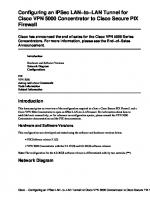
Cost and Time to Break (3)DES
Budget
40-Bit
56-Bit
168-Bit 3DES
Individual Hacker
$400
5 Hours
38 Years
Too Long
Dedicated Hacker
$10,000
12 Minutes
556 Days
1019 Years
$10m
0.02 Sec
21 Minutes
1017 Years
Type of Attacker
Intelligence Community
© 2003, Cisco Systems, Inc. All rights reserved.
ESAP DVS 2.0—2-1-25 1.0—2-1-23 1.0—1-1-23
Cost and Time to Break DES or 3DES The figure depicts the time needed to crack DES in 1996, depending on the attacker’s budget and key length. As the information portrays, 3DES is considered to be virtually impossible to break in the long term, and is expected to hold this status for many years to come.
Example Compare the relative strength of DES, 2-key 3DES, and 3-key 3DES: DES: 256 keys = 7.2 x 10¹⁶ key combinations 2-key 3DES: 2112 keys = 5.2 x 1033 combinations 3-key 3DES: 2168 keys = 3.7 x 1050 combinations
1-1-30
Designing VPN Security 1.0
Copyright © 2003, Cisco Systems, Inc.
3DES Usage Guidelines
• Three keying options defined for DES-EDE: – K1 = K2 = K3 – K1 and K2 are independent, but K1 = K3 – All three keys are independent • The first option makes 3DES backward compatible with DES. • Use three independent keys.
© 2003, Cisco Systems, Inc. All rights reserved.
ESAP DVS 2.0—2-1-26 1.0—2-1-24 1.0—1-1-24
Guidelines There are three keying options defined for DES-EDE: K1 = K2 = K3 K1 and K2 are independent, but K1 = K3 All three keys are independent The first option makes 3DES backward compatible with DES. Although 3DES with two keys is possible, always use three independent keys.
Copyright © 2003, Cisco Systems, Inc.
Encryption
1-1-31
Practice Q1)
Q2)
1-1-32
Which four modes can be used with DES? (Choose four.) A)
OBC
B)
ECB
C)
AES
D)
CBC
E)
CFB
F)
OFB
G)
3DES
What is the maximum key strength available with 3DES? A)
56-bit
B)
168-bit
C)
160-bit
D)
112-bit
E)
128-bit
Designing VPN Security 1.0
Copyright © 2003, Cisco Systems, Inc.
AES AES
• AES = Advanced Encryption Standard • AES initiative announced in 1997 to find an encryption standard to replace DES • There were rigorous reviews of fifteen original candidates • Final choice: the Rijndael ("Rain Doll") cipher
© 2003, Cisco Systems, Inc. All rights reserved.
ESAP DVS 2.0—2-1-27 1.0—2-1-25 1.0—1-1-25
Objective Upon completion of this section the learner will be able to describe the features and limitations of AES symmetric encryption algorithm.
Introduction The AES is the Advanced Encryption Standard. For a number of years it had been recognized that DES would eventually reach the end of its useful life. In 1997 the AES initiative was announced and the public was invited to propose candidate encryption schemes, one of which could be chosen as the encryption standard to replace DES.
AES Candidates There were fifteen original candidates (most were variants of existing popular algorithms), five candidates survived to the second round. They were: MARS: Submitted by IBM. Novel design. RC6: Submitted by RSA Laboratories. Based on RC5. Rijndael: Submitted by Daemen and Rijmen. Based on the “Square” algorithm. Serpent: Submitted by Anderson, Biham, and Knudsen. Copyright © 2003, Cisco Systems, Inc.
Encryption
1-1-33
Twofish: Submitted by Schneier, et al. Based on Schneier’s “Blowfish” algorithm.
1-1-34
Designing VPN Security 1.0
Copyright © 2003, Cisco Systems, Inc.
AES (Cont.)
• Rijndael cipher was developed by Joan Daemen and Vincent Rijmen • Variable block length and key length • Algorithm currently specifies how to use keys of length 128, 192 or 256 bits to encrypt blocks of length 128, 192 or 256 bits • Both block length and key length can be extended very easily to multiples of 32 bits
© 2003, Cisco Systems, Inc. All rights reserved.
ESAP DVS 2.0—2-1-28 1.0—2-1-26 1.0—1-1-26
The Rijndael Cipher On October 2, 2000, the U.S. National Institute of Standards and Technology (NIST) announced the selection of the Rijndael (“Rain Doll”) cipher as the Advanced Encryption Standard (AES) algorithm. The Rijndael cipher, developed by Joan Daemen and Vincent Rijmen, has a variable block length and key length. The algorithm currently specifies how to use keys with a length of 128, 192 or 256 bits to encrypt blocks with a length of 128, 192 or 256 bits (all nine combinations of key length and block length are possible). Both block length and key length can be extended very easily to multiples of 32 bits. The U.S. Secretary of Commerce approved the adoption of the AES as an official Government standard, effective May 26, 2002. Note
For more information on AES visit its official web site at http://www.nist.gov/aes or visit its author’s site at http://www.esat.kuleuven.ac.be/~rijmen/rijndael/.
Joan Daemen (Proton World International) and Vincent Rijmen (Katholieke Universiteit Leuven) submitted Rijndael. It is an iterated block cipher, meaning that the initial input block and cipher key undergoes multiple transformation cycles before producing the output. The algorithm can operate over a variable-length block using variable-length keys; a 128-, 192-, or 256-bit key can be used to encrypt data blocks that are 128, 192, or 256 bits long, and all nine combinations of key and block length are possible (the accepted AES implementation contains only some of Rijndael’s total capabilities). The algorithm is written so that block length and/or key length can easily be extended in multiples of 32 bits, and the system is specifically designed for efficient implementation in hardware or software on a range of processors.
Copyright © 2003, Cisco Systems, Inc.
Encryption
1-1-35
Rijndael is a substitution-linear transformation network with 10, 12 or 14 rounds, depending on the key size. A data block to be encrypted by Rijndael is split into an array of bytes, and each encryption operation is byte-oriented. Rijndael’s round function consists of four layers. In the first layer, an 8x8 S-box is applied to each byte. The second and third layers are linear mixing layers, in which the rows of the array are shifted, and the columns are mixed. In the fourth layer, subkey bytes are XORed into each byte of the array. In the last round, the column mixing is omitted.
AES vs. 3DES AES was chosen to replace DES and 3DES, as they are either too weak (DES, in terms of key length) or too slow (3DES) to run on modern, efficient hardware. AES is therefore more efficient (much faster, usually by a factor of around 5 compared to DES) on the same hardware, and is more suitable for high-throughput, low latency environments, especially if pure software encryption is used. However, AES is a relatively young algorithm, and, as the golden rule of cryptography states, a more mature algorithm is always more trusted. 3DES is therefore a more conservative and more trusted choice in terms of strength, as it has been analyzed for around 30 years.
AES Availability in the Cisco Product Line AES is available in the following Cisco VPN devices as an encryption transform, applied to IPSec-protected traffic Cisco IOS (from version 12.2(13)T on), Cisco PIX Firewall (from version 6.3on), Cisco VPN 3000 (from version 3.6 on).
Practice Q1)
Q2)
1-1-36
The algorithm chosen by the U.S. government as the AES is: A)
3DES
B)
Raindoll
C)
Rijndael
D)
RC6
True or false: The AES has a variable key length. A)
True
B)
False
Designing VPN Security 1.0
Copyright © 2003, Cisco Systems, Inc.
Rivest Ciphers (RC2/4/5/6) Rivest Ciphers (RC2/4/5/6) • RC2 (Ron’s Code 2): – Variable key-size block cipher designed as a “drop-in” replacement for DES • RC4: – Variable key-size stream cipher • RC5: – Fast block cipher with variables including block size and key size • RC6: – Block cipher based on RC5, one of AES Candidates © 2003, Cisco Systems, Inc. All rights reserved.
ESAP DVS 2.0—2-1-29 1.0—2-1-27 1.0—1-1-27
Objective Upon completion of this section the learner will be able to describe the features and limitations of RC4 symmetric encryption algorithm.
Introduction The RC family of algorithms is widely deployed in many networking applications because of their favorable speed and variable key length capabilities. This section briefly discusses their operation and compares them to other encryption algorithms.
RC Algorithms The “RC” (for “Ron’s Code” or “Rivest’s Cipher”) algorithms were designed all or in part by Ronald Rivest. Some of the most widely used are: RC2: Variable key-size block cipher designed as a “drop-in” replacement for DES. RC4: Variable key-size stream cipher. RC4 is often used in file encryption products and for secure communications, such as within the SSL protocol used for securing web site traffic. RC5: A fast block cipher with variables including block size and key size. With a 64-bit block size it can be used as a drop-in replacement for DES. Copyright © 2003, Cisco Systems, Inc.
Encryption
1-1-37
RC6: A block cipher based on RC5 designed by Rivest, Sidney, and Yin. Its main design goal was to meet the requirement of the AES.
1-1-38
Designing VPN Security 1.0
Copyright © 2003, Cisco Systems, Inc.
RC4
• Stream cipher • A variable key-size with byte-oriented operations • Can be expected to run very quickly in software • Commonly used for secure communications, as in the encryption of traffic to and from secure web sites using the SSL protocol
© 2003, Cisco Systems, Inc. All rights reserved.
ESAP DVS 2.0—2-1-30 1.0—2-1-28 1.0—1-1-28
RC4 RC4 is a variable key-size stream cipher with byte-oriented operations. The algorithm is based on the use of a random permutation. Analysts say that the period of the cipher is very largeprobably greater than 10100. Each output byte requires from 8 to 16 machine operations. The cipher can be expected to run very quickly in software. This algorithm is considered secure. RC4 is often used for file encryption. It is also commonly used for secure communications, as in the encryption of web site traffic using the SSL protocol.
Practice Q1)
Which RC algorithm is used to secure web transactions inside SSL? A)
3DES
B)
RC2
C)
RC3
D)
RC4
E)
RC5
F)
RC6
Copyright © 2003, Cisco Systems, Inc.
Encryption
1-1-39
RSA RSA
• Rivest, Shamir, Adelman (1977): – Patented, royalty • A public key cryptosystem. • Variable key length (usually 512-2048 bit): – Can trade speed for security • Based on the (current) difficulty of factoring very large numbers.
© 2003, Cisco Systems, Inc. All rights reserved.
ESAP DVS 2.0—2-1-31 1.0—2-1-29 1.0—1-1-29
Objective Upon completion of this section the learner will be able to describe the features and limitations of RSA asymmetric encryption algorithm.
Introduction Ron Rivest, Adi Shamir, and Len Adelman invented the RSA algorithm in 1977. It was a patented public-key algorithm. The patent expired in September, 2000, and the algorithm is now in the public domain. Of all the public-key algorithms proposed over the years, RSA is by far the easiest to understand and implement.
The RSA Algorithm The algorithm is very flexible as it has a variable key length, where, if necessary, speed can be traded for the security of the algorithm. The RSA keys are usually 512-2048 bits long. RSA has withstood years of extensive cryptanalysis and although they neither proved nor disproved RSA’s security, it does suggest a confidence level in the algorithm. RSA’s security is based on the difficulty of factoring very large numbers that is, breaking them into multiplicative factors. If an easy method of factoring these large numbers were discovered, the effectiveness of RSA would be destroyed.
1-1-40
Designing VPN Security 1.0
Copyright © 2003, Cisco Systems, Inc.
RSA Basics
• Each entity has two keys: – Public key (can be published) – Private key (must be kept secret) • It is not feasible to determine the private key from the public key. • One key encrypts, the other key decrypts a message. • Those keys are long-term (months/years).
© 2003, Cisco Systems, Inc. All rights reserved.
ESAP DVS 2.0—2-1-32 1.0—2-1-30 1.0—1-1-30
The RSA algorithm is based on the fact that each entity has two keys, a public key and a private key. The public key can be published and given away, but the private key must be kept very secret. It is not possible to determine the private key from the public key and vice versa by any computationally feasible algorithm. What one of those keys encrypts, the other key decrypts, and the other way around. RSA keys are long-term and are usually changed or renewed after some months or even years.
Copyright © 2003, Cisco Systems, Inc.
Encryption
1-1-41
RSA Algorithm—Key Generation
• Each entity generates two huge random primes p and q: – n = pq • Choose a huge number e, so that e and (p-1)(q-1) are relatively prime: – d = e-1 mod (p-1)(q-1) • The numbers (e, n) are the public key. • The number d is the private key.
© 2003, Cisco Systems, Inc. All rights reserved.
ESAP DVS 2.0—2-1-33 1.0—2-1-31 1.0—1-1-31
Key Generation To generate an entity’s RSA keys: 1. Select two very large prime numbers, p and q. 2. Compute n using the formula: n = p.q 3. Choose a huge prime e, with the constraint that e and (p-1)(q-1) are relatively prime. The public key is (e, n). 4. Calculate the private key d: e.d = 1(mod(p-1)(q-1)) In other words, d = e-1mod ((p-1)(q-1)) Note
1-1-42
d and n are also relatively prime. The numbers e and n are the public key; the number d is the private key. The two primes, p and q, are no longer needed. They should be discarded, but never revealed.
Designing VPN Security 1.0
Copyright © 2003, Cisco Systems, Inc.
RSA Algorithm—Encryption and Decryption
• RSA works on numeric blocks smaller than n. • Encryption of block P: – E = Pe mod n • Decryption of block E: – P = Ed mod n • Factoring n reveals both keys to the attacker, but is extremely difficult.
© 2003, Cisco Systems, Inc. All rights reserved.
ESAP DVS 2.0—2-1-34 1.0—2-1-32 1.0—1-1-32
Encryption and Decryption RSA works on numeric blocks smaller than n. To encrypt a message m, first the message must be divided into blocks smaller than n. If P is the plaintext block, it is then encrypted simply with the use of the formula: E=Pemod n To decrypt the message (where E is the ciphertext block), the following formula must be computed: P=Edmod n The message could just as easily have been encrypted with d and decrypted with e; the choice is arbitrary and depends on the security service to be provided. Factoring n reveals both keys to the attacker but it is extremely difficult, and when long enough keys are used, practically unfeasible.
Copyright © 2003, Cisco Systems, Inc.
Encryption
1-1-43
RSA Encryption Process
• Alice gets Bob’s public key • Alice encrypts message with Bob’s public key • Bob decrypts message using his private key © 2003, Cisco Systems, Inc. All rights reserved.
ESAP DVS 2.0—2-1-35 1.0—2-1-33 1.0—1-1-33
RSA Key Exchange for Encryption Providing privacy using encryption can be implemented using the RSA algorithm in the following way: Step 1
Alice wants to send a message to Bob, and this message needs to be kept confidential, so she obtains Bob’s public key.
Step 2
Alice uses Bob’s public key to encrypt the message with the RSA algorithm and sends the encrypted message to Bob.
Step 3
Bob decrypts the message using his private key, as it was encrypted using his public key. Because only Bob knows his private key, he is the only one capable of decrypting the message encrypted by his public key.
Therefore, encryption using the RSA algorithm is accomplished by:
1-1-44
Step 1
The sender encrypting the message using the receiver’s public key.
Step 2
The receiver decrypting the message using the receiver’s private key.
Designing VPN Security 1.0
Copyright © 2003, Cisco Systems, Inc.
RSA Usage Guidelines
• 100 (software) to 1000 (hardware) times slower than DES. • Used mainly for two services: – Privacy with encryption (usually small amounts of data such as session keys) – Authentication and non-repudiation with digital signing of data
© 2003, Cisco Systems, Inc. All rights reserved.
ESAP DVS 2.0—2-1-36 1.0—2-1-34 1.0—1-1-34
Guidelines RSA is about 100 times slower than DES in software, and about 1000 times slower in hardware. This performance problem is the main reason why RSA is usually only used to protect small amounts of data. RSA is mainly used for two services: 1. To ensure confidentiality of data by performing encryption. 2. To perform authentication/non-repudiation of data by generating digital signatures.
Note
Interestingly, RSA encryption is faster than decryption and verification is faster than signing.
Copyright © 2003, Cisco Systems, Inc.
Encryption
1-1-45
Choice of Encryption Algorithms • When choosing algorithms, there are two basic criteria: – The algorithm is trusted (scrutinized) by the cryptographic community – The algorithm provides enough protection against brute force attacks (key length) • With symmetric algorithms, DES, 3DES, IDEA, RC4 are considered trusted. • With asymmetric algorithms, RSA is considered trusted. • Other algorithms, such as ECC, are generally still immature in cryptographic terms. © 2003, Cisco Systems, Inc. All rights reserved.
ESAP DVS 2.0—2-1-37 1.0—2-1-35 1.0—1-1-35
Choosing an Algorithm Choosing the algorithm is obviously one of the key security issues when building a cryptography-based solution. There are two main criteria for selecting an encryption algorithm for an organization’s needs: The scrutiny and trust in the algorithm by the cryptographic community. Most new algorithms are broken very quickly, so algorithms, which have been resisting attacks for a number of years, are recommended. The benefits of new algorithms are often over-sold by their inventors and promoters, and the truth is that there are few or no revolutions in cryptography. The algorithm must provide enough protection against brute force attacks. If the algorithm is considered trusted, there is no shortcut to break it and the attacker must search through the keyspace to guess the correct key. The algorithm must allow key lengths, which satisfy an organization’s confidentiality requirements. DES, as an example, does not provide enough protection for most modern needs because of its short key. Based on the previous discussions about algorithm comparisons, a list of the current recommended algorithms follows. Symmetric encryption algorithms, which are considered trustworthy to provide confidentiality, include: DES (to protect data for a very short time due to the short key length) 3DES (a conservative choice, should be used to protect data when the highest strength and a very trusted algorithm are required) 1-1-46
Designing VPN Security 1.0
Copyright © 2003, Cisco Systems, Inc.
IDEA RC4 AES is a valid choice, being regarded as a good algorithm, although it is not proven to the degree 3DES is. Being more efficient, it can be used in high-throughput, low-latency environments, especially when 3DES cannot handle the throughput or latency requirements. In time, AES is expected to gain more and more trust, when more attacks are attempted at it. Of the asymmetric cryptographic algorithms, RSA is considered trustworthy for confidentiality.
Practice Q1)
Q2)
True or false: RSA is a symmetrical encryption public key algorithm. A)
True
B)
False
True or false: RSA’s security is based on the difficulty of factoring large numbers. A)
True
B)
False
Encryption using the RSA algorithm (or any public key system) is accomplished by: Q3)
The sender encrypting the message using the __________________.
Q4)
The receiver then decrypting the message using the __________________. A)
receiver’s private key
B)
receiver’s public key
C)
sender’s private key
D)
sender’s public key
Copyright © 2003, Cisco Systems, Inc.
Encryption
1-1-47
Summary This section summarizes the key points discussed in this lesson.
Summary
This lesson presented these key points: • What encryption is and why it is used. • Symmetric and asymmetric encryption algorithms and their differences. • Block and stream ciphers. • Pros and cons of common encryption methods.
© 2003, Cisco Systems, Inc. All rights reserved.
ESAP DVS 2.0—2-1-38 1.0—2-1-36 1.0—1-1-36
Next Steps After completing this lesson, go to: Hashing Algorithms lesson
References For additional information, refer to these resources: www.nist.gov/aes www.rsasecurity.com www.ssh.com/tech/crypto
1-1-48
Designing VPN Security 1.0
Copyright © 2003, Cisco Systems, Inc.
Quiz: Encryption Complete the quiz to assess what you have learned in this lesson.
Objectives This quiz tests your knowledge on how to: Describe the various encryption algorithms
Instructions Answer these questions: 1. What are the main differences between symmetric and asymmetric encryption techniques? 2. In the context of encryption, is the “avalanche effect” considered desirable? Why? 3. Which is typically a faster algorithm—asymmetric or symmetric? 4. What cryptographic algorithm has been chosen by the U.S. government as the standard to replace DES? 5. True or false: With 3DES, encrypting the data three times in a row using three different keys provides the best security.
Scoring You have successfully completed the quiz for this lesson when you earn a score of 80 percent or better.
Copyright © 2003, Cisco Systems, Inc.
Encryption
1-1-49
1-1-50
Designing VPN Security 1.0
Copyright © 2003, Cisco Systems, Inc.
Hashing Algorithms Overview Introduction This lesson provides an overview of the major hashing and Hash Message Authentication Code (HMAC) technologies that are widely used in modern computing and networking. It also describes some of the real-world implications of using various algorithms and technologies.
Importance Hashing and HMAC methods are used to provide data integrity and authenticity guarantees, when data might be exposed to untrusted parties. Understanding the basic mechanisms, and some of the tradeoffs involved in choosing a particular hashing/HMAC method, is important.
Lesson Objectives Upon completion of this lesson the learner will be able to describe the various hashing and HMAC algorithms, their features and limitations, and provide guidelines to an organizations on selecting the appropriate hash or HMAC algorithm.
Learner Skills and Knowledge To fully benefit from this lesson, you must have these prerequisite skills and knowledge: Describe the various encryption algorithms
Outline Outline
This lesson contains these sections: • Overview of Hash Algorithms and HMACs • MD5 • SHA-1
© 2003, Cisco Systems, Inc. All rights reserved.
1-2-2
Designing VPN Security 1.0
DVS 1.0—1-2-2
Copyright © 2003, Cisco Systems, Inc.
Overview of Hash Algorithms and HMACs Overview of Hash Algorithms and HMACs
• Used for integrity assurance. • Based on one-way functions. • Hash arbitrary data into a fixed length digest (fingerprint). • The digest is cryptographically strong: – Impossible to recover hashed data from digest – If data changes a little, the fingerprint changes a lot (avalanche effect)
© 2003, Cisco Systems, Inc. All rights reserved.
DVS 1.0—1-2-3
Objective Upon completion of this section the learner will be able to describe the purpose of hash and HMAC algorithms.
Introduction One of the mechanisms used for data integrity assurance is hashing. Hashing is based on a oneway mathematical function: functions that are relatively easy to compute, but significantly harder to reverse. Breaking a plate is a good example of a one-way function: it is easy to smash a plate into thousands of pieces, but almost impossible to put all the tiny pieces back together to re-build the original plate.
Hashing The hashing process uses a hash function, which is a one-way function of input data, to produce a fixed length digest (fingerprint) of output data. The digest is cryptographically very strong, that is, it is impossible to recover input data from its digest, and if the input data changes just a little bit, the digest (fingerprint) will change substantially (avalanche effect). Essentially, the digest (fingerprint) resulting from hashing some data uniquely identifies that data. Given only a fingerprint, it is computationally unfeasible to generate data that would result in such a digest. Hashing is often applied in the following situations
Copyright © 2003, Cisco Systems, Inc.
Hashing Algorithms
1-2-3
To generate one-time (and one-way) responses to challenges in authentication protocols (PPP CHAP, Microsoft NT Domain, EAP-MD5, and the like), To provide proof of integrity of data, such as with file integrity checkers (Tripwire is an example), or with document signing (digitally signed contracts, PKI certificates), To provide proof of authenticity (if used with a symmetric secret authentication key), such as with IPSec or routing protocol authentication.
1-2-4
Designing VPN Security 1.0
Copyright © 2003, Cisco Systems, Inc.
What Is a Hash Function?
Basic requirements for a cryptographic hash function: • The input can be any length • The output has a fixed length • H(x) is relatively easy to compute for any given x • H(x) is one-way • H(x) is collision-free
© 2003, Cisco Systems, Inc. All rights reserved.
DVS 1.0—1-2-4
Hash Functions A hash function, (H), is a transformation that takes an input (x), and returns a fixed-size string, which is called the hash value h. The formula used for the calculation is h = H(x). A cryptographic hash function should have the following general properties: Accepts input of any length Output has a fixed length H(x) is relatively easy to compute for any given x H(x) is one-way H(x) is collision-free A hash function, (H), is said to be one-way if it is hard to invert, where “hard to invert” means that given a hash value h, it is computationally infeasible to find some input, (x), such that H(x) = h. If, given a message x, it is computationally infeasible to find a message y not equal to x such that H(x) = H(y), then H is said to be a weakly collision-free hash function. A strongly collision-free hash function H is one for which it is computationally infeasible to find any two messages x and y such that: H(x) = H(y)
Copyright © 2003, Cisco Systems, Inc.
Hashing Algorithms
1-2-5
Hashing
The hashing process is not reversible © 2003, Cisco Systems, Inc. All rights reserved.
DVS 1.0—1-2-5
The figure illustrates how hashing is performed. Data of arbitrary length is input to the hash function, and the result of the hash function is the fixed length hash (digest, fingerprint). Hashing is similar to the calculation of Cyclic Redundancy Check (CRC) checksums, only that it is much stronger cryptographically. That is, given a CRC value, it is easy to generate data with the same CRC. However, with hash functions, this is computationally infeasible for an attacker.
1-2-6
Designing VPN Security 1.0
Copyright © 2003, Cisco Systems, Inc.
Hashing in Action
© 2003, Cisco Systems, Inc. All rights reserved.
DVS 1.0—1-2-6
The figure illustrates hashing in action. The sender wants to ensure that the message will not be altered on its way to the receiver. The sender uses the message as the input to a hashing algorithm and computes its fixed length digest or fingerprint. This fingerprint is then attached to the message (the message and the hash are in clear-text) and sent to the receiver. The receiver removes the fingerprint from the message and uses the message as input to the same hashing algorithm. If the hash computed by the receiver is equal to the one attached to the message, the message has not been altered during transit.
Copyright © 2003, Cisco Systems, Inc.
Hashing Algorithms
1-2-7
Hash Functions
Vulnerable to man-in-the-middle attacks: • Hashing does not provide security to transmission
Well known hash functions: • Message Digest 5 (MD5) with 128-bit hashes • Secure Hash Algorithm 1 (SHA-1) with 160-bit hashes
© 2003, Cisco Systems, Inc. All rights reserved.
DVS 1.0—1-2-7
There is no security added to the message in the previous example. Why? When the message traverses the network, a potential attacker could intercept the message, change it, recalculate the hash and append it to the message. Hashing only prevents the message from being changed accidentally (that is, by a communication error). There is nothing unique to the sender in the hashing procedure; therefore, anyone can compute a hash for any data, as long as they have the correct hash function. Thus, hash functions are helpful to ensure that data was not changed accidentally, but cannot ensure that data was not deliberately changed. Some well-known hash functions are: Message Digest 5 (MD5) with 128-bit digests Secure Hash Algorithm 1 (SHA-1) with 160-bit digests
1-2-8
Designing VPN Security 1.0
Copyright © 2003, Cisco Systems, Inc.
HMAC • Hash Message Authentication Code. • HMACs use an additional secret key as the input to the hash function. • The secret key is known to the sender and receiver: – Adds authentication to integrity assurance – Not vulnerable to man-in-the-middle attacks • Based on existing hash functions (keyed MD5, keyed SHA-1).
© 2003, Cisco Systems, Inc. All rights reserved.
DVS 1.0—1-2-8
HMAC Functions Hash functions are used as the basis of the HMACs protection mechanism. HMACs use existing hash functions, but with the significant difference of adding an additional secret key as the input to the hash function. Only the sender and the receiver know the secret key, and the output of the hash function now depends on the input data and the secret key. Therefore, parties who have access to that secret key can only compute the digest of an HMAC function. This defeats man-in-the-middle attacks and also provides authentication of data origin. If two parties share a secret key and use HMAC functions for authentication, a properly constructed HMAC digest of a message that a party has received indicates that the other party was the originator of the message, as it is the only other entity possessing the secret key. Some well-known HMAC functions are: Keyed MD5, based on the MD5 hashing algorithm Keyed SHA-1, based on the SHA-1 hashing algorithm
Copyright © 2003, Cisco Systems, Inc.
Hashing Algorithms
1-2-9
HMAC (Cont.)
Same procedure is used for generation and verification of secure fingerprints © 2003, Cisco Systems, Inc. All rights reserved.
DVS 1.0—1-2-9
The figure illustrates how an HMAC digest is created. Data of an arbitrary length is input to the hash function, together with a secret key. The result is the fixed length hash that depends not only on the data, but also on the secret key.
1-2-10
Designing VPN Security 1.0
Copyright © 2003, Cisco Systems, Inc.
HMACs in Action
© 2003, Cisco Systems, Inc. All rights reserved.
DVS 1.0—1-2-10
The figure illustrates HMACs in action. The sender wants to ensure that the message cannot be altered on its way to the receiver, and also wants the receiver to be sure about the origin of the message (authentication). The sender takes the data and the secret key, uses a hashing algorithm, and calculates the fixed length HMAC digest or fingerprint. This authenticated fingerprint is then attached to the message and sent to the receiver. The receiver removes the fingerprint from the message and uses the message with the secret key as input to the same hashing function. If the fingerprint calculated by the receiver is equal to the sent fingerprint, the message has not been altered during transit (this is ensured by the properties of hash functions) and the origin of the message is authenticated, as only the sender possesses the shared secret key.
Example IPSec VPNs rely on HMAC functions to authenticate every packet’s origin and provide data integrity.
Usage of Hashing in Cisco Product Line Cisco products use hashing for entity authentication, data integrity, and data authenticity purposes: IPSec gateways and clients use hashing (MD5 and SHA-1 in HMAC mode) to provide packet integrity and authenticity, Cisco IOS routers use hashing (again, with secret keys in a HMAC-like manner) to add authentication information to routing protocol updates,
Copyright © 2003, Cisco Systems, Inc.
Hashing Algorithms
1-2-11
Cisco software images downloadable from the CCO have a MD5-based checksum available on the CCO site for customers to check the integrity of downloaded images, Hashing can also be used in a feedback-like mode to encrypt data (i.e. a hash algorithm can act as an encryption algorithm). For example, TACACS+ encrypts its session with MD5.
Practice Q1)
1-2-12
What is true about the output of a cryptographic hash function? A)
It is of fixed length
B)
It is of any length
C)
It is infeasible to compute
D)
It is combined with a secret key to yield a HMAC
E)
It takes significant computational effort to compute
Designing VPN Security 1.0
Copyright © 2003, Cisco Systems, Inc.
MD5 MD5 • Ubiquitous hashing algorithm. • Hashing properties: – One-way function—easy to compute hash, infeasible to compute data given a hash – Collision resistant—two messages with same hash are very unlikely • MD5 is a complex sequence of simple binary operations (XORs, rotations, etc.) which finally produces a 128-bit hash.
© 2003, Cisco Systems, Inc. All rights reserved.
DVS 1.0—1-2-11
Objective Upon completion of this section the learner will be able to describe the characteristics of MD5.
Introduction The MD5 algorithm is a ubiquitous hashing algorithm, developed by Ron Rivest, and used in a variety of Internet applications today.
MD5 Definition The MD in its name stands for message digest, and, as the name suggests, MD5 is a one-way function with which it is easy to compute a hash from the given input data, but unfeasible to compute input data given only a hash. MD5 is also collision resistant, which means that two messages with the same hash are very unlikely to occur. MD5 is essentially a complex sequence of simple binary operations (XORs, rotations, etc.) on input data, which finally produces a 128-bit digest.
Copyright © 2003, Cisco Systems, Inc.
Hashing Algorithms
1-2-13
MD5 (Cont.)
• Based on a compression function: – Operates on blocks – Input is a data block plus a feedback of previous outputs • Message length is encoded into the digest. • Not recommended for new applications. • SHA-1 is preferred for highest security.
© 2003, Cisco Systems, Inc. All rights reserved.
DVS 1.0—1-2-12
The main algorithm itself is based on a compression function, which operates on blocks. Input is a data block plus a feedback of previous blocks. 512-bit blocks are divided into 16 32-bit sub-blocks. These blocks are then rearranged with simple operations in a main loop, which consists of 4 rounds. The output of the algorithm is a set of 4 32-bit blocks, which concatenate to form a single 128-bit hash value. The message length is also encoded into the digest. MD5 is based on an earlier algorithm, MD4. MD4 has been broken, and MD5, at the time of this writing (June, 2002), is considered less secure than SHA-1 by some authorities on cryptography. The reason behind it is that some non-critical weaknesses have been found in one of the MD5 building blocks, which has caused uneasy feelings inside the cryptographic community. The availability of the SHA-1 and RipeMD-160 hash/HMAC functions, which do not show such weaknesses, and use a stronger, 160-bit digest, makes MD5 a second choice as far as hash methods are concerned.
Practice Q1)
1-2-14
What is the length of MD5 output (hash)? A)
64 bits
B)
128 bits
C)
160 bits
D)
168 bits
E)
256 bits
Designing VPN Security 1.0
Copyright © 2003, Cisco Systems, Inc.
SHA-1 SHA-1
• Similar design to MD4/5 family of hash functions: – Takes an input message of no less than 264 bits long – Produces a 160-bit message digest • Algorithm is slightly slower than MD5. • SHA-1 is a revision that corrected an unpublished flaw in the original SHA.
© 2003, Cisco Systems, Inc. All rights reserved.
DVS 1.0—1-2-13
Objective Upon completion of this section the learner will be able to describe the characteristics of SHA.
Introduction The U.S. National Institute of Standards and Technology (NIST) developed the SHA, the algorithm specified in the Secure Hash Standard (SHS). SHA-1 is a revision to the SHA that was published in 1994; the revision corrected an unpublished flaw in SHA. Its design is very similar to the MD4 family of hash functions developed by Rivest.
The SHA-1 Algorithm The algorithm takes a message of no less than 264 bits in length and produces a 160-bit message digest. The algorithm is slightly slower than MD5, but the larger message digest makes it more secure against brute-force collision and inversion attacks. The official standard text can be found at http://www.itl.nist.gov/fipspubs/fip180-1.htm.
Copyright © 2003, Cisco Systems, Inc.
Hashing Algorithms
1-2-15
MD5 and SHA-1 Compared
• Both derived from MD4 • SHA-1 digest is 32 bits longer • MD5 vulnerable to cryptanalytic attack, but not critically • SHA-1 should be slower on same hardware • Both are simple to describe and implement
© 2003, Cisco Systems, Inc. All rights reserved.
DVS 1.0—1-2-14
Since both algorithms are based on MD4 (which has been broken), MD5 and SHA-1 are very similar. SHA-1 should be more resistant to brute force attacks since its digest is 32 bits longer than the MD5 digest. SHA-1 involves 80 steps versus 64 steps for MD5. The SHA-1 algorithm must also process a 160-bit buffer versus MD5’s 128-bit buffer. Therefore, it is expected that, given the same hardware, MD5 would execute more quickly. In general, when given a choice, SHA-1 is the preferred hash algorithm. MD5 is arguably less trusted today, and for most commercial environments, such risks should be avoided.
1-2-16
Designing VPN Security 1.0
Copyright © 2003, Cisco Systems, Inc.
Hash/HMAC Guidelines
• Avoid MD5 if possible • Use stronger SHA-1 or RIPEMD-160 • If speed is an issue, perhaps consider MD5 • Protect HMAC secret keys!
© 2003, Cisco Systems, Inc. All rights reserved.
DVS 1.0—1-2-15
Guidelines When choosing a hashing algorithm, SHA-1 is generally preferred over MD5. MD5 has not been proven to contain any critical flaws, but its security is questionable today. MD5 might be considered if performance is an issue, as it might increase performance slightly, but not substantially. However, the risk exists that it might be discovered to be substantially weaker than SHA-1. With HMACs, care must be taken to only distribute secret keys to the parties involved, as compromise of the secret key enables any other party to forge and/or change packets and therefore violate data integrity.
Copyright © 2003, Cisco Systems, Inc.
Hashing Algorithms
1-2-17
MD5 Used as a HMAC hostname hostname R1 R1 !! interface interface Ethernet0 Ethernet0 ip ip address address 150.50.15.1 150.50.15.1 255.255.255.0 255.255.255.0 ip ip ospf ospf authentication authentication message-digest message-digest ip ip ospf ospf message-digest-key message-digest-key 11 md5 md5 hello hello !! router router ospf ospf 11 network network 150.50.15.1 150.50.15.1 0.0.0.0 0.0.0.0 area area 00 hostname hostname R2 R2 !! interface interface Ethernet0 Ethernet0 ip ip address address 150.50.15.2 150.50.15.2 255.255.255.0 255.255.255.0 ip ip ospf ospf authentication authentication message-digest message-digest ip ip ospf ospf message-digest-key message-digest-key 11 md5 md5 hello hello !! router router ospf ospf 11 network network 150.50.15.2 150.50.15.2 0.0.0.0 0.0.0.0 area area © 2003, Cisco Systems, Inc. All rights reserved.
DVS 1.0—1-2-16
MD5 Example The figure illustrates portions of configurations for two Cisco routers. Each router has an Ethernet0 interface in OSPF Area 0. The routers have been configured to use MD5 for authentication of OSPF packets. When the transmitting router wants to send an OSPF packet, the MD5 algorithm computes a hash using the contents of the OSPF packet and the password (“hello” in this case). The hash value is included in the transmitted OSPF packet, along with some other information. When it receives the packet, the receiver calculates its own hash value. If the message has not changed, the hash value contained in the packet should match the hash computed by the receiver. The receiver’s OSPF process will then accept that packet.
1-2-18
Designing VPN Security 1.0
Copyright © 2003, Cisco Systems, Inc.
SHA-1 Used As a HMAC hostname hostname pix1 pix1 crypto crypto ipsec ipsec transform-set transform-set r4 r4 esp-des esp-des esp-sha-hmac esp-sha-hmac crypto crypto map map r4 r4 10 10 set set transform-set transform-set r4 r4 isakmp isakmp policy policy 10 10 encryption encryption des des isakmp isakmp policy policy 10 10 hash hash sha sha hostname hostname r4 r4 !! crypto crypto isakmp isakmp policy policy 10 10 hash hash sha sha !! crypto crypto ipsec ipsec transform-set transform-set pix1 pix1 esp-des esp-des esp-sha-hmac esp-sha-hmac !! crypto crypto map map pix1 pix1 10 10 ipsec-isakmp ipsec-isakmp set set transform-set transform-set pix1 pix1
© 2003, Cisco Systems, Inc. All rights reserved.
DVS 1.0—1-2-17
SHA-1 Example In the example, router “r4” and Cisco PIX firewall “pix1” have been configured to use IPSec for communications between them. The slide illustrates portions of the IPSec configurations for r4 and pix1. The PIX and the router are configured to use DES (des) and HMAC-SHA-1 (sha) for their pre-shared key exchange using Internet Security Association & Key Management Protocol (ISAKMP). The actual data packets to be exchanged between r4 and pix1 are protected by transform sets that use DES for packet payload encryption (esp-des) and HMACMD5 for packet authentication (esp-md5-hmac). Note
The default ISAKMP settings for the router r4 include DES encryption and SHA-1 hashing, however default parameters usually do not appear in a Cisco router configuration.
Practice Q1)
What is the length of SHA-1 output (hash)? A)
64 bits
B)
128 bits
C)
160 bits
D)
168 bits
E)
256 bits
Copyright © 2003, Cisco Systems, Inc.
Hashing Algorithms
1-2-19
Summary This section summarizes the key points discussed in this lesson.
Summary This lesson presented these key points: • Hash algorithms are widely used for data integrity. • A hash function is a one-way function with a fixed-length output. • The hashing process is not reversible. • Hash functions help to ensure data has not changed accidently, but cannot ensure that data was deliberately changed. • HMACs are message digests that depend not only on the data, but also on a secret key. • HMACs can authenticate packet origin and also provide data integrity. © 2003, Cisco Systems, Inc. All rights reserved.
DVS 1.0—1-2-18
Next Steps After completing this lesson, go to: Digital Signatures lesson
References For additional information, refer to these resources: Security Requirements for Keys used with the TCP MD5 Signature Option, http://www.ietf.org/internet-drafts/draft-ietf-idr-md5-keys-00.txt
1-2-20
Designing VPN Security 1.0
Copyright © 2003, Cisco Systems, Inc.
Quiz: Hashing Algorithms Complete the quiz to assess what you have learned in this lesson.
Objectives This quiz tests your knowledge on how to: Describe the hashing algorithms Describe how hash algorithms are used to create cryptographically stronger HMACs
Instructions Answer these questions: 1. What are the properties of a cryptographic hash algorithm? 2. What vulnerabilities do HMACs address? 3. List some differences between MD5 and SHA-1 algorithms.
Scoring You have successfully completed the quiz for this lesson when you earn a score of 80 percent or better.
Copyright © 2003, Cisco Systems, Inc.
Hashing Algorithms
1-2-21
1-2-22
Designing VPN Security 1.0
Copyright © 2003, Cisco Systems, Inc.
Digital Signatures Overview Introduction This lesson provides an overview of the digital signature technologies that are widely used in modern computing and networking. It also describes some of the real-world implications of using various algorithms and technologies.
Importance Digital signature methods are used to provide guarantees of data integrity and authenticity, and guarantees of transaction non-repudiation, when data might be exposed to untrusted parties. Understanding the basic mechanisms, and some of the tradeoffs involved in choosing a particular digital signature method, is important.
Lesson Objectives Upon completion of this lesson the learner will be able to describe the signing process using RSA or DSS signatures.
Learner Skills and Knowledge To fully benefit from this lesson, you must have these prerequisite skills and knowledge: Describe the various encryption algorithms Describe the hashing algorithms Describe how hash algorithms are used to create cryptographically stronger HMACs
Outline Outline
This lesson contains these sections: • Overview of Signature Algorithms • RSA • DSS
© 2003, Cisco Systems, Inc. All rights reserved.
1-3-2
Designing VPN Security 1.0
DVS 1.0—1-3-2
Copyright © 2003, Cisco Systems, Inc.
Overview Overview This lesson describes digital signatures and show how they can help solve these problems: • How to know if documents have changed? • How to prevent distribution of fraudulent documents? • How to prevent people from changing your words? • How to prove that you are the original author of a document?
© 2003, Cisco Systems, Inc. All rights reserved.
DVS 1.0—1-3-3
When data is exchanged over untrusted networks, several major security issues need to be addressed How does one know if data has changed in transit? Hashing/HMAC functions might provide integrity guarantees, but rely on a cumbersome exchange of secret keys between parties. How does one know if a document is authentic? Hashing/HMAC can again provide some guarantee of authenticity, but only using secret keys and only between two parties. How do we prove the authenticity of a transaction or a document to a third party? Digital signatures are often applied in the following situations To provide a unique proof of data source, which can be only generated by a single party (contract signing in e-commerce environments), To authenticate users using a user’s private key (and the signature it generates) as the authenticator, PKI certificates are issued with the digital signature providing the proof of their authenticity and integrity, To provide secure time stamping – a central trusted time source propagates time information, digitally signed by the originator.
Copyright © 2003, Cisco Systems, Inc.
Digital Signatures
1-3-3
Example Suppose a customer sends transaction instructions via an email to a stockbroker, and the transaction turns out badly for the customer. It is conceivable that the customer could claim never to have sent the transaction order, or that someone forged the email. The brokerage could protect itself by requiring the use of digital signatures before accepting instructions via email.
1-3-4
Designing VPN Security 1.0
Copyright © 2003, Cisco Systems, Inc.
Overview of Signature Algorithms Overview of Digital Signatures • Digital signatures provide three security services in secure communications: – Data authenticity – Data integrity – Non-repudiation of transactions • Already equivalent to normal signatures in some countries • Usually asymmetric algorithms are used (RSA, DSA)
© 2003, Cisco Systems, Inc. All rights reserved.
DVS 1.0—1-3-4
Objective Upon completion of this section the learner will be able to describe the general process of signing using digital signatures.
Introduction Handwritten signatures have long been used as a proof of authorship of, or at least agreement with, the contents of a document. Digital signatures can provide the same functionality as handwritten signatures, and much more.
Digital Signature Properties Digital signatures provide three basic security services in secure communications Authenticity of digitally signed data, i.e. authentication of source, proving that a certain party has seen has signed the data in question Integrity of digitally signed data, which guarantees, that the data has not changed since being signed by the signer Non-repudiation of the transaction—the recipient can take the data to a third party, which will accept the digital signature as a proof that this data exchange really did take place. The signing party cannot repudiate (i.e. deny) that it has signed the data. Copyright © 2003, Cisco Systems, Inc.
Digital Signatures
1-3-5
Note
To better understand non-repudiation, consider using HMAC functions, which also provide authenticity and integrity guarantees, instead. With HMACs, TWO (or more) parties share the same authentication key, and can compute the HMAC fingerprint. Therefore, taking received data and its HMAC fingerprint to a third party does not provide any proof that the other party has sent this data, as you might have generated the same HMAC fingerprint yourself, having the HMAC authentication key. With digital signatures, each party has a unique, secret signature key, which is not shared with any other party, making nonrepudiation possible.
To achieve the above goals, the properties of a digital signature are: The signature is authentic: The signature convinces the recipient of the document that the signer signed the document. The signature is unforgeable: The signature is proof that the signer, and no one else, signed the document. The signature is not reusable: The signature is a part of the document and cannot be moved to a different document. The signature is unalterable: After a document is signed it cannot be altered. The signature cannot be repudiated: The signature and the document are physical things. The signer cannot claim later that they did not sign it. Well-known asymmetric algorithms, such as RSA or DSA, are usually used to perform digital signing.
Legal Implications of Digital Signatures In come countries and US states, digital signatures are already considered equivalent to handwritten signatures, if certain provisions are met, such as proper protection of the certificate authority (the trusted signer of all other public keys), and the proper protection of the users’ private keys. In such a scenario, users are responsible for keeping their private keys private, as a stolen private key can be used to “steal” someone’s identity.
1-3-6
Designing VPN Security 1.0
Copyright © 2003, Cisco Systems, Inc.
Digital Signatures in Action
© 2003, Cisco Systems, Inc. All rights reserved.
DVS 1.0—1-3-5
The figure illustrates how digital signatures work: Step 1
When someone wants to sign some data, they use a signature algorithm with their signature key. This signature key is only known to the signer and therefore must be kept secret.
Step 2
Based on the input data and a signature key, the signature algorithm generates its output, which is called a digital signature.
Step 3
The sender then attaches the digital signature to the message and sends the message to the receiver.
Step 4
The receiver verifies the signature with the verification key, which is usually public.
Step 5
The receiver inputs the message, the digital signature, and the verification key to the verification algorithm, which checks the validity of the digital signature.
Step 6
If the check is successful, the document has not been changed after signing and the signer of the document originated the document.
Copyright © 2003, Cisco Systems, Inc.
Digital Signatures
1-3-7
Digital Signature Example
Digital signatures are widely used for code signing: • The publisher of software attaches a digital signature to the executable, signed with the publisher’s signature key • The user of software needs to obtain the publisher’s public key (or the CA certificate, if using PKI) © 2003, Cisco Systems, Inc. All rights reserved.
DVS 1.0—1-3-6
Example Digital signatures are widely used today to provide assurance of mobile (and classic software) code authenticity and integrity. The executable files (or perhaps the whole installation package of a program) are wrapped with a digitally signed envelope, which allows the end user to verify the signature before installing the software. Digitally signing code provides assurance that the code: Has not been modified since it has left the software publisher Is authentic and actually sourced by the publisher Was undeniably published by the publisher (non-repudiation of the act of publishing) The digital signature could only be forged if someone obtained the publisher’s private key. If the private key is protected properly, the assurance level of digital signatures is extremely high. The user of the software must also somehow obtain the public (verification) key, which is used to verify the signature. This key can be obtained in a secure fashion (for example, included with the installation of the operating system), or transferred securely over the network, for example, using the Public Key Infrastructure and certificate authorities.
1-3-8
Designing VPN Security 1.0
Copyright © 2003, Cisco Systems, Inc.
Practice Q1)
Q2)
What are the three properties of digital signatures? (Choose three.) A)
Signatures guarantee authenticity of data
B)
Signatures should be unforgeable
C)
Signatures provide confidentiality of signed data
D)
Signatures provide key exchange
E)
Signed data cannot be repudiated
Is a digital signature verification key usually public or private? A)
Public
B)
Private
Copyright © 2003, Cisco Systems, Inc.
Digital Signatures
1-3-9
RSA RSA
• Alice encrypts message with her private key • Bob gets Alice’s public key • Bob decrypts message using Alice’s public key © 2003, Cisco Systems, Inc. All rights reserved.
DVS 1.0—1-3-7
Objective Upon completion of this section the learner will be able to describe the RSA implementation of digital signatures.
Introduction The RSA algorithm is the most ubiquitous method for signature generation today, and is used widely in e-commerce systems and Internet protocols in that role. RSA signing is a process, which is a reverse of RSA encryption.
RSA Signature Overview Providing authentication and non-repudiation using digital signatures with the RSA algorithm is accomplished in the following way:
1-3-10
Step 1
Alice wants to sign her message to Bob, so she uses her private key to encrypt the message.
Step 2
Alice sends the message to Bob, who obtains her public key and decrypts the message.
Step 3
The signature is verified, if the message decrypts properly. Only the owner of Alice’s private key can encrypt the message in such a way that using her public key can decrypt the message. Because only Alice has her private key, the originator of the message must be Alice.
Designing VPN Security 1.0
Copyright © 2003, Cisco Systems, Inc.
Therefore, encryption using the RSA algorithm is accomplished by: Step 1
The sender encrypting the message using the receiver’s public key.
Step 2
The receiver decrypting the message using the receiver’s private key.
Example Of course, one has to trust that the public key is legitimate. Suppose Mary wants to cause some mischief between Alice and Bob. Mary could pretend to be Alice and send a public key to Bob. Bob thinks he has Alice’s key. Mary (as Alice) could send digitally signed messages to Bob and because “Alice’s” public key verifies the messages he could be fooled.
Copyright © 2003, Cisco Systems, Inc.
Digital Signatures
1-3-11
RSA Digital Signatures in Detail Digital signatures based on PK algorithms also involve hashing
© 2003, Cisco Systems, Inc. All rights reserved.
DVS 1.0—1-3-8
Signing Process in Detail The signing procedures of digital signatures, as they are used today, are not simply implemented by public key operations. In fact, a modern digital signature would be based on a hash function and a public-key algorithm. The procedure is illustrated in the figure. The signature process is as follows: Step 1
The signer makes a hash (fingerprint) of the document, which uniquely identifies the document and all its contents.
Step 2
The signer encrypts the hash only with the signer’s private key.
Step 3
The encrypted hash (the “signature”) is appended to the document.
The verification process works as follows: Step 1
The verifier obtains the signer’s public key.
Step 2
The verifier decrypts the signature with the signer’s public key. This unveils the assumed signer’s hash value.
Step 3
The verifier makes a hash of the received document (without its signature) and compares this hash to the decrypted signature hash. If the hashes match, the document is authentic (that is, it has been signed by the assumed signer) and has not been changed since the signer signed it.
This example illustrates how the authenticity and integrity of the message is ensured, even though the actual text is public. Both encryption and digital signatures are required to ensure that the message is private and has not been changed.
1-3-12
Designing VPN Security 1.0
Copyright © 2003, Cisco Systems, Inc.
Practice Q1)
Q2)
What are the two main pieces of a modern digital signature? (Choose two.) A)
Hash function
B)
Encryption function
C)
Public-key algorithm
D)
HMAC function
E)
Compression function
What are the three main steps involved in the digital signature process? (Choose three.) A)
Signer makes a hash of the document
B)
Signer encrypts the document
C)
Signer encrypts the hash with the signer’s private key
D)
Verifier decrypts the hash with the signer’s private key
E)
Encrypted hash is appended to document
Copyright © 2003, Cisco Systems, Inc.
Digital Signatures
1-3-13
DSS DSS
Digital Signature Standard (DSS): • First issued in 1994 by NIST. • Digital authentication standard of U.S. government. • Initial standard specified only Digital Signature Algorithm (DSA). • Two algorithms added to DSS since then: – Digital Signature Using Reversible Public Key Cryptography (an RSA signature algorithm) – Elliptic Curve Digital Signature Algorithm (ECDSA)
© 2003, Cisco Systems, Inc. All rights reserved.
DVS 1.0—1-3-9
Objective Upon completion of this section the learner will be able to describe the DSS implementation of digital signatures.
Introduction In 1994, the U.S. National Institute of Standards and Technology (NIST) selected the Digital Signature Algorithm (DSA) as the Digital Signature Standard (DSS). DSA is based on the “discrete logarithm problem” and can only be used to provide digital signatures.
The DSA Algorithm and its Relationship to DSS Signature generation in DSA is faster than signature verification, whereas with the RSA algorithm, signature verification is very much faster than signature generation. Criticisms of DSA were: It lacked the flexibility of RSA Verification of signatures was too slow The process by which NIST chose DSA was too secretive and arbitrary (too much influence by the NSA)
1-3-14
Designing VPN Security 1.0
Copyright © 2003, Cisco Systems, Inc.
In response to these criticisms, the DSS now incorporates two additional algorithm choices: Digital Signature Using Reversible Public Key Cryptography (which uses RSA) Elliptic Curve Digital Signature Algorithm (ECDSA)
Copyright © 2003, Cisco Systems, Inc.
Digital Signatures
1-3-15
DSS (Cont.)
The Current DSS Choices: • Digital Signature Algorithm (DSA): – A variant of the ElGamal signature scheme – Discrete logarithms • Digital Signature Using Reversible Public Key: – RSA as specified in ANSIX9.31 • Elliptic Curve Digital Signature Algorithm (ECDSA): – Elliptic Curve DSA as specified in ANSIX9.62 – Elliptic curve analog of the DSA
© 2003, Cisco Systems, Inc. All rights reserved.
DVS 1.0—1-3-10
DSA is based on the “Discrete Logarithm Problem”. Taher El-Gamal was the first to propose a public-key cryptosystem based on this problem: Fix a prime number p. Then, given an integer g between 0 and p-1, and y, which is the result of exponentiating g, the following relation between g and y is: y = gx (mod p) for some x. The discrete logarithm problem, modulo p, is to determine the integer x for a given pair g and y. Similar to the integer factorization problem used as the basis for RSA, no efficient algorithm is known to solve the discrete logarithm problem, modulo p. The Elliptic Curve Cryptosystem (ECC) can be used to provide both a digital signature scheme and an encryption scheme. The security of the ECC rests on the difficulty of the elliptic curve discrete logarithm problem. As with the integer factorization problem (RSA) and the discrete logarithm problem, modulo p, no efficient algorithm is known that can solve the elliptic curve discrete logarithm problem. The elliptic curve discrete logarithm problem is believed by some to be harder than both the integer factorization problem and the discrete logarithm problem, modulo p. In other words, ECC could be the strongest public-key cryptographic system currently known.
1-3-16
Designing VPN Security 1.0
Copyright © 2003, Cisco Systems, Inc.
Digital Signature Guidelines • Always provide extremely strong protection of the private (signature) key: – Otherwise, there is no non-repudiation • Use the PKI to scale applications of digital signatures. • RSA versus DSA: – DSA signature generation faster than signature verification – RSA signature verification very much faster than signature generation – What do you do most often? Sign or verify? © 2003, Cisco Systems, Inc. All rights reserved.
DVS 1.0—1-3-11
Guidelines Protection of the private (signature) key is of the highest importance when using digital signatures. If the signature key of an entity is compromised, the attacker can sign data in that entities’ name and repudiation is not possible. To exchange verification keys scalably, a Public Key Infrastructure (PKI) needs to be deployed in most scenarios. To compare the RSA and DSA algorithms: DSA signature generation is faster than signature verification RSA signature verification is very much faster than signature generation
Usage of Digital Signatures in Cisco Product Line Cisco products use digital signatures for entity authentication, data integrity, and data authenticity purposes: IPSec gateways and clients use digital signatures to authenticate their IKE sessions, if digital certificates and the IKE “RSA signature” authentication method are chosen, Cisco SSL endpoints (Cisco IOS HTTP server, various management interfaces, such as the PIX Device Manager) use digital signatures to prove the identity of the SSL server, Some of the service-provider oriented voice management protocols (for billing and settlement) use digital signatures to authenticate the involved parties. Copyright © 2003, Cisco Systems, Inc.
Digital Signatures
1-3-17
Practice Q1)
Q2)
Q3)
1-3-18
What are the three algorithms currently specified within the DSS? (Choose three.) A)
DSA
B)
HMAC
C)
RSA
D)
MD5
E)
ECDSA
F)
3DES
Which has faster signature verification—DSA or RSA? A)
DSA
B)
RSA
Which has faster signature generation—DSA or RSA? A)
DSA
B)
RSA
Designing VPN Security 1.0
Copyright © 2003, Cisco Systems, Inc.
Summary This section summarizes the key points discussed in this lesson.
Summary This lesson presented these key points: • Digital signatures are used for authentication and nonrepudiation. • Digital signatures usually use asymmetric (public-key), algorithms along with a hash function. • Some of the common digital signature schemes are: – RSA – DSA – ECDSA • Some algorithms sign faster than others. • Some algorithms verify faster than others.
© 2003, Cisco Systems, Inc. All rights reserved.
DVS 1.0—1-3-12
Next Steps After completing this lesson, go to: Key Management module, Key Generation and Storage lesson
References For additional information, refer to these resources: Frequently Asked Questions on modern cryptography, http://www.rsasecurity.com/rsalabs/faq An overview of various signature technologies, http://www.ssh.com/tech/crypto A description of DSS, http://csrc.nist.gov/cryptval/dss
Copyright © 2003, Cisco Systems, Inc.
Digital Signatures
1-3-19
Quiz: Digital Signatures Complete the quiz to assess what you have learned in this lesson.
Objectives This quiz tests your knowledge on how to: Describe how digital signatures operate Explain the digital signing process using RSA and DSS signatures
Instructions Answer these questions: 1. What are the two main pieces to a digital signature? 2. What are the three algorithms currently specified within the DSS? 3. Name at least three desirable properties of digital signatures. 4. Name the steps used to sign/verify a digital signature.
Scoring You have successfully completed the quiz for this lesson when you earn a score of 80 percent or better.
1-3-20
Designing VPN Security 1.0
Copyright © 2003, Cisco Systems, Inc.
Key Generation and Storage Overview Introduction Key management is often considered the most difficult task in designing and implementing cryptographic systems. Inside key management, key generation and storage are two of the most important factors, which determine the strength of the system. This lesson introduces techniques and guidelines for designing and implementing key generation and storage mechanisms into cryptographic systems.
Importance The keys used in encryption are vital parts of the technology. Choosing the correct key lengths and the generation mechanisms are both important because so much depends on the keys. It is also necessary to store the keys securely and reliably so that they are safe but fairly easy to use.
Lesson Objectives Upon completion of this lesson the learner will be able to list and describe the options for generating keys, recommend the storage media that can be used to store cryptographic keys, and name the guidelines for generating cryptographically strong keys.
Learner Skills and Knowledge To fully benefit from this lesson, you must have these prerequisite skills and knowledge: Describe the various encryption algorithms Describe the hashing algorithms Describe how hash algorithms are used to create cryptographically stronger HMACs Describe how digital signatures operate Explain the digital signing process using RSA and DSS signatures
Outline Outline This lesson contains these sections: • • • • • • •
Key Management Manual Key Generation Key Generation Using Random Numbers Natural Sources of Randomness Key Storage in Memory Key Storage in Non-Volatile Memory Key Storage on Smart Cards
© 2003, Cisco Systems, Inc. All rights reserved.
2-1-2
Designing VPN Security 1.0
DVS 1.0—2-1-2
Copyright © 2003, Cisco Systems, Inc.
Key Management What is Key Management? • Key management deals with the secure generation, verification, exchange, storage, and destruction of keys. • Often considered the most difficult task when designing cryptographic systems. • Secure methods of key management are extremely important. • In practice, most attacks on cryptographic systems will probably be aimed at the key management level, rather than at the cryptographic algorithm itself. © 2003, Cisco Systems, Inc. All rights reserved.
DVS 1.0—2-1-3
Objective Upon completion of this section the learner will be able to explain the purpose and importance of key management within cryptographic systems, and recommend key lengths for an organization’s requirements.
Introduction Key management is often considered to be the most difficult part when designing a cryptosystem. Many cryptosystems have failed due to mistakes in their key management, and all modern cryptographic algorithms require the services of key management procedures. In practice, most attacks on cryptographic systems will probably be aimed at the key management level, rather than at the cryptographic algorithm itself.
Key Management Components Key management consists of: Key generation Key verification Key storage
Copyright © 2003, Cisco Systems, Inc.
Key Generation and Storage
2-1-3
Key exchange Key revocation/destruction In a modern cryptographic system, key generation is usually automated and not left to the end user. The use of good random number generators is needed to ensure that all keys are likely to be equally generated, so that the attacker cannot predict which keys are more likely to be used. Almost all cryptographic algorithms have some weak keys that should not be used, and with the help of key verification procedures these keys can be regenerated if they occur. A very important issue in key management is also key storage. For example, on a modern multi-user operating system using cryptography, a key can be stored in memory, but what happens when that memory is swapped to the disk? Can a trojan horse program, installed on a user’s personal computer, have access to that user’s private keys? The key management procedures should also provide a secure key exchange mechanism, which enables secure agreement on the keying material with the other party, probably over an untrusted medium. The last elements of good key management are key revocation and destruction. Key revocation involves notifying all interested parties that a certain key has been compromised and should no longer be used. Key destruction involves erasing old keys in such a manner that malicious attackers cannot recover them.
2-1-4
Designing VPN Security 1.0
Copyright © 2003, Cisco Systems, Inc.
Keylengths/Keyspaces
• An algorithm’s keyspace is the set of all possible key values. • n-bit keys produce 2n keyspace size. • Almost every algorithm has its weak keys: – Implementation should prevent their usage • Possible problems when defining keys manually.
© 2003, Cisco Systems, Inc. All rights reserved.
DVS 1.0—2-1-4
Key length and Key spaces An algorithm’s key space is the set of all possible key values. N-bit keys produce a 2n key space size and the change to an n+1-bit key effectively doubles the keyspace. For example, DES with its 56-bit keys has a keyspace of more than 72,000,000,000,000,000 (7.2 x 10¹⁶) possible keys, but by adding 1-bit to the key length its keyspace doubles, and an attacker will need twice the amount of time to search the keyspace. Alternatively, as previously mentioned, almost every algorithm has some weak keys that enable an attacker to break the encryption via a shortcut. It is very unlikely that such keys would be chosen, but implementations should still verify all keys and prevent weak keys from being used. With manual key generation, special care must be taken by the operators to avoid defining those weak keys. Note
Weak keys will show regularities in encryption or poor encryption. For instance, DES has four keys for which encryption is exactly the same as decryption. This means that if one of these weak keys was encrypted twice, the original plaintext would be recovered. The chance 56 of picking a weak key is extremely slight (four out of 2 possible keys) and some authors think it is not worrying about. However, because it is easy to check it is highly recommended.
Copyright © 2003, Cisco Systems, Inc.
Key Generation and Storage
2-1-5
Key Length Issues
If the cryptographic system is trusted, one can only perform a brute force attack on it: • Search through the keyspace trying all possible keys • This would require a HUGE amount of time • On average, one has to search half the keyspace to find the correct key
© 2003, Cisco Systems, Inc. All rights reserved.
DVS 1.0—2-1-5
Key Length Issues If the cryptographic system is trustworthy, only a brute force attack on it can be performed. A brute force attack is a search through the entire keyspace, trying all possible keys, to find a key that decrypts the data. If the keyspace is large enough, the search should require an enormous amount of time, making such an exhaustive effort unfeasible. On average, an attacker has to search through half the keyspace to find the correct key. The time needed to accomplish this search depends on the computer power that is available to the attacker. However, current key lengths can easily make any attempt insignificant, as it would take many millions or billions of years to complete the search if a sufficiently long key is used.
2-1-6
Designing VPN Security 1.0
Copyright © 2003, Cisco Systems, Inc.
Key Length Issues (Cont.)
• With modern algorithms, the strength of protection depends solely on the length of the key: – If the algorithm itself is trusted, that is – If the key is generated securely • The choice of key length depends on: – The sensitivity of data the key is protecting (desired period of confidentiality) – The performance requirements of a system (longer keys can mean lower performance) • Aim for adequate protection of data.
© 2003, Cisco Systems, Inc. All rights reserved.
DVS 1.0—2-1-6
With modern algorithms, the strength of protection depends solely on the length of the key, if the algorithm itself is trusted (that is, it is believed not to contain a mathematical shortcut). Choose the key length so it protects data confidentiality or integrity for an ADEQUATE period of time. The more sensitive the data is, and the longer it needs to be kept secret, the longer the keys that must be used. The attacker’s funding also impacts the choice of keys. These factors provide a guideline: when assessing risk of someone breaking the encryption, the attackers resources and the protection time need to be estimated. That is, if the attacker has $1 million of funding, and data needs to be protected for a year, then classic DES, which could be broken by a $1 million machine in a couple of minutes, it is obviously not enough. 168-bit 3DES or 128-bit RC4 would be cracked by such an adversary in some million billion years, which makes the key length choice more than adequate. Performance might be another issue that influences the choice of key length. A good balance needs to be found between the speed and protection strength because some algorithms, such as RSA, run slower with larger key sizes. Again, strive for ADEQUATE protection, while enabling unhindered communication over untrusted networks. Due to rapid technology changes and advances in cryptanalytic methods, the needed key size for use with a particular application is constantly changing (and probably not getting any smaller!). For example, RSA Laboratories, which refers customers to its web site www.rsasecurity.com/rsalabs for updated key length recommendations.
Example If a 1024-bit RSA key is good, is not a 2048-bit key better? How about a 4096-bit key and so on, ad infinitum? Part of the strength of the RSA algorithm is the difficulty of factoring large numbers. If a 1024-bit number is hard to factor, then a 2048-bit number is going to be Copyright © 2003, Cisco Systems, Inc.
Key Generation and Storage
2-1-7
REALLY hard to factor. Even with the fastest computers available today it would take many lifetimes to factor even a 1024-bit number that is a factor of two 512-bit prime numbers. Of course, all bets are off if an easy way to factor large numbers is found, but maybe it would then be just as easy to factor a 1024-bit number as a 10,240-bit number. However, this is considered unlikely by cryptographers, and the rule “the longer the key, the better” is very valid, except for possible performance reasons when using long keys.
2-1-8
Designing VPN Security 1.0
Copyright © 2003, Cisco Systems, Inc.
Key Length Issues (Cont.) Year versus minimum recommended key size: • Key sizes must lengthen to keep up with CPU power • Use longer keys to be on the safe side Year
Block Cipher
RSA
Elliptic Curve
DSA
2000
70
952
132
952/125
2010
78
1369
146/160
1369/138
© 2003, Cisco Systems, Inc. All rights reserved.
DVS 1.0—2-1-7
The above table gives lower bounds of key length (in bits) for popular algorithms when used in conjunction with commercial applications (as suggested by Lenstra and Verheul). The first row provides the recommended key sizes for the year 2000, while the second row provides the estimated lower bounds for 2010. The bounds are based on the assumption that DES was sufficiently secure until 1982 along with several hypotheses, which are all extrapolations in the spirit of Moore’s Law (the computational power of a chip doubles every 18 months). Note
The RSA key size refers to the size of the modulus. The Elliptic Curve key size refers to the minimum order of the base point on the elliptic curve; this order should be slightly smaller than the field size. The DSA key sizes refer to the size of the modulus and the minimum size of a large subgroup, respectively (the size of the subgroup is often considerably larger in applications). In the last row there are two values for elliptic curve cryptosystems; the choice of key size should depend on whether any significant cryptanalytic progress in this field is expected or not.
(The information is taken directly from the Crypto FAQ on RSA Laboratory’s web site: www.rsasecurity.com/rsalabs/faq.) Note that those can be considered minimum recommended key sizes, and generally, longer keys are suggested to protect more sensitive data or to be more on the safe side in the light of technological advances. Using at least 128-bit symmetric keys, and 1536-bit RSA keys makes sense for most applications today, and is considered safe for years to come.
Copyright © 2003, Cisco Systems, Inc.
Key Generation and Storage
2-1-9
Practice Q1)
Q2)
2-1-10
On average, how much key space must be searched to find the correct key? A)
About half the key space must be searched on average
B)
The whole key space must be searched on average
C)
At least one third of key space must be searched on average
D)
It depends on the algorithm
How many possible keys are there for an n-bit key? A)
2.n
B)
2n
C)
n2
D)
N/2
Designing VPN Security 1.0
Copyright © 2003, Cisco Systems, Inc.
Manual Key Generation Manual Key Generation
• Some cryptographic systems require manual key generation: – TACACS+ keys, routing protocol authentication, IOS manual IPSec, etc. • Humans are generally not very good at generating random patterns: – Use an offline random-number generator • Be aware of weak keys when generating keys manually.
© 2003, Cisco Systems, Inc. All rights reserved.
DVS 1.0—2-1-8
Objective Upon completion of this section the learner will be able to name the guidelines for manually generating cryptographically strong keys.
Introduction The simplest method of key generation is to generate keys manually. However, special care must be exercised in such a scenario, and guidelines need to be followed.
Manual Generation of Keys Sometimes, a cryptographic system needs the operator to define cryptographic keys manually. Examples include: TACACS+ and RADIUS session, where a secret is defined on the router and the AAA server Routing protocol authentication, where a secret key is used to make a Hash Message Authentication Codes (HMACs) of a routing update message IOS IPSec when not using the Internet Key Exchange (IKE) protocol; with manual IPSec, all packet encryption and authentication keys are defined manually
Copyright © 2003, Cisco Systems, Inc.
Key Generation and Storage
2-1-11
Humans should not be trusted to generate random keys instead, the use of a good random number generator is recommended for sensitive deployments. Manual key generation and manipulation are generally things to avoid, if possible. With manual key generation special care must be taken by the operators to avoid defining the weak keys, which exist in some algorithms have and should never be used for encryption.
Practice Q1)
2-1-12
Which is the best way to improve manual (i.e. performed by a human operator) key generation? A)
By requiring multiple people to generate a key
B)
By using slightly longer keys, even if they are not random enough
C)
By using a good random number generator to help generate the keys
D)
By using hash functions on human-generated keys
Designing VPN Security 1.0
Copyright © 2003, Cisco Systems, Inc.
Key Generation Using Random Numbers Key Generation Using Random Numbers
• To automate key generation we need very good sources of random data: – Good random number generators are tricky to implement – Natural sources are better • Frequently, the whole cryptographic system depends on it.
© 2003, Cisco Systems, Inc. All rights reserved.
DVS 1.0—2-1-9
Objectives Upon completion of this section the learner will be able to name the guidelines for automatically generating cryptographically strong keys. The learner will also be able to explain the limitations of randomly generated keys.
Introduction To automate key generation, very good sources of random data are required. Computers are, in general, not very good at generating random numbers, so the importance of good, proven random numbers cannot be overstated.
Automated Random Key Generation Nature has better ways to generate random numbers: natural phenomena such as radioactive decay or cosmic radiation can be used to implement strong random number generators, but they are hardly practical in most real-life applications. However, as mentioned before, often the security of the whole cryptosystem depends on the quality of the source of random numbers. The most important characteristic of a good source is that it produces numbers that are unknown and unpredictable.
Copyright © 2003, Cisco Systems, Inc.
Key Generation and Storage
2-1-13
Random Number Generation Random versus Pseudorandom: • Computers can only generate pseudorandom numbers (pseudo-random number generators [PRNGs]) • Pseudorandom numbers are periodic, but random enough if the generator is good • PRNG quality certifications (FIPS 140) exist
A pseudorandom number generator is used, fed from a random seed: • Generator should be cryptographically secure • Variable seeds are required © 2003, Cisco Systems, Inc. All rights reserved.
DVS 1.0—2-1-10
Random and Pseudorandom Numbers Because sources of true random numbers have been difficult to find (or are inconvenient to use), a pseudorandom number generator (PRNG) is often used to generate numbers that are not “statistically” random but can pass many tests for randomness. Deterministic algorithms are used to generate pseudorandom numbers, so it is important to find a PRNG that is crypto logically secure. It is also vital to use a good random seed because the generator will take the seed and use it to generate a larger amount of pseudorandom data. The seed must be variable enough to make trying all possible seeds a difficult prospect for an attacker. Note
2-1-14
Random number generation is a large topic by itself. Two of the several URLs pointing to some interesting information are http://csrc.nist.gov/rng and http://csrc.nist.gov/encryption/tkrng.html.
Designing VPN Security 1.0
Copyright © 2003, Cisco Systems, Inc.
Practice Q1)
When using a pseudorandom number generator, why is it important that the seeds are random? A)
PRNGs are periodic, therefore it is important that the input varies and is hard to guess
B)
It is not important that the seeds are random
C)
Seeds can never be random at all
D)
Seeds must be random to guarantee the random number’s uniqueness
Copyright © 2003, Cisco Systems, Inc.
Key Generation and Storage
2-1-15
Natural Sources of Randomness Natural Sources of Randomness
Often considered the best sources: • Must interface to computing device • Cost
Possible sources of natural randomness: • • • • •
Semiconductor junction noise Air turbulence Photon emission Radioactive decay Quantum mechanics
© 2003, Cisco Systems, Inc. All rights reserved.
DVS 1.0—2-1-11
Objectives Upon completion of this section the learner will be able to name the guidelines for automatically generating cryptographically strong keys. The learner will also be able to explain the limitations of randomly generated keys.
Introduction Upon completion of this section the learner will be able to list multiple natural sources that can be used to generate cryptographically strong keys. The learner will also be able to explain the advantages of these keys compared to manually or randomly generated keys.
Natural Sources Random numbers obtained from physical processes are often considered to be truly random. Some possible sources include: Background cosmic radiation Zener diode noise A variation of a disk drive motor’s speed caused by air turbulence Physical movements of a computer user 2-1-16
Designing VPN Security 1.0
Copyright © 2003, Cisco Systems, Inc.
Random decay of radioactive particles Photon emissions Quantum mechanical randomness However they are generated, the random numbers may still contain some correlation. Therefore, it is recommended to run them through a trusty hash function before using them. Some product information websites are: Photon emissions: http://www.softwar.net/plight.html Quantum randomness: http://www.idquantique.com/qrng.html It is important to note that integrating natural sources of randomness with computing equipment is usually very hard, especially if an unattended automatic key management system is used. Therefore, such systems are rare, and algorithms for pseudo-random number generation are used instead.
Example To create an RSA key, Pretty Good Privacy (PGP) requires random typing for a while on a keyboard. As the typing occurs, it measures the time between keystrokes. PGP uses this information to obtain random-enough data as an input for key generation.
Practice Q1)
What is the best theoretical method of generating true random numbers? A)
Computer random number generators
B)
Computer pseudo-random number generators
C)
Natural sources of randomness
D)
User-generated numbers
E)
Use of chaotic mathematical functions
Copyright © 2003, Cisco Systems, Inc.
Key Generation and Storage
2-1-17
Key Storage in Memory Key Storage • Secret keys must be stored securely. • Compromise could result in: – Forgery (identity theft, loss of repudiation) – Loss of privacy • Private keys should be protected to a degree at least equal to the required security of the messages encrypted with the keys. • Ideally, private keys are never stored anywhere in plaintext form.
© 2003, Cisco Systems, Inc. All rights reserved.
DVS 1.0—2-1-12
Objectives Upon completion of this section the learner will be able to explain the features and limitations of storing keys in memory.
Introduction Secure storage of secret keys is of utmost importance, if an attacker has the possibility to access the storage media the system is using. This section introduces methods and guidelines for secure key storage in operational memory, and introduces the concepts of key recovery and key escrow.
Storage of Secret Keys Secret keys must be stored securely, as forgery and loss of privacy could result if their secrecy is compromised. The measures taken to protect a private key must be at least equal to the required security of the messages encrypted with that key. In general, a private key should never be stored anywhere in plaintext form.
2-1-18
Designing VPN Security 1.0
Copyright © 2003, Cisco Systems, Inc.
Key Escrow and Key Recovery • Keys can be distributed to third parties: – In key escrow, an outside agency (government) keeps a copy of secret keys – In key recovery, a backup of secret keys is kept (enterprise) • Both principles negate non-repudiation. • Separate encryption/signature keys are sometimes used, and only encryption keys are backed up.
© 2003, Cisco Systems, Inc. All rights reserved.
DVS 1.0—2-1-13
Key Recovery and Key Escrow Cryptographic keys are very valuable. Sometimes the keys are backed up to ensure their recovery in the event that they are accidentally or deliberately lost. This is called key recovery. Some government agencies require, or demand, access to the encrypted data of other parties. One solution for this problem is known as key escrow, where an outside agency (usually the government) keeps a copy of the secret keys of communicating parties. The challenge here is to develop a cryptosystem that both protects individual privacy but at the same time allows for, for example, court-authorized wiretaps. If key recovery or key escrow is used with some basic public-key cryptography services, their non-repudiation properties might be destroyed. For example, with digital signatures, a secret key is used to generate a signature, the RSA algorithm is often used for signatures. The same RSA algorithm with the same keys can also be used for encryption, where the secret (private) key decrypts data. Therefore, storing a copy of the secret (private) key would remove a copy of the key from the original owner, which is no longer the only party to possess that key. Therefore, the owner, or the key recovery/key escrow agency, which violates the principle of non-repudiation, can create the owner’s digital signature. A possible solution is to generate separate encryption and signature keys, and only encryption (decryption) keys are backed up.
Copyright © 2003, Cisco Systems, Inc.
Key Generation and Storage
2-1-19
Key Storage in Memory • Keys are often stored in the operating system’s memory: – This can make them vulnerable to local attackers with privileges to read all memory – Physical compromise is possible (tapping the memory lines in hardware) • If virtual memory is used, keys must NOT be swapped to the hard drive. • The application must make sure it securely stores the keys while operating.
© 2003, Cisco Systems, Inc. All rights reserved.
DVS 1.0—2-1-14
Key Storage in Memory Storing keys in the operating memory is one example of key storage. Usually, keys are loaded from some non-volatile medium, generated, or exchanged, and reside in memory while the cryptographic system operates. This opens up two possible lines of attack: An attacker with access to all the kernel memory might be able to access the keys, compromising communication An attacker with physical access to the memory can probe it to extract the keys Also, unexpected interactions between memories must be avoided. As an example, an operating system should not swap out sensitive keys to its disk (virtual memory), as hard disks do not reliably erase data. In fact, any application should consider where its keys are stored and maintain their security throughout its operation.
2-1-20
Designing VPN Security 1.0
Copyright © 2003, Cisco Systems, Inc.
Practice Q1)
Who gets a copy of cryptographic key in the case of key escrow? A)
The enterprise in which the user is employed
B)
The government or law-enforcement agency
C)
All the parties involved in the communication only
D)
A third party which the end-user chooses
E)
A third party which the enterprise chooses
Copyright © 2003, Cisco Systems, Inc.
Key Generation and Storage
2-1-21
Key Storage in Non-Volatile Memory Key Storage in Non-Volatile Memory Keys (especially long-term, such as RSA) are usually stored in non-volatile memory: • Disk drives • Flash memory (PCMCIA) • ROM (firmware) memory, etc.
These containers can sometimes be additionally protected (disk) or tamper-resistant: • If key extraction is attempted, the container might selfdestruct to protect keys
Sometimes, multiple persons are required to “unlock” keys (separation of duty). © 2003, Cisco Systems, Inc. All rights reserved.
DVS 1.0—2-1-15
Objectives Upon completion of this section the learner will be able to explain the features and limitations of storing keys in non-volatile memory.
Introduction Secure storage of secret keys is of utmost importance, if an attacker has the possibility to access the storage media the system is using. This section introduces methods and guidelines for secure key storage in non-volatile memory.
Key Storage in Non-Volatile Memory Keys, especially long-term keys (such as RSA) can also be stored offline to survive power cycling. The following non-volatile storage media are often used: Hard drives (for example, storing private RSA keys on a PC) Flash memory (sometimes, in the form of a PCMCIA card) ROM memory (for example, encryption keys, which are hardcoded in hardware) The simplest storage mechanism is to encrypt sensitive secret keys under a password (another secret symmetric key) and store the result on a disk. However, passwords are sometimes very
2-1-22
Designing VPN Security 1.0
Copyright © 2003, Cisco Systems, Inc.
easily guessed; when this scheme is followed, a password should be chosen very carefully since the security is tied directly to the password. To make it more difficult for some attacks, store the encrypted key on a disk that is not accessible through a computer network, such as a floppy disk or a local hard disk. It might be best to store the key in a computer that is not accessible to other users or on a storage medium that the user can remove and take away when finished using that particular computer. Private keys may also be stored on portable hardware, such as a smart card. Users with extremely high security needs, such as certifying authorities, should use tamper-resistant devices to protect their private keys. Note
Tamper-resistant refers to the physical protection of the computing (memory) device, used to store the keys. Tamper-resistant devices employ multiple levels of protection, which are designed to withstand attempts to physically reverse-engineer the device to some degree.
Example Windows operating systems store keys locally in “containers”, which are encrypted files specially designed to hold secret keys. Cisco IOS has a “private” portion of NVRAM to store private RSA keys.
Example High-trust Certificate Authorities in a Public Key Infrastructure (PKI) usually store their private keys on external media, which are tamper resistant, require multiple operators to unlock, and destroy the keys if unauthorized removal is detected. An example of such a container is a specialized PCMCIA card, which contains flash memory in a tamper-resistant casing.
Practice Q1)
What are tamper-resistant storage devices used for? A)
Storage of sensitive keys, when physical storage compromise must be mitigated
B)
Storage of sensitive keys, when logical reverse-engineering must be mitigated
C)
Storage of any kind of keys in any situation
D)
Provision of protection against accidental physical compromise
Copyright © 2003, Cisco Systems, Inc.
Key Generation and Storage
2-1-23
Key Storage on Smart Cards Key Storage on Smart Cards/Tokens
Smart Cards and Smart Tokens are small devices which can: • Provide tamper-resistant storage for protecting cryptographic keys and other information • Allow portability of private information between devices • Isolate security-related functions, involving authentication, digital signatures, and key exchange from other parts of the system
© 2003, Cisco Systems, Inc. All rights reserved.
DVS 1.0—2-1-16
Objectives Upon completion of this section the learner will be able to explain the features and limitations of storing keys on smart cards.
Introduction A “smart card” is a credit-card-sized device with processing power and storage capabilities. Smart cards can be used in a variety of ways, but in the context of cryptography it means a small device with a sealed (tamper resistant) housing enclosing a cryptographic controller that performs signing operations and stores private data.
Smart Cards The smart card is essentially a small computer, capable of performing basic cryptographic operations, and containing the protected secret keys within its internal memory. The host computer, to which the smart-card reader is attached, simply passes challenges to the card, which, for example, computes an authentication response. This ensures that the private key never leaves the card. “Token” devices that plug into a PC’s USB port can provide similar functionality. For example, the Rainbow Technologies iKey 2000 is a token device. Product information is available at http://www.rainbow.com/ikey. Note
2-1-24
More information on smart card/token technology can be found at http://www.opencard.org, http://www.chipcard.ibm.com, and http://www.gemplus.com.
Designing VPN Security 1.0
Copyright © 2003, Cisco Systems, Inc.
Smart Card Standards Smart card vendors and users have agreed on some smart card standards to ensure interoperability ISO7816 identification card standard from the International Organization for Standardization is a universally accepted standards, which most smart card vendors agree on EMV 96 3.11 is the Europay MasterCard Visa specification for payment systems PC/SC Builds upon existing industry smart card standards - ISO7816 and EMV - and complements them by defining low-level device interfaces and device-independent application APIs as well as resource management, to allow multiple applications to share smart card devices attached to a system. GSM 11.11 & 1.14 is used by the Global System for Mobile Telecommunications wireless standard, as Subscriber Identity Modules (SIM) cards, which identify a mobile user, are in fact smart cards inside the mobile phone. Many modern operating systems, such as the Windows desktop operating systems, have builtin support for smart card integration. Some applications, such as mainstream web browsers, can offload all public key operations to a smart card device through appropriate operating system interfaces.
Example Smart cards can be used to store authenticators for VPN session authentication. A VPN client (user) can have a smartcard with an embedded RSA private key. To log in to the VPN, the user starts the VPN client software, and inserts the smart card in the smart card reader. When the IKE session is establishing, the VPN client software passes the authentication challenge from the VPN concentrator to the smart card, which generates an RSA-signed response. The response is forwarded to the VPN concentrator to authenticate the VPN client.
Example Smart cards can be used to store authenticators for web (HTTP over SSL) session authentication. A web user with a browser can have a smartcard with an embedded RSA private key. To log in to a secure web server, the user starts the web browser software, and inserts the smart card in the smart card reader. When the SSL session is establishing, the browser software passes the authentication challenge from the SSL server to the smart card, which generates an RSA-signed response. The response is forwarded to the SSL server to authenticate the web browser (web user).
Example Any PKI-based application, which uses certificates to distribute public keys, can store the relevant private key on a smart card instead in some less-protected memory (such as the endCopyright © 2003, Cisco Systems, Inc.
Key Generation and Storage
2-1-25
user’s hard disk). The application software then offloads all public-key operations to the smart card.
Practice Q1)
2-1-26
When using smart cards with a PC application, where does the digital signature algorithm run? A)
On the PC, and it downloads the private signature key from the smart card
B)
On the smart card, and the PC uploads the signature key to it
C)
On the smart card, and the private signature key never leaves the smart card
D)
On the PC, as it always has a copy of the private signature key
Designing VPN Security 1.0
Copyright © 2003, Cisco Systems, Inc.
Summary This section summarizes the key points discussed in this lesson.
Summary This lesson presented these key points: • Cryptographic security is often directly related to key size. • Keys should be automatically, rather than manually, generated. • Automatic generation of random keys depends on random numbers. • Pseudorandom numbers are often used instead of true random numbers. • Proper key storage is an important piece of the overall security protection plan. © 2003, Cisco Systems, Inc. All rights reserved.
DVS 1.0—2-1-17
Next Steps After completing this lesson, go to: Key Exchange and Revocation lesson
References For additional information, refer to these resources: Smart/token cards: http://www.rainbow.com/ikey, http://www.opencard.org, http://www.chipcard.ibm.com Cryptography: http://www.rsasecurity.com/rsalabs
Copyright © 2003, Cisco Systems, Inc.
Key Generation and Storage
2-1-27
Quiz: Key Generation and Storage Complete the quiz to assess what you have learned in this lesson.
Objectives This quiz tests your knowledge on how to: List and describe the options for generating keys Recommend the storage media that can be used to store cryptographic keys Name the guidelines for generating cryptographically strong keys
Instructions Answer these questions: 1. What is the only type of attack that can be performed on a trusted cryptographic system? 2. The key size to use depends on what two factors? 3. Which key size would you recommend today for symmetric and asymmetric ciphers? 4. Which is the best source of random numbers? 5. Name three benefits of using a smart card or smart token.
Scoring You have successfully completed the quiz for this lesson when you earn a score of 80 percent or better.
2-1-28
Designing VPN Security 1.0
Copyright © 2003, Cisco Systems, Inc.
Key Exchange and Revocation Overview Introduction Key management is often considered the most difficult task in designing and implementing cryptographic systems. Inside key management, key exchange and revocation are two of the most important factors, which determine the strength of the system. This lesson introduces techniques and guidelines for designing and implementing key exchange and revocation mechanisms into cryptographic systems.
Importance Anything but the simplest cryptological environment will probably require the use of techniques for the automation and scaling of cryptographic procedures. This lesson presents concepts, such as the Diffie-Hellman exchange and Public Key Infrastructure (PKI), which aid in reaching the automation and scalability goals.
Lesson Objectives Upon completion of this lesson the learner will be able to describe the various different methods for exchanging and revoking cryptographic keys, and explain the advantages and disadvantages of each method.
Learner Skills and Knowledge To fully benefit from this lesson, you must have these prerequisite skills and knowledge: List and describe the options for generating keys Recommend the storage media that can be used to store cryptographic keys Name the guidelines for generating cryptographically strong keys
Outline Outline This lesson contains these sections: • Manual Key Exchange • The Diffie-Hellman Algorithm • Secret Key Exchange Using Public Key Cryptography • Key Refresh • Key Revocation Definition • Manual Key Revocation • Automated Key Revocation
© 2003, Cisco Systems, Inc. All rights reserved.
2-2-2
Designing VPN Security 1.0
ESAP DVS 2.0—2-2-4 1.0—2-2-2
Copyright © 2003, Cisco Systems, Inc.
Overview Overview In cryptography, keys must be exchanged: • Can exchange manually • Can exchange automatically
Keys can be exchanged over trusted or untrusted channels: • Algorithms exist for secure key exchange • Sometimes, manual verification of keys is required to avoid man-in-the-middle attacks
© 2003, Cisco Systems, Inc. All rights reserved.
ESAP DVS 2.0—2-2-5 1.0—2-2-3
Key exchange is an important part of key management, and often the most obvious one to the administrator. There are various situations, which require key exchange between parties, for example with symmetric encryption of Hash Message Authentication Codes (HMACs), both parties must share the same secret key; therefore a secure exchange method is needed. In public key cryptography, the public keys of subjects need to be exchanged among them. Again, a secure method of this exchange is required. Keys can be exchanged either manually (the user or administrator transfers a key from one party to another) or by using a key-exchange algorithm, with which devices or users can automatically exchange keys. The key exchange itself can be performed over trusted and untrusted channels. Often, an outof-band exchange of keys over a trusted channel (for example, a diplomat with a suitcase containing keying material chained to his/her hand) is used to facilitate later communication over the untrusted channel. Most of the time, trusted channels are not available, therefore keys must be exchanged over a medium, where an attacker might lurk to compromise the exchange. In this case: Secure key exchange algorithms are required Manual verification of the key exchange is required to verify no-one has altered the keys (this is used with public key cryptography, where public keys can be sent in cleartext)
Copyright © 2003, Cisco Systems, Inc.
Key Exchange and Revocation
2-2-3
Manual Key Exchange Manual Key Exchange
• Possible, but not usually recommended • Keys are generated and then exchanged offline (phone, email, etc.) • Key refresh is extremely difficult, as it has to be done manually and is often abandoned • Cumbersome, inflexible, not scalable
© 2003, Cisco Systems, Inc. All rights reserved.
ESAP DVS 2.0—2-2-6 1.0—2-2-4
Objective Upon completion of this section the learner will be able to describe the process of manually exchanging keys between two peers. The learner will also be able to explain the limitations of this method.
Introduction Manual key exchange is the simplest method of exchanging secret and non-secret keying material. However, it does not scale, and often relies on the human operator to perform the procedure securely.
Manual Key Exchange Procedures Every peer with whom the entity wants to exchange encrypted traffic must go through a onetime manual key exchange. Once the keys are generated, the two parties exchange the keys manually, through a secure channel (for example, by telephone, or in person). This process should include an out-of-band method of authentication to ensure that the keys were exchanged unaltered with the right party. If the policy requires the keys to be changed every once in a while, manual key exchange requires manual intervention (i.e. another manual exchange of keys) between parties every time a change of keys is required. This is usually so cumbersome, that such practices are often abandoned, if an automated method is not available.
2-2-4
Designing VPN Security 1.0
Copyright © 2003, Cisco Systems, Inc.
Smaller installations are likely to use manual key management in a small environment or to provide legacy compatibility. An automated system is much more flexible but may require more effort to configure. To conclude, the inflexibility and non-scalability of manual key exchange are the limiting factors in its deployment. Modern protocols, such as the Internet Key Exchange (IKE), attempt to provide as much automation as possible to ensure the highest levels of key management security.
Example Cisco recommends the use of Internet Key Exchange (IKE) to set up IPSec Security Associations (SAs) because it is difficult to ensure that the SA values match between peers. IKE, using Diffie-Hellman, is a much more secure method to generate secret keys between peers. However, SAs can be configured manually, thus IKE is not used to set up the SAs. For instance, on Cisco routers, the set security-association command can be used in crypto map configuration mode to manually specify the IPSec session keys within a crypto map entry. SAs established via this command do not expire (unlike SAs established via IKE). Session keys at one peer must match the session keys at the remote peer. If a session key is changed, the SA using the key will be deleted and reinitialized.
Example Cisco Encryption Technology (CET) required the users to manually exchange the DSS (digital signature standard) public keys over the network. Such keys had to be somehow authenticated, as they were exchanged in the clear over an untrusted channel. This was usually accomplished by comparing key fingerprints or reading back the received key over the phone.
Practice Q1)
What are the three disadvantages of manual key exchange? (Choose three.) A)
Weak scalability
B)
Cumbersome use of out-of-band channels
C)
Encryption performance
D)
Generation of keys is always done by human operators
Copyright © 2003, Cisco Systems, Inc.
Key Exchange and Revocation
2-2-5
The Diffie-Hellman Algorithm The Diffie-Hellman Algorithm
• Algorithm for secure key exchange over insecure channels • Based on the difficulty of finding discrete logarithms • Used to establish a shared secret between parties (usually the secret keys for symmetric encryption or HMACs)
© 2003, Cisco Systems, Inc. All rights reserved.
ESAP DVS 2.0—2-2-7 1.0—2-2-5
Objective Upon completion of this section the learner will be able to describe the process of negotiating a common key using the Diffie-Hellman algorithm. The learner will also be able to explain the advantages and limitations of this method.
Introduction The Diffie-Hellman algorithm is the basis of most modern automatic key exchange methods. It is extensively used within the IKE protocol in IPSec VPNs, and provides a reliable and trusted method for key exchange over untrusted channels.
The Diffie-Hellman Algorithm Whitfield Diffie and Martin Hellman discovered the Diffie-Hellman algorithm in 1976. It security stems from the difficulty of calculating the discrete logarithms of very large numbers. The Diffie-Hellman algorithm is used for secure key exchange over insecure channels and is very frequently used in modern key management to provide keying material for other symmetric algorithms, such as DES or keyed-MD5 (HMAC).
2-2-6
Designing VPN Security 1.0
Copyright © 2003, Cisco Systems, Inc.
The Diffie-Hellman Algorithm (Cont.)
• The parties agree on two non-secret numbers, g (generator), and p (modulus): – g is small (e.g. 2), p is very large • Each party generates a random secret X. • Based on g, p, and the secret, each party generates a public value: – Y = gXmod p • Peers exchange public values.
© 2003, Cisco Systems, Inc. All rights reserved.
ESAP DVS 2.0—2-2-8 1.0—2-2-6
In order to start a Diffie-Hellman exchange the two parties must agree on two non-secret numbers. The first is g (generator) and the second is p (modulus). These numbers can be made public and are usually chosen from a table of known values. The generator is usually a very small number (for example, 2, 3, 4), and p is a very large prime number. Every party then generates its own secret value. Then, based on g, p and the secret value of each party, each party calculates its public value. The public value is computed according to the following formula: Y=gxmod p In this formula x is the entity’s secret value, and Y is the entity’s public value. After that, the two parties exchange their public values. Each party then exponentiates the received public value with its secret value to compute a common shared secret value. When the algorithm completes, both parties have the same-shared secret, which they have computed from their secret value and the public value of the other party. No one listening on the channel can compute that value, as they only know g, p, YA and YB, and at least one secret value is needed to calculate that shared secret. Unless the attacker can compute the discrete algorithm of the above equation to recover xA or xB, they cannot obtain the shared secret.
Copyright © 2003, Cisco Systems, Inc.
Key Exchange and Revocation
2-2-7
The Diffie-Hellman Algorithm (Cont.)
© 2003, Cisco Systems, Inc. All rights reserved.
ESAP DVS 2.0—2-2-9 1.0—2-2-7
The Diffie-Hellman Exchange These steps describe a Diffie-Hellman exchange: Step 1
Alice and Bob agree on generator g and modulus p.
Step 2
Alice chooses a random large integer x(A) and sends Bob its public value, YA. YA=gx(A)mod p
Step 3
Bob chooses a random large integer x(B) and sends Alice his public value, YB YB=gx(B)mod p
Step 4
Alice computes: k=YBx(A)mod p
Step 5
Bob computes: k’=YAx(B)mod p
Step 6
Both k and k’ are the equal to: gx(A)x(B)mod p
Alice and Bob now have a shared secret (k=k’) and even if someone has listened on the untrusted channel, there is no way they could compute the secret from the captured information (assuming that computing a discrete logarithm of YA or YB is practically unfeasible).
2-2-8
Designing VPN Security 1.0
Copyright © 2003, Cisco Systems, Inc.
The Diffie-Hellman Algorithm (Cont.)
• Peers yield a shared secret based on the other peer’s public value and own secret: – You need at least one secret value to perform this calculation • Attacker has no secret values, and needs to perform a discrete logarithm of a public value: – This is computationally infeasible
© 2003, Cisco Systems, Inc. All rights reserved.
ESAP DVS2.0—2-2-10 1.0—2-2-8
Diffie-Hellman works because of the following facts: Peers yield a shared secret based on another peer’s public value and their own secret. To perform this calculation at least one secret value is needed, which the attacker does not have. Attackers see no secret values, and to obtain one, the attacker needs to perform a discrete logarithm of a public value. Computing a discrete logarithm of large numbers is computationally unfeasible.
Diffie-Hellman Groups Diffie-Hellman groups are used to determine the length of the base prime number (the number p) used during the key exchange. The strength of any key derived depends in part on the strength of the Diffie-Hellman group the prime numbers are based on: Group 1 (low strength) will provide 768 bits of keying material (the number p is 768-bits long); group 1 should be used in low sensitivity scenarios, for example, when DES is used to encrypt data Group 2 (medium) is stronger than Group 1 (low). Group 1 will provide 768 bits of keying material, while Group 2 will provide 1,024 bits. Encrypting with 3DES or AES require at least group 2 to match the strength of the keying material to the strength of the algorithm. Group 5 (high) produces 1536-bits of keying material, also very suitable for high sensitivity environments.
Copyright © 2003, Cisco Systems, Inc.
Key Exchange and Revocation
2-2-9
A larger group results in more entropy and therefore a key, which is harder to break. A larger group also impacts performance – a large modulus causes Diffie-Hellman to use larger numbers, lowering its performance. In IPSec, the Diffie-Hellman group is configured as part of the Phase I (Main Mode) key exchange settings and is considered a master key. New keys generated during the data protection Phase II (Quick Mode) are derived from the Diffie-Hellman Phase I master key material, unless Phase II Perfect Forward Secrecy is being used.
Example IKE main and aggressive modes both use a Diffie-Hellman exchange to generate the key material for the IKE and IPSec SAs. In both modes, the peers always perform an initial (ephemeral) Diffie-Hellman exchange to arrive at a shared secret. This shared secret can either be used to generate all subsequent encryption keys from it, or, if perfect forward secrecy is desired, only to encrypt the IKE session. In the later case, additional Diffie-Hellman exchanges are performed later inside IKE quick mode to generate IPSec SA keys.
Practice Q1)
2-2-10
What is the security of the Diffie-Hellman algorithm is based on? A)
The difficulty of finding discrete logarithms
B)
The secrecy of public values
C)
The extreme amount of time required to perform exponentiation
D)
The secrecy of g and p values
Designing VPN Security 1.0
Copyright © 2003, Cisco Systems, Inc.
Secret Key Exchange Using Public Key Cryptography Secret Key Exchange Using Public Key Cryptography
• Asymmetric algorithms can be used to exchange secret (symmetric) keys between two parties: – The secret key is generated by one party and sent to the other encrypted with RSA • This requires prior knowledge of the other parties’ public RSA key: – That RSA key has to be somehow obtained securely (manual verification, PKI)
© 2003, Cisco Systems, Inc. All rights reserved.
ESAP DVS2.0—2-2-11 1.0—2-2-9
Objective Upon completion of this section the learner will be able to describe the process of exchanging a secret key between two peers by using public key cryptography.
Introduction Public key cryptography provides a method for exchange of secret keys, if a PKI is already in place.
Using Public Key Cryptography for Key Exchange Asymmetric algorithms involve two keys; one for encryption and the other for decryption. The two keys are different, and one key cannot be computed from the other (that is, it is not possible to determine the encryption key from the decryption key and vice versa). This enables the use of this system to exchange secret information, such as keys to other encryption systems. In such a case, a secret symmetric key can be generated by one party, and sent to the other by encrypting it with the other parties’ public key. Only the other party, knowing its private key, can decrypt the message (which is the secret key, used for some other symmetric cipher). This procedure appears to be sound and easy to use, but an important assumption was madethat the first entity can reliably obtain the other’s public key. This is not as easy as it seems, as there might be no SECURE way to obtain it over an untrusted network. Copyright © 2003, Cisco Systems, Inc.
Key Exchange and Revocation
2-2-11
Secret Key Exchange Using Public Key Cryptography (Cont.)
• Alice gets Bob’s public key • Alice encrypts a symmetric secret key with Bob’s public key • Bob decrypts the encrypted message using his private key • Alice and Bob now both share a symmetic secret key © 2003, Cisco Systems, Inc. All rights reserved.
ESAP DVS 2.0—2-2-12 1.0—2-2-10
The figure illustrates the exchange of a secret key using public key cryptography. Step 1
Alice obtains Bob’s RSA public key securely and generates a secret session key, which needs to be transferred to Bob.
Step 2
Alice uses Bob’s RSA public key to encrypt the secret key, which will be used to protect communication using some other algorithm, and sends the encrypted secret key to Bob.
Step 3
Bob decrypts the message using his RSA private key, as it was encrypted using his RSA public key. Because only Bob knows his private key, he is the only one capable of decrypting the secret key encrypted by his RSA public key. Bob now knows the secret key, and they can use this key as, for example, the IDEA key, to symmetrically encrypt data between themselves.
Note
In reality, the public key is not used to encrypt the messageasymmetric encryption algorithms (such as RSA) are usually considered to be too slow. Instead, a hybrid asymmetric/symmetric approach with a randomly created symmetric “session” key is used. The session key is used with a symmetric algorithm to encrypt the message. Then the session key is encrypted with the public key and both the encrypted key and encrypted message are sent.
Example Pretty Good Privacy (PGP) uses both RSA and IDEA. A message is encrypted using IDEA (a symmetric encryption algorithm) with a one-time session key automatically generated by the sender. The session key is encrypted using RSA with the recipient’s public key, and included with the message.
2-2-12
Designing VPN Security 1.0
Copyright © 2003, Cisco Systems, Inc.
Example The SSL (Secure Sockets Layer) protocol uses public keys to exchange the symmetric secret key. The SSL client connects to the SSL server and receives its authenticated public key in the form of a SSL certificate. The client then generates a symmetric secret key, encrypts it with the SSL server’s public key, and sends it to the SSL server. The SSL server decrypts the message with its private key, and extracts the symmetric secret key, which is then used to encrypt the SSL channel.
Practice Q1)
If public key cryptography is used to exchange a secret key (for example, a RC4 key), how is the secrecy of the secret key’s guaranteed? A)
The secret key is transmitted encrypted with the public key of the recipient
B)
The secret key is transmitted encrypted with the public key of the sender
C)
The secret key is transmitted encrypted with the private key of the recipient
D)
The secret key is transmitted encrypted with the private key of the sender
Copyright © 2003, Cisco Systems, Inc.
Key Exchange and Revocation
2-2-13
Key Refresh Key Refresh Cryptographic keys are usually changed often to reduce risk of attack: • Session keys (DES, keyed SHA-1, etc.) have short lifetimes (hours/days) and are used to do bulk cryptography • Long-term keys (RSA) have long lifetimes (months/years) are used to protect other keys or protect small amounts of data
The more a key is used, the shorter its lifetime. © 2003, Cisco Systems, Inc. All rights reserved.
ESAP DVS 2.0—2-2-13 1.0—2-2-11
Objective Upon completion of this section the learner will be able to identify the importance of key refresh and provide guidance for key refresh strategies to an organization.
Introduction Key refresh is user to enhance the security of cryptographic systems and their key management by changing keys periodically. This section illustrates the methods and reasons for optimal key refresh strategies, used in cryptographic systems.
Key Refresh Definition To reduce the risk of key compromise, and to limit damage an attacker can do by gaining access to a key, keys are often changed during communication. How frequently the keys are changed depends on key length and key usage. The longer a key is used, the greater the: Chance that it will be compromised. If the same key is used for a year there is a far greater chance of compromise than if it is used for a day. Loss if the key is compromised. If a key is used only to encrypt a single document, then compromise of the key means only compromise of that single document. The damage is more significant if the same key is used to encrypt several documents. 2-2-14
Designing VPN Security 1.0
Copyright © 2003, Cisco Systems, Inc.
Temptation for someone to spend the effort necessary to break it—even if that effort is a brute-force attack. With regard to key lifetimes, there are two roles cryptographic keys can play: Session keys (for example, DES, keyed SHA-1) have short lifetimes (hours/days) and are used for bulk data protection. Long-term keys (for example, RSA) have long lifetimes (months/years) and are used to protect other keys or small amounts of data.
Copyright © 2003, Cisco Systems, Inc.
Key Exchange and Revocation
2-2-15
Perfect Forward Secrecy Perfect Forward Secrecy (PFS) is a feature of an encryption system: • With PFS, when refreshing keys, new keys are in NO WAY RELATED to the previous keys • If an encryption key is compromised, only data encrypted with that key is compromised • With no PFS, a system often derives the next key by deterministically transforming the current keying material • Disclosure of keying material at some stage may reveal all other keying material © 2003, Cisco Systems, Inc. All rights reserved.
ESAP DVS 2.0—2-2-14 1.0—2-2-12
Perfect Forward Secrecy To increase the security of the cryptosystem, its session keys are often changed during the operation. Session keys have a limited lifetime, and if a session key is compromised only the data protected by that key is compromised, provided that the cryptosystem uses perfect forward secrecy (PFS). The property of PFS indicates that subsequent session keys are not related in any way and fresh keys are generated without dependence on old keys. In a system without PFS, new session keys are usually calculated from old session keys using a deterministic transformation algorithm. Therefore, without PFS, when a session key is compromised all other keys are also compromised as they can be calculated from the broken key.
2-2-16
Designing VPN Security 1.0
Copyright © 2003, Cisco Systems, Inc.
PFS Example Cisco IOS IPsec does not have PFS by default:
Cisco IOS IPSec does not have PFS by default: • Only an initial (ephemeral) Diffie-Hellman • Only an initial (ephemeral) Diffie-Hellman exchange is exchange is performed at IKE startup performed at IKE startup All subsequent keying material is derived from • •All subsequent keying material is derived from the initial DH shared materialkeying material the initialkeying DH shared Enabling PFS cancan introduce performance issues, Enabling PFS introduce performance as fresh keying material must be generated atbe each issues, as fresh keying material must key refresh:
generated at each key refresh:
• Each IPSec SA requires a new Diffie-Hellman exchange
• Each IPsec SA requires a new Diffie-Hellman exchange © 2003, Cisco Systems, Inc. All rights reserved.
ESAP DVS 2.0—2-2-15 1.0—2-2-13
PFS Example Cisco IOS implementation of IPSec usually uses IKE as the key management method. The IPSec/IKE implementation does not have PFS enabled by default, therefore Cisco IOS only performs a single initial (ephemeral) Diffie-Hellman exchange at the start of the tunneling session, and generates all subsequent keys (for all the IKE/IPSec security associations between the same two peers) by transforming current keys using a deterministic algorithm, as specified by the IKE standard. If PFS is enabled in Cisco IOS, the IPSec/IKE implementation will perform a separate DiffieHellman exchange for every single key required for IKE and IPSec security associations. As this would introduce significant performance issues in some networks (the Diffie-Hellman exchange is computationally extremely intensive), the PFS feature is disabled by default and can be enabled on a crypto-map-entry basis.
Copyright © 2003, Cisco Systems, Inc.
Key Exchange and Revocation
2-2-17
Practice Q1)
2-2-18
What is the main benefit of PFS? A)
If an attacker can somehow obtain the secret key, the attacker can decrypt only the data which was encrypted using that key
B)
PFS provides higher performance through automatic key refresh
C)
If an attacker can somehow obtain the public key, the attacker can decrypt only the data which was encrypted using the corresponding private key
D)
PFS introduces Diffie-Hellman instead of manual keys to provide scalable key exchange
Designing VPN Security 1.0
Copyright © 2003, Cisco Systems, Inc.
Key Revocation Definition Key Revocation Definition • Key revocation is the process used to announce that a key should no longer be used. • Situations sometimes change: – Private keys can be compromised, therefore the public key needs to be revoked – Secret symmetric keys are compromised – One might want to “retire” a public key and delete the matching private key (you don’t care if someone sends you something using the old key)
© 2003, Cisco Systems, Inc. All rights reserved.
ESAP DVS 2.0—2-2-16 1.0—2-2-14
Objective Upon completion of this section the learner will be able to explain the need for key revocation.
Introduction Key revocation provides a system and its operators with the ability to selectively disable a key, and/or inform all users of the system that a key is no longer trusted.
Key Revocation Sometimes it may be necessary to remove keys from operational use. The key might have been compromised, for example, or the key owner may want to use a key with a greater key length, and abandon the old key. Sometimes, the contract with an entity (employee, business partner) ends prematurely, and all other parties need to be informed not to trust a particular key any more. The procedure of removal of a key from active use, and the notification to all involved parties is called key revocation.
Copyright © 2003, Cisco Systems, Inc.
Key Exchange and Revocation
2-2-19
Practice Q1)
2-2-20
Which is a possible reason for a key to be revoked? A)
Private (or secret) key compromise
B)
Disclosure of the public key
C)
Termination of contract with the key owner
D)
Disclosure of the owner’s identity
Designing VPN Security 1.0
Copyright © 2003, Cisco Systems, Inc.
Manual Key Revocation Manual Key Revocation
• Remove all instances of one’s public key available in public. • Contact those using one’s public key and ask them to stop using it: – Could be time consuming! – Might never really complete the process
© 2003, Cisco Systems, Inc. All rights reserved.
ESAP DVS 2.0—2-2-17 1.0—2-2-15
Objective Upon completion of this section the learner will be able to explain the limitations of manual key revocation.
Introduction Manual key revocation is the simplest and least scalable method of key revocation. This section illustrates the benefits and limitations of manual revocation in real-life systems.
Manual Key Revocation Methods If a sensitive key has been compromised (disclosed), it must be revoked. This means that all correspondents (and potential correspondents) need to be informed so they stop (or never start) using that particular key. This is not scalable if done manually, and does not provide assurance that every entity will stop using a particular key. With public cryptography, if a private key is compromised, the corresponding public key must be revoked. This disables the compromised private key, as no one will be able to verify its signatures or encrypt messages, which could be decrypted by the compromised private key. Revoking a key involves similar issues to publishing a key: the recipients of the key revocation message need to be sure that the key revocation information is valid.
Copyright © 2003, Cisco Systems, Inc.
Key Exchange and Revocation
2-2-21
Practice Q1)
2-2-22
When using public key cryptography to secure email, how would you revoke your public key if the private key were compromised? A)
You would need to inform all recipients, who already have your public key, to stop using it
B)
You would simply need to delete your private key on your computer
C)
You would simply need to delete your public key on your computer
D)
There is no need to revoke it, as the private key is not secret information
Designing VPN Security 1.0
Copyright © 2003, Cisco Systems, Inc.
Automated Key Revocation Automated Key Revocation • Keys can be revoked automatically by informing all entities not to trust a particular key any more: – This is usually accomplished by posting a digitally signed list to a public place – End-users access this list regularly and check keys against it • Alternatively, an online key-checking service can be deployed to provide revocation information in real time (for example, the PKIX OCSP protocol).
© 2003, Cisco Systems, Inc. All rights reserved.
ESAP DVS 2.0—2-2-18 1.0—2-2-16
Objective Upon completion of this section the learner will be able to explain the need for automatic key revocation mechanisms.
Introduction Automatic key revocation procedures are needed to build scalable systems, where revocation information is automatically distributed to end-users without their intervention.
Automatic Key Revocation Procedures Keys can be revoked automatically, informing all entities not to trust a particular key, using one of two methods: 1. Post a digitally signed list of revoked keys to a public place. A digital signature to guarantee its authenticity should protect this list. End-users should access this list regularly and check keys against it. 2. Deploy an online key-checking service to provide revocation information in real time. For example, the PKIX Online Certificate Status Protocol (OCSP) protocol, which allows for real-time checking of public key validity.
Copyright © 2003, Cisco Systems, Inc.
Key Exchange and Revocation
2-2-23
Key Exchange and Revocation Guidelines • Automatic key exchanges are preferred—avoid manual exchanges • Session keys should have relatively short lifetimes (hours/days) • Longer-term keys can have lifetimes of months or even years • Compromised private keys should be revoked ASAP • Ensure the source of the key publishing or revoking the information is trustworthy
© 2003, Cisco Systems, Inc. All rights reserved.
ESAP DVS 2.0—2-2-19 1.0—2-2-17
The guidelines for key exchange and revocation are: Automatic key exchanges are preferredavoid manual exchanges Session keys should have relatively short lifetimes (hours/days) Longer-term keys can have lifetimes of months or even years Compromised private keys should be revoked as soon as possible Ensure the source of the key publishing or revoking the information is trustworthy
Practice Q1)
2-2-24
With automated key revocation, using a publicly available list of revoked keys, how is the authenticity of the revocation list guaranteed? A)
By encrypting it using a secret key known only to legitimate users
B)
By hashing it using a secret key known only to legitimate users
C)
By digitally signing this list by the issuing party
D)
There is no need for the revocation list authenticity
Designing VPN Security 1.0
Copyright © 2003, Cisco Systems, Inc.
Summary This section summarizes the key points discussed in this lesson.
Summary This lesson presented these key points: • Automatic key exchanges are preferred—avoid manual exchanges. • The Diffie-Hellman algorithm is used for secure key exchange over insecure channels. • PKI can make key management easier because only one key needs to be kept secret (the private key). • The more a cryptographic key is used, the shorter its lifetime. • Keys can be revoked if compromised. © 2003, Cisco Systems, Inc. All rights reserved.
ESAP DVS 2.0—2-2-20 1.0—2-2-18
Next Steps After completing this lesson, go to: Public Key Infrastructure (PKI) module, PKI Definition and Algorithms lesson
Copyright © 2003, Cisco Systems, Inc.
Key Exchange and Revocation
2-2-25
Quiz: Key Exchange and Revocation Complete the quiz to assess what you have learned in this lesson.
Objectives This quiz tests your knowledge on how to: Describe the various different methods for exchanging and revoking cryptographic keys Explain the advantages and disadvantages of each method
Instructions Answer these questions: 1. List three risks of using a cryptographic key for too long. 2. What would be a typical lifetime for a long-term key? 3. What would be a typical lifetime for a session key? 4. With Diffie-Hellman, the peers yield a shared secret based on what two things?
Scoring You have successfully completed the quiz for this lesson when you earn a score of 80 percent or better.
2-2-26
Designing VPN Security 1.0
Copyright © 2003, Cisco Systems, Inc.
PKI Definition and Algorithms Overview Introduction This lesson provides an overview of the Public Key Infrastructure (PKI) technologies that are widely used in modern computing and networking. It also describes some of the real-world implications of using various algorithms and technologies.
Importance The PKI provides a framework upon which security services, such as encryption, authentication, and non-repudiation, can be based. PKI allows for very scalable solutions, and is becoming an extremely important authentication solution for VPNs.
Lesson Objectives Upon completion of this lesson the learner will be able to describe the public key distribution problem and explain the procedures used for key management by the PKI.
Learner Skills and Knowledge To fully benefit from this lesson, you must have these prerequisite skills and knowledge: Describe how digital signatures operate Explain the digital signing process using RSA and DSS signatures
Outline Outline
This lesson contains these sections: • Public Key Distribution Problem • Trusted Third-Party Protocol • PKI Terminology and Components • PKI Enrollment Procedure • PKI Revocation Procedure
© 2003, Cisco Systems, Inc. All rights reserved.
3-1-2
Designing VPN Security 1.0
DVS 1.0—3-1-2
Copyright © 2003, Cisco Systems, Inc.
Public Key Distribution Problem Public Key Distribution Problem
• Asymmetric algorithms have an important feature: – One key is used for encryption – A different key is used for decryption • One of those keys can be made public. • If the “public” key can be obtained securely, key management becomes a lot simpler when compared to symmetric algorithms.
© 2003, Cisco Systems, Inc. All rights reserved.
DVS 1.0—3-1-3
Objective Upon completion of this section the learner will be able to explain the problems of key management. The learner will also be able to identify the solutions to the problems by introducing PKI.
Introduction Asymmetric algorithms have a nice property of one of the keys being public, hence simplifying key exchange and distribution. However, when public keys are exchanged, their authenticity must be somehow guaranteed. This section illustrates the possible issues of public key exchange, and identifies the need for a secure exchange protocol.
Asymmetric Algorithms Revisited In asymmetric cryptographic algorithms two keys, one for encryption of data and one for decryption of data, are used. The real value of this approach lies in the fact that one of the two keys can be made public. In the Rivest, Shamir, and Adelman (RSA) cryptosystem, for example, Alice uses its public and private key for cryptographic operations. Alice’s public key can be made public but Alice’s private key must be kept secret. When Bob wants to encrypt a message and send it to Alice, he obtains Alice’s public key and uses it to encrypt his message. Only Alice, who has the corresponding private key, can decrypt the message.
Copyright © 2003, Cisco Systems, Inc.
PKI Definition and Algorithms
3-1-3
The pitfall of this approach is not obvious at first sight. Obtaining the public key of another person can be very tricky in real life. While it is true that public keys are public information and can be published in a well-known directory, an extremely important issue remains open: when I receive someone’s public key, how do I really know it belongs to that person or entity? When someone’s public key is requested, or received over an untrusted network, a potential attacker could intercept that key and substitute it for another (fake) public key. This man-in-themiddle attack would cause the message sender to encrypt all messages with the public key of the attacker. A mechanism is therefore needed that allows verification of the relation between an entity’s name and its public key.
3-1-4
Designing VPN Security 1.0
Copyright © 2003, Cisco Systems, Inc.
RSA Algorithm • An entity has a public and a private key: – These are long term (months/years) keys • What one key encrypts, the other decrypts. • Two basic services: – Data encryption – Digital signatures • With both the other party’s public key (PK) is needed.
© 2003, Cisco Systems, Inc. All rights reserved.
DVS 1.0—3-1-4
The RSA Algorithm As mentioned previously, the RSA algorithm uses keypairs of public and private keys to perform its two basic services: Data encryption Digital signatures Using keys in two different ways in the encryption process accomplishes the following: For encryption, the other party’s public key is used For signatures, the signer’s private key is used Both procedures require an exchange of the public key between the two entities. When encrypting, the other party’s public key needs to be securely obtained and when signing, the other party has to securely obtain the public key.
Copyright © 2003, Cisco Systems, Inc.
PKI Definition and Algorithms
3-1-5
RSA Encryption
• Alice gets Bob’s public key • Alice encrypts message with Bob’s public key • Bob decrypts message using his private key © 2003, Cisco Systems, Inc. All rights reserved.
DVS 1.0—3-1-5
RSA Encryption The figure illustrates how RSA encryption is performed and the need for the other party’s public key when encrypting. Only the other party, who has the corresponding private key, can decrypt the message. This example illustrates how the privacy of the message is ensured, but not its integrity. A hacker could intercept the message between Alice and Bob and replace the encrypted text. To ensure the authenticity and integrity of the message, a digital signature must be provided.
3-1-6
Designing VPN Security 1.0
Copyright © 2003, Cisco Systems, Inc.
RSA Digital Signatures
• Alice encrypts message with her private key • Bob gets Alice’s public key • Bob decrypts message using Alice’s public key © 2003, Cisco Systems, Inc. All rights reserved.
DVS 1.0—3-1-6
RSA Digital Signatures The figure illustrates how, when digital signatures are used, the public key of the signer verifies the digital signature. Digital signing itself is accomplished by encryption with the signer’s private key.
Copyright © 2003, Cisco Systems, Inc.
PKI Definition and Algorithms
3-1-7
RSA Digital Signatures in Detail Digital signatures based on PK algorithms also involve hashing
© 2003, Cisco Systems, Inc. All rights reserved.
DVS 1.0—3-1-7
The signing procedures of digital signatures, as they are used today, are not simply implemented by public key operations. In fact, a common digital signature is based on a hash function and a public-key algorithm. The procedure is illustrated in the figure. The signature process is as follows: Step 1
The signer makes a hash (fingerprint) of the document, which uniquely identifies the document and all its contents.
Step 2
The signer encrypts the hash with the signer’s private key.
Step 3
The encrypted hash (the “signature”) is appended to the document.
The verification process works as follows: Step 1
The verifier obtains the signer’s public key.
Step 2
The verifier decrypts the signature with the signer’s public key. This unveils the assumed signer’s hash value.
Step 3
The verifier makes a hash of the received document (without its signature) and compares his hash to the decrypted signature hash. If the hashes match, the document is authentic (that is, it has been signed by the assumed signer) and has not been changed since the signer signed it.
This example illustrates how the authenticity and integrity of the message is ensured, even though the actual text is public. Both encryption and digital signatures are required to ensure that the message is private and has not been changed.
3-1-8
Designing VPN Security 1.0
Copyright © 2003, Cisco Systems, Inc.
Public Key Distribution Problem • Entities need other entities’ public keys before using any RSA-based service. • Secure public key exchange: – Avoiding man-in-the-middle attacks – Public key must not be intercepted and changed during key exchange • Non-scalable options: – Out-of-band transport – In-band transport with fingerprint validation
© 2003, Cisco Systems, Inc. All rights reserved.
DVS 1.0—3-1-8
The Problem The previous examples illustrated the need to securely obtain the other party’s public key, when a public-key cryptosystem is used. There are two non-scalable options for obtaining the other party’s public key: Exchanging the public keys out-of-band or over a secure channel. The two entities exchange the public key data via another channel (for example, telephone or regular mail) or over a secure, already protected channel—this requires establishment of an additional secured channel between the two entities. Exchanging the public keys over an insecure channel, but verifying the received key out-ofband (for example, by reading the key or its fingerprint back over the telephone to the sending party). Both approaches are rather cumbersome in practice and do not scale. Also, public-key exchanges must be made between any two communicating parties. This results in a point-topoint “mesh of trust” between parties. That is, if n parties need to communicate with each other, the amount of public-key exchanges increases as n2, which means that the amount of exchanges becomes too large for even a moderate-sized Virtual Private Network (VPN).
Copyright © 2003, Cisco Systems, Inc.
PKI Definition and Algorithms
3-1-9
Public Key Distribution Problem (Cont.)
Entity-to-entity key exchange does not scale: • “Web of trust” (PGP) • O(n2) complexity of exchanges • End user validates all keys (dangerous)
A solution is to use a trusted third party cryptographic protocol.
© 2003, Cisco Systems, Inc. All rights reserved.
DVS 1.0—3-1-9
Attempts have been made to overcome this scaling problem. Perhaps the best known is the Pretty Good Privacy (PGP) system, which is based on public-key cryptography and uses digital signing of public keys. This allows for some useful features, such as trusted introducing. For example: Step 1
Alice and Bob securely exchange their public keys using one of the previously mentioned methods.
Step 2
Alice and Carol also securely exchange their public keys.
Step 3
Alice can now digitally sign Carol’s public key and send it to Bob.
Step 4
Bob can verify Alice’s signature (as he has her public key) and can consider Carol’s public key to be authentic, if he trusts Alice.
This “web of trust” principle can assume various topologies of trust (combinations of point-topoint trust) and is, to some degree, scalable. However, its main pitfall lies in the fact that possibly untrained end users make all the trust decisions. The alternative solution, which has much better scaling properties and provides better manageability, is the use of a trusted third party cryptographic protocol.
3-1-10
Designing VPN Security 1.0
Copyright © 2003, Cisco Systems, Inc.
Practice Q1)
How can public key exchange be secured in the absence of a PKI? A)
By verifying public keys (or their fingerprints) over an out-of-band channel
B)
By encrypting the exchange to guarantee authenticity
C)
By exchanging the public keys over a known secure channel
D)
By sending the keys to a trusted party over the insecure medium
E)
By hashing the keys and appending the hash to the key
Copyright © 2003, Cisco Systems, Inc.
PKI Definition and Algorithms
3-1-11
Trusted Third-Party Protocol Trusted Third Party Protocol • Based on digital signing of public keys. • Every entity trusts a central authority: – Trust is based on digital signatures – What the central authority signs is considered trusted – Every entity has the public key of the central authority to verify its signatures • Central authority signs all public keys of all entities.
© 2003, Cisco Systems, Inc. All rights reserved.
DVS 1.0—3-1-10
Objective Upon completion of this section the learner will be able to explain the role of the trusted third party in PKI.
Introduction The PKI relies on the concept of a trusted third party, which vouches for public key authenticity. Such a trusted third party and the associated protocol of enrolment are a method that enables the scalability features, which a PKI provides to cryptographic applications, such as VPNs.
The Trusted Third Party Protocol The use of a trusted third party protocol, with public key cryptography, is also based on the digital signing of public keys. In this case, however, one central authority signs all the public keys in its population (for example, users, routers), and everybody trusts that central authority. The authority’s public key is distributed between its users, and they can use it to verify the signature on public keys of other users.
Example Even cash transactions involve a trusted third party. For example, a merchant trusts that the government will back the currency being accepted.
3-1-12
Designing VPN Security 1.0
Copyright © 2003, Cisco Systems, Inc.
It has been said that a trusted third party is “someone whom you know can violate your security policy without getting caught”.
Copyright © 2003, Cisco Systems, Inc.
PKI Definition and Algorithms
3-1-13
Trusted Third Party Protocol (Cont.) Every entity, including the central authority, has its own public/private keypair
© 2003, Cisco Systems, Inc. All rights reserved.
DVS 1.0—3-1-11
The figure illustrates a network where each entity has a pair of asymmetric cryptographic keys, in this example a public and a private key. Entities A and B are users who wish to communicate securely, and the entity certificate authority (CA) is the trusted central authority.
Example A trusted third party, or CA, could be a government, a private company whose business is based on providing trust services to Internet users, a corporate security office, etc. A rhetorical question for consideration: who gives authority to The Authority?
3-1-14
Designing VPN Security 1.0
Copyright © 2003, Cisco Systems, Inc.
Trusted Third Party Protocol (Cont.) Every entity gets the public key of the central authority
© 2003, Cisco Systems, Inc. All rights reserved.
DVS 1.0—3-1-12
Every user in the system trusts the CA. In practice, this is accomplished by digital signing: what the CA signs is considered to be trusted. To verify the CA’s signature each user must have the CA’s public key, which is distributed among users.
Copyright © 2003, Cisco Systems, Inc.
PKI Definition and Algorithms
3-1-15
Trusted Third Party Protocol (Cont.) Every entity submits its public key to the central authority
© 2003, Cisco Systems, Inc. All rights reserved.
DVS 1.0—3-1-13
To enable mutual trust between end users, all end users enroll with the CA, that is, they submit their name and public key to the CA.
3-1-16
Designing VPN Security 1.0
Copyright © 2003, Cisco Systems, Inc.
Trusted Third Party Protocol (Cont.) Central authority digitally signs submitted public keys
© 2003, Cisco Systems, Inc. All rights reserved.
DVS 1.0—3-1-14
The CA verifies the identity and public key of the user (that is, it authenticates the enrolling user), and, if correct, the CA signs the submitted public key with its private key. The signed information consists mainly of the submitter’s name and the submitted public key.
Copyright © 2003, Cisco Systems, Inc.
PKI Definition and Algorithms
3-1-17
Trusted Third Party Protocol (Cont.) Signed public keys are returned to entities
© 2003, Cisco Systems, Inc. All rights reserved.
DVS 1.0—3-1-15
The signed documents, containing the end-user names and their public keys, bound together by the CA’s signature, are returned to the end-users.
3-1-18
Designing VPN Security 1.0
Copyright © 2003, Cisco Systems, Inc.
Trusted Third Party Protocol (Cont.) • Entities can now exchange their signed public keys with each other • Received PK is verified with CA’s PK
© 2003, Cisco Systems, Inc. All rights reserved.
DVS 1.0—3-1-16
As every entity now has its own document containing its name and public key, signed by the CA, they should trust all data signed by the CA. The entities can now establish point-to-point relationships by exchanging information (their public keys), protected by the CA’s signature. In practice, this means that the end-users can, after enrolling with the CA and having it sign their public keys, mutually exchange keys over an insecure medium and use the CA’s digital signature as the protection mechanism in the exchange. Again, the CA’s signature is trusted because it can be verified (the entities have the CA’s public key), and the CA and its operations are trusted.
Copyright © 2003, Cisco Systems, Inc.
PKI Definition and Algorithms
3-1-19
Trusted Third Party Protocol (Cont.)
• The need for a trustworthy public key distribution mechanism has been established: – As trusted as the CA and its operations • Entities can establish point-to-point trust without previous mutual contact. • This ONLY provides trusted public keys of other entities. • What is done with the PKs is determined by the application.
© 2003, Cisco Systems, Inc. All rights reserved.
DVS 1.0—3-1-17
By introducing the trusted third party protocol, an efficient public key distribution model has been created. Every end entity receives its own public key signed by the CA, which acts as a trusted intermediary. The scaling complexity of the system has also been reduced. Before this protocol was used, all possible pairs of entities needed to establish point-to-point trust, causing O(n2) scaling properties. Now, every entity establishes point-to-point trust with the CA only and trusts all other entities, which have certificates issued by the same authority. This scales linearly and only requires a single procedure for each new user/device.
Practice Q1)
Place the steps in the correct sequence. ___ Every entity submits its public key to the CA ___ Every entity gets the public key of the CA ___ CA digitally signs submitted public keys ___ Every entity, including the CA, has its own public/private keypair ___ Entities can now exchange their signed public keys with each other ___ Signed public keys are returned to entities
3-1-20
Designing VPN Security 1.0
Copyright © 2003, Cisco Systems, Inc.
PKI Terminology and Components PKI Terminology and Components
• PKI: A service framework, needed to support large-scale PK-based technologies • Certificate Authority (CA): The central authority (trusted third party) which signs public keys in a network • Certificates: Documents that bind names to public keys, signed by the CA
© 2003, Cisco Systems, Inc. All rights reserved.
DVS 1.0—3-1-18
Objective Upon completion of this section the learner will be able to use the PKI terminology when describing the PKI procedures and components.
Introduction The PKI uses specific terminology to name its components. This section introduces this common terminology, and enumerates specific components, which enable a PKI in real-life scenarios.
PKI Terminology When these concepts are applied in practice, it is important to understand the supporting framework. A Public Key Infrastructure (PKI) is the service framework needed to support large-scale public key-based technologies. It is a set of all the technical, organizational and legal components needed to establish a system that enables large-scale use of public key cryptography to provide authenticity, confidentiality, integrity, and non-repudiation services. Two very important terms need to be defined when talking about a PKI: CA: The trusted third party that signs the public keys of entities in a PK-based system Certificate: A document, which, in its essence, binds together an entity’s name and its public key, which has been signed by the CA Copyright © 2003, Cisco Systems, Inc.
PKI Definition and Algorithms
3-1-21
Note
3-1-22
A CA always signs a user’s certificate. Moreover, every CA has a certificate, containing its public key, signed by itself. This is called a CA certificate, or more properly, a self-signed CA certificate.
Designing VPN Security 1.0
Copyright © 2003, Cisco Systems, Inc.
PKI Terminology and Components (Cont.)
The core of PKI consists of: • Certificate Authorities for key management • PKI Users (people, devices, servers, etc.) • Storage and protocols (directory) • Supporting organizational framework (practices), user authentication (LRAs) • Supporting legal framework
© 2003, Cisco Systems, Inc. All rights reserved.
DVS 1.0—3-1-19
PKI Components PKI is more than just a CA and its users. As well as implementing the enabling technology, building a large PKI involves a huge amount of organizational and legal work. The main areas of a PKI are: Certificate authorities for key management PKI users (people, devices, servers, etc) Storage and protocols (directory) Supporting organizational framework (practices), user authentication (LRAs) Supporting legal framework
Example Many vendors offer CA servers as a managed service or as an end user product. For example: Microsoft Windows 2000 Certificate Services (www.microsoft.com) VeriSign (www.verisign.com) Baltimore Technologies (www.baltimore.com) Entrust Technologies (www. entrust.com)
Copyright © 2003, Cisco Systems, Inc.
PKI Definition and Algorithms
3-1-23
Certificate Classes CAs, especially outsourced ones, can issue certificates of a number of classes, which determine how trusted a certificate is. A single outsourcing vendor (for example, Verisign) might run a single CA, issuing certificates of different classes, and its customers will use the CA they need depending on the desired level of trust. A certificate class is usually a number, the higher the number, the more trusted the certificate. The trust in the certificate is usually determined by how rigorous the procedure to verify the identity of the holder was, when the certificate was issued. For example, a class 0 certificate might be issued without any checks whatsoever (for testing purposes). For a class 1 certificate, an e-mail reply is needed from the holder to confirm his wish to enroll and weakly authenticate the holder. For a class 3 or 4 certificate, the future holder needs to prove his identity and authenticate his/her public key by showing up in person, with at least two official ID documents.
3-1-24
Designing VPN Security 1.0
Copyright © 2003, Cisco Systems, Inc.
PKI Topologies Simple (single-root) PKI: • One CA issues all certificates • Single-point-of-failure • Centralized trust decisions
© 2003, Cisco Systems, Inc. All rights reserved.
DVS 1.0—3-1-20
PKI Topologies—Single-Root CA PKIs also form different topologies of trust. In the simple model, which has been considered so far, a single (or root) CA issues all the certificates to the end users. The benefit in such a set-up is simplicity, but its pitfalls are: Large-scale scalability The need for strictly centralized administration Critical vulnerability in using a single signing private key—if this key is stolen, the whole PKI falls apart as the CA can no longer be trusted as a unique signer Because of its simplicity this topology is often used in VPNs managed by a single organization.
Copyright © 2003, Cisco Systems, Inc.
PKI Definition and Algorithms
3-1-25
PKI Topologies (Cont.) Hierarchical CA topology: • Delegation/distribution of trust • Certification paths
© 2003, Cisco Systems, Inc. All rights reserved.
DVS 1.0—3-1-21
PKI Topologies—Hierarchical CAs Going beyond the single-root CA, more complex topologies can be devised, which involve multiple CAs within the same organization. One such topology is the hierarchical CA system, when CAs can no longer issue certificates to end-users only, but also to subordinate CAs, which in turn issue their certificates to end-users and/or other CAs. Therefore, a tree of CAs and end-users is built where every CA can issue certificates to lower-level CAs and end-users. The main benefits are increased scalability and manageability. Trust decisions can now be hierarchically distributed to smaller branches, which works well in most large organizations. For example, a large company may have a root CA, which issues certificates to level-2 CAs (engineering, sales, marketing, etc.). These level-2 CAs issue the certificates to the end-users. The root-signing key, as it is seldom used after issuing the subordinate CA certificates, is less exposed and therefore much more trusted. Also, if a subordinate CA is compromised (that is, its private key is stolen), only a branch of the PKI is rendered untrusted and all other users can take this into account (by no longer trusting that particular CA). A serious issue with hierarchical PKI topologies lies in finding the certification path for a certificate, that is, determining the chain of the signing process. The more CAs involved in establishing trust between the root CA and the end user, the more difficult the task.
3-1-26
Designing VPN Security 1.0
Copyright © 2003, Cisco Systems, Inc.
PKI Topologies (Cont.) Cross-certified CAs: • Mutual cross-signing of CA certs
© 2003, Cisco Systems, Inc. All rights reserved.
DVS 1.0—3-1-22
PKI Topologies—Cross-certified CAs The other approach to hierarchical PKIs is called cross certifying. In this scenario, multiple flat (single-root) CAs establish trust horizontally, by cross-certifying (cross-signing) their own CA certificates.
Copyright © 2003, Cisco Systems, Inc.
PKI Definition and Algorithms
3-1-27
PKI and Usage Keys
• Some PKIs require the user to have two keypairs: – One for encryption operations only – One for signing operations only • Keypairs can be of different strengths. • The user then has two certificates (encryption cert, signing cert).
© 2003, Cisco Systems, Inc. All rights reserved.
DVS 1.0—3-1-23
Usage Keys and Usage Certificates Some PKIs may offer the possibility or even require the use of two keypairs per entity: One public/private keypair is only intended for encryption operations (the public key encrypts and the private key decrypts) The other public/private keypair is only intended for signing operations (the private key signs, and the public key verifies, the signature) These keys are sometimes called “usage” or “special” keys. They may differ in keylength and even in the choice of the public key algorithm (for example, RSA, DSS, DH). Because of this requirement a user will have two certificates: An encryption certificate containing the user’s public key (which encrypts the data) A signature certificate containing the user’s public key (which verifies the user’s digital signatures)
3-1-28
Designing VPN Security 1.0
Copyright © 2003, Cisco Systems, Inc.
PKI and Usage Keys (Cont.)
The rationale behind this is: • The encryption key is generally used more often, therefore it is more exposed and should be changed more frequently • There can be different key lengths for encryption and signing • Key recovery does not interfere with non-repudiation (signing private key never leaves the user)
© 2003, Cisco Systems, Inc. All rights reserved.
DVS 1.0—3-1-24
Usage keys are usually used in the following scenarios: If encryption is used much more frequently than signing, a certain public/private key pair will be more exposed due to its frequent usage. It might be a good idea to shorten its lifetime and change it more often, while having a separate signing private/public key pair with a longer lifetime. If different strength levels of encryption and digital signing are required, different key lengths can be assigned to the two pairs (because of legal, export, and/or performance issues). If key recovery is desired (for example, a copy of a user’s private key is kept in a central repository for various backup reasons), only the encrypting pair’s private key can be backed up; the signing private key remains with the user, enabling true non-repudiation.
Copyright © 2003, Cisco Systems, Inc.
PKI Definition and Algorithms
3-1-29
PKI Server Offload
Sometimes, some management tasks are offloaded from the CA: • User authentication at enrollment • User key generation (if required) • Certificate distribution, etc.
A Local Registration Authority (LRA or RA) takes care of this offload: • LRA is like a proxy to the CA
© 2003, Cisco Systems, Inc. All rights reserved.
DVS 1.0—3-1-25
Local Registration Authorities The CA, with its private key, is the security-critical component in a PKI system. To make the operation of a CA simpler, and therefore more secure, many key management tasks are often offloaded to Local Registration Authorities (LRAs, or simply Registration Authorities, RAs). LRAs are PKI servers that perform management tasks on behalf of the CA, so that the CA can focus on the signing process. Usually, the following tasks are offloaded to the RA: Authentication of users when they enroll with the PKI Key generation for some users (if the user cannot generate their own keys) Distribution of certificates after enrollment, etc.
3-1-30
Designing VPN Security 1.0
Copyright © 2003, Cisco Systems, Inc.
Local Registration Authorities
Depending on the application, LRAs can range from simple to very complex: • For world-wide user PKIs, LRAs can be local offices (notaries) where users authenticate, and register to enroll in the PKI • For device VPNs using PKI, LRAs are usually simple software packages requiring less administration
LRAs minimize CA exposure to the network.
© 2003, Cisco Systems, Inc. All rights reserved.
DVS 1.0—3-1-26
LRAs can appear in many forms. For a large worldwide PKI, where a large number of people use certificate-based services, enrollment can be done via local offices. The PKI users go to an office and provide their authentication documents to the LRA (with, for example, a passport or driver’s license) to receive a certificate. With simple PKI systems, such as a system supporting a medium-sized VPN, an LRA is usually a software package administered by the CA administrator, which authenticates users (VPN devices) in a manner defined by the VPN security policy.
Copyright © 2003, Cisco Systems, Inc.
PKI Definition and Algorithms
3-1-31
PKI Deployment
Deploying a large general-purpose PKI requires lots of thought and commitment: • Waterproof organizational practices • Integration of legacy applications
VPN-only PKIs are simpler: • Simple PK applications • Usually no direct end-user contact
© 2003, Cisco Systems, Inc. All rights reserved.
DVS 1.0—3-1-27
PKI Deployment Issues PKIs, especially in the area of organizational practices, often fail to provide satisfactory procedures for day-to-day PKI tasks. A PKI’s enrollment procedure, user registration, CA certificate validation, CA physical access and signing, key revocation procedure, etc., can reduce its trust levels, which were supposedly introduced by the CA. For example: If a CA blindly and automatically signs all enrollment requests, its certificates should not be considered very trusted If an end-user forgets to verify the CA’s certificate in the initial exchange, an attacker can substitute the CA’s public key and pose as a fake CA, issuing certificates trusted by this end user The second big issue of PKI systems is their integration with legacy applications, which do not natively support PK technology. Those applications can therefore become a weak link in the chain. Fortunately, a VPN can be considered a new, PKI-ready application. It is also very possible, and sometimes even preferable, to implement a separate, VPN-only PKI. These still require a lot of thought, but their complexity is limited, and usually they do not require a lot of direct contact with a potentially unknowledgeable end-user.
3-1-32
Designing VPN Security 1.0
Copyright © 2003, Cisco Systems, Inc.
Practice Q1)
Why can a Registration Authority minimize the exposure of a CA? A)
Because only the RA needs to be available to the end users, instead of the CA
B)
Because the CA is only available to end users for certificate retrieval
C)
Because the CA can be turned off altogether, the RA performing all its tasks
D)
Because the RA provides signing services instead of the CA
Copyright © 2003, Cisco Systems, Inc.
PKI Definition and Algorithms
3-1-33
PKI Enrollment Procedure PKI Enrollment Procedure
Enrollment is the procedure of adding a PKI user (“certificate holder”) to the PKI: • The PKI user has to receive the CA’s certificate • The CA needs to receive the PKI user’s name and PK, sign them, and return the certificate to the PKI user
This has to be a secure procedure, because it is vulnerable to man-in-the-middle attacks.
© 2003, Cisco Systems, Inc. All rights reserved.
DVS 1.0—3-1-28
Objective Upon completion of this section the learner will be able to describe to certificate enrollment procedure.
Introduction PKI enrollment is the procedure of adding a PKI user (person, router, or a firewallin short, a future certificate holder) to the PKI. PKI enrollment procedures are simple enough, but still require some guidelines to be observer to preserve the strength of the PKI system.
PKI Enrollment The enrollment procedure is basically a three-step task: Step 1
An enrolling user obtains the CA certificate in which the CA’s public key is embedded. This public key will be used to verify the digital signature on other entities’ certificates).
Step 2
The enrolling user sends their identity information and public key to the CA.
Step 3
The CA verifies (authenticates) the user, signs the submitted information, and returns the signed data in the form of a certificate.
The enrollment procedure is the initial step of key exchange between a user and the PKI server (CA or RA). If adequate precautions are used the enrollment procedure can be performed over an untrusted network. 3-1-34
Designing VPN Security 1.0
Copyright © 2003, Cisco Systems, Inc.
PKI Enrollment Procedure (Cont.) PKI user gets the CA certificate, CA gets the user’s PK
© 2003, Cisco Systems, Inc. All rights reserved.
DVS 1.0—3-1-29
The figure highlights the two critical steps in the enrollment procedure when performed over an untrusted network. If these steps are not followed a potential attacker could perform a man-inthe-middle attack against the exchange and substitute legitimate data with fake information.
Copyright © 2003, Cisco Systems, Inc.
PKI Definition and Algorithms
3-1-35
PKI Enrollment Authentication
During enrollment two authentications are required: • By the client: Have we received the correct CA certificate? • By the CA: Have we received the correct user’s PK?
No automated procedures—compare sent and received fingerprints: • Or do enrollment over a secure network
© 2003, Cisco Systems, Inc. All rights reserved.
DVS 1.0—3-1-30
To mitigate the risk of interception/key substitution, the enrollment procedure needs to incorporate two out-of-band authentication procedures: 1. Verification by the future PKI user that the correct CA certificate has been received 2. Verification by the CA that it has received the correct enrollment information from the future PKI user
3-1-36
Designing VPN Security 1.0
Copyright © 2003, Cisco Systems, Inc.
PKI Enrollment Authentication (Cont.) Local fingerprint (hash) must match received fingerprint
© 2003, Cisco Systems, Inc. All rights reserved.
DVS 1.0—3-1-31
To verify that the correct CA certificate has been received, a local hash (fingerprint) of the received information is calculated. This fingerprint is compared to the true CA certificate fingerprint, obtained over the telephone or another secure channel. If they match, the true CA certificate has been received. When the user submits their identity and public key information, a local hash (fingerprint) of the submitted information is calculated again. The CA, when it receives the information, also performs a hashing procedure. The CA then compares its hash of the received information to the user’s hash of the submitted information via a secure channel. If they match, the CA has received an unmodified enrollment request. When using PKI in VPNs, where PKI users are VPN devices/routers, enrollment can also be done when initially configuring/provisioning the router. If this procedure is performed over a completely trusted network between the enrolling device and the CA, the out-of-band authentication procedure used in CA authentication and end-entity (device/router) enrollment (described in the preceding two paragraphs) can be disregarded.
Copyright © 2003, Cisco Systems, Inc.
PKI Definition and Algorithms
3-1-37
PKI Enrollment Mechanisms
Enrollment mechanisms used today: • File-based (PKCS#10) • Web-based (browser-to-CA) • SCEP (Simple Certificate Enrollment Protocol) for VPN devices • Other (smart-cards, other tokens, etc)
Remember that any method requires two-way authentication.
© 2003, Cisco Systems, Inc. All rights reserved.
DVS 1.0—3-1-32
There are various protocols used for enrollment today. Common protocols are: File-based requests: The end user formats his enrollment request in a form of a PKCS #10 message (Public Key Cryptography Standards [PKCS]) in a file. The file is transferred to the CA, which signs the information and returns a PKCS #10 response file with an embedded certificate. Web-based requests: Used by web browsers, and run over the HTTP protocol. Simple Certificate Request Protocol (SCEP): A lightweight, HTTP-based protocol for enrollment of VPN devices. None of the above methods automatically solves the problem of operation over untrusted networks; therefore, two-way authentication via fingerprints is always necessary.
3-1-38
Designing VPN Security 1.0
Copyright © 2003, Cisco Systems, Inc.
SCEP
Simple Certificate Enrollment Protocol (SCEP): • Authored mainly by Cisco • Industry standard for PKI enrollment of VPN devices • HTTP-based transport • Supported by most leading VPN and CA vendors • Enables VPN devices (and VPN end-users) to enroll to the PKI in a simple and robust fashion
© 2003, Cisco Systems, Inc. All rights reserved.
DVS 1.0—3-1-33
SCEP is a lightweight enrollment protocol, authored mainly by Cisco Systems, which enables VPN devices to talk to a PKI server (CA or RA). It has become an industry standard for enrollment of VPN devices and is therefore supported by most leading vendors of VPN and PKI systems. SCEP is based on HTTP.
Example IPSec peers that want to use IKE with digital certificates can enroll with a CA using SCEP. Step 1
An administrator configures IPSec and IKE on the peer for CA support and creates an RSA public/private key pair.
Step 2
The peer obtains the CA’s public key.
Step 3
The peer sends its public RSA key and identity information to the CA.
Step 4
The peer receives its public key ID certificate and the CA’s certificate from the CA.
Practice Q1)
What prevents the man-in-the-middle attack in PKI enrollment, when the attacker tries to substitute the CA’s public key (CA certificate)? A)
Manual verification of the received CA certificate fingerprint out-of-band
B)
Encryption of the CA certificate by the CA
C)
The CA’s signature on the CA certificate
D)
Hashing of the CA certificate
Copyright © 2003, Cisco Systems, Inc.
PKI Definition and Algorithms
3-1-39
PKI Revocation Procedure PKI Revocation Procedure
• If a private key has been compromised, its associated certificate needs to be revoked • All revoked certificates are distributed as a timestamped, CA-signed set called the CRL • Entities regularly poll the CRL repository (LDAP directory/SCEP PKI server) to receive the current CRL
© 2003, Cisco Systems, Inc. All rights reserved.
DVS 1.0—3-1-34
Objective Upon completion of this section the learner will be able to describe to certificate revocation procedure.
Introduction One of the main problems solved by a PKI was scalability of key exchange. The second problem, which was also not solved by manual key exchange, was the problem of key compromise. If a certain private key has been compromised, all other entities have to be signaled not to trust its signatures any more. Although a difficult task, removal of the compromised entity’s public key from all other entities achieves this.
Certificate Revocation Lists A PKI can offer a solution by using Certificate Revocation Lists (CRLs), which contain a list of all certificates that are no longer valid. The process of putting a certificate (its serial number) in the CRL is called certificate revocation. The CRL is signed by the CA and is time stamped with a defined lifetime. It is the end-user’s duty to obtain a fresh CRL after the old one has expired and to compare any certificates it wants to use against the current CRL.
3-1-40
Designing VPN Security 1.0
Copyright © 2003, Cisco Systems, Inc.
PKI Revocation Procedure (Cont.) • Need for revocation arises when: – Private key is compromised – Contract is terminated, etc. • CA administrators are contacted • CA administrator revokes the certificate • New CRL is issued • Devices poll the CA for a new CRL when old CRL expires
© 2003, Cisco Systems, Inc. All rights reserved.
DVS 1.0—3-1-35
A certificate is placed on a CRL if it is no longer considered trusted. This can be due to many reasons, including: Private key compromise Contract termination for that PKI user Loss of private keys due to disk crashes VPN router replacement A new CRL is issued using the following procedure: Step 1
An event requiring revocation is detected
Step 2
The CA administrators are contacted and requested to revoke a certificate; this may require additional authentication
Step 3
The CA administrator revokes a certificate and the certificate is placed on the CRL
Step 4
A new CRL is published
Step 5
End-users (people, devices) poll the CA after the old CRL expires to obtain the fresh CRL
Copyright © 2003, Cisco Systems, Inc.
PKI Definition and Algorithms
3-1-41
CRL Accessability
Revocation information can be distributed via: • A monolithic CRL • Multi-part CRL (CRL distribution points) • Online Certificate Status Protocol (OCSP) servers
First two mechanisms used in VPNs today.
© 2003, Cisco Systems, Inc. All rights reserved.
DVS 1.0—3-1-36
The CRL is a list, which is usually distributed as a file, stored in an LDAP-accessible directory, or on a web-server (retrieved with SCEP). A CRL can be a single list (monolithic), which can become very large, or broken up into several smaller CRLs (multi-part CRLs), accessible via different distribution points (different servers). The Online Certificate Status Protocol (OCSP) is a protocol for real-time verification of certificates against a CRL. However, it is not yet widely used in VPNs using PKI.
3-1-42
Designing VPN Security 1.0
Copyright © 2003, Cisco Systems, Inc.
PKI Revocation Procedure Issues
• A window of opportunity while new CRL is not yet propagated • Use short CRL lifetimes (some hours) • Good time must be kept in the network • CRL repository (directory) should be reachable (redundant servers)
© 2003, Cisco Systems, Inc. All rights reserved.
DVS 1.0—3-1-37
Even by using CRLs not all risks are eliminated if a private key is compromised. The time period between compromise and its detection can be large, enabling the attacker to maliciously use the private key and its certificate during that period. When the compromise is discovered, a new CRL must be issued and new devices need to get the new CRL after the current CRL expires. This time window is defined by the lifetime of CRLs and is usually several hours. Obviously, a network using PKI has to keep good time—firstly, for checking individual certificate expiration, and secondly, to properly download new CRLs. Authenticated Network Time Protocol (NTP) usage is therefore a must in VPNs using PKI technology.
Practice Q1)
Which PKI entity signs the Certificate Revocation List? A)
The Certificate Authority
B)
The Registration Authority
C)
The end-user
D)
The administrator, who has issued the CRL
E)
The Local Registration Authority
Copyright © 2003, Cisco Systems, Inc.
PKI Definition and Algorithms
3-1-43
Summary This section summarizes the key points discussed in this lesson.
Summary This lesson presented these key points: • PK (asymmetric algorithm) systems are attractive because key management can be “simpler” when compared to symmetric. • However, entity-to-entity key exchange does not scale. • If an entity has a trusted third party it can let it manage public keys. • Every entity, including the trusted third party has its own public/private keypair. • Trusted third party signs public keys for other entities. If an entity trusts the third party, the entity should also trust another entity who’s public key has been vouched for by the trusted third party. © 2003, Cisco Systems, Inc. All rights reserved.
DVS 1.0—3-1-38
Next Steps After completing this lesson, go to: PKI Standards lesson
References For additional information, refer to these resources: Certificate Authorities: —
Microsoft Windows 2000 Certificate Services (www.microsoft.com)
—
VeriSign (www.verisign.com)
—
Baltimore Technologies (www.baltimore.com)
—
Entrust Technologies (www.entrust.com)
Verisign Certification Pratices Statement— http://www.verisign.com/repository/cps20/cps20.doc
3-1-44
Designing VPN Security 1.0
Copyright © 2003, Cisco Systems, Inc.
Quiz: Definition and Algorithms Complete the quiz to assess what you have learned in this lesson.
Objectives This quiz tests your knowledge on how to: Describe the public key distribution problem Explain the procedures used for key management by the PKI
Instructions Answer these questions: 1. On a relative scale, are VPN-only PKs simple or complex? 2. What is the name for the procedure by which PKI users are added to the PKI? 3. What is a man-in-the-middle attack? 4. How many authentications must occur during a PKI enrollment? 5. What PKI topology has a single point-of-failure? 6. In a large PKI system, what can be used to minimize CA exposure to the network?
Scoring You have successfully completed the quiz for this lesson when you earn a score of 80 percent or better.
Copyright © 2003, Cisco Systems, Inc.
PKI Definition and Algorithms
3-1-45
3-1-46
Designing VPN Security 1.0
Copyright © 2003, Cisco Systems, Inc.
PKI Standards Overview Introduction This lesson provides an overview of the Public Key Infrastructure (PKI) standards, which enable PKI interoperability between various types of certificate holders, and PKI servers.
Importance PKI and the ability to certify entities are vital to the Internet and e-commerce. This lesson describes some of the standards that have evolved to enable these features.
Lesson Objective Upon completion of this lesson the learner will be able to describe standards used by the PKI.
Learner Skills and Knowledge To fully benefit from this lesson, you must have these prerequisite skills and knowledge: Describe the public key distribution problem Explain the procedures used for key management by the PKI
Outline Outline
This lesson contains these sections • X.509 • PKIX • PKCS
© 2003, Cisco Systems, Inc. All rights reserved.
3-2-2
Designing VPN Security 1.0
DVS 1.0—3-2-2
Copyright © 2003, Cisco Systems, Inc.
Overview Overview of Standardization
• Many PKI vendors out there • A lot of semi-successful standardization efforts (X.509 standards) • Requires interoperability with other technologies/standards (PKCS, X.500, LDAP)
© 2003, Cisco Systems, Inc. All rights reserved.
DVS 1.0—3-2-3
Standardization and interoperability of different PKI vendors is still an issue when interconnecting PKIs. The X.509 standards and the IETF PKIX workgroup have made progress towards publishing a common set of standards for PKI protocols and data formats. A PKI also uses a number of supporting services, such as LDAP-accessible X.500 directories. Interoperability between a PKI and its supporting services is a concern, as many vendors have proposed and implemented proprietary solutions, instead of waiting for standards to develop. The state of interoperability can still be described as very basic, even after ten years of PKI software development.
Copyright © 2003, Cisco Systems, Inc.
PKI Standards
3-2-3
Overview of Standardization (Cont.)
• IETF Public Key Infrastructure Working Group • Established to promote ubiquitous use and interoperability of PKIs using the X.509 standard • Published a four-part draft on PKI (http://www.ietf.org)
© 2003, Cisco Systems, Inc. All rights reserved.
DVS 1.0—3-2-4
The Internet Engineering Task Force (IETF) has formed a working group dedicated to promote and standardize PKI in the Internet. The working group has published a draft set of standards, detailing common data formats and PKI-related protocols in a network. The draft is accessible on the Internet (http://www.ietf.org/html.charters/pkix-charter.html) and can be consulted for additional PKI information.
3-2-4
Designing VPN Security 1.0
Copyright © 2003, Cisco Systems, Inc.
X.509 X.509
• X.509v3 is a standard describing certificate structure (format). • Already ubiquitous: – Used with secure web servers (SSL) – Used with web browsers (SSL) – Used with email programs (S/MIME) – Used with in IPSec VPNs (IKE)
© 2003, Cisco Systems, Inc. All rights reserved.
DVS 1.0—3-2-5
Objective Upon completion of this section the learner will be able to describe the standard certificate format.
Introduction X.509 is the ubiquitous and well-known standard, which defines basic PKI formats, such as certificate and CRL format to enable basic interoperability. The standard is widely used for years with many Internet applications, such as SSL or IPSec.
The X.509 Standard The X.509v3 standard defines the format of a digital certificate. This format is already extensively used in the infrastructure of the Internet. It is used: With secure web servers for web site authentication in the Secure Socket Layer (SSL) protocol With web browsers for services which implement client certificates in the SSL protocol With user mail agents that support mail protection using the Secure Multipurpose Internet Mail Extensions (S/MIME) protocol
Copyright © 2003, Cisco Systems, Inc.
PKI Standards
3-2-5
In IPSec Virtual Private Networks (VPNs) where certificates can be used as a public key distribution mechanism for Internet Key Exchange (IKE) RSA-based authentication
3-2-6
Designing VPN Security 1.0
Copyright © 2003, Cisco Systems, Inc.
X.509 (Cont.) Certificate Format Version
Version 3
Certificate Serial Number
12457801
Signature Algorithm Identifier for CA Issuer X.500 Name Validity Period Subject X.500 Name Subject Public Key Information
RSA with MD5 C=US O=Cisco CN=CA Start 10/7/00 Expire=10/7/02 C=US O=Cisco CN=PIX1 0f73103e955cc2...
Issuer Unique Identifier (v2) Subject Unique Identifier (v2) Extension(s) (v3) CA Signature
Signed with CA Private Key
© 2003, Cisco Systems, Inc. All rights reserved.
DVS 1.0—3-2-6
The figure gives an example certificate format, according to X.509v3. The most important pieces of information contained in the certificate are the: Holder’s name Public key Signature of the certificate authority (CA) Other fields include the: Certificate serial number Certificate expiration data Algorithms used to generate the signature
Copyright © 2003, Cisco Systems, Inc.
PKI Standards
3-2-7
X.509 (Cont.) • Important fields: – Subject identifier/name – Subject public key – CA signature – Validity date (expiration) – Serial number (user in CRLs) • Certificates are public (i.e., not secret) information.
© 2003, Cisco Systems, Inc. All rights reserved.
DVS 1.0—3-2-7
Certificates are public information. They contain the binding between the names and public keys of entities and are usually published in a centralized directory so other PKI users can easily access them.
3-2-8
Designing VPN Security 1.0
Copyright © 2003, Cisco Systems, Inc.
X.509 (Cont.) CA’s public key is usually distributed as a self-signed certificate Certificate Certificate Format Version
Version 3
Certificate Serial Number
1
Signature Algorithm Identifier Issuer X.500 Name Validity Period Subject X.500 Name Subject Subject Public Key Key Information Information
RSA with MD5 MD5 C=US O=Cisco O=Cisco CN=CA Start 10/7/99 Expire=10/7/02 C=US O=Cisco O=Cisco CN=CA 88f2ec...
Issuer Unique Identifier (v2) Subject Unique Identifier Identifier (v2) Extension(s) (v3) CA Signature
Signed with CA Private Key
© 2003, Cisco Systems, Inc. All rights reserved.
DVS 1.0—3-2-8
In the central authority (CA) authentication procedure, the user’s first step, when contacting the PKI, is to securely obtain a copy of the public key of the CA. The CA’s public key is used to verify all certificates issued by the CA and is vital for the proper operation of the PKI. The public key of the CA is also distributed in the form of a certificate issued by the CA itself. This is also called a self-signed certificate, as the signer and the holder are the same entity. Only a root CA issues self-signed certificates to itself.
Practice Q1)
Identify three technologies that can use X.509 certificates. (Choose three.) A)
Web browsers/servers with SSL
B)
The basic HTTP protocol
C)
S/MIME email
D)
Cisco Encryption Technology (CET)
E)
IPSec and IKE
Copyright © 2003, Cisco Systems, Inc.
PKI Standards
3-2-9
PKIX PKIX
• Public Key Infrastructure X.509 (PKIX). • For X.509 deployment in the Internet, defines: – Set of certificate profiles – Operational model • PKIX does not support all features of X.509. • Imposes constraints on X.509 capabilities in order to further interoperability.
© 2003, Cisco Systems, Inc. All rights reserved.
DVS 1.0—3-2-9
Objective Upon completion of this section the learner will be able to describe some of the IETF standard protocols used for management of public keys.
Introduction To promote the usage of PKI and associated protocols on the Internet, the IETF has established the PKIX working group to develop the standards and guidelines for integration of PKI technologies into Internet applications.
The IETF PKIX Working Group From the Public Key Infrastructure X.509 (PKIX) charter home page: “The PKIX Working Group was established in the Fall of 1995 with the intent of developing Internet standards needed to support an X.509-based PKI. The scope of PKIX work has expanded beyond this initial goal. PKIX not only profiles ITU PKI standards, but also develops new standards apropos to the use of X.509-based PKIs in the Internet.” PKIX identifies the major components of a PKI as: Registration Initialization
3-2-10
Designing VPN Security 1.0
Copyright © 2003, Cisco Systems, Inc.
Certification Key pair recovery Key generation Key update Cross-certification Revocation Certificate and revocation notice distribution/publication For more information, visit http://www.ietf.org/html.charters/pkix-charter.html.
Practice Q1)
Who has published the PKIX PKI standards? A)
The IETF
B)
The CCITT
C)
The IAB
D)
Cisco Systems, Inc.
E)
The gang-of-four of major PKI vendors
Copyright © 2003, Cisco Systems, Inc.
PKI Standards
3-2-11
PKCS PKCS
Public Key Cryptography Standards: • Developed to further public key cryptography interoperability • PKCS standards provide fundamental definitions of data formats, algorithms, and APIs used with today’s PKI implementations
Examples: • PKCS #1 RSA Cryptography Standard • PKCS # 3 Diffie-Hellman Key Agreement Standard
© 2003, Cisco Systems, Inc. All rights reserved.
DVS 1.0—3-2-10
Objective Upon completion of this section the learner will be able to describe some of the RSA and IETF standards used for management of public keys.
Introduction Public Key Cryptography Standards (PKCS) standards provide basic interoperability of applications, which use public-key cryptography. The PKCS standards define the low level standardized formats for secure exchange of arbitrary data, such as a standard format for an encrypted piece of data, a signed piece of data, etc.
The PKCS Standards From the RSA Laboratories website: “The Public-Key Cryptography Standards are specifications produced by RSA Laboratories in cooperation with secure systems developers worldwide for the purpose of accelerating the deployment of public-key cryptography.” PKCS #1: RSA Cryptography Standard PKCS #2: Refer to the note below PKCS #3: Diffie-Hellman Key Agreement Standard
3-2-12
Designing VPN Security 1.0
Copyright © 2003, Cisco Systems, Inc.
PKCS #4: Refer to the note below PKCS #5: Password-Based Cryptography Standard PKCS #6: Extended-Certificate Syntax Standard PKCS #7: Cryptographic Message Syntax Standard PKCS #8: Private-Key Information Syntax Standard PKCS #9: Selected Attribute Types PKCS #10: Certification Request Syntax Standard PKCS #11: Cryptographic Token Interface Standard PKCS #12: Personal Information Exchange Syntax Standard PKCS #13: Elliptic Curve Cryptography Standard PKCS #15: Cryptographic Token Information Format Standard
Note
PKCS #2 and PKCS #4 have been incorporated into PKCS #1.
For more information, visit http://www.rsasecurity.com/rsalabs/pkcs.
Copyright © 2003, Cisco Systems, Inc.
PKI Standards
3-2-13
PKCS#7 Cryptographic Message Syntax Standard: • Defines the syntax for cryptographically protected messages: – Encryted messages – Messages with digital signatures • Important fields: – Protected data – Certification Revocation List (CRL) – Encryption and digest algorithms – Certificates – Issuer and serial number © 2003, Cisco Systems, Inc. All rights reserved.
DVS 1.0—3-2-11
PKCS #7 PKCS #7, “Cryptographic Message Syntax Standard”, provides an example of the Public-Key Cryptography Standards (PKCS) process at work. PKCS #7 defines the syntax for several kinds of cryptographically protected messages, including encrypted messages and messages with digital signatures. PKCS #7 has become the basis for the now widely implemented S/MIME secure electronic mail specification. However, its applications have not been limited to mail. PKCS #7 has also become a basis for message security in systems as diverse as the Secure Electronic Transaction (SET) specifications for bankcard payments, the W3C Digital Signature Initiative, and PKCS #12, “Personal Information Exchange Syntax Standard”.
3-2-14
Designing VPN Security 1.0
Copyright © 2003, Cisco Systems, Inc.
PKCS#10 Certification Request Syntax Standard: • Defines the data format for certification request to CA. • A certification request consists of: – Distinguished name – Public key – Optional set of attributes • Request is signed by the entity requesting certification.
© 2003, Cisco Systems, Inc. All rights reserved.
DVS 1.0—3-2-12
PKCS#10 PKCS#10 defines the syntax for certification requests. A certification request consists of a distinguished name, a public key, and optionally a set of attributes, collectively signed by the entity requesting certification. Certification requests are sent to a certification authority, which transforms the request into an X.509 public-key certificate. The certification authority returns the newly signed certificate in specific form. A PKCS #7 message is one possibility. The intention of including an optional set of attributes is to provide other (application-specific) information about a given entity, such as a “challenge password” by which the entity may later request certificate revocation. Certification authorities may also require non-electronic forms of request and may return non-electronic replies.
Copyright © 2003, Cisco Systems, Inc.
PKI Standards
3-2-15
SCEP, PKCS#7 and PKCS#10
Simple Certificate Enrollment Protocol (SCEP): • Cisco’s PKI communication protocol used for VPN PKI enrollment • Uses PKCS#7 and PKCS#10 standard © 2003, Cisco Systems, Inc. All rights reserved.
DVS 1.0—3-2-13
SCEP PKCS Example Public key technology is becoming more widely deployed and is becoming the basis for standards based security, such as the IETF's IPSec and IKE protocols. With the use of public key certificates in network security protocols comes the need for a certificate management protocol that PKI clients and CA servers can use to support certificate life cycle operations such as certificate enrollment and revocation, and certificate and CRL access. The goal of the Simple Certificate Enrollment Protocol (SCEP) is to support the secure issuance of certificates to network devices in a scalable manner, using existing technology wherever possible. An end entity starts an enrollment transaction by creating a certificate request using PKCS#10 and sends it to the CA/RA enveloped using the PKCS#7. After the CA/RA receives the request, it either automatically approves the request or sends the certificate back, or it compels the end entity to wait until the operator can manually authenticate the identity of the requesting end entity.
3-2-16
Designing VPN Security 1.0
Copyright © 2003, Cisco Systems, Inc.
Practice Q1)
What does PKCS deal with? A)
Standardization of messages protected by public-key cryptography
B)
Standardization of PKI messages between end-users
C)
Standardization of PKI enrollment procedures
D)
Promotion of PKI use in the Internet
E)
Standardization of messages protected by secret-key cryptography
Copyright © 2003, Cisco Systems, Inc.
PKI Standards
3-2-17
Summary This section summarizes the key points discussed in this lesson.
Summary
This lesson presented these key points: • There are a lot of PKI standards out there— interoperability required! • X.509v3 standard describes certificate format. • PKCS standards describe format of messages, protected by PK cryptography.
© 2003, Cisco Systems, Inc. All rights reserved.
DVS 1.0—3-2-14
Next Steps After completing this lesson, go to: Identity curriculum unit, Authentication Mechanisms module, Identity Analysis lesson
References For additional information, refer to these resources: PKIX: www.ietf.org/html.charters/pkix-charter.html PKCS: www.rsasecurity.com/rsalabs/pkcs X.509: www.mcg.org.br/cert.htm
3-2-18
Designing VPN Security 1.0
Copyright © 2003, Cisco Systems, Inc.
Quiz: PKI Standards Complete the quiz to assess what you have learned in this lesson.
Objectives This quiz tests your knowledge on how to: Describe the standards used by the PKI
Instructions Answer these questions: 1. What is the X.509 standard? 2. What is the PKIX? 3. What is the PKCS?
Scoring You have successfully completed the quiz for this lesson when you earn a score of 80 percent or better.
Copyright © 2003, Cisco Systems, Inc.
PKI Standards
3-2-19
3-2-20
Designing VPN Security 1.0
Copyright © 2003, Cisco Systems, Inc.
Dial Connectivity Analysis Overview This lesson provides an overview of a typical organization’s requirements and limitations in secure dial design.
Importance A large number of enterprises still use dial connectivity to remotely access their corporate network or to offer services to external users. Knowing the right questions to ask, and knowing the existing limitations of the environment, is extremely important when preparing a secure dial design.
Lesson Objective Upon completion of this lesson you will be able to identify the requirements for the dial network and analyze the existing network.
Learner Skills and Knowledge To fully benefit from this lesson, you must have these prerequisite skills and knowledge: A solid understanding of basic security concepts. A basic knowledge of dial technologies
Outline Outline
This lesson contains these sections: • Overview • Researching Customer Requirements • Identifying Customer Current Situation • Example Scenarios
© 2003, Cisco Systems, Inc. All rights reserved.
1-1-4
Designing VPN Security 1.0
DVS 1.0—1-1-2
Copyright © 2003, Cisco Systems, Inc.
Researching Customer’s Requirements Researching an Organization’s Dial Security Requirements What level of security is the organization interested in? • Do they have a policy already developed and enforced? • Does it address dial at all? (might reuse it for RA VPNs) • Do they need help with risk assessment?
Have there been dial-related security incidents in the past? • How severe, how frequent? © 2003, Cisco Systems, Inc. All rights reserved.
DVS 1.0—1-1-3
Objective Upon completion of this section you will be able to define the dial requirements for an enterprise network.
Introduction When researching an organization’s security requirements, the designer should first and foremost analyze the organization’s security policy and understand how it applies to the organization’s network. The designer should also be aware of the extent to which the policy has been implemented and verify that the current security measures actually implement the policy requirements.
Analyzing Dial Security Requirements If the organization has a policy in place, the dial aspects of such a policy might be included. If not specifically included, the policy might have a section on external access to the network, which will probably apply to dial perfectly. If the organization does not have a dial policy already developed and enforced, it is possible that they require help with risk assessment. This will result in the development of an informal or formal security policy, of which the dial policy will be a part.
Copyright © 2003, Cisco Systems, Inc.
Dial Connectivity Analysis
1-1-5
Note
The most reliable method of ensuring consistent implementation is the establishment of a formal policy before implementing security measures.
If a history of security incidents regarding dial access exists, the designer should analyze it to identify previously overlooked weaknesses in the organization’s policy or dial implementation. The severity of incidents and their frequency should provide valuable input to the designer.
1-1-6
Designing VPN Security 1.0
Copyright © 2003, Cisco Systems, Inc.
Researching an Organization’s Dial Security Requirements (Cont.) Identify their need for dial technology • Closed vs. open dial networks • What kind of data is/will be flowing over dial connections? • What kind of users will be using the dial network? • Is RA VPN over the Internet a better alternative?
Identify their opinion about the dial network? • How trusted do they consider the dial network to be? • How trusted is the dial network in reality?
© 2003, Cisco Systems, Inc. All rights reserved.
DVS 1.0—1-1-4
Identifying the Need for Dial Technology When researching an organization’s requirements, their special needs need to be addressed, for example: The type of the dial network required—an open dial network is one connected to the Public Switched Telephone Network (PSTN), where anyone can dial-in to the access point-ofpresence (POP). A closed dial network is one that only allows calls from specific endpoints, making it a virtual dial network without external access to it. The sensitivity of data and the type of applications that will be flowing over the dial network. The trustworthiness of and the level of control over dial users. A possible result, especially considering the cost of the classic dial solution, is to abandon the idea of classic dial and, instead, use a remote-access VPN technology over the Internet.
Identifying Trust in the Dial Network Additionally, the designer must know the properties of the dial network, and assess the organization’s view of the dial network in terms of trust. The designer must assess if the organization has a realistic view of how trusted or untrusted the dial network is in relation to the type of access and data sensitivity inside the future dial solution.
Copyright © 2003, Cisco Systems, Inc.
Dial Connectivity Analysis
1-1-7
Practice Q1)
1-1-8
What is a “closed” dial network? A)
A dial network which uses proprietary protocols
B)
A dial network that cannot be accessed from the outside
C)
A dial network that always uses tight ACLs
D)
A dial network that can be accessed from the outside
E)
A dial network that is not operational
Designing VPN Security 1.0
Copyright © 2003, Cisco Systems, Inc.
Identifying Customer’s Current Situation Analyze the Current Situation Research an organization’s existing dial technology • Identify current access technology (analog, ISDN, X.25,…) • Current network topology (i.e. where does dial come in?) • Current implementation of countermeasures (dialrelated AAA, firewalls, IDS, VPNs) • Location of sensitive data and flow of sensitive applications • Identify ongoing cost of existing solution © 2003, Cisco Systems, Inc. All rights reserved.
DVS 1.0—1-1-5
Objective Upon completion of this section you will be able to analyze the existing network.
Introduction In order to integrate with the current implementations of dial, such as authentication and perimeter security, the security designer needs to familiarize him/herself with existing technical and non-technical features and the limitations of the network.
Technical Analysis As a part of the technical analysis, the following factors need to be considered: The current access technology (analog dial, ISDN, xDSL, X.25, etc.), to identify cost and performance limitations. The current network topology, to identify where dial-up users currently enter the network. As a result, the designer can analyze possible access control options using classic perimeter methods, such as firewalls. The current implementation of countermeasures that address dial risks. As a result, the impact of current measures, and the overall risk management strategy can be evaluated.
Copyright © 2003, Cisco Systems, Inc.
Dial Connectivity Analysis
1-1-9
The location of sensitive data and application flows to analyze possible access control issues.
1-1-10
Designing VPN Security 1.0
Copyright © 2003, Cisco Systems, Inc.
Analyze the Current Situation (Cont.) Research human factors: • Identify skill of personnel and attitude towards security • Identify skill of users/ease of use factors • Identify existing incident response practices
Results • Identify dial implementation possibilities and limitations • Identify possible improvements with new solutions • Identify integration possibilities © 2003, Cisco Systems, Inc. All rights reserved.
DVS 1.0—1-1-6
Human Factor Analysis In terms of security, the designer must consider human factors when identifying the needs for security manageability and end user experience. To ensure end users do not become frustrated and try to bypass security deliberately, the designer needs to consider the transparency of security mechanisms as a high priority requirement. The policy needs to address these issues, as well as provide guidelines for end user security awareness training. Human factors in dial design are identified from two perspectives: The skills of security management personnel and their ability to manage security without compromising it—the designer also needs to identify incident response practices. The skills of end users and their involvement in the enforcement of security policies. When assessing risk the designer must take into account the fact that end user actions can inadvertently compromise security if they are not property trained. Using either end user training or a technology that helps prevent user mistakes can mitigate this risk.
Results The results of an existing situation analysis are: Identification of the limitations and integration possibilities for the new dial solution Identification of the possible improvements that can be achieved using the new solution
Copyright © 2003, Cisco Systems, Inc.
Dial Connectivity Analysis
1-1-11
Practice Q1)
1-1-12
How should the problem of end users making security decisions be addressed? A)
By solving all security issues with technical means
B)
By using oppressive techniques
C)
By educating end users using awareness training
D)
By limiting the access of end users to required resources
E)
By using cryptography to hide data from end users
Designing VPN Security 1.0
Copyright © 2003, Cisco Systems, Inc.
Example Scenarios Example Scenarios and Environments
Different dial technologies enjoy different levels trust from the transport network © 2003, Cisco Systems, Inc. All rights reserved.
DVS 1.0—1-1-7
Objective Upon completion of this section you will be able to recognize common secure connectivity requirements in enterprise networks.
Introduction This section identifies several common scenarios, which are often seen in enterprise networks, and are sensitive in terms of security.
Common Enterprise Security-sensitive Dial Scenarios Some common security-sensitive scenarios of dial access into an enterprise network are: Remote user access to sensitive resources (trusted user connectivity to the inside network) Customer, business partner, or maintenance partner access to sensitive enterprise resources or custom exposed applications Dial backup for WAN links Dial-out to PSTN
Copyright © 2003, Cisco Systems, Inc.
Dial Connectivity Analysis
1-1-13
Example Scenarios
Common sensitive enterprise dial scenarios include • Remote user access to sensitive resources (trusted user connectivity to the inside network) • Customer, business partner, or maintenance partner access to sensitive enterprise resources • Dial backup for WAN links • Dial-out to public PSTN
© 2003, Cisco Systems, Inc. All rights reserved.
DVS 1.0—1-1-8
Example Scenarios and Environments Modern “dial” connectivity is also broad in terms of the definition of “dial”. There are at least three quite different applications of dial or dial-like functionality, over networks with different levels of trust Classic dial, where the end user calls the point-of-presence over the traditional public switched telephone network; the phone network is a relatively closed network in terms of signaling (out-of-band signaling), and is usually considered more trusted compared to IPbased networks, which predominantly use in-band signaling (routing protocols, management), Outsourced dial (facilitated by L2F or L2TP), where the “classic” dial session terminates at the nearest point-of-presence, and the dial session is extended over IP to the enterprise network, where access servers terminate dial sessions, coming in over IP; the trust in the transport network here is more complex – communication proceeds over the PSTN AND the Internet, Layer-3 dial (remote access VPNs), where the end-user initiates a virtual dial-up call over a VPN session (such as IPSec). The end-user uses cryptography to address trust issues of the transport network.
1-1-14
Designing VPN Security 1.0
Copyright © 2003, Cisco Systems, Inc.
Practice Q1)
Which three are common sensitive enterprise dial scenarios? (Choose three.) A)
Dial-up to access the Internet only
B)
Remote user access to sensitive resources
C)
Dial-out to the external network
D)
Dial-up to use voice-over-IP
E)
Dial WAN backup
Copyright © 2003, Cisco Systems, Inc.
Dial Connectivity Analysis
1-1-15
Summary This section summarizes the key points discussed in this lesson.
Summary
This lesson presented these key points: • Common perimeter security design guidelines apply when researching dial requirements • Analyze the organization’s trust in the dial network • Common deployment scenarios encompass more than classic dial
© 2003, Cisco Systems, Inc. All rights reserved.
DVS 1.0—1-1-9
Next Steps After completing this lesson, go to: Design Guidelines for Secure Dial Solutions lesson
1-1-16
Designing VPN Security 1.0
Copyright © 2003, Cisco Systems, Inc.
Quiz: Dial Connectivity Analysis Complete the quiz to assess what you have learned in this lesson.
Objectives This quiz tests your knowledge on how to: Identify the dial requirements for an enterprise network Analyze the existing enterprise dial network Recognize common secure connectivity requirements in enterprise networks
Instructions Answer these questions: 1. How might a security policy address dial connectivity? 2. Which existing network technologies does dial-up access integrate with? 3. What are some common enterprise dial deployment scenarios?
Scoring You have successfully completed the quiz for this lesson when you earn a score of 80 percent or better.
Copyright © 2003, Cisco Systems, Inc.
Dial Connectivity Analysis
1-1-17
1-1-18
Designing VPN Security 1.0
Copyright © 2003, Cisco Systems, Inc.
Design Guidelines for Secure Dial Solutions Overview This lesson provides the guidelines for the design of secure dial solutions, using classic access technologies, such as analog dial-up, ISDN, ADSL, and Layer 2 (L2) forwarding.
Importance Dial connectivity is still used by a large number of enterprises to remotely access the corporate network, or to offer services to external users. Due to the sensitivity of data involved, and potential external user access, designing secure dial access solutions is of high importance to a security designer.
Lesson Objective Upon completion of this lesson you will be able to design authentication, authorization and accounting of dial sessions. You will also be able to design a secure setup of AAA servers.
Learner Skills and Knowledge To fully benefit from this lesson, you must have these prerequisite skills and knowledge: A solid understanding of basic dial concepts, and of the design of Cisco IOS AAA
Outline Outline
This lesson contains these sections: • Overview • Dial Network Security Analysis • Authentication, Authorization, and Accounting Security Guidelines • Product Guidelines • Example Scenario
© 2003, Cisco Systems, Inc. All rights reserved.
1-2-2
Desiging VPN Security 1.0
DVS 1.0—1-2-2
Copyright © 2003, Cisco Systems, Inc.
Dial Network Security Analysis Dial Network Security Analysis
• Public nature, unrestricted access to the service - a large intruder audience – Risks: war dialing with password guessing or device compromise, followed by network compromise; denialof-service by resource exhaustion – Countermeasures: Caller ID filters, strong user authentication, hardened terminal/access servers, closed dial networks (Centrex) © 2003, Cisco Systems, Inc. All rights reserved.
DVS 1.0—1-2-3
Objective Upon completion of this section you will be able to identify the vulnerabilities of dial networks.
Introduction Dial networks, be it analog Public Service Telephone Network (PSTN), a digital signaling network (ISDN), or any network which emulates a dial network (for example, a L2 forwarding session through the Internet using L2F or L2TP), are generally publicly accessible. This makes it easy for focused attackers to gain direct access to an organization’s network boundary, and, on the other hand, allows unfocused attackers to perform unfocused attacks, such as war dialing, to find appropriate (improperly secured) targets.
Risks The risks, caused from the public nature of dial networks, are: Unauthorized access into the network by focused or unfocused attackers. If the dial-in system design is inappropriate, password guessing is often possible, and such access is often followed by a compromise of internal systems. Denial-of-service (DoS) by an attacker, busying-out all available circuits for dial-in by simply dialing-in to a point-of-presence (POP).
Copyright © 2003, Cisco Systems, Inc.
Design Guidelines for Secure Dial Solutions
1-2-3
Countermeasures The countermeasures available are: Filtering incoming calls based on source address (Caller ID—the calling number) that allows restrictions to be imposed on who can use the dial-in circuits and access the network Strong user authentication to prevent password guessing attacks directly from the untrusted dial network Hardened terminal and access servers that are hard to compromise by an attacker connecting to them Closed dial networks, with no public access, such as the Centrex “virtual PBX” system
1-2-4
Desiging VPN Security 1.0
Copyright © 2003, Cisco Systems, Inc.
Dial Network Security Analysis (Cont.)
• Physical security, possible access to the wire – snooping on voice/data – Risks: active/passive attacks on data, dial session hijacking – Countermeasures: cryptographic protection of sensitive traffic © 2003, Cisco Systems, Inc. All rights reserved.
DVS 1.0—1-2-4
Physical Security of Dial Networks Dial networks are often physically untrusted—that is, an attacker can quite easily gain access to the underlying circuit infrastructure, for example, by compromising the telephone company’s conduits, which usually do not have any strong physical protection. By doing so, an attacker can quite easily snoop on any voice/data transmissions over the infrastructure (especially if copper wires are used—optical links present a harder, but not an impossible challenge), and perform active or passive attacks against data.
Example An example of an active attack would be an attacker tapping a dial-line of a trusted user, and waiting for the user to authenticate using strong authentication inside authentication Point-toPoint Protocols (PPPs). After the authentication phase, the attacker “hijacks” the dial connection by inserting his/her own packets onto the wire, effectively impersonating the trusted user.
Countermeasures The same countermeasures apply as on any physically untrusted network—the use of cryptographic mechanisms to provide confidentiality (encryption) and integrity (hash message authentication codes [HMACs]). For example, remote access IPSec VPNs over dial.
Copyright © 2003, Cisco Systems, Inc.
Design Guidelines for Secure Dial Solutions
1-2-5
Dial Network Security Analysis (Cont.)
• Infrastructure security, possible access to signaling – impersonation, call redirection • Analogous to breaking into an ISP router – Risks: Compromise of signaling (Caller ID), toll fraud – Countermeasures: Distrust signaling, use end-to-end protection mechanisms under your control (IPSec) © 2003, Cisco Systems, Inc. All rights reserved.
DVS 1.0—1-2-5
Signaling Infrastructure Security If an attacker can compromise the signaling part of the dial network, that is, gain unauthorized access to the switching centers (tandem switches, PBXes, etc.), he/she can effectively control signaling and all of its associated services, such as Caller ID, call routing, or billing.
Risks Such an event would be analogous to breaking into an Internet Service Provider’s (ISP) router in an IP-based public network. An attacker on a phone switch can: Manipulate Caller ID to impersonate possibly trusted endpoints (analogous to IP spoofing in the IP world—if source address filters, such as filtering on Caller ID, are used, such an attacker can bypass filtering). Manipulate call routing (analogous to compromising a routing protocol in an IP network), so the attacker can redirect calls to almost arbitrary endpoints. For example, when a trusted user dials into an enterprise POP and the attacker redirects the session into a fake access server under the attacker’s control. If only unidirectional authentication (that is, authentication of the user, not the access server) is used, the attacker can fool the user into sending sensitive data to the fake dial-in POP. Additionally, the attacker can perform a man-in-the-middle attack, so when the attacker dials in to the real POP, and is challenged for authentication, and relays the challenge-response protocol between the real POP access server and the user talking to the fake POP access server to gain full access to the real sensitive network. Manipulate billing to cause toll fraud. 1-2-6
Desiging VPN Security 1.0
Copyright © 2003, Cisco Systems, Inc.
Countermeasures The countermeasures for the above risks are: Using an end-to-end cryptographic protocol that uses a bi-directional authentication mechanism such as IPSec
Practice Q1)
How can an attacker spoof the source address of a phone call? A)
By compromising the dial network’s signaling infrastructure
B)
By compromising the remote user’s PC
C)
By compromising the access server
D)
By compromising the dial network’s last mile
E)
By compromising the user’s dial-interface
Copyright © 2003, Cisco Systems, Inc.
Design Guidelines for Secure Dial Solutions
1-2-7
Authentication, Authorization, and Accounting Security Guidelines Authentication Strength and Infrastructure Trust Strong (two-factor) authentication is usually enough, when the infrastructure is trusted Bidirectional authentication does not add much security – rather use a VPN technology, if infrastructure is untrusted Caller ID-based authentication is as strong as the infrastructure (signaling) • Useful for dial-backup situations • Also possible on xDSL (ATM VP/VC pair) • Useful as an additional layer of security for classic users with static CLID numbers © 2003, Cisco Systems, Inc. All rights reserved.
DVS 1.0—1-2-6
Objective Upon completion of this section you will be able to list the security mechanisms that are used to secure dial networks.
Introduction When the designer is faced with specific requirements for a particular dial network, knowing the required strength of AAA is of the highest importance.
Authentication Strength and Infrastructure Trust When infrastructure is trusted, the following guidelines for authentication apply: Strong, two-factor authentication of the dial-in user is usually sufficient Caller ID can be used to further authenticate the user (or as a second factor—something a user “has” in addition to something the user knows—a password) When infrastructure is untrusted, the following guideline for authentication applies:
1-2-8
Desiging VPN Security 1.0
Copyright © 2003, Cisco Systems, Inc.
Bi-directional authentication does not add much security, as the attacker can a perform man-in-the-middle attack if he/she is sufficiently skilled (this requires either manipulation of signaling or interception/active attacks on circuits)
Caller ID Restrictions Use basic filtering based on Caller ID to prevent an attacker from establishing a connection. Source filtering can be statically configured on an access server or it can be centralized on an AAA server. However, such filtering is as secure as infrastructure signaling, and cannot be used if: Roaming is required (users can come in from any calling number) Some users are connected to old analog PSTN incapable of reporting the source ID Situations where Caller ID is often used to enhance security (authentication) are: Dial-backup scenarios, where the branch offices dial-in to the central office. Scalability can be achieved by performing Caller ID filtering with rules configured on the AAA server. When an additional authentication layer is required for classic dial-in users, which require access to sensitive resources, and have a static CLID (such as a home number, from which they always make the calls) Caller ID-like authentication is also possible on xDSL connections. In this case, the calling “number” is represented by the ATM virtual path/virtual circuit (VP/VC) pair, and can be filtered on.
Copyright © 2003, Cisco Systems, Inc.
Design Guidelines for Secure Dial Solutions
1-2-9
Authentication Issues - Callback
Using callback (“something you have”) as an authentication mechanism • Not only a cost control measure • Analog callback is insecure when used over the same dial-in line – Use a different line to call back – Use digital signaling (PRI) for callback
© 2003, Cisco Systems, Inc. All rights reserved.
DVS 1.0—1-2-7
Callback Callback is often used only as a cost control measure, but it can also be used analogously to Caller ID to provide additional authentication. When a user calls in, the access server can call the user back to a PREDEFINED number, ensuring that the user is indeed valid by something he “has” (that is, a circuit with a specific address). If a user-chosen number is used for the callback, the access server can at least log that number, making it easier to trace potential attackers. However, such a configuration does not add anything to the strength of authentication.
Callback Guidelines When using callback, the following guidelines apply: Never use callback over the same line over which the call came in on analog signaling networks—the calling-in attacker can simply keep the line open (that is, not hang-up), and the access server dials back over an already open circuit to the attacker. If using analog callback, make sure that the callback is using a different line, which cannot accept incoming calls. Always try to use digital signaling (such as the ISDN Primary Rate Interface-based [PRIbased] signaling), where the access server can forcefully disconnect an incoming call and terminate a circuit.
1-2-10
Desiging VPN Security 1.0
Copyright © 2003, Cisco Systems, Inc.
Authentication General Guidelines Try to use two-factor authentication • • • •
OTP (soft)tokens Passwords and Caller ID/callback Certificates (PPP w/ 802.1x) on smartcards Try not to use integrated authentication (LAN) in sensitive environments • Alternatively, react on unsuccessful logins (automatic account deactivation, Caller ID tracing)
Use a VPN technology to authenticate users • If the dial network is physically untrusted • Perhaps use a weaker dial authentication method then © 2003, Cisco Systems, Inc. All rights reserved.
DVS 1.0—1-2-8
Guidelines The following guidelines apply to dial-in authentication: Try to use two-factor authentication for access from public networks. The technologies used can be one-time password (OTP) (soft) tokens, a combination of passwords and Caller ID/callback, Certificates (PPP w/ 802.1x) on smartcards, etc.: —
In sensitive environments try not to use authentication integrated with another system (such as NT Domain, Active Directory, Netscape Directory Server [NDS], etc.). The attacker then only needs to only guess a single password to automatically gain access to the network AND the resources inside the network.
React to unsuccessful logins by deactivating user accounts on login failures (this may lead to a DoS, where the attacker purposefully generates failed logins), and ensure Caller IDs are logged for possible incident response. If the dial-infrastructure is untrusted, and the sensitivity of data is high, use a VPN technology to authenticate users. Use a weaker (passwords-only) dial authentication method in this case, as the VPN technology provides a strong layer of authentication.
Copyright © 2003, Cisco Systems, Inc.
Design Guidelines for Secure Dial Solutions
1-2-11
Authorization Issues
Authorization of L2 session (PPP) parameters • Allowed L3 protocols (IP, IPX, ARAP, etc.) • Allowed L3 parameters (enforce addressing) • If addressing is not enforced, the user can choose own IP address (bypass of firewall rules, impersonation) © 2003, Cisco Systems, Inc. All rights reserved.
DVS 1.0—1-2-9
Authorization Most people regard dial-in authorization as the ability to restrict a dial-in user to a specific set of network sessions over an access server. In reality, consider two aspects of dial-up authorization: Authorization of the dial (L2, PPP session parameters, such as the allowed protocols and addressing within the session) Authorization of network access over the dial session (for example, per-user Access Control Lists [ACLs])
Authorization of Dial Parameters When authorizing dial parameters, negotiate the allowed network protocols and addressing with the dial-up user. It is extremely important that the access server ENFORCES those parameters to the dial-in user, and does not accept any proposals from a possible untrusted user.
Example Addressing, for example, is one such critical parameter. If the dial-user is allowed to choose his/her own IP address for the connection, that address enters the routing table of the access server. The address could then be propagated to the entire network and, being a host route, is the most specific and preferred path to that spoofed address. By choosing an appropriate address, the attacker can mount different forms of attacks, such as:
1-2-12
Desiging VPN Security 1.0
Copyright © 2003, Cisco Systems, Inc.
Choosing the IP address of an important Domain Name System (DNS) server to intercept all DNS queries in a network and redirect IP traffic (for example, to his/her system). Choosing the IP address of a sensitive server (for example, a mail server using the POP3 protocol), to impersonate the server. The mail users, connecting to the attacker’s system, will send their cleartext passwords in the POP3 session, enabling the attacker to capture a large amount of valid credentials. A host route to the spoofed IP address is always present in its routing table and presents the best path to the spoofed IP address. Therefore, the user can still influence local routing decisions of the access server he/she is connected to, if the address is not propagated throughout the network.
Copyright © 2003, Cisco Systems, Inc.
Design Guidelines for Secure Dial Solutions
1-2-13
Authorization Issues (Cont.)
Limiting network access • Basic filtering: uRPF, protect the access server • Access control – Access server ACLs (downloadable via AAA) – Firewall rules (on nearby firewall), source-address based • Defense in depth: policy routing (hub-and-spoke connectivity) to disallow client-client communication © 2003, Cisco Systems, Inc. All rights reserved.
DVS 1.0—1-2-10
Authorization of Network Access Filter traffic on the access server or the nearby firewall system to accomplish authorization of network access. The basic filters should: Prevent spoofing of addresses from a (properly addressed) dial-up interface—use unicast RPF on all dial-interfaces Protect the access server against attacks—the filters on the dial-interface should prevent any communications with any of the access server’s IP addresses To perform custom filtering to establish per-user rules, use per-user access lists on the access server (downloadable through AAA), or the nearby firewall. Enforce the access rules based on either the user’s IP address (if the IP address is bound to a specific user or a class of users), or by performing firewall user authentication. Note
If using firewall user authentication, firewalls usually “remember” an authenticated user by the source IP address (for example, PIX Firewall cut-thru proxy and IOS authentication proxy). Ensure that another user cannot log in using the same IP address and be automatically authenticated by the firewall. Use of per-user addresses is recommended.
For defense-in-depth, consider using Cisco IOS policy routing to force all traffic from the dialinterface to the nearby firewall, thus disallowing any client-to-client communications, and preventing IP access to the access server itself. A policy routing rule would match any traffic, and set the next hop to the nearby firewall interface IP address.
1-2-14
Desiging VPN Security 1.0
Copyright © 2003, Cisco Systems, Inc.
Authorization Guidelines Guidelines for dial-up authorization • Have complete control over user addressing (PPP authorization is MANDATORY) • Filter known bad traffic (protect the access server, uRPF, policy routing) • Harden terminal lines – do not allow access to the device itself (autoselect) or modems (reverse telnet) • No routing protocols on dial interfaces • Use local ACLs or nearby firewall filtering to limit access – If using firewall authentication, cached IP addresses might compromise security © 2003, Cisco Systems, Inc. All rights reserved.
DVS 1.0—1-2-11
Guidelines The following guidelines apply when authorizing dial-up access: Have complete control over user addressing (PPP authorization within AAA is mandatory, never set it to “none”). Filter known bad traffic at the dial-interface. Filter all traffic to the access server, use Unicast Reverse Path Forwarding (uRPF) to prevent spoofing, and use policy routing for defense-in-depth in hub-and-spoke communication models. Harden access server terminal lines. Do not allow access to the device itself via a direct terminal session if only PPP is required (for example, using the “autoselect” functionality), or access to modems from the inside network (reverse telnet to modem ports, followed by unauthorized dial-out). Do not run any routing protocols on dial-interfaces, as an attacker might inject malicious routing information and redirect traffic (equivalent to having no PPP authorization). Use local ACLs or nearby firewall filtering to limit access: —
If using firewall authentication, be aware that cached IP addresses might compromise security—use per-user IP addresses to address this risk.
Copyright © 2003, Cisco Systems, Inc.
Design Guidelines for Secure Dial Solutions
1-2-15
Practice Q1)
1-2-16
How does policy routing on dial-interfaces provide defense-in-depth? A)
It does not, it is a forwarding method
B)
By eliminating the ACL checks and performing routing to the firewall only
C)
By adding an additional layer of access control, preventing users from talking to each other, and having the firewall make all the access control decisions
D)
By adding another route lookup to verify that the addresses are not spoofed
E)
By performing two ACL checks instead of one
Desiging VPN Security 1.0
Copyright © 2003, Cisco Systems, Inc.
Product Guidelines Access Servers Guidelines Harden the access server extremely well • Do not forget all three As in AAA • Do not forget to restrict access IOS terminal lines (harden) • Use IOS defense-in-depth features
Be careful with routing protocols • Use default-passive interfaces • Make sure you do not DoS your IGP with host routes © 2003, Cisco Systems, Inc. All rights reserved.
DVS 1.0—1-2-12
Objective Upon completion of this section you will be able to select the products that best fit into an enterprise network to enable secure dial solutions.
Introduction Choosing and properly configuring products in a sensitive dial scenario is critical. The designer must know all the secure design guidelines from access servers to backend authentication databases.
Access Server Guidelines The following guidelines apply to securing access servers: Harden the access server extremely well, using Cisco IOS hardening guidelines: —
Do not forget all three As in AAA, especially authorization, which enforces Layer 3 (L3) parameters of the link
—
Do not forget to restrict access to IOS terminal lines—harden them and limit access for both inbound terminal access and outgoing (dial-out) access
Use IOS defense-in-depth features, such as policy routing Copyright © 2003, Cisco Systems, Inc.
Design Guidelines for Secure Dial Solutions
1-2-17
Be careful with routing protocols:
1-2-18
—
Use default-passive interfaces to avoid running a routing protocol on the dial lines
—
Make sure you do not cause denial of service by flooding the IGP with host routes— summarize routes that originate from the access server
Desiging VPN Security 1.0
Copyright © 2003, Cisco Systems, Inc.
Cisco Secure ACS Guidelines Extremely flexible external database connectivity • Use local groups for authorization
Use a cluster of servers for high availability Use administrator roles for global vs. day-to-day configuration Consider separate AAA servers for different applications of dial (internal, customers, etc.) • Less chance of critical misconfiguration
Protect the server extremely well (separation) • Firewall issues with dynamic ACS HTTP protocol • Use host IDS © 2003, Cisco Systems, Inc. All rights reserved.
DVS 1.0—1-2-13
Cisco Secure ACS Guidelines The following usage guidelines apply to the Cisco Secure Access Control Server (ACS): Use its extremely flexible external database connectivity to integrate with corporate databases: —
Ensure the ACS is aware of the groups in external databases, and use local groups (with external users in them) in ACS for authorization
Use a cluster of servers for high availability Use administrator roles for global versus day-to-day configuration Consider separate AAA servers for different applications of dial (internal, customers, etc.): —
Less chance of critical misconfiguration, as the damage is limited to one user database
—
Protect the server extremely well—use private VLANs on the management LAN, or perhaps firewall the server from other servers
—
Be aware of firewall issues with dynamic ACS HTTP protocol
—
Use host IDS on the ACS server
Copyright © 2003, Cisco Systems, Inc.
Design Guidelines for Secure Dial Solutions
1-2-19
Practice Q1)
1-2-20
How can routing protocols be excluded from dial-interfaces by default? A)
By using the “default passive interface” Cisco IOS functionality
B)
This cannot be done
C)
By running Open Shortest Path First (OSPF) instead of Enhanced Interior Gateway Routing Protocol (EIGRP) or Routing Information Protocol version 2 (RIPv2)
D)
By using ACLs on interfaces
E)
By using the “default active interface” Cisco IOS functionality
Desiging VPN Security 1.0
Copyright © 2003, Cisco Systems, Inc.
Example Scenario Example Scenario A bank must provide a customer dial-in POP for an e-banking application • Access servers integrated in the Internet firewall • Strong authentication is built into the e-banking application • The users contact one exposed server
Dial backup integration in the firewall • Worldwide WAN, local ISDN access to a global SP • The most cost effective solution is a local ISDN call, with L2TP session extension over the Internet • Require strong authentication and session protection (don’t trust the last mile) © 2003, Cisco Systems, Inc. All rights reserved.
DVS 1.0—1-2-14
Objective Upon completion of this section you will be able to identify common dial deployment scenarios to recognize them in secure connectivity design.
Introduction This example scenario presents several options for secure dial access design and implementation, according to the guidelines of this lesson.
Example Scenario In this scenario a bank must provide a customer dial-in POP for an e-banking application. The bank’s requirements are: Access servers are integrated in the Internet firewall Strong authentication is already built into the e-banking application The users will contact one exposed server Dial backup from remote branch offices needs to be integrated in the firewall The bank will use their worldwide WAN, with local ISDN access to a global SP Copyright © 2003, Cisco Systems, Inc.
Design Guidelines for Secure Dial Solutions
1-2-21
The most cost effective solution is a local ISDN call, with an L2TP session extension over the Internet. Such connectivity requires strong authentication and session protection (the bank does not trust the last mile).
1-2-22
Desiging VPN Security 1.0
Copyright © 2003, Cisco Systems, Inc.
Dial-in POP Design Design decisions • Separate firewall interface for access servers • Business partners: dial authentication with normal passwords, limitation of failed attempts, strong user authentication inside the application • Maintenance partners: OTP tokens for authentication • Caller ID logging • Separation of AAA databases – A separate AAA server for business partners users, to avoid misconfiguration issues – Maintenance partners will use the existing AAA server • Enforcement of IP addresses, per-user ACLs on NAS, and static ACLs on the PIX Firewall © 2003, Cisco Systems, Inc. All rights reserved.
DVS 1.0—1-2-15
Design Decisions for the Dial-in POP The design decisions for external access by partners are: A separate firewall interface dedicated for the access servers. For business partners, dial authentication will be enforced with normal passwords, and a limitation of failed attempts will be enforced. There is to be strong user authentication inside the application. For maintenance partners, who have access to the internal network, OTP tokens will be used to provide strong two-factor authentication. Caller ID will be logged for all calls. Separation of AAA databases: —
To lessen the risk of misconfiguration (that is, to avoid placing an untrusted user in the wrong group), a separate AAA server will be used for business partners.
—
Maintenance partners will be in the existing AAA server’s database, which is also used for other internal applications.
The AAA server will enforcement IP addresses per group, and downloadable ACLs will be used on the access server, with static ACLs on the PIX Firewall referencing group IP addresses.
Copyright © 2003, Cisco Systems, Inc.
Design Guidelines for Secure Dial Solutions
1-2-23
Dial-in POP Design (Cont.)
PPP authorization, uRPF, and policy routing used Per-user rules used on the NAS or the firewall © 2003, Cisco Systems, Inc. All rights reserved.
DVS 1.0—1-2-16
This figure illustrates the design of the dial-in demilitarized zone (DMZ) segment. The dial-in network access server (NAS) is configured with the correct AAA parameters, dynamic per-user ACLs, uRPF, and policy routing. All AAA servers are located in the inside management LAN.
1-2-24
Desiging VPN Security 1.0
Copyright © 2003, Cisco Systems, Inc.
Dial-backup Design
Design decisions • Exposed L2TP server in firewall DMZ • IPSec over the PPP session for confidentiality • GRE tunnel provides virtual link over IPSec/PPP/ L2TP • Traffic from the tunnel is fully trusted
© 2003, Cisco Systems, Inc. All rights reserved.
DVS 1.0—1-2-17
Design Decisions for Dial Backup The design decisions for dial backup access are: Host an exposed L2TP server in the firewall DMZ—this access server will terminate L2TP, PPP, and IPSec sessions Use IPSec to protect all sessions from the branch office to the central site (IPSec runs inside the PPP session) A generic routing encapsulation (GRE) tunnel from the branch office to the central WAN router runs inside the IPSec session, which has running inside it a routing protocol The traffic from the tunnel is fully trusted
Copyright © 2003, Cisco Systems, Inc.
Design Guidelines for Secure Dial Solutions
1-2-25
Dial-backup Design (Cont.)
The stateful firewall can be used for access control Per-user static routes/BGP could be used if GRE tunnel is not an option © 2003, Cisco Systems, Inc. All rights reserved.
DVS 1.0—1-2-18
This figure shows the network setup for the proposed solution. The stateful firewall is used to control access to the central network. The GRE tunnel, running a routing protocol inside it, provides a virtual IP link over the dial network and the firewall. Alternatively, assign per-user static routes to branch offices dialing-in, and run the Border Gateway Protocol (BGP) over the firewall to convey routing information to the inside.
Practice Q1)
1-2-26
How was routing information for the remote network announced to the central site over the dial connection in this example? A)
Using policy routing
B)
Using an IGP over the dial line
C)
Using a GRE tunnel with a routing protocol inside it
D)
Using BGP only
E)
Using static routes only
Desiging VPN Security 1.0
Copyright © 2003, Cisco Systems, Inc.
Summary This section summarizes the key points discussed in this lesson.
Summary
This lesson presented these key points: • The dial network has specific security properties • Authentication strength should be appropriate in different scenarios • Authorization is needed for both the dial session and network access
© 2003, Cisco Systems, Inc. All rights reserved.
DVS 1.0—1-2-19
Next Steps After completing this lesson, go to: VPN Technologies module, Generic Route Encapsulation lesson
Copyright © 2003, Cisco Systems, Inc.
Design Guidelines for Secure Dial Solutions
1-2-27
Quiz: Design Guidelines for Secure Dial Solutions Complete the quiz to assess what you have learned in this lesson.
Objectives This quiz tests your knowledge on how to: Identify the vulnerabilities of dial networks List the security mechanisms that are used to secure dial networks Select the products that best fit into an enterprise network to enable secure dial solutions Identify common dial deployment scenarios in order to recognize them in secure connectivity design Design authentication, authorization, and accounting of dial sessions Design a secure setup of AAA servers
Instructions Answer these questions: 1. What are the consequences of compromised signaling in the dial network? 2. What are the consequences of physically compromised circuits in the dial network? 3. Which features can limit network access of an authenticated user?
Scoring You have successfully completed the quiz for this lesson when you earn a score of 80 percent or better.
1-2-28
Desiging VPN Security 1.0
Copyright © 2003, Cisco Systems, Inc.
Generic Routing Encapsulation Overview Prior to the availability of tunneling protocols such as IPSec or Multiprotocol Label Switching (MPLS) Virtual Private Networks (VPN) it was difficult to provide VPN functionality over a shared IP network such as the Internet. Generic Routing Encapsulation (GRE) was introduced to provide the overlaying approach to building VPNs where passenger IP packets are encapsulated into carrier packets. Currently, GRE is still appealing because, unlike some newer technologies, it supports other protocols, multicasts, point-to-point, or point-to-multipoint operation, etc. This lesson focuses on the applicability of GRE in VPN environments. Other lessons discuss other solutions, some of which may also include GRE in combination with other VPN mechanisms.
Importance GRE is a common solution for providing managed VPN services across an established IP network.
Lesson Objective Upon completing this lesson, you will be able to design secure VPNs using GRE tunnels. You will also be able to identify the security related issues concerning GRE tunnels.
Learner Skills and Knowledge To fully benefit from this lesson, you must have these prerequisite skills and knowledge: Basic knowledge of Internet application protocols
Outline Outline
This lesson contains these sections: • Definition and Protocols • Applications • Security Functionality • Example Scenario
© 2003, Cisco Systems, Inc. All rights reserved.
2-1-2
Designing VPN Security 1.0
DVS 1.0—2-1-2
Copyright © 2003, Cisco Systems, Inc.
Definition and Protocols Generic Route Encapsulation Generic Route Encapsulation (GRE): • Simple tunneling protocol with minimum overhead • IETF Standard RFC 2784 • An IP protocol (IP protocol 47) used to encapsulate other protocols • Version 0 for general use • Version 1 used by PPTP (RFC 2637)
© 2003, Cisco Systems, Inc. All rights reserved.
DVS 1.0—2-1-3
Objective Upon completion of this section you will be able to explain the operation of GRE tunnels and describe the security of GRE-based VPNs.
Introduction GRE is a simple, general-purpose protocol designed to handle the transportation of multiprotocol and IP multicast traffic between two sites, which may only have IP unicast connectivity. It can be used to create simple Virtual Private Networks (VPNs).
Definition and Protocols The informational RFCs 1701 and 1702 originally described GRE. RFC 2784 placed GRE on the Internet standards track. There are at least two versions of GRE: Version 0 is the more general version Version 1, used by PPTP, is specified in RFC 2637 With GRE tunneling, a router encapsulates protocol-specific packets in an IP header. This creates a virtual point-to-point link to a router at the other end of an IP cloud, where the IP header is stripped off. Copyright © 2003, Cisco Systems, Inc.
Generic Routing Encapsulation
2-1-3
GRE Tunnels
© 2003, Cisco Systems, Inc. All rights reserved.
DVS 1.0—2-1-4
GRE tunneling involves three types of protocols: Passenger: The encapsulated protocol (IPX, AppleTalk, IP, IPSec, DVMRP, etc.). Carrier: The GRE protocol, which encapsulates the passenger protocol. Inserted between the transport and passenger headers, the GRE header identifies the passenger protocol. Transport: The IP protocol carries the encapsulated passenger protocol. The transport protocol typically implements a network of point-to-point GRE peering (GRE is connectionless).
2-1-4
Designing VPN Security 1.0
Copyright © 2003, Cisco Systems, Inc.
GRE Feature Matrix Purpose: • Simple multiprotocol VPN; also supports multicast
Security: • No authentication (weak authentication possible through cleartext tunnel IDs) • No integrity checking • No encryption
Scalability: • Static peer definitions
Topology: • Hub-and-spoke most common • Large full mesh feasible by using NHRP
QoS: • Point-to-point tunnels support CAR, GTS, CB-Shaping, CB-Policing • IP precedence or DSCP can be copied from original IP header to tunnel IP header
Platforms: • All Cisco IOS platforms support GRE tunnels © 2003, Cisco Systems, Inc. All rights reserved.
DVS 1.0—2-1-5
Features of GRE GRE tunneling was designed to provide a simple but effective way of separating the VPN addressing from the addressing in the transport network. Security is not a priority. The simplicity of setting up the tunnels (static definitions of peers do not scale) limits scalability. GRE tunnels are typically set up in a hub-and-spoke topology. To virtually convert the huband-spoke topology into a full-mesh use Next Hop Resolution Protocols (NHRPs). Use GRE tunnels in combination with quality of service (QoS) mechanisms to provide guarantees. The usual reasons for using GRE tunneling are: Implementing VPNs: For example, an enterprise can use GRE tunnels to provide VPN functionality over a public network such as the Internet. Providing multiprotocol support in IP-only networks: Some networks are built with routers that only support IP. Use GRE tunnels to carry non-IP traffic across those routers. Providing bridging for protocols that are not routable (for example, NetBIOS): This is not a very common usage of GRE as there are other bridging protocols available and these are more suited for the task. The security of GRE, however, is very limited. It only supports basic authentication using tunnel IDs, which are not resistant to eavesdropping or man-in-the-middle attacks. GRE-based VPNs’ scalability is limited, especially in combination with meshier topologies, because peers have to be statically defined. The use of NHRP provides more scalability and allows the use of more complex topologies. Copyright © 2003, Cisco Systems, Inc.
Generic Routing Encapsulation
2-1-5
Use virtual interfaces on routers to implement GRE tunnels. A wide variety of QoS mechanisms configured on these interfaces provide QoS guarantees and limitations in VPNs: Committed Access Rate (CAR) Generic Traffic Shaping (GTS) Class-based Shaping (CB-Shaping) Class-based Policing (CB-Policing) Class-based Weighted Fair Queuing (CB-WFQ) in combination with CB-Shaping or CBPolicing (hierarchical QoS) Class-based Low Latency Queuing (CB-LLQ) in combination with CB-Shaping or CBPolicing (hierarchical QoS) Class-based Marking (CB-Marking) GRE tunnels copy the IP precedence or Differentiated Services Code Point (DSCP) value from the original IP header (passenger packet) into the tunnel IP header (transport packet). This allows QoS mechanisms to provide a differentiated quality of service inside the transport network. Currently, the Cisco 800 series routers do not support GRE tunnels.
2-1-6
Designing VPN Security 1.0
Copyright © 2003, Cisco Systems, Inc.
Features and Limitations of GRE Features: • • • • •
Standard protocol—vendor interoperability Multiprotocol and multicast support Can be used to create resilient VPNs Multipoint tunnel support QoS possible
Limitations: • Does not include the usage of cryptographic mechanisms • No standard control protocol to maintain GRE tunnels (tunnel keepalive was added; routing protocols are usually used) • Tunneling is CPU intensive • Can be difficult to debug physical link if problems occur • MTU and IP fragmentation issues © 2003, Cisco Systems, Inc. All rights reserved.
DVS 1.0—2-1-6
Features and Limitations of GRE Many vendors support GRE, so interoperability is not often a problem. Some higher-level protocols require that packets are delivered in order and GRE can provide this functionality. According to Cisco, tunneled traffic is switched at approximately half the typical process switching rates (~1 kbps aggregate per router). A significant advantage of GRE tunneling relative to IPSec tunnels is that GRE can offer finergrained QoS because routers have visibility into the IP packet header—the header information is hidden in an IPSec packet. Some general limitations of tunneling are: A physical link can be saturated by administrative tunnel traffic It is CPU intensive It can be difficult to debug physical link problems Another source of potential problems in using GRE are issues with MTU size. The majority of systems installed today leave the default MTU value set to 1500 and generate packets at this MTU size limit. The tunneling system tries to add the 24-bit GRE header onto the packet and this makes the packet too large for the MTU size. The tunneling system then begins to fragment the packets so they will fit under the MTU limit. Where this becomes an issue is when the Don’t Fragment (DF) bit is set and the tunneling systems fragment the packet. Once fragmented, some applications cannot process the packets, and this can cause problems. This also becomes an issue when a vendor such as Cisco wants to send an ICMP packet out to have
Copyright © 2003, Cisco Systems, Inc.
Generic Routing Encapsulation
2-1-7
the sending system retransmit the packets at a smaller size, but ICMP is blocked before reaching the transmitting system (e.g. a firewall blocks all ICMP messages).
Fragmentation Issue Example Suppose data returning from a server to a client must pass through a GRE tunnel. The data packet is 1500 bytes in length and has the DF bit set. The tunnel router is using an MTU of 1500 on all interfaces. To encapsulate the data using GRE, the packet will be 1500+24 = 1524 bytes long and require fragmentation. However, the DF bit is set, so the tunnel router tries to send an ICMP Unreachable (Fragmentation Required) message back to the server that originated the packet. If a system between the server and the tunnel router blocks the ICMP messages, the server will never know that it needs to adjust its packet size.
2-1-8
Designing VPN Security 1.0
Copyright © 2003, Cisco Systems, Inc.
Configuration Example interface Serial0/0 description Internet link ip address 200.200.200.1 255.255.255.252 ! interface Tunnel0 description Tunnel across the Internet between central site and branch X ip address 10.1.1.1 255.255.255.0 keepalive 5 3 tunnel source Serial0/0 tunnel destination 200.200.200.33 tunnel key 2323 ! router eigrp 1 network 10.0.0.0 no auto-summary ! ip route 0.0.0.0 0.0.0.0 serial0/0 ! • The GRE tunnel uses weak authentication based on neighbor’s IP address and tunnel ID • There is no support for data integrity and confidentiality • Recent Cisco IOS versions also support keepalive messages on GRE tunnels to detect failures © 2003, Cisco Systems, Inc. All rights reserved.
DVS 1.0—2-1-7
Cisco IOS Configuration Example This configuration excerpt shows a GRE tunnel that uses weak authentication based on a neighbor’s IP address and tunnel ID (tunnel key 2323). The tunnel ID key must be set to the same value on the tunnel endpoints. This weak form of security should at least prevent incorrect configuration or injection of packets from a foreign source. There is no support for data integrity and confidentiality. Note
Regarding the tunnel ID key, Cisco documentation specifically states: “We do not recommend relying on this key for security purposes.”
A new feature was introduced in Cisco IOS versions 12.2(8)T that is similar to keepalive messages on OSI Layer-2 protocols (e.g. HDLC, PPP, Frame Relay, ATM OAM cells). GRE keepalive messages can be used to monitor the reachability of GRE peers. If a peer is not responding to keepalive messages, the tunnel interface is declared down allowing the usage of floating static routes to reroute to backup destinations (e.g. backup GRE tunnel). Note
GRE keepalive messages do not force the tunnel interface to go down if used in multipoint setup.
Copyright © 2003, Cisco Systems, Inc.
Generic Routing Encapsulation
2-1-9
Practice Q1)
2-1-10
What does GRE use? A)
IP protocol 47
B)
TCP port 47
C)
UDP port 47
D)
None of the above
Designing VPN Security 1.0
Copyright © 2003, Cisco Systems, Inc.
Applications GRE Tunnels
Applications of GRE tunnels: • Simple VPN support over public IP networks (e.g. Internet) • Multiprotocol (non-IP) traffic across IP-only networks (e.g. Internet) • Broadcast and multicast traffic across nonbroadcast networks (e.g. IPSec tunnels) • Bridging across IP-routed networks
© 2003, Cisco Systems, Inc. All rights reserved.
DVS 1.0—2-1-8
Objective Upon completion of this section you will be able to list the applications of GRE tunnels.
Introduction GRE tunnels provide the ability to transport broadcast/multicast packets and non-IP protocols over an IP network. Other uses include the connection of discontiguous IP subnets and IP multicast load balancing.
GRE Tunnels Cisco’s implementation of GRE can encapsulate CLNP, IPX, AppleTalk, DECnet, DVMRP, IP, and other protocols. Use GRE to build simple (unencrypted) VPNs through an IP network. This concept creates VPNs as a collection of tunnels across a common network. Each point of attachment to the common network is configured as a physical link that uses addressing and routing from the common network, and one or more associated tunnels. Each tunnel endpoint logically links this point of attachment to other remote points from the same VPN. Many protocols have no built-in encryption mechanism, so passing these protocols through encrypted (for example, using IPSec) GRE tunnels is a common way to provide data confidentiality for non-IP and multicast/broadcast protocols.
Copyright © 2003, Cisco Systems, Inc.
Generic Routing Encapsulation
2-1-11
Note
2-1-12
Do not use GRE tunnels across firewalls to provide routing capability. GRE tunnels bypass stateful inspection and can create loopholes in firewalls.
Designing VPN Security 1.0
Copyright © 2003, Cisco Systems, Inc.
Simple GRE VPN
• Creates contiguous private networks allowing the usage of private IP addresses • Does not provide confidentiality, integrity checking or authentication • Hub-and-spoke topology of point-to-point tunnels is the most common topology due to typical requirements and complexity of setting up a full mesh © 2003, Cisco Systems, Inc. All rights reserved.
DVS 1.0—2-1-9
VPN Topology A common definition of a VPN is: “Connectivity deployed on a shared infrastructure with the same policies and performance as a private network”. Using GRE tunnels for VPNs allows the creation of contiguous private networks that use private IP addresses. Hub-and-spoke topology of point-to-point tunnels is the most common topology due to typical requirements (concentric traffic patterns) and complexity of setting up a full-mesh. The infrastructure is “public”, and can be the Internet, an IP infrastructure, a Frame Relay (FR) network, or an ATM WAN. A VPN based solely on GRE tunnels does not provide confidentiality, integrity checking, or authentication. Attacks on such networks are possible and in many cases even trivial IP spoofing can be used to inject traffic into the VPN. IP hijacking, although more difficult to implement, can be used to break into a VPN. Most GRE-based VPNs use a hub-and-spoke topology to leverage the complexity of statically defining peers. Some topologies use NHRP to dynamically convert into partial or full-mesh topologies.
Copyright © 2003, Cisco Systems, Inc.
Generic Routing Encapsulation
2-1-13
Simple GRE VPN (Cont.)
• Service Providers can offer VPNs on their IP network using GRE tunnels • Multiple VPNs cannot use overlapping addresses (registered addresses or coordinated private addresses) © 2003, Cisco Systems, Inc. All rights reserved.
DVS 1.0—2-1-10
Applications of GRE Tunnels in ISP Networks Service Providers (SPs) can offer VPNs on their IP network using GRE tunnels. However, multiple VPNs cannot use overlapping addresses (registered addresses or coordinated private addresses) because tunnels are established between ISP routers. Currently, ISPs use MPLS VPNs to provide VPN functionality to their customers. A tunnel is defined by the following three parameters: 1. Tunnel source address: Usually the IP address of the outgoing interface or the address of a loopback interface to provide more resilience against interface or link failures when multiple paths are available 2. Tunnel destination address: The address of the tunnel source at the other end of the tunnel 3. Passenger addressing: Usually just IP This method was used prior to availability of MPLS VPNs. It does not, however, provide the ability to use overlapping addresses in multiple VPNs sharing the same public infrastructure. It is also not common to support non-IP protocols. The separation of VPNs also included complex packet filters or per-customer POP routers and routing filters.
Example Configuration interface Tunnel1 ip address 199.1.1.1 255.255.255.252 tunnel source 200.2.2.2 tunnel destination 200.1.1.1
2-1-14
Designing VPN Security 1.0
Copyright © 2003, Cisco Systems, Inc.
Simple GRE VPN (Cont.)
• Enterprise Networks can create VPNs over ISP networks using GRE tunnels • Multiple VPNs can use overlapping addresses inside the VPN © 2003, Cisco Systems, Inc. All rights reserved.
DVS 1.0—2-1-11
Applications of GRE Tunnels in Enterprise Networks Enterprise networks can create VPNs over ISP networks using GRE tunnels. Multiple VPNs can be established in the same manner across the same ISP network using overlapping addresses—VPN addresses are hidden inside GRE packets and ISP routers only see the public addresses. This is the most common application of GRE tunneling. It can be said that GRE tunnels provide VPN functionality, but they have to be combined with IPSec to provide strong authentication and confidentiality. A tunnel is defined by the following three parameters: 1. Tunnel source address: Usually the IP address of the outgoing interface using a public IP address. Occasionally (when GRE is used in WAN environments or to provide more resilience against interface or link failures) it can use the addresses of other interfaces such as a loopbacks. 2. Tunnel destination address: The address of the tunnel source at the other end of the tunnel. 3. Passenger addressing: IP, IPX, AppleTalk, etc. This method was used prior to availability of IPSec. It is still currently used, often in combination with IPSec, to provide support for non-IP protocols across IP-only networks.
Copyright © 2003, Cisco Systems, Inc.
Generic Routing Encapsulation
2-1-15
Example Configuration interface Tunnel1 ip address 10.10.1.1 255.255.255.252 ipx network 123 appletalk address 12.10 appletalk zone whatever tunnel source 200.2.2.2 tunnel destination 200.1.1.1
2-1-16
Designing VPN Security 1.0
Copyright © 2003, Cisco Systems, Inc.
Full-Mesh GRE VPN
• Full-mesh topology is automatically set up using multipoint tunnels in a hub-and-spoke configuration setup. NHRP is used to provide full-mesh (optimal routing).
© 2003, Cisco Systems, Inc. All rights reserved.
DVS 1.0—2-1-12
Advanced GRE Implementations GRE tunnels can be set up in a multipoint fashion where a larger IP subnet is configured inside the tunnel interface. For manageability reasons, the tunnel is set up in a hub-and-spoke (only the hub site is configured with IP addresses of all spoke sites, the spoke sites are only configured with the IP address of the hub site). Full-mesh topology is automatically set up using NHRP.
Next-Hop Resolution Protocol Communication Servers and hosts can use NHRP to discover the addresses of other communication servers and hosts connected to a nonbroadcast, multi-access (NBMA) network. Previously, partially meshed NBMA networks had to be configured with overlapping logically independent IP subnets (LISs). In such configurations, packets might have had to make several hops over the NBMA network before arriving at the exit communication server (the communication server nearest the destination network). In addition, such NBMA networks (whether partially or fully meshed) have typically required tedious static configurations. These static configurations provided the mapping between network layer addresses (such as IP) and NBMA addresses (such as E.164 addresses for Switched Multimegabit Data Service [SMDS]). NHRP provides a solution similar to the Address Resolution Protocol (ARP) to alleviate these NBMA network problems. With NHRP, systems attached to an NBMA network can dynamically learn the NBMA address of the other systems that are part of that network. These systems can then directly communicate without using an intermediate hop, which reduces traffic.
Copyright © 2003, Cisco Systems, Inc.
Generic Routing Encapsulation
2-1-17
The NBMA network can be considered a non-broadcast network because it technically does not support broadcasting (for example, an X.25 network) or because broadcasting is not feasible (for example, an SMDS broadcast group or an extended Ethernet that is too large).
2-1-18
Designing VPN Security 1.0
Copyright © 2003, Cisco Systems, Inc.
Multiprotocol/Multicast Traffic
• Support for other protocols such as IPX, CLNS, AppleTalk • Support for multicast and broadcast • Routing protocols can be used inside the VPN and across the tunnel
© 2003, Cisco Systems, Inc. All rights reserved.
DVS 1.0—2-1-13
Multiprotocol GRE Operation The main difference between IP-in-IP and GRE is that the first protocol only supports IP passenger traffic and no additional overhead (only one additional IP header) while GRE supports other protocols but it includes an additional header to describe the payload (passenger protocol). GRE tunnels can provide transport for other protocols such as IPX, CLNS, AppleTalk, and DECnet. Another important feature is support for multicast and broadcast. Additionally, routing protocols can be used inside the VPN and across the GRE tunnel. Due to security reasons GRE is no longer the only protocol to provide VPN functionality, however, it is still a valuable add-on to VPNs that need support for routing protocols, multicast traffic, or non-IP protocols. IPSec is a technology that requires GRE tunneling to enable these features.
Copyright © 2003, Cisco Systems, Inc.
Generic Routing Encapsulation
2-1-19
GRE and IPSec
GRE and IPSec can be combined to provide the best of both worlds: • IPSec provides authentication, data integrity and confidentiality • GRE provides support for other protocols, broadcast/multicast and routing protocols (resilience, load balancing) © 2003, Cisco Systems, Inc. All rights reserved.
DVS 1.0—2-1-14
Securing GRE GRE tunneling provides VPN functionality simply by separating the addressing and routing between the passenger and the transport network. There is, however, no included mechanism to provide authentication of sources, checking the integrity of packets or providing confidentiality. Use the combination of GRE and IPSec to provide security for GRE-based VPNs: IPSec provides stronger authentication (pre-shared secrets, RSA encryption, digital signatures, XAUTH), data integrity (MD5, SHA-1, AES-XCBC) and confidentiality (DES, 3DES, AES). GRE provides support for multiple protocols (IP, IPX, AppleTalk, DECnet, CLNS, etc.), broadcast/multicast (for example, multimedia streaming applications), and routing protocols (RIP, EIGRP, OSPF, IS-IS). Use routing protocols to make VPNs more resilient by detecting path failures and rerouting to secondary tunnels. Additionally, use routing protocols to perform load balancing on multiple tunnels.
2-1-20
Designing VPN Security 1.0
Copyright © 2003, Cisco Systems, Inc.
GRE and IPSec (Cont.)
• Enterprise Networks can create VPNs over ISP networks using GRE tunnels (multiprotocol and multicast/broadcast support) • Authentication, integrity checking and confidentiality is provided by encrypting tunnel packets using IPSec © 2003, Cisco Systems, Inc. All rights reserved.
DVS 1.0—2-1-15
Example Enterprise networks can create VPNs over ISP networks using GRE tunnels to provide multiprotocol and multicast/broadcast support. Encrypting tunnel packets using IPSec provides authentication, integrity checking, and confidentiality. The main benefits of this implementation are: IPSec provides strong security GRE provides support for other protocols Tunnels can span multiple ISPs making it more flexible than other VPN technologies (for example, MPLS VPNs, and traditional WANs such as FR or ATM) This combination is the future of site-to-site VPNs.
Copyright © 2003, Cisco Systems, Inc.
Generic Routing Encapsulation
2-1-21
Bridging over GRE Tunnels
• Discontiguous subnets can be bridged using GRE tunnels • Dedicated bridging protocols are recommended © 2003, Cisco Systems, Inc. All rights reserved.
DVS 1.0—2-1-16
A designer can use GRE tunnels to bridge discontiguous IP subnets. A less common application of GRE tunnels is bridging. It is not recommended to use GRE tunnels for this purpose because: There are other bridging protocols available that provide better support for bridging. Bridging should be avoided if possible to prevent broadcast domains from growing to an unmanageable size, which may result in periodic or even permanent congestion of external links.
Practice Q1)
2-1-22
Which three of the following are typical uses for GRE? (Choose three.) A)
IP-in-IP traffic
B)
Tunneling non-IP traffic over IP networks
C)
Connecting discontiguous subnets
D)
Basic data encryption
Designing VPN Security 1.0
Copyright © 2003, Cisco Systems, Inc.
Security Functionality GRE Security • GRE provides VPN functionality with the focus on the “V” (virtual network) • The privacy is provided by separating the routing of the carrier network and the passenger (VPN) network • The security of VPNs relies on the security and trust of the carrier network (similar to Frame Relay, ATM or MPLS VPN) • GRE provides VPN functionality by overlaying one IP network onto another: – The carrier network can be an ISP using registered IP addresses – The passenger network can use private IP addresses
© 2003, Cisco Systems, Inc. All rights reserved.
DVS 1.0—2-1-17
Objective Upon completion of this section you will be able to describe the security provided by GRE tunnels.
Introduction GRE does not have any built-in mechanisms for providing security. Security in a network using GRE is similar to security in a normal IPv4 network. The security of GRE-based VPNs relies on the security and trust of the carrier network.
GRE Security Security in a network using GRE is similar to security in a normal IPv4 network, as routing using GRE follows the same routing that IPv4 uses natively. Route filtering remains unchanged. Packet filtering requires that either a firewall looks inside the GRE packet or that the filtering is done on the GRE tunnel endpoints. The underlying encapsulated data manages the security of the data passed across the tunnel— GRE is just a tunneling protocol.
Example An attacker could invade a GRE stream and inject data that allows the attack of systems inside the networks being tunneled. Unless the payload has been cryptographically protected, an Copyright © 2003, Cisco Systems, Inc.
Generic Routing Encapsulation
2-1-23
attacker can capture the GRE packets and read the data being transported. This allows the attacker to gain the knowledge required to attack the systems passing the data and even other systems inside the private networks.
2-1-24
Designing VPN Security 1.0
Copyright © 2003, Cisco Systems, Inc.
Increasing GRE Security
• GRE tunnels can use weak cleartext authentication by specifying the VPN ID (RFC 2890) • GRE does not provide direct support for any cryptographic mechanisms • GRE tunnels can be established across IPSec tunnels to provide authentication, integrity checking and confidentiality
© 2003, Cisco Systems, Inc. All rights reserved.
DVS 1.0—2-1-18
Securing GRE Although GRE tunnels can use weak cleartext authentication, the security of the data passed across the tunnel is left to the underlying encapsulated data. Again, GRE is just a tunneling protocol. Therefore, encrypt important private data traversing untrusted networks. Intruders can inject routes into the network and disrupt traffic if the GRE tunnels are set up in such a way that the routing is done dynamically. Intruders can also add themselves as a GRE endpoint and have full access to not just the data being transmitted, but also the systems on the networks themselves. To defeat this, only use static routing across the tunnels and leave the setup and configuration as a manual process. Another possibility is to have the data pass through a firewall after the GRE header is removed. Private network numbers for the tunnel interfaces that are not routed on either side of the network can also help.
Copyright © 2003, Cisco Systems, Inc.
Generic Routing Encapsulation
2-1-25
GRE and IPSec
• GRE and IPSec can be combined to provide the best of both worlds: – IPSec provides authentication, data integrity and confidentiality – GRE provides support for other protocols, broadcast/multicast and routing protocols © 2003, Cisco Systems, Inc. All rights reserved.
DVS 1.0—2-1-19
Combining GRE with IPSec A designer can combine GRE and IPSec. IPSec provides authentication, data integrity and confidentiality. GRE provides support for other protocols, broadcast/multicast and routing protocols. GRE tunnels can be encrypted using either transport or tunnel mode. If the endpoints of GRE and IPSec tunnels are on the same router, it is better to use the transport mode to minimize the overhead. In cases where IPSec and GRE are not configured on the same device it is necessary to enable IPSec in tunnel mode. For example: IPSec termination is configured on a Cisco PIX Firewall—tunnel mode needs to be used to enable IPSec gateway functionality for devices behind the firewall. GRE termination is configured on a router behind the Cisco PIX firewall (for example, on a DMZ interface or on the inside interface if multicast, routing protocol or non-IP protocols are used).
2-1-26
Designing VPN Security 1.0
Copyright © 2003, Cisco Systems, Inc.
Practice Q1)
Which three protocols does GRE consist of? (Choose three.) A)
Passenger
B)
Network
C)
Carrier
D)
Transport
E)
Driver
Copyright © 2003, Cisco Systems, Inc.
Generic Routing Encapsulation
2-1-27
Example Scenario Example Scenario An enterprise network has the following requirements: • 200+ branch offices are interconnected over a private IP and IPX network • 50+ branch offices will be migrated to use DSL for Internet and intranet connectivity • A solution is required that will provide similar functionality for migrated sites • There is a significant amount of branch-to-branch traffic and optimal routing should be retained • A resilient setup is required to provide access to the backup central site • Confidentiality is not required (provided at the application layer) and the ISP is considered to be trusted © 2003, Cisco Systems, Inc. All rights reserved.
DVS 1.0—2-1-20
Objective Upon completion of this section you will be able to identify GRE deployment scenarios to recognize them in VPN design.
Introduction The example scenario illustrates how GRE can be currently used in combination with IPSec and other scalability mechanisms to provide easy-to-manage, secure and versatile VPNs across a public network.
Example Scenario An enterprise network has the following requirements: Over 200 branch offices are interconnected over a private IP and IPX network. More than 50 branch offices will be migrated to use DSL for Internet and intranet. Generally, they will require unchanged functionality after the migration: IP and IPX support, equal amount or more bandwidth. There is a significant amount of branch-to-branch traffic and optimal routing should be retained. The most appropriate topology is needed to accommodate optimal routing.
2-1-28
Designing VPN Security 1.0
Copyright © 2003, Cisco Systems, Inc.
A resilient setup is required to provide access to the backup central site. A backup path is to be provided in case DSL links fail. Confidentiality is not required (it will be provided at the application layer) and the ISP is considered to be trusted. The solution does not have to include security. It should, however, take into account possible future enhancements in the security area.
Copyright © 2003, Cisco Systems, Inc.
Generic Routing Encapsulation
2-1-29
Example Scenario—Solution One possible solution uses the following: • GRE tunnels are set up to connect DSL sites to the central site (hub) • Multipoint tunnels are used in combination with Next Hop Resolution Protocol (NHRP) to convert a configured hub-and-spoke into a full-mesh on demand • A redundant hub-and-spoke is used for the case of failed connectivity to the primary central site • ISDN backup is used for the case of DSL failing
© 2003, Cisco Systems, Inc. All rights reserved.
DVS 1.0—2-1-21
Solution GRE tunnels are set up to connect DSL sites to the central hub site (hub). Multipoint GRE tunnels are used in combination with NHRP to convert a configured hub-and-spoke into a fullmesh on demand. A redundant hub-and-spoke is used for the case of failed connectivity to the primary central site. Finally, ISDN backup is used in case of failed DSL circuits. Solution summary: GRE tunnels provide VPN functionality for IP and IPX The existing routing protocol propagates routing information and detect failures GRE tunnels use GRE keepalives to detect failures and declare the tunnel interface “down” to allow floating static routes to “kick in” GRE keepalives are fine-tuned to detect failures before the routing protocol to prevent flapping in the VPN (only possible if loopbacks with public IP addresses are used) GRE tunnels are rerouted (floating static routes) to an ISDN backup interface NHRP dynamically creates shortcuts for traffic between remote sites
2-1-30
Designing VPN Security 1.0
Copyright © 2003, Cisco Systems, Inc.
Example Scenario—Solution (Cont.)
© 2003, Cisco Systems, Inc. All rights reserved.
DVS 1.0—2-1-22
Design Features This figure illustrates the design, which has the following features: Two transport networks to mitigate path or link failures—the Internet and ISDN. Two links to two transport networks to mitigate link or path failures—DSL and ISDN. One or two GRE tunnels to the central site. One GRE tunnel is preferred but may not be possible if the same source address cannot be retained on the backup ISDN link.
Copyright © 2003, Cisco Systems, Inc.
Generic Routing Encapsulation
2-1-31
Example Scenario—Solution Limitations
Security-related limitations: • No authentication, integrity and confidentiality • GRE packets with spoofed source IP addresses cannot be identified (4-byte tunnel key provides weak authentication) • Replay attacks can be prevented by using sequence numbers in GRE packets (DoS attacks are still possible)
© 2003, Cisco Systems, Inc. All rights reserved.
DVS 1.0—2-1-23
Design Limitations Unfortunately, the solution provided has some security-related limitations: There are no provisions for authentication, integrity, and/or confidentiality. GRE tunnels, however, are easy to combine with IPSec. GRE packets with spoofed source IP addresses cannot be identified (using the 4-byte tunnel key provides only weak authentication). Use IPSec to prevent attacks against GRE-based VPNs. DoS attacks are possible, but using sequence numbers in GRE packets can prevent replay attacks. IPSec provides a better and more general approach for securing GRE tunnels.
Practice Q1)
2-1-32
Security of data passed across a GRE tunnel is left to: A)
The underlying encapsulated data
B)
GRE 2.0
C)
GRE+
D)
Cisco-powered GRE
Designing VPN Security 1.0
Copyright © 2003, Cisco Systems, Inc.
Summary This section summarizes the key points discussed in this lesson.
Summary This lesson presented these key points: • GRE is a simple, general purpose tunneling protocol (IP protocol 47). • GRE can provide vendor interoperability. • GRE is especially useful as a mechanism for transporting multiprotocol traffic over IP-only networks. • GRE can be used to create basic VPNs. • GRE has no intrinsic security capabilities.
© 2003, Cisco Systems, Inc. All rights reserved.
DVS 1.0—2-1-24
Next Steps After completing this lesson, go to: Point-to-Point Tunneling Protocol and Layer 2 Tunneling Protocol lesson
References For additional information, refer to these resources: http://rr.sans.org/securitybasics/GRE.php http://www.cisco.com/warp/public/759/ipj_1-1/ipj_1-1_VPN3.htm http://www.networksorcery.com/enp/protocol/gre.htm
Copyright © 2003, Cisco Systems, Inc.
Generic Routing Encapsulation
2-1-33
Quiz: Generic Routing Encapsulation Complete the quiz to assess what you have learned in this lesson.
Objectives This quiz tests your knowledge on how to: Design secure VPNs using GRE tunnels Identify the security related issues concerning GRE tunnels
Instructions Answer these questions: 1. When should GRE tunnels be used with IPSec? 2. When can GRE tunnels be used instead of IPSec? 3. What is the most scalable and resilient approach to building full-mesh GRE VPNs?
Scoring You have successfully completed the quiz for this lesson when you earn a score of 80 percent or better.
2-1-34
Designing VPN Security 1.0
Copyright © 2003, Cisco Systems, Inc.
Point-to-Point Tunneling Protocol and Layer 2 Tunneling Protocol Overview One of many requirements in providing VPNs is the need to use Internet Service Provider’s (ISP’s) dial-in equipment but terminate dial-up connections in a private network (minimizing the cost of remote access by outsourcing the access server functionality). The Virtual Private Dial-up Networks (VPDNs) usually encapsulate an entire Point-to-point Protocol (PPP) frame and forward it to the appropriate VPN. There have been several standards and proprietary protocols that could do this, but they have more or less converged into the standard currently used—Layer 2 Tunneling Protocol (L2TP). This lesson focuses on the most widely used VPDN protocols: Point-to-point Tunneling Protocol (PPTP) which was developed by Microsoft Layer 2 Forwarding (L2F) which was developed by Cisco L2TP, which is a standard VPDN technology drawing on the advantages of both PPTP and L2F VPN Technologies can be split into different categories according to the transport protocol (OSI layer). For example: VPNs implemented using OSI layer 1 technologies are analog dial-up, ISDN dialup, leased lines, TDM channels, SONET, SDH, etc. VPNs implemented using OSI layer 2 technologies are Frame Relay, ATM, X.25, etc. VPNs implemented using OSI layer 3 technologies are GRE, IP-in-IP, DLSW, MPLS VPN, L2F, PPTP, L2TP, etc.
In the family of different VPN technologies PPTP and L2TP fall into the category of Layer-3 VPNs. VPN traffic (PPP frames) are carried in IP packets across the shared infrastructure.
Importance PPTP and L2TP VPN services are widely used by mobile users and telecommuters who require remote-access connectivity through dial, Integrated Services Digital Network (ISDN), digital subscriber line (DSL), wireless, and cable technologies.
Lesson Objective Upon completing this lesson, you will be able to design secure VPNs using PPTP or L2TP. You will also be able to identify the security related limitations of PPTP and L2TP.
2-2-2
Designing VPN Security 1.0
Copyright © 2003, Cisco Systems, Inc.
Learner Skills and Knowledge To fully benefit from this lesson, you must have these prerequisite skills and knowledge: Basic knowledge of Internet application protocols
Outline Outline
This lesson contains these sections: • PPTP • L2TP • Applications of PPTP and L2TP • Security Functionality • Example Scenario
© 2003, Cisco Systems, Inc. All rights reserved.
Copyright © 2003, Cisco Systems, Inc.
DVS 1.0—2-2-2
Point-to-Point Tunneling Protocol and Layer 2 Tunneling Protocol
2-2-3
PPTP PPTP
• IETF Informational RFC 2637 • Widely-used dial-up VPN solution • Encapsulates PPP in IP • Control channel over TCP (port 1723) • Data channel over GRE v1 • Closely related to L2F and L2TP (all use PPP)
© 2003, Cisco Systems, Inc. All rights reserved.
DVS 1.0—2-2-3
Objective Upon completion of this section you will be able to describe the operation of PPTP.
Introduction PPTP is one of the first and most popular dial-in protocols developed for VPNs. The primary reason of the popularity of PPTP is due to its support by the Windows operating systems.
PPTP Primarily used in dial-up VPNs, PPTP can also be used for LAN-to-LAN networking. PPTP uses TCP for its control channel and an “enhanced” GRE tunnel for data transport. PPTP encapsulates PPP frames (L2) in IP datagrams for transmission over an IP network. PPTP receives many of its characteristics from PPP. Because of the relationship between the two protocols, PPTP is considered to be very flexible because, similar to PPP, it is useable in non-TCP/IP environments. This means that it can handle non-routable protocols such as NetBIOS Extended User Interface (NetBEUI). This relationship extends to PPTP security in that it uses the standard PPP authentication methods of the Password Authentication Protocol (PAP) and the Challenge Handshake Authentication Protocol (CHAP). Microsoft has developed an enhanced version of the CHAP authentication method for PPTP called MSCHAP. The enhancement that MS-CHAP provides is the ability to use the security information
2-2-4
Designing VPN Security 1.0
Copyright © 2003, Cisco Systems, Inc.
found in NT domains. Instead of using PPP to encrypt data, Microsoft employs a stronger encryption for use with PPTP, called Microsoft Point-to-Point Encryption (MPPE).
Copyright © 2003, Cisco Systems, Inc.
Point-to-Point Tunneling Protocol and Layer 2 Tunneling Protocol
2-2-5
PPTP (Cont.)
• Allows dial-up clients access to their home network using internal addressing • Authenticates dial-up clients on access servers (ISP’s or wholesale dial provider’s) • Authenticates tunnels on enterprise network servers (e.g. Cisco IOS, Microsoft server) • Does not require ISP’s assistance in setting up the VPNs
© 2003, Cisco Systems, Inc. All rights reserved.
DVS 1.0—2-2-4
PPTP allows dial-up clients access to their home network using the internal addressing of their home network. PPTP can authenticate dial-up clients on access servers (for example, an ISP’s or wholesale dial provider’s). Additionally, enterprise network servers (for example, Cisco IOS, Microsoft server) can also authenticate PPTP tunnels. A good feature of PPTP is that it usually does not require assistance from an ISP to set up a VPN.
2-2-6
Designing VPN Security 1.0
Copyright © 2003, Cisco Systems, Inc.
PPTP (Cont.)
• One tunnel per user is required © 2003, Cisco Systems, Inc. All rights reserved.
DVS 1.0—2-2-5
Microsoft PPTP terminology: Microsoft Dial Up Networking (DUN): The Windows program that actually makes the phone connection to a network server PPTP Access Concentrator (PAC): Access server accepting dial-in connections (usually an ISP; it can be any ISP as there is no need for an ISP’s assistance) PPTP Network Server (PNS): Server or router terminating PPTP tunnels MPPE: L2 encryption of payload To accommodate the growing demand for dial VPNs and outsourcing of dial-access equipment Microsoft developed PPTP. The solution was to use an ISP to provide least-cost access to the enterprise network and then create a tunnel from the client to the enterprise network. Dial-up clients can use a traditional Public Switched Telephone Network (PSTN) or an ISDN to call their preferred ISP and authenticate to the ISP (an access server at the closest point of presence [POP]). This initiates a tunnel session to connect the client to the PPTP network server. Access servers (that is, a PPTP access concentrator) are traditionally pure network devices (for example, the Cisco AS 5x00). PPTP network servers were initially Microsoft Windows servers although they are now increasingly dedicated network devices, such as any Cisco IOS router. The data that is going to pass through the PPTP data tunnel (an IP packet for instance) is given a PPP header, optionally encrypted, and then the encrypted PPP frame is placed into a GRE packet. The GRE packet will carry the data between the tunnel endpoints. After the GRE packet Copyright © 2003, Cisco Systems, Inc.
Point-to-Point Tunneling Protocol and Layer 2 Tunneling Protocol
2-2-7
has arrived at the tunnel endpoint, the GRE header is discarded, the PPP payload is decrypted (if necessary), and the data is sent to its final destination.
2-2-8
Designing VPN Security 1.0
Copyright © 2003, Cisco Systems, Inc.
PPTP (Cont.) Features: • De facto standard protocol—vendor interoperability • Client software included with Windows • Completely under corporate control (no ISP agreements required)
Limitations: • • • • •
Software and config on remote PCs No QoS possible without ISP Does not scale (1 tunnel per user) Security problems (weak authentication and encryption) No support for dial-out
© 2003, Cisco Systems, Inc. All rights reserved.
DVS 1.0—2-2-6
PPTP Features PPTP is a de facto standard protocol, which means that there is virtually universal vendor interoperability. The client software is easily available because it is included with Microsoft Windows. VPN setup and configuration is completely under corporate control (that is, no ISP agreements are required).
PPTP Limitations Each remote PC requires the loading and configuration of DUN software, which is a hindrance to scalability. The protocol itself is limiting in that there is a 1:1 correspondence between users and PPTP tunnels (in other words, efficiencies cannot be gained by moving the traffic of multiple users through a single tunnel). Involvement of the ISP is required in order to make effective use of quality of service (QoS). PPTP has inherent security problems due to its weak authentication and encryption techniques.
Copyright © 2003, Cisco Systems, Inc.
Point-to-Point Tunneling Protocol and Layer 2 Tunneling Protocol
2-2-9
PPTP/MPPE • PPTP with Microsoft Point-to-Point Encryption (MPPE) feature enables Cisco routers to terminate PPTP tunnels from Windows clients • No need for a dedicated Microsoft Server • All Cisco IOS tunnel termination platforms have PPTP support since Cisco IOS software ~12.1(3) • Only the 7x00 platforms have hardware assist for MPPE • Only Cisco Express Forwarding (CEF) and process switching are supported (regular fast switching is not supported) © 2003, Cisco Systems, Inc. All rights reserved.
DVS 1.0—2-2-7
MPPE is a sub-feature of Microsoft Point-to-Point Compression (MPPC) that provides confidentiality through encryption. Restrictions of MPPE are: Only Cisco Express Forwarding (CEF) and process switching are supported. Regular fast switching is not supported. PPTP must be initiated by the end-user, not the Service Provider (SP). PPTP does not support multilink. VPDN multihop is not supported. Because all PPTP signaling is over TCP, TCP configurations affect PPTP performance in largescale environments. Note
2-2-10
For more information, see: http://www.cisco.com/univercd/cc/td/doc/product/software/ios120/120newft/120limit/120xe/1 20xe5c/pptp.htm
Designing VPN Security 1.0
Copyright © 2003, Cisco Systems, Inc.
PPTP/MPPE (Cont.) • PPTP/MPPE is built into Windows DUN1.2 and above • Stateful MPPE encryption changes the key every 255 packets, flow control is useful in this case • Stateless MPPE encryption generates a new key for every packet • Stateless (historyless) MPPE is only supported in recent versions of Dial Up Networking (DUN1.3)
© 2003, Cisco Systems, Inc. All rights reserved.
DVS 1.0—2-2-8
PPTP/MPPE has been built into Windows since DUN 1.2. There are two options available for protecting data: 1. Stateful MPPE encryption changes the encryption key every 255 packets. This involves fewer overheads, and consequently should provide better performance. 2. Stateless MPPE encryption generates a new key for every packet, which adds security with the tradeoff of potential performance impacts. Stateless (without history) MPPE has been supported since DUN1.3.
Copyright © 2003, Cisco Systems, Inc.
Point-to-Point Tunneling Protocol and Layer 2 Tunneling Protocol
2-2-11
PPTP/MPPE Performance
• ISM/ISA cards support 2000 PPTP/MPPE sessions • ISM/ISA currently support MPPE or IPSec, not both • 7140/7206 VXR = 1800 – 2000 sessions; stripped • Only voluntary tunneling is supported (no compulsory tunneling) • PPTP will not support multilink • PPTP multihop is not supported • PPTP utilizes 1723/TCP for tunnel maintenance
© 2003, Cisco Systems, Inc. All rights reserved.
DVS 1.0—2-2-9
Cisco supports PPTP with MPPE using the following hardware encryption accelerators: ISM/ISA cards support 2000 PPTP/MPPE sessions ISM/ISA currently support MPPE or IPSec, not both 7140/7206 VXR = 1800 – 2000 sessions; stripped Only voluntary tunneling is supported (no compulsory tunneling) PPTP does not support multilink PPTP multihop is not supported PPTP utilizes 1723/TCP for tunnel maintenance
Compulsory Tunneling Compulsory tunneling (also referred to as NAS-initiated tunneling) enables users to dial-in to a network access server (NAS), which then establishes an encrypted tunnel to the tunnel server. The connection between the user’s client and the NAS is not encrypted.
Voluntary Tunneling Voluntary tunneling (also referred to as client-initiated tunneling) enables clients to configure and establish encrypted tunnels to tunnel servers, without an intermediate NAS participating in the tunnel negotiation and establishment. PPTP only supports voluntary tunneling. 2-2-12
Designing VPN Security 1.0
Copyright © 2003, Cisco Systems, Inc.
PPTP Client Configuration— DUN1.3
Server Types: • Enable Software Compression (MPPC) • Require Encrypted Password (MSChap) • Require Data Encryption (MPPE) © 2003, Cisco Systems, Inc. All rights reserved.
DVS 1.0—2-2-10
This graphic displays the Properties Window of a VPDN dial-up connection. To configure the Properties Window of a VPDN dial-up connection correctly: Step 1
Add “Microsoft Virtual Private Networking Adaptor” to the Control Panel, Network Settings
Step 2
Select VPN Adaptor rather than the standard modem as the “Connect with” when setting up the connection
For ISDN connections only use the first step. For xDSL and cable connections use the second step.
Copyright © 2003, Cisco Systems, Inc.
Point-to-Point Tunneling Protocol and Layer 2 Tunneling Protocol
2-2-13
PPTP Server Configuration— Cisco IOS vpdn enable ! vpdn-group 1 accept-dialin protocol pptp virtual-template 1 local name IOS_PNS ! controller ISA 5/0 encryption mppe ! interface Virtual-Template1 ip unnumbered FastEthernet0/0 ppp encrypt mppe 40 ppp authentication ms-chap !
The sample configuration accepts incoming PPTP tunnels: • MS-CHAP is used to authenticate users • MPPE is used to encrypt sessions (hardware accelerated encryption) © 2003, Cisco Systems, Inc. All rights reserved.
DVS 1.0—2-2-11
This figure illustrates a sample IOS configuration that accepts incoming PPTP tunnels: MS-CHAP is used to authenticate users MPPE is used to encrypt sessions (hardware accelerated encryption) Only 40-bit MPPE encryption is allowed Other possible MPPE settings are: Auto: All available encryption strengths are allowed. 128: Only 128-bit encryption is allowed. Passive: (Optional) MPPE will not offer encryption, but will negotiate if the other tunnel endpoint requests encryption. Required: (Optional) MPPE must be negotiated, or the connection will be terminated. Stateful: (Optional) MPPE will only negotiate stateful encryption. If the stateful keyword is not used, MPPE will first attempt to negotiate stateless encryption, but will fall back to stateful if the other tunnel endpoint requests stateful.
2-2-14
Designing VPN Security 1.0
Copyright © 2003, Cisco Systems, Inc.
Practice Q1)
What is true about PPTP? A)
PPTP can change port number for passing through firewalls
B)
PPTP data and control channels pass over a single TCP channel
C)
PPTP is a Cisco proprietary tunneling protocol
D)
PPTP control channel passes over a single TCP channel
Copyright © 2003, Cisco Systems, Inc.
Point-to-Point Tunneling Protocol and Layer 2 Tunneling Protocol
2-2-15
L2TP L2TP
Layer 2 Tunneling Protocol (L2TP): • IETF Standard RFC 2661 combines best of Cisco’s Layer 2 Forwarding (L2F) and Microsoft’s PPTP • Important component of VPN solution to provide tunneling • Provides all the capabilities of Cisco-proprietary L2F and extends them to include dial-out
© 2003, Cisco Systems, Inc. All rights reserved.
DVS 1.0—2-2-12
Objective Upon completion of this section you will be able to describe the operation of L2TP.
Introduction L2TP is an extension to the PPP. L2TP merges the best features of two other tunneling protocols: L2F from Cisco Systems and PPTP from Microsoft. L2TP is an Internet Engineering Task Force (IETF) proposed standard (as of July 2002).
L2TP L2TP is a key building block for access VPNs. Access VPN support includes virtual private dialup networks (VPDNs) for modem and ISDN users, as well as VPNs for cable and DSL users.
Platforms/Considerations L2TP is supported on the Cisco 1600, 160x, 25xx, 26xx, 36xx, 4000/m, 4x00/m, UAC 64xx, 72xx, and 75xx, routers, the AS52xx, AS5300 assay servers, and AS5800 platform.
2-2-16
Designing VPN Security 1.0
Copyright © 2003, Cisco Systems, Inc.
L2TP (Cont.)
• Allows dial-up clients access to their home network using internal addressing • Identifies client’s domain on access servers • Authenticates clients on enterprise home gateway • Requires ISP’s assistance in setting up the VPNs
© 2003, Cisco Systems, Inc. All rights reserved.
DVS 1.0—2-2-13
L2TP is described in IETF Standard RFC 2661 and combines the best features of Cisco’s L2F and Microsoft’s PPTP. L2TP provides all the capabilities of Cisco-proprietary L2F and extends them to include dial-out. An L2TP VPN solution: Provides tunneling Allows dial-up clients access to their home network using internal addressing Identifies a client’s domain on access servers Authenticates clients on their enterprise home gateway Requires ISP’s assistance in setting up the VPNs
Some L2TP RFCs RFC 3301 Layer Two Tunneling Protocol (L2TP): ATM access network extensions RFC 3145 L2TP Disconnect Cause Information RFC 3070 Layer Two Tunneling Protocol (L2TP) over Frame Relay RFC 3193 Securing L2TP using IPSec
Copyright © 2003, Cisco Systems, Inc.
Point-to-Point Tunneling Protocol and Layer 2 Tunneling Protocol
2-2-17
L2TP (Cont.)
• One tunnel per LAC is required (LAC to LNS) • One tunnel per user is required (Client to LAC) © 2003, Cisco Systems, Inc. All rights reserved.
DVS 1.0—2-2-14
The figure illustrates the application of L2TP in “mandatory mode” – the ISP is forcing the tunneling of PPP frames to the corporate home gateway. L2TP terminology: L2TP Access Concentrator (LAC) L2TP Network Server (LNS); sometimes referred to as “home gateway” PPTP calls the LAC a PAC PPTP calls the LNS a PNS L2TP concepts are same as PPTP but the SP takes an active role in tunneling selection and security. The LAC located at the ISP’s POP exchanges PPP messages with remote users and communicates by way of L2TP requests and responses with the customer’s LNS to set up tunnels. L2TP passes PPP frames through the IP tunnel between end points of a point-to-point connection. Frames from remote users are accepted by the ISP’s POP, stripped of any linked framing or transparency bytes, encapsulated in L2TP and forwarded over the appropriate tunnel. The customer’s home gateway accepts these L2TP frames, strips the L2TP encapsulation, and processes the incoming frames as PPP delivered directly to the appropriate interface.
2-2-18
Designing VPN Security 1.0
Copyright © 2003, Cisco Systems, Inc.
Tunnel peers are basic components of L2TP.
Copyright © 2003, Cisco Systems, Inc.
Point-to-Point Tunneling Protocol and Layer 2 Tunneling Protocol
2-2-19
The Old Days: L2F • Cisco proprietary tunneling protocol • Enables Access VPNs for dial-in service • Provides tunneling service for PPP frames over IP network • Originally submitted to IETF as Draft Standard • Combined with PPTP to become L2TP • RFC 2341 (Historic) describes L2F • Still used for Stack Group Bidding Protocol (SGBP)
© 2003, Cisco Systems, Inc. All rights reserved.
DVS 1.0—2-2-15
Cisco developed L2F as a proprietary solution for tunneling PPP frames over an IP network. This allows the creation of Access VPNs. NAS forwards PPP frames from remote-users to the Home Gateway (HGW) over an intermediate IP network cloud. L2F provides support for Stacking Home Gateways and L2F Multihop. These features increased the scalability of the L2F solution. Cisco submitted L2F to the IETF where it was combined with PPTP to become L2TP. Note
2-2-20
Stack Group Bidding Protocol (SGBP) is a component of IOS, which enables multiple devices to be stacked together in a SP’s POP and appear as a single chassis. Together, they can take turns terminating a subscriber’s connection, which has just a single dial or ISDN primary-rate phone number associated with it. Rather than being tied to a termination point on a single device, capacity can be added across multiple chassis. SGBP’s roots are in Multilink Point-to-Point Protocol (MP), a capability that logically aggregates multiple physical circuits to increase bandwidth for individual subscribers. SGBP is an element of Multichassis Multilink PPP.
Designing VPN Security 1.0
Copyright © 2003, Cisco Systems, Inc.
L2TP Features: • Standard Protocol—Vendor Interoperability • No special client software required • Enterprise Users: – Security, guaranteed priority, and flexibility for remote access solution • Service Providers: – Provision, bill, and manage access VPNs – Offer a wide range of VPN services – Provide differentiated services for secure, enterprisewide remote access using access VPNs © 2003, Cisco Systems, Inc. All rights reserved.
DVS 1.0—2-2-16
L2TP is a standard protocol; therefore, all users can enjoy a wide range of service offerings available from multiple vendors. Interoperability among vendors will help ensure rapid global deployment of a standard access VPN service. Cisco L2TP solution brings a long list of features to enterprise users: Security and guaranteed priority for their most mission-critical applications Improved connectivity, reduced costs, and freedom to refocus resources on core competencies Flexible, scalable remote network access environment without compromising corporate security or endangering mission-critical applications Service providers derive the following features from access VPNs built on a foundation of the following Cisco IOS Software L2TP features: Ability to provision, bill, and manage access VPNs that provide a competitive advantage, minimize customer turnover, and increase profitability Flexibility to offer a wide range of VPN services across many different architectures, using Cisco’s L2TP in concert with robust Cisco IOS Software features Capability to provide differentiated services for secure, enterprise-wide remote access, using access VPNs over the public Internet or SPs’ backbone
Copyright © 2003, Cisco Systems, Inc.
Point-to-Point Tunneling Protocol and Layer 2 Tunneling Protocol
2-2-21
L2TP (Cont.)
Limitations: • Requires assistance and an agreement with an ISP (unless voluntary mode is used) • Does not provide confidentiality (has to be combined with IPSec)
© 2003, Cisco Systems, Inc. All rights reserved.
DVS 1.0—2-2-17
Two significant limitations with L2TP are: L2TP requires assistance and an agreement with an ISP L2TP does not provide any confidentiality L2TP is typically only used to provide additional security by isolating the client. L2TP achieves this by not assigning any IP address in the ISP network (LAC transparently forwards PPP frames to the LNS).
2-2-22
Designing VPN Security 1.0
Copyright © 2003, Cisco Systems, Inc.
L2TP VPN Setup
• One or more PPP sessions are forwarded in L2TP packets to their home gateway (LNS) © 2003, Cisco Systems, Inc. All rights reserved.
DVS 1.0—2-2-18
L2TP Tunnel Building Process The figure illustrates the stacking of protocols in the path between the client and the server using voluntary mode L2TP (similar to PPTP) with IPSec. The process of building the tunnel(s) includes the following steps: Step 1
The user dials into the ISP using PPP encapsulation whereupon an IP address is assigned to the client. An IP adjacency is established between the client and the ISP allowing the client to access the Internet. This step is used for normal Internet connectivity.
Step 2
The client can decide to build an end-to-end L2TP tunnel to the home gateway (hence the term voluntary tunneling). A control session is used to establish the tunnel prior to creating a new PPP session (next step).
Step 3
A new PPP session is tunneled within the L2TP tunnel and an internal IP address is assigned to the client. A new IP adjacency is established directly between the client and the home gateway using a virtual point-to-point link using PPP encapsulation inside the L2TP tunnel.
Copyright © 2003, Cisco Systems, Inc.
Point-to-Point Tunneling Protocol and Layer 2 Tunneling Protocol
2-2-23
L2TP VPN Setup with IPSec
1. Client software (Windows 2000) dials ISP using PPP via modem 2. Client connects to gateway using L2TP via VPN port 3. AAA and assign configuration by gateway 4. IPSec established between client and gateway © 2003, Cisco Systems, Inc. All rights reserved.
DVS 1.0—2-2-19
The figure illustrates the usage of L2TP in combination with IPSec in »voluntary mode« - the L2TP tunnel established directly between the client and the home gateway. Steps in creating an IPSec-protected L2TP VPN are:
2-2-24
Step 1
The client software (Windows 2000, for example) dials ISP using PPP via a modem. The ISP assigns the client an IP address.
Step 2
The client connects to the home gateway using L2TP via a VPN port (PPTP-like usage of L2TP; voluntary mode).
Step 3
AAA server and/or the home gateway in the corporate network authenticate the tunnel and assign the inner IP address of the tunnel on the client's side.
Step 4
IPSec is established between the client and the gateway to provide confidentiality to the L2TP session. L2TP standard, unlike PPTP, does not include any mechanism to provide confidentiality. IPSec is another IETF standard that is typically used to provide confidentiality to L2TP tunnels.
Designing VPN Security 1.0
Copyright © 2003, Cisco Systems, Inc.
PPTP vs. L2TP PPTP is very similar to L2TP, except it is: • • • •
A client-only focused protocol A vendor-specific standard: RFC 2637 Limited authentication support (MS-Chap only) Closely linked to one encryption protocol MPPE (RC4) which is part of MPPC • 40-bit stateful encryption has limited use • PPTP can only be used for dial-in; L2TP can also be used for dial-out © 2003, Cisco Systems, Inc. All rights reserved.
DVS 1.0—2-2-20
PPTP is very similar to L2TP, except PPTP: Is a client-only focused protocol Offers limited authentication support (MS-CHAP only) Is closely linked to one encryption protocol MPPE (RC4), which is actually part of PPTP’s compression technique (MPPC) 40-bit stateful encryption has limited use Can only be used for dial-in purposes
L2TP Advantages over PPTP Unlike PPTP, L2TP does not demand that only one specific port number is assigned for the firewall to pass L2TP traffic. Although a default port number, 1701, is defined for L2TP network managers have the option of selecting a different firewall port number for passing L2TP traffic. This makes it more difficult for attackers to take over L2TP tunnels or to try other attacks based on a known port number. Firewall set up is simpler because the L2TP data and control traffic pass over a single UDP channel.
Copyright © 2003, Cisco Systems, Inc.
Point-to-Point Tunneling Protocol and Layer 2 Tunneling Protocol
2-2-25
L2TP/IPSec Considerations
• Voluntary tunneling with L2TP (PPTP-like) will require client software, bundled into Windows 2000 • Multivendor, multiprotocol, standards track • Robust security solution • Requires certificate authority support for scalability
© 2003, Cisco Systems, Inc. All rights reserved.
DVS 1.0—2-2-21
For PPTP-like voluntary tunneling with L2TP, client software is required. This software is being bundled into Windows 2000 and beyond. The combination of L2TP and IPSec provides a robust, multivendor, multiprotocol, and standards track security solution. However, a scalable solution requires certificate authority support.
Practice Q1)
2-2-26
What is the current dial-up VPN protocol of choice for vendors such as Cisco and Microsoft? A)
L2F
B)
PPTP
C)
PPP
D)
L2TP
Designing VPN Security 1.0
Copyright © 2003, Cisco Systems, Inc.
Applications of PPTP and L2TP Applications of PPTP and L2TP
• Transport of non-IP protocols over an IP network • Transport of IP packets that do not conform to Internet addressing standards • Remote Access VPNs: – dial-in (PPTP and L2TP) – dial-out (L2TP) • Site-to-site VPNs (L2TP)
© 2003, Cisco Systems, Inc. All rights reserved.
DVS 1.0—2-2-22
Objective Upon completion of this section you will be able to list the applications of PPTP and L2TP and describe the security of solutions based on PPTP or L2TP.
Introduction As PPTP and L2TP are similar protocols, they have similar applications.
Applications of PPTP and L2TP Common uses for PPTP and L2TP include: Transport of non-IP protocols over an IP network Transport of IP packets that do not conform to Internet addressing standards Remote access VPNs (dial-in and dial-out) Site-to-site VPNs
Copyright © 2003, Cisco Systems, Inc.
Point-to-Point Tunneling Protocol and Layer 2 Tunneling Protocol
2-2-27
PPTP VPN
• PPTP is typically used to build VPDNs • PPTP is proptietary • PPTP can be combined with MPPE to provide basic confidentiality © 2003, Cisco Systems, Inc. All rights reserved.
DVS 1.0—2-2-23
This diagram illustrates the various components typically involved in a PPTP VPN. The important steps to note are:
2-2-28
Step 1
First client (laptop) PPP session terminates at ISP NAS.
Step 2
Client PPTP session terminates at PNS (a Cisco router in the example).
Step 3
A L2 tunnel is created between the client and the PNS. Multiple protocols could pass through this tunnel.
Step 4
MPPE is used to encrypt the PPP packets, which are then encapsulated using enhanced GRE and transported over the IP network.
Step 5
A second PPP over GRE “session” exists between the client and the PPTP server.
Step 6
The data passes through an IP/GRE/PPP tunnel.
Step 7
The PPTP tunnel control session uses a separate TCP connection.
Designing VPN Security 1.0
Copyright © 2003, Cisco Systems, Inc.
Enable Mobile Users with L2TP and IPsec IPSec
• L2TP is typically used to build VPDNs • L2TP can be made more secure by using IPSec IPsec • L2TP gives additional protection by isolating the client from the Internet (no IP visibility) © 2003, Cisco Systems, Inc. All rights reserved.
ESAP DVS 2.0—6-2-24 2.0—6-2-27 1.0—6-2-24 1.0—2-2-24
Both L2F and L2TP allow IPSec to be implemented to add privacy to the data passing through the Layer 2 (L2) tunnel. Encryption via IPSec is done at L3 before the packet is encapsulated in PPP and then L2TP or L2F.
Practice Q1)
What are the best features of two earlier protocols does L2TP combine? A)
PPP and L2F
B)
L2TP and P2F
C)
PPTP and L2F
D)
PPTP and IPSec
Copyright © 2003, Cisco Systems, Inc.
Point-to-Point Tunneling Protocol and Layer 2 Tunneling Protocol
2-2-29
Security Functionality PPTP Security • Flawed encryption mechanism—non-random keys, session keys use weak hash of user password, key lengths too short (nonconfigurable) • Bad password management in mixed Win95/NT environment; static passwords easily compromised • Vulnerable to server spoofing attacks because packet authentication is not implemented, easy DoS attacks even inside firewalls • Microsoft claims cryptographic weaknesses not yet exploited © 2003, Cisco Systems, Inc. All rights reserved.
ESAP DVS 2.0—6-2-25 2.0—6-2-28 1.0—6-2-25 1.0—2-2-25
Objective Upon completion of this section you will be able to describe the security provided by PPTP or L2TP.
Introduction PPTP has some built-in security, but there are some problems.
PPTP Security The initial release of PPTP used the MS-CHAP mechanism for end-user authentication. It was found that MS-CHAP was easily compromised and so, to minimize the risk of password compromise, Microsoft released MS-CHAP v2. Therefore, the dependence of PPTP authentication on MS-CHAP makes it vulnerable to attacks such as L0phtcrack. PPTP uses 40bit, 56-bit and 128-bit encryption. However, the encryption process is weakened by the use of the user’s password to create a session key, rather than a randomly generated key, and can be compromised via a brute-force attack. Protection against a brute force is a long key length with purely random keys. Note
2-2-30
This protocol has been combined with L2F and superceded by L2TP.
Designing VPN Security 1.0
Copyright © 2003, Cisco Systems, Inc.
L2TP Security • L2TP can use any authentication protocol • L2TP can use any authentication protocol • Does not provide confidentiality through • encryption Does not provide confidentiality through encryption Can change port number for firewall passthrough (PPTP •• Can change port number for firewall will only use 1701) passthrough (PPTP will only use 1701) • Data and control channels pass over single UDP • Data and controlfirewall channels pass over single UDP channel—simpler configurations channel—simpler firewall configurations • Additional measures (e.g., IPSec) are required to secure • Additional measures (e.g., IPsec) are required to L2TP secure L2TP
© 2003, Cisco Systems, Inc. All rights reserved.
ESAP DVS 2.0—6-2-26 2.0—6-2-29 1.0—6-2-26 1.0—2-2-26
L2TP Security L2TP can use any authentication protocol but does not inherently provide confidentiality through encryption. Additional measures (for example, IPSec) are required to secure L2TP. L2TP’s port number can be changed for firewall pass through (PPTP can only use 1701). Additionally, because L2TP’s data and control channels pass over single UDP channel, firewall configurations are often simpler than when using PPTP. A dictionary attack can compromise L2TP security owing to the use of a single shared secret versus a shared secret for each direction. For this reason, chose L2TP tunnel shared secrets carefully. A weakness of L2TP tunnel authentication is that it uses the same mechanisms as CHAP and is likely to have a text password. An attacker could therefore use a dictionary attack to obtain the shared secret and break tunnel authentication. In the case of L2TP/IP, use IPSec to secure the L2TP tunnel, as well as cryptographically strong authentication. Only rely on tunnel authentication when no better mechanisms exist.
Initial Sequence Numbers Whereas TCP chooses the initial sequence numbers on a per session basis, the L2TP sequence numbers for a tunnel always start at 0. This makes L2TP messages easier to spoof even without access to the traffic.
Copyright © 2003, Cisco Systems, Inc.
Point-to-Point Tunneling Protocol and Layer 2 Tunneling Protocol
2-2-31
PPTP vs. L2TP vs. GRE PPTP
L2TP
GRE
Common Usage Scenarios Scenarios
Dial-in to enterprise network over any ISP ISP
Dial-in Dial-in to and dial-out dial-out from enterprise network over over selected ISP
Site-to-site VPNs over any ISP ISP Multiprotocol and broadcast broadcast support over IP-only networks
Authentication Authentication Protocol
MS-CHAP MS-CHAP
Any
None None (weak with cleartext tunnel ID)
Data Integrity Checking
None None
None
None None (only sequence numbering)
Confidentiality Confidentiality
MPPE
None
None None
Scalability
Moderate (per-user tunnels)
High (per-LAC tunnels)
Low
ISP Assistance (Agreement) Required
No
Yes/No
No
© 2003, Cisco Systems, Inc. All rights reserved.
ESAP DVS 2.0—6-2-27 2.0—6-2-30 1.0—6-2-27 1.0—2-2-27
This table condenses some of the major points described in this lesson.
Practice Q1)
2-2-32
Which four features might make L2TP the protocol of choice for use with a new dialup VPN? (Choose four.) A)
Can change port number for firewall pass through
B)
Includes encryption
C)
Multiple connections through a single tunnel are possible
D)
Simpler firewall setup
E)
Is now the dial-up VPN protocol of choice for Microsoft
F)
Is already widely used in site-to-site VPNs
Designing VPN Security 1.0
Copyright © 2003, Cisco Systems, Inc.
Example Scenario Example Scenario
A large international enterprise network has the following requirements: • Thousands of mobile employees require Internet access and access to their campus network • Access should be possible in any country where the company is conducting business
© 2003, Cisco Systems, Inc. All rights reserved.
ESAP DVS 2.0—6-2-28 2.0—6-2-31 1.0—6-2-28 1.0—2-2-28
Objective Upon completion of this section you will be able to identify common PPTP/L2TP deployment scenarios to recognize them in secure connectivity design.
Introduction The example scenario presents a problem of a large international corporation requiring a costeffective access to the corporate network in any country.
Dial-Up VPN Example Scenario A large international enterprise network has the following requirements: Thousands of mobile employees require: —
Internet access
—
Access to their campus network
Access should be possible in any country where the company is conducting business.
Copyright © 2003, Cisco Systems, Inc.
Point-to-Point Tunneling Protocol and Layer 2 Tunneling Protocol
2-2-33
Example Scenario—Solution Solution #1: • Find one (or more) international service provider to provide L2TP service and local dial-up in all countries where access is required • Limitation: Access is only possible through contracted ISPs; no encryption
Solution #2: • Use PPTP and different service providers • Limitation: Access is only possible if PPTP client software is available (MS Windows operating systems only); weak encryption © 2003, Cisco Systems, Inc. All rights reserved.
ESAP DVS 2.0—6-2-29 2.0—6-2-32 1.0—6-2-29 1.0—2-2-29
Solution #1 Find one (or more) international SP(s) to provide L2TP service and local dial-up in all countries where access is required. The limitations of this solution are: Access is only possible through contracted ISPs Encryption is difficult
Solution #2 Use PPTP and different SPs. The limitations of this solution are: Access is only possible if PPTP client software is available (typically built-in to MS Windows operating systems only) MPPE provides relatively weak encryption compared to IPSec
2-2-34
Designing VPN Security 1.0
Copyright © 2003, Cisco Systems, Inc.
Summary This section summarizes the key points discussed in this lesson.
Summary This lesson presented these key points: This lesson these key points: • L2TP now presented dial-up VPN protocol of choice (even for MS). • L2TP now dial-up VPN protocol of choice (even for MS). • L2TP combines features ofCisco old Cisco protocol, L2TP combines features of old protocol, L2F, and Microsoft PPTP. L2F, andprotocol, Microsoft protocol, PPTP. •• PPTP built-in authentication and encryption PPTPhas hassome some built-in authentication and capabilities. encryption capabilities. •• A solution probably will involve IPSec too. A secure secureL2TP L2TP solution probably will involve IPsec too.
© 2003, Cisco Systems, Inc. All rights reserved.
ESAP DVS 2.0—6-2-30 2.0—6-2-33 1.0—6-2-30 1.0—2-2-30
Next Steps After completing this lesson, go to: MPLS VPNs lesson
References For additional information, refer to these resources: http://www.cisco.com/univercd/cc/td/doc/product/software/ios120/120newft/120limit/120x e/120xe5c/pptp.htm http://www.cisco.com/warp/public/cc/pd/iosw/tech/l2pro_tc.htm http://www.counterpane.com/pptp.html
Copyright © 2003, Cisco Systems, Inc.
Point-to-Point Tunneling Protocol and Layer 2 Tunneling Protocol
2-2-35
Quiz: Point-to-Point Tunneling Protocol and Layer 2 Tunneling Protocol Complete the quiz to assess what you have learned in this lesson.
Objectives This quiz tests your knowledge on how to: Design secure VPNs using PPTP or L2TP Identify the security related limitations of PPTP and L2TP
Instructions Answer these questions: 1. How are PPTP and L2TP similar? 2. How do PPTP and L2TP differ? 3. What IP protocol is used to transport L2TP packets?
Scoring You have successfully completed the quiz for this lesson when you earn a score of 80 percent or better.
2-2-36
Designing VPN Security 1.0
Copyright © 2003, Cisco Systems, Inc.
MPLS VPNs Overview Multiprotocol Label Switching (MPLS) is a technology that provides multiprotocol transport over IP-only networks. MPLS Virtual Private Networks (VPNs) are a solution that takes advantage of MPLS transport to enable multiple VPNs to use overlapping addresses and still share the same network infrastructure. MPLS VPNs are primarily used by Internet Service Providers (ISPs) to offer VPN functionality over IP networks without the need for traditional VPN technologies and equipment to offer VPNs using Frame Relay (FR) or ATM.
Importance Using MPLS VPN technology, scalable and efficient VPNs can be created and managed across the core of a network.
Lesson Objective Upon completing this lesson, you will be able to design secure VPNs using MPLS-based VPNs. You will also be able to identify the security of MPLS VPNs.
Learner Skills and Knowledge To fully benefit from this lesson, you must have these prerequisite skills and knowledge: Basic knowledge of IP and VPN protocols.
Outline Outline
This lesson contains these sections: • Definition and Protocols • Applications • Quality of Service • Security Functionality • Example Scenarios
© 2003, Cisco Systems, Inc. All rights reserved.
2-3-2
Designing VPN Security 1.0
ESAP DVS 2.0—6-2-4 1.0—6-2-2 1.0—2-3-2
Copyright © 2003, Cisco Systems, Inc.
Definition and Protocols Definitions and Protocols
• MPLS VPNs are the most scalable VPN technology which is primarily used by ISPs to provide VPNs to customers • MPLS VPNs provide VPN functionality over IP networks using Multiprotocol Label Switching (MPLS) • No need for ATM or Frame Relay equipment
© 2003, Cisco Systems, Inc. All rights reserved.
ESAP DVS 2.0—6-2-5 1.0—6-2-3 1.0—2-3-3
Objective Upon completion of this section you will be able to identify the components of MPLS-based VPNs.
Introduction The growth of the Internet and the widespread use of IP networks are creating a demand for new capabilities. MPLS provides a number of such capabilities. MPLS is frequently viewed as a performance-enhancing technology. Cisco, however, views the major benefits of MPLS in terms of increased functionality.
MPLS Definitions and Protocols MPLS VPNs are the most scalable of the VPN technology, and ISPs can use them to provide VPNs to customers. MPLS VPNs provide VPN functionality over IP networks using MPLS. An MPLS VPN consists of a set of sites interconnected by an MPLS provider core network. At each site there are one or more customer edge routers (CEs), which attach to one or more provider edge routers (PEs). PEs use the Border Gateway Protocol-Multiprotocol (MP-BGP, also sometimes referred to as MBGP) to dynamically communicate with each other.
Copyright © 2003, Cisco Systems, Inc.
MPLS VPNs
2-3-3
Note
2-3-4
Tag Switching, invented by Cisco, was first shipped in 1998. The Internet Engineering Task Force (IETF) is working to develop a standard that will incorporate the features and benefits of Tag Switching. This standard is known as MPLS. Tag Switching is a pre-standard implementation of the MPLS architecture. Beginning with Cisco IOS Release 12.1, the Tag Switching distribution protocol was replaced with the MPLS distribution protocol.
Designing VPN Security 1.0
Copyright © 2003, Cisco Systems, Inc.
MPLS MPLS has the following characteristics: • Creates Label Switching Paths (LSPs) that are similar to virtual circuits in ATM or Frame Relay • LSPs are created by using routing protocols and a label distribution protocol (Tag Distribution Protocol [TDP] or Label Distribution Protocol [LDP]) • Encapsulation and forwarding is performed by using small labels instead of additional IP headers
© 2003, Cisco Systems, Inc. All rights reserved.
ESAP DVS 2.0—6-2-6 1.0—6-2-4 1.0—2-3-4
Characteristics of MPLS VPNs Using MP-BGP extensions an ISP can encode customer IPv4 address prefixes into unique VPN-IPv4 Network Layer Reachability Information (NLRI) values. NLRI refers to a destination address in MP-BGP, so NLRI is considered a “one routing unit.” In the context of IPv4 MP-BGP, NLRI refers to a network prefix/prefix length pair that the BGP4 routing updates carries. MP-BGP uses extended community attributes to control the distribution of customer routes. The provider edge router that originates the route assigns each customer route an MPLS label. The label then directs the data packets to the correct egress customer edge router. When a data packet is forwarded across the provider backbone, two labels are used. The first label directs the packet to the appropriate egress PE. The second label indicates how that egress PE should forward the packet. Cisco MPLS class of service (CoS) and quality of service (QoS) mechanisms provide service differentiation among customer data packets. The link between the PE and CE routers uses standard IP forwarding. The PE associates each CE with a per-site forwarding table that contains only the set of routes available to that CE.
Copyright © 2003, Cisco Systems, Inc.
MPLS VPNs
2-3-5
MPLS LSPs
• MPLS Edge Label Switch Routers (LSRs) perform IP forwarding • MPLS LSRs perform label switching © 2003, Cisco Systems, Inc. All rights reserved.
ESAP DVS 2.0—6-2-7 1.0—6-2-5 1.0—2-3-5
These steps describe MPLS:
2-3-6
Step 1a
A routing protocol such as Open Shortest Path First (OSPF), Enhanced Interior Gateway Routing Protocol (EIGRP), or Intermediate System-to-Intermediate System (IS-IS) determines the Layer 3 (L3) topology. A router builds a routing table as it “listens” to the network. A Cisco router or IP+ATM switch can have a routing function inside that does this. All devices in the network are building the L3 topology.
Step1b
The Label Distribution Protocol (LDP) establishes label values for each device according to the routing topology, to pre-configure maps to destination points. Unlike ATM permanent virtual circuits (PVCs), which manually assigns the virtual path identifier/virtual channel identifiers (VPI/VCIs), the LDP automatically assigns labels.
Step 2
An ingress packet enters the Edge label switch router (LSR). The LSR does all the L3 value-added services, including QoS, and bandwidth management. It then applies a label to it based on the information in the forwarding tables.
Step 3
Each core LSR in a label-switched path reads the label on each packet on the ingress interface, and based on what the label says, sends the packet out the appropriate egress interface with a new label.
Step 4
The egress Edge LSR strips the label and sends the packet to its destination.
Designing VPN Security 1.0
Copyright © 2003, Cisco Systems, Inc.
MPLS VPNs
• Virtual routing tables (VRFs) are used to forward IP packets into MPLS LSPs • MP-BGP is used to propagate VPN routing information and VPN labels between VRFs on edge LSRs © 2003, Cisco Systems, Inc. All rights reserved.
ESAP DVS 2.0—6-2-8 1.0—6-2-6 1.0—2-3-6
Principal Technologies There are four principal technologies that make it possible to build MPLS-based VPNs: MP-BGP between PEs carries CE routing information Route filtering based on the VPN route target extends the MP-BGP community attribute MPLS forwarding carries packets between PEs (across the Service Provider [SP] backbone) Each PE has multiple VPN routing and forwarding instances (VRFs)
Practice Q1)
What are the three main components of an MPLS network? (Choose three.) A)
Label Switch Routers
B)
Edge Label Switch Routers
C)
Master Label Switch Router
D)
Label Distribution Protocol
Copyright © 2003, Cisco Systems, Inc.
MPLS VPNs
2-3-7
Applications Applications of MPLS VPNs
• ISPs use MPLS VPNs to provide VPNs to customers • Enterprise networks use MPLS VPNs to logically separate large IP networks (e.g. based on departments) • Overlapping VPNs can be used to provide access to central services from multiple VPNs • Converting an Enterprise network into an ISP
© 2003, Cisco Systems, Inc. All rights reserved.
ESAP DVS 2.0—6-2-9 1.0—6-2-7 1.0—2-3-7
Objective Upon completion of this section you will be able to identify the applications of MPLS VPNs.
Introduction MPLS VPNs have applications in both the SP and Enterprise network.
MPLS VPN Applications ISPs can use MPLS VPNs to provide VPNs to customers. MPLS VPNs allow IP networks to offer VPN functionality similar to that provided by traditional VPN technologies such as FR or ATM. Enterprise networks can use MPLS VPNs to logically separate large IP networks (for example, based on departments). MPLS VPNs use one IP network infrastructure to carry traffic for multiple VPNs potentially using overlapping IP addresses (e.g. merged companies using the same private address range). Enterprise networks can use routing separation and MPLS to permit overlapping addressing. Overlapping VPNs can be used to provide access to central services from multiple VPNs. VPNs can be interconnected in virtually any manner to provide solutions such as central services, centralized management of VPNs, and Internet access.
2-3-8
Designing VPN Security 1.0
Copyright © 2003, Cisco Systems, Inc.
MPLS VPNs can be used to convert an Enterprise network into an ISP. Using the same network infrastructure, large Enterprise networks can use the same design principles to isolate, and thus secure, various parts of the network.
Copyright © 2003, Cisco Systems, Inc.
MPLS VPNs
2-3-9
MPLS VPNs in ISP Environments
• ISPs can provide VPN functionality over IP-only networks © 2003, Cisco Systems, Inc. All rights reserved.
ESAP DVS2.0—6-2-10 1.0—6-2-8 1.0—2-3-8
ISPs can provide VPN functionality over IP-only networks. The use of MPLS for VPNs is an attractive alternative to building VPNs using either ATM or FR PVCs or various forms of tunnels to interconnect routers at customer premises. This figure illustrates the usage of multiple routing tables on PE routers to support overlapping addressing among multiple VPNs. The example displays PE routers with three routing tables: One routing table for routes in VPN A One routing table for routes in VPN B One routing table (global) for internal backbone routes of the ISP network
2-3-10
Designing VPN Security 1.0
Copyright © 2003, Cisco Systems, Inc.
MPLS VPNs in Enterprise Environments
• Large Enterprise networks can be split into smaller networks using the same backbone infrastructure © 2003, Cisco Systems, Inc. All rights reserved.
ESAP DVS2.0—6-2-11 1.0—6-2-9 1.0—2-3-9
Large Enterprise networks can be split into smaller networks using the same backbone infrastructure. This figure illustrates a similar situation as the previous ISP-based solution. In this example it is an Enterprise network that is using its WAN connections to interconnect a number of remote sites. Using MPLS VPNs, however, isolates the sites or individual LANs.
Copyright © 2003, Cisco Systems, Inc.
MPLS VPNs
2-3-11
Overlapping VPNs in Enterprise Environments
• Isolated VPNs can have access to VPNs with central servers © 2003, Cisco Systems, Inc. All rights reserved.
ESAP DVS 2.0—6-2-12 1.0—6-2-10 1.0—2-3-10
Isolated VPNs can have access to VPNs with central servers. MPLS VPNs allow VPNs to be interconnected in various ways. This figure illustrates a solution where individual departments are isolated (no direct traffic is allowed between different departments) yet they all have access to a central VPN where central servers are located (corporate servers, file servers, e-mail servers, etc.). Multiple centralized VPNs can be used to implement a more controlled environment: Central services VPN or multiple VPNs for different types of services Internet access VPN Network management VPN
2-3-12
Designing VPN Security 1.0
Copyright © 2003, Cisco Systems, Inc.
Converting Enterprise Networks into ISPs
• Enterprise networks can outsource their backbone to become an ISP • The existing enterprise network becomes its own customer © 2003, Cisco Systems, Inc. All rights reserved.
ESAP DVS 2.0—6-2-13 1.0—6-2-11 1.0—2-3-11
Enterprise networks can outsource their backbone to become an ISP. The existing Enterprise network becomes its own customer. Other Enterprise networks can be provided VPN functionality using MPLS VPNs. This is especially interesting for large Enterprise networks with enough resources, as they can minimize the cost of operation by selling unused network resources.
Copyright © 2003, Cisco Systems, Inc.
MPLS VPNs
2-3-13
Limitations of MPLS VPNs • MPLS VPNs cannot be used to create site-to-site VPNs between edge enterprise routers (MPLS is required in the entire path) • No multicast/broadcast capability (yet) – should be available in the near future (depending on ISPs) • No multiprotocol capability (yet) • IPSec IPsec can can only only be be used used on on top top of of MPLS MPLS (parts (parts of of LSPs cannot be protected using IPSec) IPsec)
© 2003, Cisco Systems, Inc. All rights reserved.
ESAP DVS 2.0—6-2-14 1.0—6-2-12 1.0—2-3-12
MPLS VPN Limitations MPLS VPNs cannot be used to create site-to-site VPNs between edge enterprise routers MPLS must be enabled in the entire path. Although MPLS (as the name says) was designed to provide multiprotocol support it has no multiprotocol capability yet. Only IP unicast is currently supported. IPSec can only be used on top of MPLS (parts of LSPs cannot be protected using IPSec). This is typically not a problem because IPSec endpoints need to be as close to source and destination as possible. For example, IPSec between routers on remote sites and MPLS on ISP’s routers connecting these remote sites (IPSec over MPLS).
Practice Q1)
2-3-14
Which two of the following are features of MPLS VPNs? (Choose two.) A)
Built-in encryption
B)
Supports any-to-any without a full mesh of connections
C)
Scalable
Designing VPN Security 1.0
Copyright © 2003, Cisco Systems, Inc.
Quality of Service Quality of Service Three typical designs: • Best-effort (BE) forwarding throughout the VPN • QoS with proper provisioning and mechanisms on access links • QoS on access links and a service level agreement (SLA) with the ISP © 2003, Cisco Systems, Inc. All rights reserved.
ESAP DVS 2.0—6-2-15 1.0—6-2-13 1.0—2-3-13
Introduction MPLS VPNs primarily differ from traditional VPN technologies such as Frame Relay and ATM in that they use IP as the transport protocol. IP, unlike ATM and FR, does not provide any QoS-related guarantees by default.
Typical QoS Designs There are three possible solutions to QoS requirements in MPLS VPNs: 1. If there is no congestion anywhere in the network (ISP’s backbone or access links), there is no need to deploy any QoS mechanisms or have a service level agreement with the ISP. This assumption, however, is very dangerous if there are business-critical applications being used in the VPN that can suffer when an ISP’s network is congested or becomes unavailable. Similarly there can be other, less important, protocols that can cause congestion on access links. 2. If there is reason to believe that congestion on access links is likely (e.g. periodic peaks caused by certain applications) it is necessary to deploy QoS mechanisms on the access links. Assuming the ISP has enough resources (through observation of performance) there might be no need to have an SLA with the ISP. Class-based weighted fair queuing is typically used to differentiate between different classes of traffic. CB-WFQ is often combined with traffic shaping to force congestion on access links where it can be managed using CB-WFQ.
Copyright © 2003, Cisco Systems, Inc.
MPLS VPNs
2-3-15
3. In the strictest of environments, QoS should be implemented on access links as well as in the ISP’s network. An SLA gives formal guarantees to customers by the ISP. The ISP should also use QoS mechanisms to ensure SLA guarantees.
Practice Q1)
2-3-16
VoIP is used inside the VPN. Congestion is only expected on access links, the ISP has enough resources. Which of the three QoS design approaches should be used to guarantee enough bandwidth and acceptable delay to VoIP applications? A)
None. Best effort is enough.
B)
QoS on access links of CE routers.
C)
QoS on access links of CE routers as well as an SLA with the ISP to guarantee timely delivery to VoIP packets on congested access links.
Designing VPN Security 1.0
Copyright © 2003, Cisco Systems, Inc.
Security Functionality Security of MPLS VPNs
• MPLS VPNs provide a similar level of security as GRE tunnels, ATM or Frame Relay: – VPNs are provided by separating the routing domains • MPLS VPNs do not provide authentication, integrity or confidentiality
© 2003, Cisco Systems, Inc. All rights reserved.
ESAP DVS 2.0—6-2-16 1.0—6-2-14 1.0—2-3-14
Objective Upon completion of this section you will be able to describe the security provided by MPLS VPNs.
Introduction MPLS VPNs provide a similar level of security as Generic Routing Encapsulation (GRE) tunnels, ATM, or FR. The MPLS VPN model enforces traffic separations by assigning unique VPN route forwarding tables (VRFs) to each customer’s VPN. Thus, users in a specific VPN cannot see traffic outside their VPN.
Security between MPLS VPNs Miercom conducted an independent test of MPLS VPN security with Cisco equipment in March of 2001. The testing took the following considerations for security into account: Address and routing separation equivalent to Layer 2 (L2) models An SP core network that is not visible to the outside world A network that is resistant to attacks To quote from the report: “The test results show that MPLS-VPNs provide the previous features at or above the level of a Layer 2 VPN such as Frame-Relay or ATM.” Copyright © 2003, Cisco Systems, Inc.
MPLS VPNs
2-3-17
To test the requirement Miercom set up three MPLS VPNs. Two VPNs used the same RFC 1918 private address space and the third used a public address space. They used Telnet and Internet Control Message Protocol (ICMP) to ensure connectivity and that traffic remained inside its own VPN. Miercom also examined all the routing tables of each device, the customer edge router, the edge label switch router, and label switch router, to ensure they maintained address and routing separation. To test that packets do not leak between VPNs they used a packet injection tool to inject packets into a VPN and monitor the other VPNs for leakage. They conducted ICMP and Telnet tests to investigate if the core network remained hidden. Even though Miercom knew the addresses of the SP core, the tests proved they: Could not reach inside the SP’s core network Had no access to the edge label switch router or the label switch router Miercom also proved that by using access lists and MD5 authentication that the SP core network was not susceptible to denial-of-service (DoS) attacks with false routing information. They also tested that attacks against one VPN would not be propagated to other VPNs. They then tried to inject spoofed MPLS labels into the network through the edge label switch router. Edge label switch routers will not accept labeled packets on interfaces from outside the MPLS network so the packets were dropped.
2-3-18
Designing VPN Security 1.0
Copyright © 2003, Cisco Systems, Inc.
Security of MPLS VPNs (Cont.)
• IPSec IPsec should be used to provide authentication, integrity and confidentiality • Tunnel Endpoint Discovery (TED) can be used to make the design and implementation more scalable © 2003, Cisco Systems, Inc. All rights reserved.
ESAP DVS 2.0—6-2-17 1.0—6-2-15 1.0—2-3-15
IPSec and MPLS VPN Integration Use IPSec to provide authentication, integrity and confidentiality. MPLS IPSec VPNs provide a high level of confidentiality and are suitable for protecting sensitive traffic over the Internet. Of course, MPLS and IPSec do add overhead to the traffic, but with appropriately sized hardware this should not be noticeable. Although there is confidentiality between MPLS VPN instances, there is no inherent confidentiality within an MPLS VPN. This figure illustrates the most common combination of MPLS and IPSec: The ISP uses MPLS to provide MPLS VPNs (separating the VPNs’ IP cloud from other VPN clouds and the Internet). IP separation is the first security mechanism that defends against most security threats (break-ins and DoS attacks). IPSec provides confidentiality to the VPN traffic crossing the VPN backbone. The use of Tunnel Endpoint Discovery (TED) makes an IPSec implementation more scalable.
Copyright © 2003, Cisco Systems, Inc.
MPLS VPNs
2-3-19
Security of MPLS VPNs (Cont.)
• IPSec IPsec should should be be used used to to provide provide authentication, authentication, integrity and confidentiality • GRE tunnels should be added to provide support for multicast/broadcasts and other protocols © 2003, Cisco Systems, Inc. All rights reserved.
ESAP DVS 2.0—6-2-18 1.0—6-2-16 1.0—2-3-16
The previous solution provided very secure VPN functionality by combining an ISP’s MPLS VPN implementation and VPN’s IPSec addon. The solution, however, lacked some features that are often required in Enterprise networks: Support for other protocols: IPSec and MPLS do not support any other protocol than IP unicast. MPLS might provide such support in the future, but not IPSec. Support for a routing protocol: MPLS VPN environments can use routing protocols, however, it results in poor convergence times (VPN routing protocol updates are carried in a much slower BGP across the ISP’s backbone). Support for multicast: IPSec does not support IP multicast. MPLS-enabled networks may not support multicast (depending on the ISP), as it is a relatively recent addition to MPLS. GRE tunneling is an obvious solution to the limitation listed above. Stacking GRE on top of IPSec and MPLS allows the usage on any protocol, any routing protocol as well as multicast. This is especially useful in case both the ISP and the customer do not want to directly exchange routing information. Instead the customer can implement routing across GRE tunnels using their preferred IGP, while the ISP uses their routing protocol (BGP) to carry the customer’s tunnel endpoints across their backbone. The introduction of GRE into VPNs also introduces scalability concerns: Using point-to-point GRE tunnels introduces huge maintenance burden and disables some of the advantages of MPLS VPNs (e.g. hub-and-spoke GRE tunnels are typically used to partly overcome the management overhead).
2-3-20
Designing VPN Security 1.0
Copyright © 2003, Cisco Systems, Inc.
Using multipoint GRE tunnels in combination with NHRP reduces the management overhead.
Copyright © 2003, Cisco Systems, Inc.
MPLS VPNs
2-3-21
PPTP vs. L2TP vs. GRE vs. MPLS VPNs PPTP
L2TP
GRE
MPLS VPNs
Authentication Authentication Protocol
MS-CHAP
Any
None (weak with cleartext tunnel ID)
None
Data Integrity Checking
None
None
None (only sequence numbering)
None
Confidentiality Confidentiality
MPPE
None
None
None
Scalability
Moderate (per-user tunnels)
High (per-LAC tunnels)
Low
High
ISP Assistance (Agreement) Required
No
Yes
No
Yes (unless used inside the enterprise network) network)
Dial-in Dial-in to and dialout from enterprise network over selected ISP
Site-to-site VPNs VPNs over any ISP Multiprotocol and broadcast support support over IP-only networks
ISP provided VPNs Separation of of large enterprise networks networks
Dial-in to enterprise Common Usage Dial-in network over any Scenarios Scenarios ISP
© 2003, Cisco Systems, Inc. All rights reserved.
ESAP DVS 2.0—6-2-19 1.0—6-2-17 1.0—2-3-17
This graphic compares the important features of the VPN technologies discussed in this lesson. Most listed VPN technologies offer no mechanisms to provide confidentiality; PPTP is an exception although it has also been found to have major vulnerabilities.
2-3-22
Designing VPN Security 1.0
Copyright © 2003, Cisco Systems, Inc.
Guidelines ISPs can offer VPN functionality by using MPLS VPNs: • A compromised ISP’s PE router compromises an entire VPN • IPsec IPSec should should be be used used to to protect protect intranet intranet traffic traffic • Access lists should be used to filter out non-IPsec non-IPSec packets
Large enterprise networks can use MPLS VPNs as a security add-on: • MPLS VPNs extend the VLAN-based separation to remote sites reachable over a WAN • Internal security becomes more manageable without the need for access lists or stateful firewalls © 2003, Cisco Systems, Inc. All rights reserved.
ESAP DVS 2.0—6-2-20 1.0—6-2-18 1.0—2-3-18
MPLS VPN Guidelines ISPs can offer VPN functionality by using MPLS VPNs: A compromised ISP’s PE router compromises an entire VPN IPSec should be used to protect intranet traffic Access lists should be used to filter out non-IPSec packets Large Enterprise networks can use MPLS VPNs as a security add-on: MPLS VPNs extend the VLAN-based separation to remote sites reachable over a WAN Internal security becomes more manageable without the need for access lists or stateful firewalls
Copyright © 2003, Cisco Systems, Inc.
MPLS VPNs
2-3-23
Practice Q1)
2-3-24
Do MPLS VPNs require the use of IPSec? A)
Yes
B)
Not required, but may be desirable
C)
Not required, nor recommended
D)
You can not use IPSec with MPLS
Designing VPN Security 1.0
Copyright © 2003, Cisco Systems, Inc.
MPLS VPN Deployment Example Scenarios MPLS VPN Deployment Example Scenario 1
Two merging enterprise networks have the following requirements: • Merge and optimize the network infrastructure of both companies • Provide a solution for overlapping addresses of the two companies without the need to renumber end devices • Further increase the security by logically separating the network based on departments
© 2003, Cisco Systems, Inc. All rights reserved.
ESAP DVS 2.0—6-2-21 1.0—6-2-19 1.0—2-3-19
Objective Upon completion of this section you will be able to identify common MPLS VPN deployment scenarios to recognize them in secure connectivity design
Introduction The example scenario presents requirements and a possible solution for two merging companies that also want to merge their networks.
Example Scenario 1 Two merging enterprise networks have the following requirements: Merge and optimize the network infrastructure of both companies Provide a solution for overlapping addresses of the two companies without the need to renumber end devices Further increase the security by logically separating the network based on departments
Copyright © 2003, Cisco Systems, Inc.
MPLS VPNs
2-3-25
MPLS VPN Deployment Example Scenario 1—Solution
• Physical merger requires some renumbering of links • MPLS VPNs are the most suitable technology to be used in this scenario • Edge (access) routers use MPLS VPNs to separate networks based on departments (they also provide support for overlapping IP addresses)
© 2003, Cisco Systems, Inc. All rights reserved.
ESAP DVS 2.0—6-2-22 1.0—6-2-20 1.0—2-3-20
Example Scenario Solution The solution for the example scenario is: Physical merger requires some renumbering of links MPLS VPNs are the most suitable technology to be used Edge (access) routers use MPLS VPNs to separate networks based on departments (they also provide support for overlapping IP addresses)
2-3-26
Designing VPN Security 1.0
Copyright © 2003, Cisco Systems, Inc.
MPLS VPN Deployment Example Scenario 2 An enterprise network is using one ISP to provide VPN services using MPLS VPNs • 90% of all sites are connected to the ISP using a local POP • 10% of the sites are using old-style long-distance PVCs to connect to the closest POP
The company would like to further minimize the cost of the VPN as well as make it more scalable: • The 10% of the sites should use a local POP of another ISP to minimize the cost • Mobile users should be allowed to connect to any ISP and access the VPN
© 2003, Cisco Systems, Inc. All rights reserved.
ESAP DVS 2.0—6-2-23 1.0—6-2-21 1.0—2-3-21
Example Scenario 2 The example scenario requires a solution that would make MPLS VPNs more scalable. Most MPLS VPN implementations are limited to one single ISP. This makes it difficult to implement global VPNs. IPSec can be used to make MPLS VPNs more ISP independent. The scenario presents a problem for integrating 10% of the sites into an existing MPLS VPN as well as provides ISP-independent access for mobile users.
Copyright © 2003, Cisco Systems, Inc.
MPLS VPNs
2-3-27
MPLS VPN Deployment Example Scenario 2—Solution
• The ISP offering MPLS VPNs can integrate IPSec IPsec connections connections into MPLS-based VPNs • The primary ISP is considered to be trusted (legal agreements provide protection) • Other ISPs cannot be trusted (IPSec (IPsec is used to provide security) © 2003, Cisco Systems, Inc. All rights reserved.
ESAP DVS 2.0—6-2-24 1.0—6-2-22 1.0—2-3-22
Example Scenario 2 Solution One possible solution is to use IPSec, as it is provider independent. IPSec can be used in two possible ways: Terminate IPSec connections somewhere in the VPN (customer site) through the Internet connection of the VPN. Terminate IPSec inside the ISP’s backbone. The second solution is shown in figure. Since the enterprise network is regarding the ISP’s backbone as a trusted transport network, the IPSec tunnels do not have to be terminated inside the VPN on a customer site. This is one more task that can be outsourced to the ISP. The ISP’s task is to be able to integrate IPSec tunnels into a VPN. This service should be available to multiple VPNs potentially using the same address space (e.g. RFC 1918). The task can be accomplished using dedicated devices that support IPSec and overlapping addressing among multiple VPNs. However, since the ISP is using routers with virtual routing functionality it is beneficial to integrate IPSec tunnels into existing PE routers (MPLS VPN provider edge routers).
2-3-28
Designing VPN Security 1.0
Copyright © 2003, Cisco Systems, Inc.
Practice Q1)
Where should the ISP terminate IPSec tunnels for MPLS VPNs? A)
Close to the access link towards the central site of the VPN.
B)
Close to the peering links with other ISPs.
C)
Somewhere in the center of the backbone to ensure optimal routing.
Copyright © 2003, Cisco Systems, Inc.
MPLS VPNs
2-3-29
Summary This section summarizes the key points discussed in this lesson.
Summary This lesson presented these key points: • An MPLS network can easily provide for QoS, Privacy (VPN), and Traffic Engineering. • Main MPLS network components are LSR, Edge Label Switch Routers and LDP. • MPLS can provide simple and scalable VPNs over large IP networks. • Each MPLS VPN customer sees provider’s network as a private IP backbone.
© 2003, Cisco Systems, Inc. All rights reserved.
ESAP DVS 2.0—6-2-25 1.0—6-2-23 1.0—2-3-23
Next Steps After completing this lesson, go to: IPSec lesson
References For additional information, refer to these resources: http://www.cisco.com/univercd/cc/td/doc/product/vpn/solution/rampls2/ovprov/ra_op_01.h tm http://www.cisco.com/warp/public/779/servpro/solutions/vpn/site_mpls.html
2-3-30
Designing VPN Security 1.0
Copyright © 2003, Cisco Systems, Inc.
Quiz: MPLS VPNs Complete the quiz to assess what you have learned in this lesson.
Objectives This quiz tests your knowledge on how to: Design secure VPNs using MPLS-based VPNs Identify the security of MPLS VPNs
Instructions Answer these questions: 1. In the context of MPLS VPNs, what does the term “VRF” describe? 2. What are the three main pieces of an MPLS network? 3. List some of the reasons to use MPLS for a VPN solution.
Scoring You have successfully completed the quiz for this lesson when you earn a score of 80 percent or better.
Copyright © 2003, Cisco Systems, Inc.
MPLS VPNs
2-3-31
2-3-32
Designing VPN Security 1.0
Copyright © 2003, Cisco Systems, Inc.
IPSec Overview IPSec is the Virtual Private Network (VPN) technology of the future. It provides many of the features required of VPN protocols with the most important addition of security. This lesson introduces IPSec and compares its features and limitations with the other popular VPN technologies—generic routing encapsulation (GRE), Point-to-Point Tunneling Protocol (PPTP), L2TP and Multiprotocol Label Switching (MPLS) VPNs. These technologies are not mutually exclusive. On the contrary, the design guidelines for IPSec often refer to using other technologies.
Importance IPSec is a series of standards governing the management of security in IP environments. IPSec establishes standards for hardware and software products from many vendors to interoperate more smoothly to create end-to-end security across multi-vendor networks.
Lesson Objective Upon completing this lesson, you will be able to identify IPSec as the most secure VPN technology.
Learner Skills and Knowledge To fully benefit from this lesson, you must have these prerequisite skills and knowledge: Basic knowledge of IP and VPN protocols
Outline Outline
This lesson contains these sections: • Definition and Protocols • Applications • Quality of Service • Security Functionality
© 2003, Cisco Systems, Inc. All rights reserved.
2-4-2
Designing VPN Security 1.0
ESAP DVS 2.0—6-2-4 1.0—6-2-2 1.0—2-4-2
Copyright © 2003, Cisco Systems, Inc.
Definition and Protocols What Is IPsec? IPSec? IETF standard that employs cryptographic mechanisms on the network layer: • Authentication of every IP packet • Verification of data integrity for each packet • Confidentiality of packet payload
IPSec: IPsec: • Consists of open standards for securing private communications • Scales from small to very large networks • Is available in Cisco IOS software version 11.3(T) and later • Included in PIX Firewall version 5.0 and later © 2003, Cisco Systems, Inc. All rights reserved.
ESAP DVS 2.0—6-2-5 1.0—6-2-3 1.0—2-4-3
Objective Upon completion of this section you will be able to identify the components of IPSec.
Introduction IPSec provides a mechanism for secure data transmission over IP networks, ensuring confidentiality, integrity, and authenticity of data communications over unprotected networks such as the Internet.
Definition and Protocols IPSec is a set of security protocols and algorithms used to secure data at the network layer. A companion security architecture specifies how IPSec secures data. Following is a (long and growing) list of current RFCs that concern IPSec: RFC 3193 Securing L2TP using IPSec RFC 2207 RSVP Extensions for IPSec Data Flows RFC 3104 RSIP Support for End-to-End IPSec RFC 1851 The ESP Triple DES Transform
Copyright © 2003, Cisco Systems, Inc.
IPSec
2-4-3
RFC 2857 The Use of HMAC-RIPEMD-160-96 within ESP and AH RFC 2410 The NULL Encryption Algorithm and Its Use With IPSec RFC 2409 The Internet Key Exchange (IKE) RFC 2408 Internet Security Association and Key Management Protocol (ISAKMP) RFC 2407 The Internet IP Security Domain of Interpretation for ISAKMP RFC 2406 IP Encapsulating Security Payload (ESP) RFC 2405 The ESP DES-CBC Cipher Algorithm With Explicit IV RFC 2404 The Use of HMAC-SHA-1-96 within ESP and AH RFC 2403 The Use of HMAC-MD5-96 within ESP and AH RFC 2402 IP Authentication Header RFC 2401 Security Architecture for the Internet Protocol RFC 2875 Diffie-Hellman Proof-of-Possession Algorithms RFC 2631 Diffie-Hellman Key Agreement Method RFC 2539 Storage of Diffie-Hellman Keys in the Domain Name System (DNS) RFC 2451 The ESP CBC-Mode Cipher Algorithms RFC 1829 The ESP DES-CBC Transform RFC 2085 HMAC-MD5 IP Authentication with Replay Prevention RFC 3301 Layer Two Tunneling Protocol (L2TP): ATM access network extensions RFC 3145 L2TP Disconnect Cause Information RFC 3070 Layer Two Tunneling Protocol (L2TP) over Frame Relay (FR) RFC 3193 Securing L2TP using IPSec
2-4-4
Designing VPN Security 1.0
Copyright © 2003, Cisco Systems, Inc.
IPSec Protocols IPsec Protocols IPsec uses IPSec uses three three main main protocols protocols to to create create aa security framework: • Internet Key Exchange (IKE): – Provides framework for the negotiation of security parameters – Establishment of authenticated keys • Encapsulating Security Protocol (ESP): – Provides framework for the encrypting, authenticating, and securing of data • Authentication Header (AH): – Provides framework for the authenticating and securing of data © 2003, Cisco Systems, Inc. All rights reserved.
ESAP DVS 2.0—6-2-6 1.0—6-2-4 1.0—2-4-4
IPSec uses three main protocols to create a security framework: Internet Key Exchange (IKE): —
Provides framework for the negotiation of security parameters
—
Establishes authenticated keys
Encapsulating Security Protocol (ESP): —
Provides framework for the encrypting, authenticating, and securing of data
Authentication Header (AH): —
Provides framework for the authenticating and securing of data
RFC 2401 defines the architecture for IPSec. It defines the framework and the services provided by IPSec. RFC 2401 also defines how the services work together and how and where to use them. Other RFCs define the individual protocols. Beyond these protocols are the implementation specifics, such as the exact encryption algorithm and the key length used for ESP.
Copyright © 2003, Cisco Systems, Inc.
IPSec
2-4-5
IPSec Headers IPsec Headers
IPSec ESP IPsec ESP provides: provides: • Authentication and data integrity (MD-5 or SHA-1 HMAC) with AH and ESP • Confidentiality (DES or 3DES) only with ESP © 2003, Cisco Systems, Inc. All rights reserved.
ESAP DVS 2.0—6-2-7 1.0—6-2-5 1.0—2-4-5
IPSec provides authentication, integrity and encryption via the insertion of one or both of the two specific headers into the IP datagram. The AH provides authentication and integrity checks on the IP datagram. Authentication means it was definitely sent by the apparent sender. Integrity means it was not changed. The ESP header provides information that indicates encryption of the datagram payload’s contents. Identifying the encryption algorithm being used achieves this. The ESP header also provides authentication and integrity checks. AH and ESP are used between two hosts, these hosts may be end stations or gateways. Note
2-4-6
AH and ESP provide services to transport layer protocols such as TCP and UDP. AH and ESP are Internet protocols in their own right and are assigned numbers 51 (AH) and 50 (ESP) by the IANA.
Designing VPN Security 1.0
Copyright © 2003, Cisco Systems, Inc.
IPSec with IPsec with IKE IKE
IKE is used to make IPSec IPsec more scalable: • Dynamic negotiation of IPSec IPsec policies • Creation and exchange of keys
© 2003, Cisco Systems, Inc. All rights reserved.
ESAP DVS 2.0—6-2-8 1.0—6-2-6 1.0—2-4-6
IKE Description The IKE protocol is a key management protocol standard used in conjunction with the IPSec standard. IKE enhances IPSec by providing additional features, flexibility, and ease of configuration for the IPSec standard. However, IPSec can be configured without IKE. IKE is a hybrid protocol which implements the Oakley key exchange and Skeme key exchange inside the Internet Security Association and Key Management Protocol (ISAKMP) framework. (ISAKMP, Oakley, and Skeme are security protocols implemented by IKE.)
IKE Features IKE automatically negotiates IPSec security associations (SAs) and enables IPSec secure communications without costly manual pre-configuration. IKE: Eliminates the need to manually specify all the IPSec security parameters in the crypto maps at both peers Allows specification for a lifetime for the IPSec security association Allows encryption keys to change during IPSec sessions Allows IPSec to provide anti-replay services Permits Certification Authority (CA) support for a manageable, scalable IPSec implementation Copyright © 2003, Cisco Systems, Inc.
IPSec
2-4-7
Allows dynamic authentication of peers
Practice Q1)
2-4-8
What are the three main protocols used within the IPSec security framework? (Choose three.) A)
IKE
B)
AH
C)
DES/3DES
D)
ESP
Designing VPN Security 1.0
Copyright © 2003, Cisco Systems, Inc.
Applications Applications of IPsec IPSec
• Site-to-site VPN (intranet) across an untrusted network (e.g. Internet, MPLS VPNs, Frame Relay, ATM, wireless, PSTN/ISDN) • Access VPN (e.g. Internet dial-up access) • Host-to-host across an untrusted network (e.g. securing application-layer protocols that do not include any security) • Business-to-business (extranet) connectivity
© 2003, Cisco Systems, Inc. All rights reserved.
ESAP DVS 2.0—6-2-9 1.0—6-2-7 1.0—2-4-7
Objective Upon completion of this section you will be able to list the applications of IPSec.
Introduction IPSec is a very flexible standard that can apply in a lot of ways. IPSec can protect the conversations of individual systems or entire networks. VPNs can be created over the Internet or private networks and the endpoints can connect over dial-up and direct connections. Cisco’s support of IETF standards provides interoperability with other vendors.
IPSec Applications Site-to-site VPN (intranet) across an untrusted network (for example, Internet, MPLS VPNs, FR, ATM, wireless, PSTN/ISDN) Access VPN (for example, Internet dial-up access) Host-to-host across an untrusted network (for example, securing application-layer protocols that do not include any security) Business-to-business (extranet) connectivity
Copyright © 2003, Cisco Systems, Inc.
IPSec
2-4-9
Applications of IPsec IPSec (Cont.) (Cont.)
IPSec can IPsec can be be combined combined with with other other technologies: technologies: • GRE tunnels to provide support for multicast/broadcast traffic, routing protocols, other Layer 3 protocols, load balancing and resilience • L2TP tunnels to add confidentiality and data integrity • MPLS to add confidentiality and data integrity
© 2003, Cisco Systems, Inc. All rights reserved.
ESAP DVS2.0—6-2-10 1.0—6-2-8 1.0—2-4-8
IPSec can be combined with other technologies: GRE tunnels: To provide support for multicast/broadcast traffic, routing protocols, and other Layer 3 (L3) protocols. L2TP tunnels: To add confidentiality and data integrity. MPLS: To add confidentiality and data integrity.
2-4-10
Designing VPN Security 1.0
Copyright © 2003, Cisco Systems, Inc.
Managed CPE-Based IPSec IPsec VPNs VPNs • Secure site-to-site connectivity • Topology: – Full mesh – Hub and spoke – Partial mesh • Dial clients, fixed wireless, Customer Premise Equipment (CPE) IPSec IPsec tunnels • Management software to manage CPE’s © 2003, Cisco Systems, Inc. All rights reserved.
ESAP DVS2.0—6-2-11 1.0—6-2-9 1.0—2-4-9
Managed CPE-Based IPSec VPNs Managed Customer Premise Equipment (CPE)-based IPSec VPNs provide secure site-to-site connectivity. The most commonly used topologies are: Full mesh providing any-to-any connectivity with optimal routing. Hub and spoke providing any-to-any or controled connectivity through the central site. Partial mesh providing any-to-any connectivity providing almost optimal routing. These topologies can be used in different scenarios: Dial clients are typically connected to one or more central sites (hub-and-spoke or redundant hub-and-spoke topology). Fixed wireless sites can be secured using IPSec. Larger sites can be partially or fully meshed. CPE IPSec tunnels can be connected to one or more larger sites (hub-and-spoke or redundant hub-and-spoke topology). ISP's management network can use IPSec tunnels to access CPE devices.
Copyright © 2003, Cisco Systems, Inc.
IPSec
2-4-11
Intranet VPN
• Intranet over shared IP infrastructure • Remote sites with connectivity to central site • Possibly full mesh • Hub and spoke with negligible branch-tobranch communication
© 2003, Cisco Systems, Inc. All rights reserved.
ESAP DVS 2.0—6-2-12 1.0—6-2-10 1.0—2-4-10
Intranet VPN The main features of Intranet VPNs are: Multiple intranets are sharing the same IP infrastructure (ISP) Remote sites have connectivity to the corporate central site Hub-and-spoke topology is typically used where there is little or no branch-to-branch communication Full mesh topology can be used but it requires some advanced scalability mechanisms
2-4-12
Designing VPN Security 1.0
Copyright © 2003, Cisco Systems, Inc.
Extranet VPN
• Extend corporate services to partners, suppliers • Shared IP infrastructure • Topology hub and spoke • Secure hub site
© 2003, Cisco Systems, Inc. All rights reserved.
ESAP DVS 2.0—6-2-13 1.0—6-2-11
Extranet VPN The main features of Extranet VPNs are: Shared IP infrastructure Provide connectivity between two or more Intranet VPNs Typically implemented in a hub-and-spoke topology, sometimes in full mesh. Secure hub site
Copyright © 2003, Cisco Systems, Inc.
IPSec
2-4-13
Site-to-Site and Remote Access VPNs • Site-to-site: – Between two network entities – Trusted networks behind each entity • Remote access: – Central control of remote users – No trusted networks at remote location
© 2003, Cisco Systems, Inc. All rights reserved.
ESAP DVS 2.0—6-2-14 1.0—6-2-12 1.0—2-4-12
Site-to-Site and Remote Access VPNs Site-to-site VPNS are between two network entities and behind each entity is a trusted network. Remote access VPNs provide central control of remote users, however, there are no trusted networks at the remote locations.
2-4-14
Designing VPN Security 1.0
Copyright © 2003, Cisco Systems, Inc.
SOHO VPN
© 2003, Cisco Systems, Inc. All rights reserved.
ESAP DVS 2.0—6-2-15 1.0—6-2-13 1.0—2-4-13
Organizations typically use IPSec to enable corporate reachability for home users and small offices. An IPSec implementation should solve the following issues: Clients are dynamically assigned IP addresses Clients are protected from threats from the Internet (personal or dedicated firewall, intrusion detection, virus scanning) Corporate network is protected from possible incidents on client sites: —
Firewall
—
Intrusion detection
—
Virus scanning
—
Split tunneling—prevent clients from becoming gateways into the corporate networks
—
Strong authentication of clients—using two or three factor authentication
Copyright © 2003, Cisco Systems, Inc.
IPSec
2-4-15
Wireless Access VPN
© 2003, Cisco Systems, Inc. All rights reserved.
ESAP DVS 2.0—6-2-16 1.0—6-2-14
Typical wireless connections do not employ any security, especially if using public services (for example, hotels and airports). Eavesdropping or performing man-in-the-middle attacks in these environments becomes much easier than in wired public services. Use IPSec to protect the communication across the wireless link. Although there are WLAN security mechanisms, they may provide poor security and the only secure the wireless part of the communication. IPSec can extend the security to the wired part of the wireless solution (e.g. all the way to the firewall).
2-4-16
Designing VPN Security 1.0
Copyright © 2003, Cisco Systems, Inc.
Campus VPN
© 2003, Cisco Systems, Inc. All rights reserved.
ESAP DVS 2.0—6-2-17 1.0—6-2-15 1.0—2-4-15
Additionally, use IPSec as an alternative for securing corporate wireless connections (Cisco Extensible Authentication Protocol (EAP) or Protected Extensible Authentication Protocol (PEAP) are generally used to strengthen the authentication and encryption on wireless links). IPSec’s wide availability is often seen as an advantage over emerging standards and initial incompatibilities between different vendor products (for example, Cisco EAP, PEAP, Microsoft PEAP).
Practice Q1)
Which of the following solutions is the most vulnerable if not secured by IPSec? A)
Intranet
B)
Extranet
C)
SOHO
D)
Wireless
Copyright © 2003, Cisco Systems, Inc.
IPSec
2-4-17
Quality of Service Quality of Service Three typical designs: • Best-effort (BE) forwarding throughout the VPN • QoS with proper provisioning and mechanisms on access links • QoS on access links and a service level agreement (SLA) with the ISP © 2003, Cisco Systems, Inc. All rights reserved.
ESAP DVS 2.0—6-2-18 1.0—6-2-16 1.0—2-4-16
Introduction IPSec based VPNs are using an IP infrastructure which, by default, does not provide any QoS guarantees. Is QoS guarantees are needed they can be implemented in various ways, depending on the requirements and assumptions.
Typical QoS Designs There are three possible solutions to QoS requirements in IPSec-based VPNs using the Internet: 1. If there are no congestions anywhere in the network (ISP’s backbone or access links), there is no need to deploy any QoS mechanisms or have a service level agreement with the ISP. This assumption, however, is very dangerous if there are business-critical applications being used in the VPN that can suffer when an ISP’s network is congested or becomes unavailable. Similarly there can be other, less important, protocols that can cause congestion on access links. 2. If there is reason to believe that congestion on access links is likely (e.g. periodic peaks caused by certain applications) it is necessary to deploy QoS mechanisms on the access links. Assuming the ISP has enough resources (through observation of performance) there might be no need to have an SLA with the ISP. Class-based weighted fair queuing is typically used to differentiate between different classes of traffic. CB-WFQ is often combined with traffic shaping to force congestion on access links where it can be managed using CB-WFQ.
2-4-18
Designing VPN Security 1.0
Copyright © 2003, Cisco Systems, Inc.
3. In the strictest of environments, QoS should be implemented on access links as well as in the ISP’s network. An SLA gives formal guarantees to customers by the ISP. The ISP should also use QoS mechanisms to ensure SLA guarantees. If classification and marking is left to the customer it should be performed before encryption.
Practice Q1)
VoIP is used inside the VPN that is implemented in a hub-and-spoke topology. Congestion is only expected on access links, the ISP has enough resources. Which of the three QoS design approaches should be used to guarantee enough bandwidth and acceptable delay to VoIP applications? A)
None. Best effort is enough.
B)
QoS on access links of CE routers.
C)
An SLA with the ISP to guarantee timely delivery to VoIP packets on congested access links.
D)
QoS on access links of CE routers as well as an SLA with the ISP to guarantee timely delivery to VoIP packets on congested access links.
Bare in mid that answer (A) is free (no additional cost); answer (B) is also free but adds to the complexity of implementation (QoS); answer (C) adds an additional cost (SLA); answer (D) adds an additional cost (SLA) and complexity of implementation (QoS). Choose the best answer. Choose the answer that meets all requirements and costs the least. Q2)
Assuming there is an SLA that requires the ISP to provide low-latency queuing to VoIP packets. How can the ISP identify VoIP packets traversing its backbone? A)
Matching on UDP port range (VoIP usually uses UDP port range 1638432767).
B)
Matching on provided source and destination addresses (VoIP solution uses a dedicated address range).
C)
Matching on IP precedence or DSCP as this is the only information visible to the ISP (classification and marking before IPSec).
D)
Use NBAR to identify VoIP flows.
Copyright © 2003, Cisco Systems, Inc.
IPSec
2-4-19
Security Functionality IPSec Security IPsec Security Features Features
IPSec IPsec is the only standard Layer 3 technology that provides: • Confidentiality • Data integrity • Authentication • Replay detection
© 2003, Cisco Systems, Inc. All rights reserved.
ESAP DVS 2.0—6-2-19 1.0—6-2-17 1.0—2-4-17
Objective Upon completion of this section you will be able to describe the security provided by IPSec.
Introduction IPSec is the only standard L3 technology that provides: Confidentiality Data integrity Authentication Replay detection
IPSec Security Features IPSec acts at the network layer, protecting and authenticating IP packets between IPSec devices (peers), such as PIX Firewalls, Cisco routers, the Cisco Secure VPN Client, and other IPSeccompliant products.
2-4-20
Designing VPN Security 1.0
Copyright © 2003, Cisco Systems, Inc.
IPSec enables: Data Confidentiality: The IPSec sender can encrypt packets before transmitting them across a network. Data Integrity: The IPSec receiver can authenticate packets sent by the IPSec sender to ensure that there has been no alteration to the data during transmission. Data Origin Authentication: The IPSec receiver can authenticate the source of the IPSec packets sent. This service is dependent upon the data integrity service. Anti-Replay: The IPSec receiver can detect and reject replayed packets.
Copyright © 2003, Cisco Systems, Inc.
IPSec
2-4-21
PPTP vs. L2TP vs. GRE vs. MPLS VPNs vs. IPsec IPSec PPTP
L2TP
GRE
MPLS VPNs IPsec IPSec
Authentication Authentication Protocol
MS-CHAP
Any
None (weak with cleartext tunnel ID)
None None
Preshared RSA encryption Digital Certs.
Data Integrity Checking
None
None None
None (only sequence numbering)
None None
MD-5 HMAC HMAC SHA-1 SHA-1 HMAC
Confidentiality Confidentiality
MPPE
None None
None
None None
DES 3DES
Scalability
Moderate (peruser tunnels)
High (per-LAC tunnels)
Low
High
High
ISP Assistance (Agreement) Required
No
Yes
No
Yes (unless used inside the enterprise network)
No
Dial-in to and dial-out from enterprise network over selected ISP
Site-to-site VPNs VPNs over any ISP Multiprotocol and broadcast support support over IP-only networks
ISP ISP provided VPNs Separation of large enterprise networks
Intranet Extranet Access Access VPN etc. etc.
Dial-in to Common Usage Dial-in enterprise Scenarios Scenarios
network over any ISP
© 2003, Cisco Systems, Inc. All rights reserved.
ESAP DVS 2.0—6-2-20 1.0—6-2-18 1.0—2-4-18
This figure compares the various types of VPNs discussed in this lesson. The table should not, however, be only used to determine which technology best fits a certain set of requirements – it can also be used to determine which combinations of technologies provide the most appropriate solution given a set of requirements. For example: L2TP and IPSec can be combined. L2TP can be used in voluntary (e.g. Microsoft IPSec client) or compulsory mode (ISP-based VPDN solution). The ISP-based VPDN solution provides first line of defense by isolating the client from the Internet (no IP visibility). IPSec is used to provide confidentiality. GRE and IPSec can be combined. GRE provides support for those applications and protocols that are not supported by IPSec (non-IP protocols and IP multicast). IPSec and MPLS VPNs can be combined. MPLS VPNs can be used to isolate the IP VPN from the Internet (similar to L2TP except it provides any-to-any connectivity with optimal routing). Using L2TP or MPLS VPNs adds significantly to the security by isolating the VPN, which prevents someone to launch a DoS attack against VPN sites (e.g. prevents DoS attacks against IKE using IP spoofing and/or aggressive-mode IKE initiation messages).
2-4-22
Designing VPN Security 1.0
Copyright © 2003, Cisco Systems, Inc.
Practice Q1)
A smaller corporation requires a VPN for 50 sites. They want to use the private address range 10.0.0.0/8 throughout the VPN. They want to secure the VPN connections (authentication and encryption of data). Which combination of VPN protocols would be the most appropriate for this network? Try to avoid using the traditional technologies (FR, ATM) for cost reasons. _____________________________________________________________________ _____________________________________________________________________ _____________________________________________________________________
Copyright © 2003, Cisco Systems, Inc.
IPSec
2-4-23
Summary This section summarizes the key points discussed in this lesson.
Summary This lesson presented these key points: presentedofthese key points: • This IPseclesson is a framework standards that enable secure communications between peers. • IPSec is a framework of standards that enable secure communications between peers. • IPsec works at the Network layer. • IPSec works at the Network layer. • IPsec can be used to provide data • IPSec can be used to provide data confidentiality, confidentiality, integrity, and authentication. integrity, and authentication. • IPsec mainprotocols: protocols: and • IPSecuses uses three three main IKE,IKE, ESP,ESP, and AH. AH. • IPSec can be used to provide scalable VPNs over a variety of be network • IPsec can usedtopologies. to provide scalable VPNs over a variety of network topologies. © 2003, Cisco Systems, Inc. All rights reserved.
ESAP DVS 2.0—6-2-21 1.0—6-2-19 1.0—2-4-19
Next Steps After completing this lesson, go to: IPSec VPN Technology module, IPSec Security Protocols lesson
References For additional information, refer to these resources: http://www.cisco.com/univercd/cc/td/doc/product/software/ios121/121cgcr/secur_c/scprt4/s cdIPSec.htm http://www.cisco.com/univercd/cc/td/doc/product/software/ios121/121cgcr/secur_c/scprt4/s cdike.htm http://www.freeswan.org/community.html
2-4-24
Designing VPN Security 1.0
Copyright © 2003, Cisco Systems, Inc.
Quiz: IPSec Complete the quiz to assess what you have learned in this lesson.
Objectives This quiz tests your knowledge on how to identify IPSec as the most secure VPN technology.
Instructions Answer these questions: 1. Within the IPSec framework what are some of the standard protocols used (for key exchange, encryption, hashing, etc.)? 2. Compare the packet layouts for IPSec using AH in tunnel mode and transport mode. 3. What does “anti-replay” functionality protect against?
Scoring You have successfully completed the quiz for this lesson when you earn a score of 80 percent or better.
Copyright © 2003, Cisco Systems, Inc.
IPSec
2-4-25
2-4-26
Designing VPN Security 1.0
Copyright © 2003, Cisco Systems, Inc.
IPSec/IKE Concepts and Configuration Refresher Overview To understand how IP security (IPSec) works it is important to understand individual components. This lesson discusses security associations, transport and tunnel mode operation and the two encapsulations—Encapsulated Security Payload (ESP) and Authentication Header (AH), as well as the configuration refresher for Cisco IOS software implementation of IPSec and Internet Key Exchange (IKE) functionality.
Importance Implementing IPSec and IKE parameters correctly is of paramount importance to ensure the correct operation of IPSec Virtual Private Networks (VPNs) over untrusted networks. An incorrect configuration can lead to data disclosure or integrity violations, which might not be apparent or detected by the VPN user.
Lesson Objective Upon completing this lesson, you will be able to configure Cisco IOS IPSec and IKE functionality in a basic site-to-site VPN scenario
Learner Skills and Knowledge To fully benefit from this lesson, you must have these prerequisite skills and knowledge: Basic knowledge about cryptographic mechanisms Basic knowledge about IP protocols Basic knowledge of Cisco IOS command line interface (CLI) Detailed knowledge of IPSec
Outline Outline This lesson contains these sections: This lesson Associations contains these sections: • Security (SA) and Encapsulation Protocols • Security Associations (SA) and Encapsulation Protocols • •IPSec IPsecModes Modes • Crypto Maps and Interfaces
• Crypto Maps and Interfaces
• Manual SA Configuration
• Manual SA Configuration
• IKE Function and Session Protection
IKEPolicy Function and Session Protection • •IKE Configuration and IPSec Hooks IKE Policy Configuration and IPsec Hooks • •Incoming Dynamic Crypto Maps • Incoming Dynamic Crypto Maps © 2003, Cisco Systems, Inc. All rights reserved.
3-1-2
Designing VPN Security 1.0
ESAP DVS 2.0—6-3-4 1.0—6-3-2 1.0—3-1-2
Copyright © 2003, Cisco Systems, Inc.
Security Associations (SA) and Encapsulation Protocols IPSec Security IPsec Security Associations Associations
• IPSec IPsec Security Security Associations Associations (SAs) (SAs) are are collections of information that tell network devices how to apply cryptographic mechanisms to outgoing or incoming packets © 2003, Cisco Systems, Inc. All rights reserved.
ESAP DVS 2.0—6-3-5 1.0—6-3-3 1.0—3-1-3
Objective Upon completion of this section you will be able to describe the purpose of security associations.
Introduction Security Associations (SAs) are collections of information that tell network devices how to apply cryptographic mechanisms to outgoing or incoming packets.
Security Associations Both IPSec and IKE use SAs, although their SAs are independent of one another. IPSec SAs are unidirectional and they are unique in each security protocol. A protected data pipe needs a set of SAs—one per direction per protocol. For example, if you have a pipe that supports ESP between peers, one ESP SA is required for each direction. SAs are uniquely identified by: Destination (IPSec endpoint) address Security protocol (AH or ESP) Security parameter index (SPI)
Copyright © 2003, Cisco Systems, Inc.
IPSec/IKE Concepts and Configuration Refresher
3-1-3
A pair of mirroring SAs is required on IPSec peers to transform and restore packets. Another pair is required for the other direction. The two devices must agree on certain policy parameters to use during their communications session. The SAs are unidirectional for IPSec, so that peer 1 will offer peer 2 a policy, if peer 2 accepts this policy; it sends that policy back to peer 1. This establishes two one-way SAs between the peers. Both these SAs will have unique security parameter index (SPI) values recorded in the Security Parameter Databases (SPDB) of the devices. As an IPSec datagram arrives, the device uses the enclosed SPI to reference the appropriate policy to apply to the datagram. In terms of IPSec, there are not only the SAs themselves, but also the concept of establishing the SAs. This involves another protocol, IKE (discussed later in this lesson). An IPSec SA contains the following information: Direction of packets to process: incoming or outgoing Proxy identities: source-destination pair identifying IP traffic to process (IP network, IP protocol, and TCP or User Datagram Protocol [UDP] ports) IPSec protocol to use: AH or ESP IPSec mode to use: tunnel or transport Peer’s address Cryptographic mechanisms to use: Message Digest version 5 (MD5) or Secure Hash Algorithm 1 (SHA-1) Hash-based Message Authentication Code (HMAC) in AH and/or ESP; DES or 3DES in ESP Keys for selected cryptographic mechanisms SPI
Security Parameter Index The SPI is a number used to uniquely identify a SA. When manually configuring security associations, the SPI is an arbitrary number the designer assigns in the range of 256 to 4,294,967,295 (FFFF FFFF).
3-1-4
Designing VPN Security 1.0
Copyright © 2003, Cisco Systems, Inc.
IPSec SA IPsec SA Creation Creation IPsec IPSec SA SA can can be be created: created: •• ••
Manually Manually by by specifying specifying all all SA SA parameters parameters Dynamically (on-demand, on refresh) Dynamically (on-demand, on refresh) by by using using IKE IKE
How many SAs are created by one crypto map? • Two for every line in the access list (one inbound and one outbound) •• Two Two for for every every source-destination source-destination pair pair if if “per-host” “per-host” option option is used inside the crypto map (paranoid is used inside the crypto map (paranoid environments) environments) •• Each Each protocol protocol (AH/ESP) (AH/ESP) has has separate separate SAs SAs • Each SA has fresh keying material if PFS is used • Each SA has fresh keying material if PFS is used
© 2003, Cisco Systems, Inc. All rights reserved.
ESAP DVS 2.0—6-3-6 1.0—6-3-4 1.0—3-1-4
IPSec SA Creation A designer can create IPSec SA manually (by specifying all parameters) or dynamically by using IKE. When IKE is used, cryptographic mechanisms are negotiated (transform set matching) and keys are negotiated using Diffie-Hellman (DH). Cisco IOS IPSec creates two SAs for every crypto access-list (the Access Control List [ACL]) used in a crypto map entry line for each protocol (AH and ESP). A designer can use the “perhost” SA option to create SAs for every host pair communicating over a Protected-protected path, using separate cryptographic keys for each host pair. However, this approach is not generally recommended as it causes an explosion of the number of SAs required. Table 1: Configuration Complexity Differences between Manual and Dynamic IPSec This table describes the configuration complexity differences between manual and dynamic IPSec. Parameter
Manual IPSec
IPSec with IKE
Selection of IPSec cryptographic mechanisms (for example, DES, 3DES, MD5, SHA-1)
Manual
Manual
Selection of keys
Manual
Automatic
Static peer definitions
Manual
Manual or automatic (TED, or GRE and NHRP)
Periodic key changes
Manual
Automatic
Peer authentication mechanisms
None required
Manually configured or predefined (Easy VPN)
Peer authentication keys
None required
Manually set
Copyright © 2003, Cisco Systems, Inc.
IPSec/IKE Concepts and Configuration Refresher
3-1-5
AH vs. ESP AH
ESP
Authentication Authentication
Mandatory, whole packet, including the header header is authenticated
Optional, outer header header is not not authenticated
Data Integrity Checking
Mandatory, whole packet, including the header header is hashed
Optional, outer header header is not not hashed
Confidentiality Confidentiality
No
Yes Yes (although it is theoretically optional)
NAT/PAT Compatibility
NAT: No (NAT breaks the HMAC fingerprint) PAT: Yes Yes (tunnel mode AH inside TCP/UDP envelope)
NAT: Yes (Tunnel mode) PAT: Yes Yes (tunnel mode ESP inside TCP/UDP envelope) envelope)
Packet expansion (bytes)
Transport mode: 24 Tunnel mode: 44 44
Transport mode: 37 (3DES) or 63 (AES) Tunnel mode: 57 57 (3DES) or 83 (AES)
© 2003, Cisco Systems, Inc. All rights reserved.
ESAP DVS 2.0—6-3-7 1.0—6-3-5 1.0—3-1-5
Authentication Header Embedded in the data to be protected (for example, a full IP datagram) the security protocol AH provides authentication and optional replay-detection services. A designer can use AH either by itself or with ESP (described later in this section). AH provides: Authentication of packet source: AH uses a hash message authentication code (HMAC) to create 96-bit fingerprints to authenticate packets. Data integrity verification: AH also uses HMACs to ensure packets have not been altered while in transit. This functionality breaks connectivity if address translation is used in the path. Replay detection: AH uses sequence numbers to prevent replaying of packets, which could result in a denial-of-service (DoS). HMACs are used for authentication and integrity verification: MD5 with 128-bit key SHA-1 with 160-bit key A designer can use AH in tunnel and transport mode. AH does not provide confidentiality (encryption is not used). AH uses IP protocol number 51.
3-1-6
Designing VPN Security 1.0
Copyright © 2003, Cisco Systems, Inc.
AH may appear after any other headers, which are examined at each hop, and before any other headers, which are not examined at an intermediate hop. The IPv4 or IPv6 header immediately proceeding the AH will contain the value 51 in its Next Header (or Protocol) field.
Encapsulating Security Payload ESP is a security protocol that provides data confidentiality and protection with optional authentication and replay-detection services. ESP completely encapsulates user data. A designer can use ESP by itself or in conjunction with AH. ESP provides: Authentication of packet source Data integrity verification Data confidentiality Replay detection ESP uses HMACs for authentication and integrity verification: MD5 with 128-bit key SHA-1 with 160-bit key Advanced Encryption Standard (AES-XCBC) with 128-bit, 192-bit, or 256-bit ESP uses encryption algorithms to provide confidentiality: Data Encryption Standard (DES) with 56-bit key 3DES with 168-bit key AES with 128-bit, 192-bit, or 256-bit Like AH, a designer can use ESP used in tunnel or transport mode. The protocol number identifying ESP is 50. The ESP may appear anywhere after the IP header and before the final transport-layer protocol. The IP ESP seeks to provide confidentiality and integrity by encrypting data for its protection and placing the encrypted data in the data portion of the IP ESP.
Copyright © 2003, Cisco Systems, Inc.
IPSec/IKE Concepts and Configuration Refresher
3-1-7
Packet Headers ESP
AH
© 2003, Cisco Systems, Inc. All rights reserved.
ESAP DVS 2.0—6-3-8 1.0—6-3-6 1.0—3-1-6
AH Header Structure The authentication header consists of the following fields: The SPI shows the SA used for this packet. The SPI identifies the SA on the receiver’s side to properly authenticate and check the integrity of the packet. A Sequence Number (64-bit) prevents packet replay. A receiver will drop packets with replayed sequence numbers. Spoofed sequence numbers will not pass the integrity check. The Authentication Data is a keyed digest (HMAC) of the packet. The HMAC algorithm used by IPSec produces a 96-bit fingerprint (usually MD5 or SHA-1, AES-XCBC might be used in the future). The next header contains the protocol number in the payload. The original IP header value is copied into the next header field—the new IP header contains number 51 identifying AH as the payload. New AH (and optionally tunnel) headers are added to the packet: In transport mode, the AH header normally adds 24 bytes to each packet In tunnel mode, the tunnel IP and AH headers add 44 bytes to each packet (20 bytes for the additional IP header) The size of the AH header is not related to the selected HMAC. The fingerprint is of a fixed length.
3-1-8
Designing VPN Security 1.0
Copyright © 2003, Cisco Systems, Inc.
ESP Header Structure ESP headers and trailers contain the following fields: The SPI shows the SA used for this packet. The SPI identifies the SA on the receiver’s side to properly authenticate and check the integrity of the packet, as well as decrypt the packet. A Sequence Number (64-bit) prevents packet replay. A receiver will drop packets with replayed sequence numbers. Spoofed sequence numbers will not pass the integrity check (if used). The Authentication Data is a keyed digest (HMAC) of the packet. The HMAC algorithm used by IPSec produces a 96-bit fingerprint (usually MD5 or SHA-1, AES-XCBC might be used in the future). Initialization vector is an important parameter that should contain good random numbers, which prevent an attacker from building a dictionary. Encryption algorithms use the Initialization Vector (IV) to XOR it with the first block of cleartext. A truly random IV prevents two equal cleartext blocks from resulting in the same ciphertext. Furthermore, encryption algorithms use the result of the previous block to XOR it with subsequent blocks. Payload data contains the encrypted payload. This encrypted payload is rounded to the encryption algorithm’s (8 bytes for DES and 3DES, 16 bytes for AES) block size. Pad length identifies the number of unused bytes in the decrypted message (padding created by encryption). The next header contains the protocol number in the payload. The value from the original IP header is copied into the next header field and the new IP header contains number 50, identifying ESP as the payload. New ESP (and optionally tunnel) headers and trailer are added to the packet: In transport mode, the ESP header/trailer normally adds up to 37 bytes (if 3DES is used, 63 if AES is used) to each packet In tunnel mode, the tunnel IP and ESP headers/trailer add up to 57 bytes (if 3DES is used, 83 if AES is used) to each packet Overhead is variable because of the padding that rounds the encrypted payload to a multiple of 8 or 16 bytes. Using both AH and ESP in tunnel mode can add up to 81 bytes to each packet or even more if AES is used.
Copyright © 2003, Cisco Systems, Inc.
IPSec/IKE Concepts and Configuration Refresher
3-1-9
Practice Q1)
Q2)
3-1-10
SAs are uniquely identified by: A)
Destination (IPSec endpoint) address
B)
Security protocol (AH or ESP)
C)
Security parameter index (SPI)
D)
All of the above
E)
None of the above
AH provides: (Choose three.) A)
Authentication of the entire IP packet
B)
Replay detection
C)
Authentication of the packet source
D)
Data integrity verification
E)
Confidentiality of the payload
Designing VPN Security 1.0
Copyright © 2003, Cisco Systems, Inc.
IPSec Modes IPSec Tunnel IPsec Tunnel Mode Mode
• IPSec IPsec tunnel mode encapsulates entire original IP packet • An additional IPSec IPsec header header (AH (AH or or ESP) ESP) is is inserted inserted between the tunnel IP header and the original IP header © 2003, Cisco Systems, Inc. All rights reserved.
ESAP DVS 2.0—6-3-9 1.0—6-3-7 1.0—3-1-7
Objective Upon completion of this section you will be able to describe the operation of IPSec in tunnel and transport mode.
Introduction Tunnel mode involves the encapsulation of the complete IP datagram for IPSec. Tunnel mode protects datagrams sourced from or destined to non-IPSec systems (such as in a VPN scenario). Transport mode allows the insertion of an IPSec header between the IP header and the upperlayer protocol header, which is now considered data. The data may be encrypted to provide data confidentiality. The original IP header allows the packet to be transported in the normal manner.
IPSec Tunnel Mode Tunnel mode allows the encryption of the entire original IP datagram so it becomes the payload in a new IP packet. This mode allows a network device, such as a router, to act as an IPSec proxy. That is, the router performs encryption on behalf of the hosts. The source’s router encrypts packets and forwards them along the IPSec tunnel. The destination’s router decrypts the original IP datagram and forwards it on to the destination system. In most cases, a designer deploys IPSec with tunnel mode. Doing so allows the designer to implement IPSec in the network architecture without modifying the operating system or any applications on PCs, servers, and hosts. Copyright © 2003, Cisco Systems, Inc.
IPSec/IKE Concepts and Configuration Refresher
3-1-11
Adding the new IP header keeps (to some extent) the original IP source and destination confidential, making traffic analysis harder. Additional features are being developed to provide padding to create fixed length packets, which further reduces the possibility of gaining any information from observing traffic patterns. Another important aspect of tunnel mode is the addition of another 20 bytes of overhead (tunnel IP header). The overall MTU in the path can be reduced to almost 1400 bytes, assuming Layer 2 (L2) payload MTU is 1500 bytes.
3-1-12
Designing VPN Security 1.0
Copyright © 2003, Cisco Systems, Inc.
IPSec Transport IPsec Transport Mode
•• IPSec IPsec transport mode inserts an additional IPSec IPsec header header (AH (AH or or ESP) ESP) between between the the Layer Layer 22 header header and and the the IP IP header header © 2003, Cisco Systems, Inc. All rights reserved.
ESAP DVS2.0—6-3-10 1.0—6-3-8 1.0—3-1-8
IPSec Transport Mode In IPSec transport mode, only the IP payload is encrypted, and the original IP headers are left intact. This mode has the advantage of adding only a few bytes to each packet. It also allows devices on the public network to see the final source and destination of the packet. This capability allows a designer to enable special processing (for example, quality of service [QoS]) in the intermediate network based on the information on the IP header. However, the Layer 4 (L4) header will be encrypted, limiting the examination of the packet.
Copyright © 2003, Cisco Systems, Inc.
IPSec/IKE Concepts and Configuration Refresher
3-1-13
ESP Modes Example
© 2003, Cisco Systems, Inc. All rights reserved.
ESAP DVS2.0—6-3-11 1.0—6-3-9 1.0—3-1-9
ESP Modes Example In tunnel mode ESP, the original IP datagram is placed into the encrypted portion of the ESP and that entire ESP frame is placed within a datagram having unencrypted IP headers. The information in the unencrypted IP headers is used to route the secure datagram from origin to destination. In transport mode ESP, the ESP header is inserted into the IP datagram immediately prior to the transport-layer protocol header (for example, TCP, UDP, or Internet Control Message Protocol [ICMP]). This mode conserves bandwidth because there are no encrypted IP headers or IP options. The main differences between AH and ESP are: ESP does not authenticate the outer IP header. This allows IPSec to work across networks where address translation is used. ESP hides header information in the same way AH does (prevents ACLs or QoS mechanisms to be used on information in upper headers (TCP/UDP or even IP in tunnel mode). In addition, ESP hides the information from someone eavesdropping on the communication by encrypting the entire payload. ESP uses encryption algorithms in block mode (8 or 16 byte blocks), which adds variable overhead due to padding.
3-1-14
Designing VPN Security 1.0
Copyright © 2003, Cisco Systems, Inc.
IPSec Mode IPsec Mode Usage Usage Guidelines Guidelines Tunnel mode scenarios: • Gateway to gateway • Host to gateway
Transport mode scenarios: • Host to host • “Unusual” scenarios: GRE, DLSw, L2TP © 2003, Cisco Systems, Inc. All rights reserved.
ESAP DVS 2.0—6-3-12 1.0—6-3-10 1.0—3-1-10
IPSec Tunnel/Transport Mode Usage Guidelines IPSec tunnel mode can be used in the following scenarios: Network device to network device (the usual usage). Network devices such as routers or firewalls provide IPSec gateway functionality to end devices that do not require any IPSec software. Network device to host. Remote access VPNs, where a PC is using IPSec to gain access to the corporate network, typically uses this scenario. Use a firewall or a router to aggregate remote users. IPSec transport mode can be used in the following scenario: Host to host. All other combinations require the usage of tunnel mode. Network devices can also use transport mode, but only for traffic originating on the device itself. For example: Management protocols between the network device and the management workstation. IPSec is an alternative to other more secure management protocols (for example, SNMPv3, SSH, HTTPS) and can be used to secure otherwise less secure management protocols (for example, Telnet, Simple Network Management Protocol [SNMP], HTTP). Generic routing encapsulation (GRE) tunnels which terminate on the same network device as IPSec. Use tunnel mode where other devices are terminating IPSec (for example, firewall).
Copyright © 2003, Cisco Systems, Inc.
IPSec/IKE Concepts and Configuration Refresher
3-1-15
In some cases transport mode can also work for relayed traffic between network devices and hosts (for example, L2TP to Cisco VPN 3000 Concentrator or Cisco PIX Firewall).
Practice Q1)
Q2)
3-1-16
With tunnel mode, where is an IPSec header (AH or ESP), placed within an IP datagram? A)
After the original IP header
B)
After the payload of the original datagram
C)
Between the tunnel IP header and the original IP header
D)
Tunnel mode does not use any separate headers
Which of the following is correct with respect to transport mode? A)
Encapsulates the upper layer payload (such as TCP) of the original IP datagram
B)
Encapsulates the complete IP Datagram for IPSec
C)
Both A and B can apply to transport mode
D)
None of the above
E)
All of the above
Designing VPN Security 1.0
Copyright © 2003, Cisco Systems, Inc.
Crypto Maps and Interfaces Crypto Maps • Crypto maps are used to create SAs: – Manual crypto maps are used to create two SAs (one outbound and a mirroring inbound SA) – ISAKMP crypto maps are used to dynamically create a pair or multiple pairs of SAs • Each crypto map set is identified by a case sensitive name • Each crypto map set is ordered according to the configured sequence numbers © 2003, Cisco Systems, Inc. All rights reserved.
ESAP DVS 2.0—6-3-13 1.0—6-3-11 1.0—3-1-11
Objective Upon completion of this section you will be able to configure crypto maps on Cisco routers.
Introduction A crypto map is a software configuration entity that performs two primary functions: 1. Selects data flows that need security processing 2. Defines the policy for these flows and the crypto peer that traffic needs to go to Crypto map entries group IPSec polices into a crypto map set. These crypto map sets are applied to interfaces; then, all IP traffic passing through the interface is evaluated against the applied crypto map set.
Crypto Maps Crypto maps contain the various pieces of information needed to create SAs. This information includes: Which traffic should be protected by IPSec The granularity of the traffic to be protected by a set of SAs Where Protected-protected traffic should be sent Copyright © 2003, Cisco Systems, Inc.
IPSec/IKE Concepts and Configuration Refresher
3-1-17
The local address to be used for IPSec traffic What IPSec security type should be applied to this traffic Whether SAs are established (manually or via IKE) Other parameters needed to define an IPSec SA With IPSec a designer configures access lists and applies them to interfaces by way of crypto map sets to define the protected traffic between two IPSec peers. Therefore, traffic may be selected based on source and destination address, or optionally L4 protocol, and port. (Access lists used for IPSec only determine the traffic to be protected by IPSec, not which traffic to block or permit through the interface. Separate access lists define blocking and permitting at the interface.)
Crypto Map Sets A crypto map set is a collection of crypto map entries each with a different seq-num but the same map-name. Therefore, for a given interface, certain traffic may be forwarded to one IPSec peer with specified security applied to that traffic, and other traffic forwarded to the same or a different IPSec peer with different IPSec security applied. To accomplish this, create two crypto maps, each with the same map-name, but each with a different seq-num. A single crypto map set can contain a combination of IPSec-isakmp, and IPSec-manual crypto map entries.
The Seq-num Argument The number assigned to the seq-num argument has significance. This number ranks multiple crypto map entries within a crypto map set. Within a crypto map set, a crypto map entry with a lower seq-num is evaluated before a map entry with a higher seq-num; in other words, the map entry with the lower number has a higher priority.
The Seq-num Example Suppose there is a crypto map set that contains three crypto map entries: mymap 10, mymap 20, and mymap 30. The crypto map set named mymap is applied to interface Serial 0. When traffic passes through the Serial 0 interface, the traffic is evaluated first for mymap 10. If the traffic matches a permit entry in the extended access list in mymap 10, the traffic will be processed according to the information defined in mymap 10 (including establishing IPSec security associations when necessary). If the traffic does not match the mymap 10 access list, it is evaluated for mymap 20, and then mymap 30, until the traffic matches a permit entry in a map entry. (The traffic is forwarded without any IPSec security if it does not match a permit entry in any crypto map entry.)
3-1-18
Designing VPN Security 1.0
Copyright © 2003, Cisco Systems, Inc.
Choosing the Tunnel Endpoint Address router(config)#
crypto map mapname local-address interface ifname
• An arbitrary local address can be used as the peering • An arbitrary local address can be used as the peering address: address: – Usually the loopback interface – Usually the loopback interface – The IPSec tunnel AND the IKE session use this – The IPsec tunnel AND the IKE session use this address address – Any pre-shared authentication keys must reflect this – Any pre-shared authentication keys must reflect this address address crypto map map MyMap 10 ipsec-manual set peer 200.2.2.2 set transform-set MyTS match address 100 ! crypto map map MyMap local-address local-address interface Loopback0 © 2003, Cisco Systems, Inc. All rights reserved.
ESAP DVS 2.0—6-3-14 1.0—6-3-12 1.0—3-1-12
Choosing the Tunnel Endpoint Address The IPSec (and IKE) tunnels by default use the address of the interface on which the crypto map is applied. Therefore, the source address of all locally generated/IKE packets will have the interface IP address, and all incoming/IKE packets will refer to the interface IP address. Override this behavior by using the “local-address” argument in the crypto map. By using another address (such as a local loopback interface address) for the/IKE session, the IPSec session can be independent of a physical interface, which is especially beneficial in backup or a multihoming situation. In such cases, the/IKE peer is presented to the rest of the network using a loopback address, regardless of the incoming or outgoing interface for IPSec traffic. Note
If the local address is changed, all other peers need to be updated to reflect the new address in their “crypto isakmp key” (if pre-shared keys are used to authenticate IKE) and “set peer” statements).
Copyright © 2003, Cisco Systems, Inc.
IPSec/IKE Concepts and Configuration Refresher
3-1-19
Crypto Maps on Logical Interfaces crypto crypto map MyMap 10 ipsec-isakmp match address 100 set peer 200.2.2.2 200.2.2.2 set transform-set MyTSet access-list 100 100 permit gre host 100.1.1.1 host 200.2.2.2 ! interface FastEthernet0 crypto map Mymap ! interface Tunnel 0 tunnel mode gre crypto map MyMap
When using crypto maps on logical interfaces, the map must be applied to both the physical and logical interfaces: • Tunnels (GRE, IPinIP), dialers, virtual templates, subinterfaces
The crypto ACL must refer to traffic over the physical interface © 2003, Cisco Systems, Inc. All rights reserved.
ESAP DVS 2.0—6-3-15 1.0—6-3-13 1.0—3-1-13
Crypto Maps on Logical Interfaces Use crypto maps on logical (software) interfaces, such as GRE/IPinIP tunnels, dialers, virtual access interfaces, or subinterfaces. The important difference is that the crypto maps need to be applied both to the logical (software) interface, and the physical interface, but will only trigger when traffic is passed over the PHYSICAL interface. Therefore, the ACL in the crypto map must reflect the traffic going over the physical interface in order to achieve proper functionality.
Practice Q1)
3-1-20
Crypto map sets are: (Choose two.) A)
Always evaluated (address match) according to the sequence number
B)
Sometimes evaluated according to the sequence number
C)
Composed of multiple crypto maps identified by the same name
Designing VPN Security 1.0
Copyright © 2003, Cisco Systems, Inc.
Manual SA Configuration Setting Manual Keys with security-association Commands router(config-crypto-map)#
set session-key inbound|outbound ah spi hex-key set session-key inbound|outbound esp spi cipher hex-key [authenticator hex-key] • The command should be used twice within a crypto map to specify two sets of keys—one for inbound and one for outbound traffic • Sets SPI for the SA; an outbound SPI must be matched by the inbound SPI on the peer • Sets manual AH and ESP keys: – ESP key length is 56 bits with DES (16 hex characters), 168 with 3DES (48 hex characters) – AH or ESP HMAC key length is 128 bits with MD5 (32 hex characters), 160 bits with SHA (40 hex characters)
• Outbound keys should be matched by inbound keys on the peer © 2003, Cisco Systems, Inc. All rights reserved.
ESAP DVS 2.0—6-3-16 1.0—6-3-14 1.0—3-1-14
Objective Upon completion of this section you will be able to configure IPSec by manually setting all parameters of security associations.
Introduction Manually configured IPSec is good for practice and understanding of how IPSec works. For anything but the simplest networks, use IKE to make IPSec more secure and scalable.
Manual SA Configuration If IKE is not used a designer must manually configure the following: DES, 3DES, or AES keys MD5, SHA1, or AES-XCBC keys Security Parameter Index (SPI) Direction in which an SA is used
Copyright © 2003, Cisco Systems, Inc.
IPSec/IKE Concepts and Configuration Refresher
3-1-21
If IKE is not used the following cannot be configured: Key lifetimes (keys are static) Perfect forward secrecy (PFS) (keys are static) Per-host SAs (keys are static) Multiple transform sets (proposals) To manually specify the IPSec session keys within a crypto map entry, use the set session-key crypto map configuration command. Use the no form of this command to remove IPSec session keys from a crypto map entry. This command is only available for IPSec-manual crypto map entries. Use the set session-key command twice within a crypto map in order to specify two sets of keys; one for inbound and one for outbound traffic. This command sets the SPI for the SA; an outbound SPI must match the inbound SPI on the peer. Use the set session-key command to set manual AH and ESP keys: ESP key length is 56 bits with DES (16 hex characters), 168 with 3DES (48 hex characters) AH or ESP HMAC key length is 128 bits with MD5 (32 hex characters), 160 bits with SHA (40 hex characters) Inbound keys on the peer should match outbound keys.
3-1-22
Designing VPN Security 1.0
Copyright © 2003, Cisco Systems, Inc.
Manual IPsec IPSec Configuration Configuration Example Example
Router A crypto map MyMap 10 ipsec-manual set peer 200.2.2.2 set transform-set MyTS set session-key outbound esp 1000 cipher 3af189dd239ef446 set session-key inbound esp 1001 cipher 9ffea6cbb238892f match address 100 ! access-list 100 permit tcp 10.0.1.0 0.0.0.255 10.0.2.0 0.0.0.255
Router B crypto map MyMap 10 ipsec-manual set peer 200.1.1.1 set transform-set MyTS set session-key outbound esp 1001 cipher 9ffea6cbb238892f set session-key inbound esp 1000 cipher 3af189dd239ef446 match address 100 ! access-list 100 permit tcp 10.0.2.0 0.0.0.255 10.0.1.0 0.0.0.255 © 2003, Cisco Systems, Inc. All rights reserved.
ESAP DVS 2.0—6-3-17 1.0—6-3-15 1.0—3-1-15
This slide shows a pair of manual IPSec router configurations. Some things to note: The IPSec configurations are very similar between the two routers. The access lists “mirror” each other in that the sources and destinations are swapped between the two lists. Both routers are using a transform set called “MyTS”. We don’t have any information about what this transform set does. Extended access lists are always used to specify which packets IPSec will protect. Eight byte hexadecimal outbound and inbound session keys are defined on each router.
The hex-key-string The hex-key-string specifies the session key and is entered in hexadecimal format. The key string is an arbitrary hexadecimal string of 8, 16, or 20 bytes. For a transform set that includes a DES algorithm, use at least an 8 byte key For a transform set that includes an MD5 algorithm, use at least a 16 byte key For a transform set that includes an SHA algorithm, use at least a 20 byte key
Copyright © 2003, Cisco Systems, Inc.
IPSec/IKE Concepts and Configuration Refresher
3-1-23
Keys longer than the above sizes are truncated.
Practice Q1)
3-1-24
In respect to crypto maps and SAs, what four options cannot be configured if IKE is not used? (Choose four.) A)
Multiple transform sets
B)
Encryption keys
C)
Per-host SAs
D)
PFS
E)
Key lifetimes
F)
SPI
G)
Direction in which an SA is used
Designing VPN Security 1.0
Copyright © 2003, Cisco Systems, Inc.
IKE Function and Session Protection IKE Functionality • IKE allows IPsec implementations to scale by automating theimplementations entire key exchange process: • IKE allows IPSec to scale by automating the entire key exchange process:
– Authenticates peers
– Authenticates peers
– Generates and refreshes keys
– Generates and refreshes keys
Negotiates (possibly multiple) pairs ––Negotiates (possibly multiple) pairs of SAs of forSAs IPSecfor IPsec
• Negotiates policy to ensure consistency and “symmetric” • policies Negotiates policy to ensure consistency and
“symmetric” • Provides Perfectpolicies Forward Secrecy (PFS) • Provides Perfect Forward Secrecy (PFS)
© 2003, Cisco Systems, Inc. All rights reserved.
ESAP DVS 2.0—6-3-18 1.0—6-3-16 1.0—3-1-16
Objective Upon completion of this section you will be able to identify the need for IKE and describe its methods of session protection.
Introduction The security of any cryptographic system depends heavily on the security of the key(s) and the key exchange method. Key Management deals with the secure generation, distribution, and storage of keys.
Key Management Problems If a designer wants to use IPSec to protect communications, trust in the identity of the other party is essential. The exchange of secret keys (for symmetric cryptography) must occur. This can be done manually but it simply is not scalable, it is prone to error, and rekeying is cumbersome. The requirements for a scalable key exchange method are: Automatic generation of keys (good randomness required) Automatic and secure exchange of keys Key aging and destruction Copyright © 2003, Cisco Systems, Inc.
IPSec/IKE Concepts and Configuration Refresher
3-1-25
Internet Key Exchange IPSec is a suite of protocols designed to provide security in IP networks. The enforcement and negotiation of the policies used between the communication peers is a critical piece of IPSec. An SA is established between the communicating peers before data flows. The mechanism by which these security associations are established is called IKE or ISAKMP/Oakley. This SA is bi-directional as opposed to IPSec SAs, which are unidirectional. IKE is a two-phased protocol that uses Oakley modes: ISAKMP Phase 1—Establish an SA between two peers for IKE (Main Mode) ISAKMP Phase 2—Use the protection afforded by the phase 1 SA to negotiate another SA for IPSec (Quick Mode)
IKE Features IKE is used to securely and dynamically negotiate IPSec SAs: IKE establishes an authenticated and encrypted tunnel. This tunnel can authenticate peers using various authentication protocols (pre-shared secrets, Rivest, Shamir, and Adelman (RSA)-encrypted nonces, digital signatures, and XAUTH with any other authentication protocols). IKE negotiates a common IPSec policy and exchanges keys for algorithms selected. IKE can also provide PFS. PFS is a cryptographic characteristic associated with a derived shared secret value. With PFS, if one key is compromised, previous and subsequent keys are not also compromised, because subsequent keys are not derived from previous keys. IKE can also provide non-repudiation if digital certificates are used for authentication. Nonrepudiation is when a third party can prove that a communication between two other parties took place. Use non-repudiation if a requirement is to trace communications and prove that they occurred.
3-1-26
Designing VPN Security 1.0
Copyright © 2003, Cisco Systems, Inc.
IKE Phases
• Phase 1: Establish an authenticated and encrypted IKE connection (main or aggressive mode), 3 peer authentication methods • Phase 2: Negotiate IPSec IPsec Security Associations (quick mode) © 2003, Cisco Systems, Inc. All rights reserved.
ESAP DVS 2.0—6-3-19 1.0—6-3-17 1.0—3-1-17
Sequence of IKE Operations The SA is an instance of security policy and keying material applied to a data flow. Both IKE and IPSec use SAs, although the SAs are independent of one another: IPSec SAs are unidirectional and they are unique in each security protocol. To protect data pipe use a set of SAs, one per direction per protocol. For example, for a pipe that supports ESP between peers, one ESP SA is required for each direction. SAs are uniquely identified. Only IKE uses an IKE SA, and unlike the IPSec SA, it is bi-directional. IKE is enabled by default. IKE does not have to be enabled for individual interfaces, but is enabled globally for all interfaces at the router.
IKE Phases IKE negotiates the IPSec SAs. This process requires that the IPSec systems first authenticate themselves to each other and establish ISAKMP shared keys. In phase 1, IKE creates an authenticated, secure channel between the two ISAKMP peers, known as the ISAKMP Security Association. The DH key agreement is always performed in this phase. In phase 2, IKE negotiates the SAs, and generates the required key material for IPSec. The sender offers one or more transform-sets, which specify an allowed combination of transforms with their respective settings. Each transform set consists of zero or one AH transform, and zero or one ESP transform, where the ESP transform is comprised of a cipher algorithm and an optional authentication algorithm. The sender also indicates the data flow to which the transform set is to be applied. The sender must offer at least one transform set. The receiver Copyright © 2003, Cisco Systems, Inc.
IPSec/IKE Concepts and Configuration Refresher
3-1-27
then sends back a single transform set, which indicates the mutually agreed on transforms and algorithms for this particular IPSec session. A new DH agreement may be done in phase 2 or the keys may be derived form the phase 1 shared secret.
3-1-28
Designing VPN Security 1.0
Copyright © 2003, Cisco Systems, Inc.
IKE Pre-Shared Key Authentication
Peers authenticate each other via the following values: • IDi is IP address or FQDN of initiator • IDr is IP address or FQDN of responder • Hash of IKE values © 2003, Cisco Systems, Inc. All rights reserved.
ESAP DVS 2.0—6-3-20 1.0—6-3-18 1.0—3-1-18
Pre-Share IKE Authentication Peers exchange their IDs. Their ID can either be an IP address or a fully qualified domain name (FQDN). The receiver can retrieve the pre-shared secret based on the presented ID. The hash is authenticates and checks the integrity of the message.
Copyright © 2003, Cisco Systems, Inc.
IPSec/IKE Concepts and Configuration Refresher
3-1-29
IKE RSA Encryption Authentication
Peers authenticate each other via the following values: • Hash of IKE values
© 2003, Cisco Systems, Inc. All rights reserved.
ESAP DVS 2.0—6-3-21 1.0—6-3-19 1.0—3-1-19
RSA-Encrypted IKE Authentication RSA-encrypted nonces work in a similar fashion as pre-shared secret. The difference is that an asymmetric algorithm creates the hash. Key management is slightly simplified, as the exchanged public keys do not have to be kept secret. They must, however, be verified to prevent man-in-the-middle attacks.
3-1-30
Designing VPN Security 1.0
Copyright © 2003, Cisco Systems, Inc.
IKE RSA Signature Authentication
Peers authenticate each other via the following values: • IDi is IP address or FQDN of initiator • IDr is IP address or FQDN of responder • Cert is the peer’s digital certificate • RSA signature authenticates the message and peer © 2003, Cisco Systems, Inc. All rights reserved.
ESAP DVS 2.0—6-3-22 1.0—6-3-20 1.0—3-1-20
IKE Authentication using Digital Certificates This authentication method differs from the other two because sends additional information in the negotiation of the IKE session. A digital certificate is sent and the receiver authenticates the certificate by using the trusted third party’s (CA’s) digital certificate. This is how peers exchange public RSA keys. A number of parameters, which are part of the certificate (IP address, FQDN, DN, etc.), describe the peer’s identity.
Copyright © 2003, Cisco Systems, Inc.
IPSec/IKE Concepts and Configuration Refresher
3-1-31
IKE Session Encryption and Integrity • ISAKMP boundtotoany anyspecific specific • ISAKMP(RFC (RFC2048) 2048) is is not not bound cryptographic algorithm cryptographic algorithm • Cisco supportsthe thefollowing following • CiscoIKE IKEImplementation Implementation supports encryption protectthe theIKE IKEsession: encryptionalgorithms algorithms to protect session: – DES in CBC mode – DES in CBC mode – 3DES in CBC mode – 3DES – AES in CBC mode • Cisco supportsthe thefollowing following • CiscoIKE IKEImplementation Implementation supports hashing (HMAC) algorithms to protect the hashing (HMAC) algorithms to protect theIKE IKE session: session: – MD5 – MD5 – SHA-1 – SHA-1 © 2003, Cisco Systems, Inc. All rights reserved.
ESAP DVS 2.0—6-3-23 1.0—6-3-21 1.0—3-1-21
IKE Session Protection If an IKE session is negotiating a set of sensitive parameters used to encrypt user data, the session needs to be encrypted. IKE is flexible in this aspect as well. IKE first negotiates an IKE protection suite to secure the IKE session itself. The result is one IKE SA, which is encrypted using one of many available encryption algorithms in CBC mode. The following algorithms are typically used: DES 3DES AES However, the IKE can use other encryption algorithms. IKE peers negotiating a session should support at least one common hash algorithm. IKE should also prevent someone from changing IKE messages while they are in transit. IKE adds a fingerprint to every message using a password-protected hash function (HMAC). The two most commonly used hash functions are: SHA-1 revision 1 MD5
3-1-32
Designing VPN Security 1.0
Copyright © 2003, Cisco Systems, Inc.
IKE can use other hash algorithms. IKE peers negotiating a session should support at least one common hash algorithm.
Practice Q1)
Which of the available IKE authentication options provides non-repudiation? A)
Pre-share secrets
B)
RSA-encrypted nonces
C)
RSA signatures
D)
One-time passwords
E)
IKE XAUTH
Copyright © 2003, Cisco Systems, Inc.
IPSec/IKE Concepts and Configuration Refresher
3-1-33
IKE Policy Configuration and IPSec Hooks IKE Policy Configuration
IKE sessions are defined using the following parameters which need to be configured: • IKE policies (protection suites) • IKE identity (address, name or DN) • IKE keys (used for authentication)
© 2003, Cisco Systems, Inc. All rights reserved.
ESAP DVS 2.0—6-3-24 1.0—6-3-22 1.0—3-1-22
Objective Upon completion of this section you will be able to configure one or more IKE policies and configure IPSec by enabling IKE to generate and exchange the keying material for IPSec SAs.
Introduction When configuring IPSec with IKE, configure IKE policies first. IKE policies specify what type of encryption and authentication algorithms to use to protect the IKE session itself. Those policies are called IKE protection suites.
IKE Policy Configuration Before enabling IPSec it is important to properly configure IKE. This configuration requires the following: Configuration of zero or more policies (the default policy is always present) The configuration of the router’s identity to be used in IKE messages IKE keys required to authenticate peers In Cisco IOS, the IKE process is enabled by default and already contains one default policy.
3-1-34
Designing VPN Security 1.0
Copyright © 2003, Cisco Systems, Inc.
Default IKE Policy The default IKE policy uses the following default values: Default encryption algorithm is DES Default hash algorithm is SHA-1 Default authentication method uses RSA digital signatures The default DH group is 1 (768 bits) The default SA lifetime is one day (86400 seconds)
Copyright © 2003, Cisco Systems, Inc.
IPSec/IKE Concepts and Configuration Refresher
3-1-35
Configuring IKE Identity router(config)#
crypto isakmp identity {address | hostname | dn}
• Cisco routers can present their identity using: – The IP address of the outgoing or configured interface – The hostname – The distinguished name in the digital certificate • The peer should be able to attach an authentication key to the identity © 2003, Cisco Systems, Inc. All rights reserved.
ESAP DVS 2.0—6-3-25 1.0—6-3-23 1.0—3-1-23
IKE Identity To define the identity the router uses when participating in the IKE protocol, use the crypto isakmp identity command in global configuration mode. Set an ISAKMP identity whenever specifying preshared keys. Use the no form of this command to reset the ISAKMP identity to the default value (address).
Syntax Description Address
Sets the ISAKMP identity to the IP address of the interface used to communicate to the remote peer during IKE negotiations
Hostname
Sets the ISAKMP identity to the host name concatenated with the domain name (for example, myhost.example.com)
Default: The IP address is used for the ISAKMP identity.
Usage Guidelines Use this command to specify an ISAKMP identity either by IP address or by host name. The address keyword is typically used when there is only one interface (and therefore only one IP address) that will be used by the peer for IKE negotiations, and the IP address is known. Use the hostname keyword if there is more than one interface on the peer that might be used for IKE negotiations, or if the interface’s IP address is unknown (such as with dynamically assigned IP addresses). As a general rule, set all peers’ identities in the same way, either by IP address or by host name.
3-1-36
Designing VPN Security 1.0
Copyright © 2003, Cisco Systems, Inc.
Configured IKE Policies and Keys Example crypto isakmp policy 100 group 2 auth rsa-encr ! crypto isakmp policy 200 group 5 authentication pre-share hash md5 ! ! A default policy uses RSA digital signatures, 768-bit Diffie-Hellman, ! SHA-1 hash and 1-day IKE lifetime ! crypto isakmp key VeRyRaNdOmSeCrEt address 200.1.1.1 ! crypto key pubkey-chain rsa addressed-key 123.4.5.6 key-string 305C300D 06092A86 4886F70D 01010105 00034B00 ... 6E1C0423 92044254 92C972AD 0CCE9796 86797EAA ... 3A2BD92F 98039DAC 08741E82 5D9053C4 D9CFABC1 ...
© 2003, Cisco Systems, Inc. All rights reserved.
ESAP DVS 2.0—6-3-26 1.0—6-3-24 1.0—3-1-24
IKE Policy Configuration A designer can configure multiple IKE policies on a router. Prioritize the policies using sequence numbers. Each IKE policy inherits the default values from the default IKE policy that uses the lowest priority (65535). Default values for newly create IKE policies can be changed: Default encryption algorithm DES can be replaced by 3DES (special license required), AES (Cisco IOS 12.3T and newer) or it can be disabled (if confidentiality is not required) Default hash algorithm SHA-1 can be replaced by MD5 or AES-XCBC (Cisco IOS 12.3T and newer) Default authentication method using RSA digital signatures can be replaced by pre-shared secrets or RSA-encrypted nonces The default DH group 1 can be set to 1 or 5 The default SA lifetime can be reduced to shorter than one day (86400 seconds)
IPSec Policy Negotiation The initiator of the IKE session also initiates the protection suite negotiation by sending all supported IKE policies. The responder selects one that matches a policy in the local policy set.
Copyright © 2003, Cisco Systems, Inc.
IPSec/IKE Concepts and Configuration Refresher
3-1-37
Authentication Method To specify the authentication method within an IKE policy, use the authentication (IKE policy) command in ISAKMP policy configuration mode. IKE policies define a set of parameters to be used during IKE negotiation. Use the no form of this command to reset the authentication method to the default value.
Syntax Description rsa-sig
Specifies RSA signatures as the authentication method
rsa-encr
Specifies RSA encrypted nonces as the authentication method
pre-share
Specifies preshared keys as the authentication method
Default: RSA signatures.
Usage Guidelines Use this command to specify the IKE policy’s authentication method. If specifying RSA signatures, configure your peer routers to obtain certificates from a CA. If specifying RSA encrypted nonces, ensure that each peer has the other peer’s RSA public keys. (See the crypto key pubkey-chain rsa, addressed-key, named-key, address, and keystring [IKE] commands.) If specifying preshared keys, separately configure these preshared keys. (See the crypto isakmp identity and crypto isakmp key commands.)
Hash Algorithm To specify the hash algorithm within an IKE policy, use the hash (IKE policy) command in ISAKMP policy configuration mode. IKE policies define a set of parameters to be used during IKE negotiation. Use the no form of this command to reset the hash algorithm to the default SHA-1 hash algorithm.
Syntax Description sha
Specifies SHA-1 (HMAC variant) as the hash algorithm
md5
Specifies MD5 (HMAC variant) as the hash algorithm
Default: The SHA-1 hash algorithm.
Usage Guidelines Use this command to specify the hash algorithm for an IKE policy.
Encryption Algorithm To specify the encryption algorithm within an IKE policy, use the encryption (IKE policy) command in ISAKMP policy configuration mode. IKE policies define a set of parameters to be
3-1-38
Designing VPN Security 1.0
Copyright © 2003, Cisco Systems, Inc.
used during IKE negotiation. Use the no form of this command to reset the encryption algorithm to the default value.
Syntax Description des
Specifies 56-bit DES-CBC as the encryption algorithm
3des
Specifies 168-bit DES (3DES) as the encryption algorithm
Default: The 56-bit DES-CBC encryption algorithm.
Usage Guidelines Use this command to specify the encryption algorithm for an IKE policy.
Diffie-Hellman Group To specify the DH group identifier within an IKE policy, use the group (IKE policy) command in ISAKMP policy configuration mode. IKE policies define a set of parameters to be used during IKE negotiation. Use the no form of this command to reset the DH group identifier to the default value.
Syntax Description 1
Specifies the 768-bit DH group
2
Specifies the 1024-bit DH group
Default: 768-bit DH (group 1).
Usage Guidelines Use this command to specify the DH group for an IKE policy.
IKE Lifetime To specify the lifetime of an IKE SA, use the lifetime (IKE policy) command in ISAKMP policy configuration mode. Use the no form of this command to reset the SA lifetime to the default value.
Syntax Description Specifies how many seconds each SA should exist before expiring. Use an integer from 60 to 86,400 seconds. Default: 86,400 seconds (one day).
Usage Guidelines Use this command to specify how long an IKE SA exists before expiring. When IKE begins negotiations, the first thing it does is agree upon the security parameters for its own session. An SA at each peer then references the agreed-upon parameters. Each peer retains the SA until the SA’s lifetime expires. Before an SA expires, it can be reused by Copyright © 2003, Cisco Systems, Inc.
IPSec/IKE Concepts and Configuration Refresher
3-1-39
subsequent IKE negotiations, which can save time when setting up new IPSec SAs. Before the current IPSec SAs expire IKE negotiates new IPSec SAs. So, to save setup time for IPSec, configure a longer IKE SA lifetime. However, shorter lifetimes limit the exposure to attackers of this SA. The longer an SA is used, the more encrypted traffic an attacker can gather and possibly use in an attack. Note that when the local peer initiates an IKE negotiation between itself and a remote peer, an IKE policy can be selected only if the lifetime of the remote peer’s policy is longer than or equal to the lifetime of the local peer’s policy. Then, if the lifetimes are not equal, the shorter lifetime is selected. To restate this behavior: If the two peer’s policies’ lifetimes are not the same, the initiating peer’s lifetime must be shorter and the responding peer’s lifetime must be longer, and the shorter lifetime will be used.
3-1-40
Designing VPN Security 1.0
Copyright © 2003, Cisco Systems, Inc.
IPSec/IKE Configuration IPsec/IKE Configuration Example Example
Router A
Router B
crypto ipsec transform-set MyTS esp-3des esp-sha-hmac ! crypto map MyMap 10 ipsec-isakmp set peer 200.2.2.2 set transform-set MyTS set pfs group5 match address 100 ! interface Serial0/0 ip address 200.1.1.1 255.255.255.0 crypto map MyMap ! access-list 100 permit ip 10.0.1.0 0.0.0.255 10.0.2.0 0.0.0.255
crypto ipsec transform-set MyTS esp-3des esp-sha-hmac ! crypto map MyMap 10 ipsec-isakmp set peer 200.1.1.1 set transform-set MyTS set pfs group5 match address 100 ! interface Serial0/0 ip address 200.2.2.2 255.255.255.0 crypto map MyMap ! access-list 100 permit ip 10.0.2.0 0.0.0.255 10.0.1.0 0.0.0.255
© 2003, Cisco Systems, Inc. All rights reserved.
ESAP DVS 2.0—6-3-27 1.0—6-3-25 1.0—3-1-25
Example This figure shows a pair of IPSec/IKE router configurations. Note the following: The IPSec configurations are almost identical between the two routers. The only differences are in the IP addresses used for peering, serial interfaces, and within the access lists. The access lists “mirror” each other in that the sources and destinations are swapped between the two lists. This is important—the router will drop any inbound IPSec traffic that does not match the destination of either access list. Both routers are using a transform set that specifies payload encryption (ESP using DES), but does not specify authentication. Extended access lists specify which packets IPSec will protect.
Copyright © 2003, Cisco Systems, Inc.
IPSec/IKE Concepts and Configuration Refresher
3-1-41
Incoming Dynamic Crypto Maps “Incoming” Dynamic Crypto Map Overview • An “incoming” dynamic crypto map entry is essentially a crypto map entry without all of the parameters configured used to ACCEPT dynamic incoming IKE peers • Users dialing into an ISP always get a different IP address: – Use dynamic crypto maps where the peer’s IP address does not have to be specified • A large number of remote sites using IPsec IPSec to to securely securely connect remote networks make it difficult to define ACLs on the central VPN router: – Use dynamic crypto maps without specifying an ACL • Differences in operation: – Only clients can initiate the IKE session – Clients have to be configured statically including an ACL which is then accepted by the server © 2003, Cisco Systems, Inc. All rights reserved.
ESAP DVS 2.0—6-3-28 1.0—6-3-26 1.0—3-1-26
Objective Upon completion of this section you will be able to select and configure incoming dynamic crypto maps to scale IKE in hub-and-spoke networks.
Introduction Dynamic crypto maps are only available for use by IKE. A dynamic crypto map entry is essentially a crypto map entry without all the parameters configured. It acts as a policy template where, as a result of the IPSec negotiation, the missing parameters are later dynamically configured to match a remote peer’s requirements. This allows remote peers to exchange IPSec traffic with the router even if the router does not have a crypto map entry specifically configured to meet all of the remote peer’s requirements. The router to initiate new IPSec security associations with remote peers does not use dynamic crypto maps. Dynamic crypto maps are used when a remote peer tries to initiate an IPSec security association with the router. A designer can also use dynamic crypto maps to evaluate traffic. A dynamic crypto map set is included by reference as part of a crypto map set. Any crypto map entries that reference dynamic crypto map sets should be the lowest priority crypto map entries in the crypto map set (that is, have the highest sequence numbers) so that the other crypto map entries are evaluated first. That way, the dynamic crypto map set is examined only when the other (static) map entries are not successfully matched. If the router accepts the peer’s request, 3-1-42
Designing VPN Security 1.0
Copyright © 2003, Cisco Systems, Inc.
at the point that it installs the new IPSec SAs it also installs a temporary crypto map entry. The results of the negotiation fill in this temporary entry. At this point, the router performs normal processing, using this temporary crypto map entry as a normal entry, even requesting new SAs if the current ones are expiring (based upon the policy specified in the temporary crypto map entry). Once the flow expires (that is, all of the corresponding SAs expire), the temporary crypto map entry is removed. For both static and dynamic crypto maps, if unprotected inbound traffic matches a permit statement in an access list, and the corresponding crypto map entry is tagged as “IPSec,” the router drops the traffic because it is not IPSec-protected. (This is because the security policy, as specified by the crypto map entry, states that this traffic must be IPSec-protected.) For static crypto map entries, if the outbound traffic matches a permit statement in an access list and the corresponding SA is not yet established, the router initiates new SAs with the remote peer. In the case of dynamic crypto map entries, if no SA existed, the router drops the traffic (because dynamic crypto maps are not used for initiating new SAs). Note
Use care when using the any keyword in permit entries in dynamic crypto maps. If it is possible for the traffic covered by such a permit entry to include multicast or broadcast traffic, the access list should include deny entries for the appropriate address range. Access lists should also include deny entries for network and subnet broadcast traffic, and for any other traffic that should not be IPSec protected.
Copyright © 2003, Cisco Systems, Inc.
IPSec/IKE Concepts and Configuration Refresher
3-1-43
Dynamic Crypto Map Operation
© 2003, Cisco Systems, Inc. All rights reserved.
ESAP DVS 2.0—6-3-29 1.0—6-3-27 1.0—3-1-27
Dynamic Crypto Map Operation This figure illustrates how a combination of site-to-site and remote access VPNs produces a crypto map set where two entries are static (two routers with static IP addresses) and two entries are dynamically created from clients (PC and router) with dynamic IP addresses. Dynamic crypto map entries are partly configured by the dynamic template and partly by the clients during the negotiation. Dynamic crypto maps scale better for networks where the peer attributes are not necessarily predetermined and must be obtained later (for example, after an IP address is dynamically assigned by the Dynamic Host Configuration Protocol [DHCP]). A dynamic crypto map allows the router to accept requests for new SAs from previously unknown peers, if some of the information about the IPSec remote peers in the network is unknown. However, the router only processes these requests once the IKE authentication has completed successfully. When a router receives a negotiation request via IKE from another IPSec peer, it examines the request to see if it matches a crypto map entry. If the negotiation does not match any explicit crypto map entry, the router rejects it unless the crypto map set includes a reference to a dynamic crypto map. The dynamic crypto map is a policy template; it will accept “wildcard” parameters for any parameters not explicitly stated in the dynamic crypto map entry. This allows set up of an IPSec SA with a previously unknown IPSec peer. (The peer must still specify matching values for the “non-wildcard” IPSec SA negotiation parameters.) If the router accepts the peer’s request, at the same time it installs the new IPSec SA it also installs a temporary crypto map entry. The results of the negotiation fill in this entry. At this point, the router performs normal processing, using this temporary crypto map entry as a 3-1-44
Designing VPN Security 1.0
Copyright © 2003, Cisco Systems, Inc.
normal entry, even requesting new SAs if the current ones are expiring (based upon the policy specified in the temporary crypto map entry). Once the flow expires (that is, all of the corresponding SAs expire), the temporary crypto map entry is removed.
Copyright © 2003, Cisco Systems, Inc.
IPSec/IKE Concepts and Configuration Refresher
3-1-45
Dynamic Crypto Map Example— Cisco IOS
© 2003, Cisco Systems, Inc. All rights reserved.
ESAP DVS 2.0—6-3-30 1.0—6-3-28 1.0—3-1-28
Example This figure shows the configuration where there are two static crypto map entries and one dynamic template from which a number of dynamic crypto map entries can be generated (two in the example).
Practice Q1)
3-1-46
How can a Cisco IOS router initiate a connection using an incoming dynamic crypto map template? A)
Using the set peer statement
B)
Using a routing protocol
C)
Using a static route to the remote peer
D)
Using manual initiation of the IKE session
E)
It cannot—incoming dynamic crypto maps can only accept IKE sessions
Designing VPN Security 1.0
Copyright © 2003, Cisco Systems, Inc.
Summary This section summarizes the key points discussed in this lesson.
Summary
This lesson presented these key points: • The purpose of IPSec IPsec SA. SA. • The functionality provided by the AH. • The functionality provided by the ESP. • The operation of IPSec IPsec using tunnel mode and transport mode.
© 2003, Cisco Systems, Inc. All rights reserved.
ESAP DVS 2.0—6-3-31 1.0—6-3-29 1.0—3-1-29
Next Steps After completing this lesson, go to: Internet Key Exchange module, IKE Modes lesson
Copyright © 2003, Cisco Systems, Inc.
IPSec/IKE Concepts and Configuration Refresher
3-1-47
Quiz: IPSec/IKE Concepts and Configuration Refresher Complete the quiz to assess what you have learned in this lesson.
Objectives This quiz tests your knowledge on how to: Configure Cisco IOS IPSec and IKE functionality in a site-to-site VPN scenario
Instructions Answer these questions: 1. In which real-life scenarios would a router use transport mode IPSec? 2. What is the difference between physical and logical IOS interfaces in terms of crypto map application? 3. How do IPSec and IKE achieve PSF? 4. When is the DH exchange necessary, and when is it optionally performed inside IKE?
Scoring You have successfully completed the quiz for this lesson when you earn a score of 80 percent or better.
3-1-48
Designing VPN Security 1.0
Copyright © 2003, Cisco Systems, Inc.
IKE Modes Overview Internet Key Exchange (IKE) negotiation is separated in two phases. The first phase creates a secure connection between two IP Security (IPSec) peers, and the second phase negotiates multiple pairs of IPSec security associations (SAs). There are, however, some differences between different phases.
Importance Understanding IKE includes understanding the implications of the IKE modes used.
Lesson Objective Upon completion of this lesson you will be able to understand different IKE modes and troubleshoot IKE session negotiation.
Learner Skills and Knowledge To fully benefit from this lesson, you must have these prerequisite skills and knowledge: A solid knowledge of IPSec
Outline Outline
This lesson contains these sections: • IKE Modes Overview • Main Mode • Aggressive Mode • Quick Mode • Example Scenarios
© 2003, Cisco Systems, Inc. All rights reserved.
4-1-2
Designing VPN Security 1.0
ESAP DVS 2.0—6-4-4 2.0—6-4-2 1.0—6-4-2 1.0—4-1-2
Copyright © 2003, Cisco Systems, Inc.
Overview Overview Upon completing this lesson, you will be able to:
Upon completing this lesson, you will be able to: Listthe theIKE IKE modes •• List modes •• Describe thethe process of establishing an IKE session Describe process of establishing an IKE and negotiating a set of IPSec SAs session and negotiating a set of IPsec SAs • Describe the Main mode of IKE • Describe the Main mode of IKE • Describe the Aggressive mode of IKE Describe Aggressive mode of IKE •• Describe thethe Quick mode of IKE •• Explain andthe select IKE mode in common Describe Quick modeusage of IKE deployment scenarios
• Explain and select IKE mode usage in common deployment scenarios © 2003, Cisco Systems, Inc. All rights reserved.
Copyright © 2003, Cisco Systems, Inc.
ESAP DVS 2.0—6-4-5 2.0—6-4-3 1.0—6-4-3 1.0—6-4-1 1.0—4-1-3
IKE Modes
4-1-3
IKE Modes Overview IKE Modes
Two modes available for authenticating IPSec IPsec peer identity (Phase 1): • Main mode: Establishes ISAKMP SA in six messages • Aggressive mode: Establishes ISAKMP SA in only three messages
One mode for negotiating IPSec IPsec SA SA (Phase (Phase 2): 2): • Quick mode: Negotiates IPSec IPsec SAs SAs over over an existing existing and and secured ISAKMP session © 2003, Cisco Systems, Inc. All rights reserved.
ESAP DVS 2.0—6-4-6 2.0—6-4-4 1.0—6-4-4 1.0—4-1-4
Objective Upon completion of this section you will be able to list the IKE modes. You will also be able to describe process of establishing an IKE session and negotiating a set of IPSec SAs.
Introduction IKE consists of two phases. Phase 1 creates a secure channel with an IPSec peer. The first phase can work in two modes: “Main mode” requires the exchange of six messages “Aggressive mode” optimizes the first phase by only requiring three messages to be exchanged between two peers Phase 2 negotiates IPSec SAs. The second phase is often referred to as “Quick mode”.
4-1-4
Designing VPN Security 1.0
Copyright © 2003, Cisco Systems, Inc.
Main Mode Phase One: Main Mode
• Negotiates ISAKMP policy • Performs authenticated Diffie-Hellman exchange • Provides protection of identities of ISAKMP peers—identities are encrypted • Accomplished in six messages • Establishes ISAKMP security association
© 2003, Cisco Systems, Inc. All rights reserved.
ESAP DVS 2.0—6-4-7 2.0—6-4-5 1.0—6-4-5 1.0—4-1-5
Objective Upon completion of this section you will be able to describe the aggressive mode of IKE.
Main Mode Characteristics Main mode protects all information during the negotiation, meaning that no information is available to a potential attacker. Main mode hides the identity of the two sides. While this mode of operation is very secure, it is more costly in terms of the time it takes to complete the negotiation.
Copyright © 2003, Cisco Systems, Inc.
IKE Modes
4-1-5
Phase One: Main Mode (Cont.) Step 1: Negotiate the IKE protection suite
© 2003, Cisco Systems, Inc. All rights reserved.
ESAP DVS 2.0—6-4-8 2.0—6-4-6 1.0—6-4-6 1.0—4-1-6
IKE Policy Negotiation The first step in IKE using Main mode is the negotiating the ISAKMP policy by offering and accepting protection suites. The figure illustrates Alice initiating the IKE session sending all her supported IKE protection suites. Bob checks the list against his own list of IKE protection suites and selects the first that matches Alice’s list. No encryption of authentication occurs in the first step.
4-1-6
Designing VPN Security 1.0
Copyright © 2003, Cisco Systems, Inc.
Phase One: Main Mode (Cont.) Step 2: Diffie-Hellman exchange
© 2003, Cisco Systems, Inc. All rights reserved.
ESAP DVS 2.0—6-4-9 2.0—6-4-7 1.0—6-4-7 1.0—4-1-7
IKE Key Exchange The second step is the negotiation of a shared secret used to encrypt the IKE session. An authenticated Diffie-Hellman (DH) algorithm negotiates a shared secret. The “nonce” authenticates the DH message in the third step.
Copyright © 2003, Cisco Systems, Inc.
IKE Modes
4-1-7
Phase One: Main Mode (Cont.) Step 3: ID exchange and authentication of DH key
© 2003, Cisco Systems, Inc. All rights reserved.
ESAP ESAP DVS2.0—6-4-10 2.0—6-4-8 1.0—6-4-8 1.0—4-1-8
IKE Authentication Finally IKE peers exchange their encrypted identities and authenticate themselves using a reply to the previously received nonce. The last step takes into account the information retrieved during the first step (authentication method and has algorithm) to create a reply to the previously received nonce.
4-1-8
Designing VPN Security 1.0
Copyright © 2003, Cisco Systems, Inc.
Phase One: Main Mode (Cont.)
• Three step negotiation requires six packets to be exchanged between peers © 2003, Cisco Systems, Inc. All rights reserved.
ESAP ESAP DVS2.0—6-4-11 2.0—6-4-9 1.0—6-4-9 1.0—4-1-9
Main Mode The figure illustrates all three steps in the Main mode phase 1 of IKE: Step 1
IKE protection suite negotiation (authentication method, encryption algorithm, and hash algorithm)
Step 2
DH exchange (negotiation of a shared secret used to derive keying material for selected algorithms)
Step 3
Authentication of DH messages. Digital certificates are also exchanged in this step. The last step is also encrypted using the unauthenticated DH derived shared secret.
If all three steps successfully complete the VPN device can be sure it is negotiating with the correct peer. IKE now proceeds with the Quick mode where IPSec SAs are negotiated. IKE SA protects all further communication (authentication and encryption of IKE messages using the previously negotiated algorithms).
Copyright © 2003, Cisco Systems, Inc.
IKE Modes
4-1-9
Main Mode Features and Limitations Features: • Protects peer identities • Full negotiation capability
Limitations: • Longer exchange • Identification after authentication: – With pre-shared authentication, peer authentication keys must be based on IP address (and not on ID) – Have to use wildcard (0.0.0.0) pre-shared keys in dynamic environments – Scales securely only with certificates (RSA-sig peer authentication) © 2003, Cisco Systems, Inc. All rights reserved.
ESAP DVS 2.0—6-4-12 2.0—6-4-10 1.0—6-4-10 1.0—4-1-10
Features and Limitations of Main Mode Main mode requires more messages to be exchanged than Aggressive mode, but transmitting it encrypted protects identity.
4-1-10
Designing VPN Security 1.0
Copyright © 2003, Cisco Systems, Inc.
Aggressive Mode Phase One: Aggressive Mode
• Negotiates ISAKMP policy and does DiffieHellman and nonce exchange together • Establishes ISAKMP security association in only three messages • Does not provide identity protection—IDs passed in clear
© 2003, Cisco Systems, Inc. All rights reserved.
ESAP DVS 2.0—6-4-13 2.0—6-4-11 1.0—6-4-11 1.0—4-1-11
Objective Upon completion of this section you will be able to describe the main mode of IKE.
Introduction Aggressive mode takes less time to negotiate keys between peers; however, it gives up some of the security provided by Main mode negotiation. For example, the identities of the two parties trying to establish a SA are exposed to an eavesdropper.
Copyright © 2003, Cisco Systems, Inc.
IKE Modes
4-1-11
Phase One: Aggressive Mode (Cont.) Step 1: Negotiate the IKE protection suite
© 2003, Cisco Systems, Inc. All rights reserved.
ESAP DVS 2.0—6-4-14 2.0—6-4-12 1.0—6-4-12 1.0—4-1-12
Aggressive Mode Aggressive mode combines all information into one IKE message: IKE protection suites DH public value ID Nonce The responder will identify that the sender wants to use Aggressive mode and it will reply in the same manner. Both peers have all the information needed to: Calculate the shared secret value from the exchange DH public value and their own secret value Authenticate to the peer by generating replies to the received nonces This figure illustrates a situation where IKE session negotiation is almost complete. The only thing missing is the authentication of Alice.
4-1-12
Designing VPN Security 1.0
Copyright © 2003, Cisco Systems, Inc.
Phase One: Aggressive Mode (Cont.) Step 2: ID exchange and authentication of DH key
Note: If digital certificates are used Alice’s certificate is also passed in this message and not the first one © 2003, Cisco Systems, Inc. All rights reserved.
ESAP DVS 2.0—6-4-15 2.0—6-4-13 1.0—6-4-13 1.0—4-1-13
The last step needed is the response to Bob’s nonce. The response authenticates Alice, and this completes phase 1.
Copyright © 2003, Cisco Systems, Inc.
IKE Modes
4-1-13
Phase One: Aggressive Mode (Cont.)
• Two-step negotiation requires three packets to be exchanged between peers © 2003, Cisco Systems, Inc. All rights reserved.
ESAP DVS 2.0—6-4-16 2.0—6-4-14 1.0—6-4-14 1.0—4-1-14
Aggressive Mode Summary The figure illustrates all three messages and their contents in Aggressive mode. All information required to negotiate an IKE session passes in a single packet (one from every peer), the third packet is only used to authenticate to the responder. Note
4-1-14
Performing a denial-of-service (DoS) attack against the crypto engine of the responder is very simple in Aggressive mode. Spoofed IP addresses can be used to flood the responder who has to start a CPU-heavy DH for every received packet. Main mode at least requires the attacker to use his valid IP address.
Designing VPN Security 1.0
Copyright © 2003, Cisco Systems, Inc.
Aggressive Mode Features and Limitations Features: • Passes identity in cleartext in the first packet • Pre-shared authentication can be based on IDs (no longer on peer addresses) • Fast—requires three round-trip times to complete
Limitations: • Peer IDs (i.e., group names) are not protected • No negotiation of the Diffie-Hellman group, as the public value is already passed in the first message: – The client must have a sensible default setting
© 2003, Cisco Systems, Inc. All rights reserved.
ESAP DVS 2.0—6-4-17 2.0—6-4-15 1.0—6-4-15 1.0—4-1-15
Features and Limitations of Aggressive Mode Authentication is performed based on the information in the IKE message. This allows both IP addresses and fully qualified domain names (FQDNs) to be used to bind to authentication information (pre-shared secret or public Rivest, Shamir, and Adelman [RSA] keys). Aggressive mode is also slightly faster, as it completes after exchanging only three messages (equal to TCP handshake). A disadvantage of the Aggressive mode is that the crypto engine is vulnerable to DoS attacks.
Copyright © 2003, Cisco Systems, Inc.
IKE Modes
4-1-15
Quick Mode Phase Two: Quick Mode
• Negotiates IPsec IPSec SAs SAs • Protected by existing IKE SA • Optionally performs additional Diffie-Hellman exchange (if PFS is configured) • Optionally includes information on endpoint identities
© 2003, Cisco Systems, Inc. All rights reserved.
ESAP DVS 2.0—6-4-18 2.0—6-4-16 1.0—6-4-16 1.0—4-1-16
Objective Upon completion of this section you will be able to describe the quick IKE mode.
Introduction After two parties have established a secure channel using either Aggressive mode or Main mode, they can use Quick mode. Quick mode has two purposes—to negotiate general IPSec security services and to generate newly keyed material.
Quick Mode Quick mode is much simpler than both Main and Aggressive modes. Quick mode packets are always encrypted under the secure channel (or an IKE SA established in phase 1), and start with a hash payload that is used to authenticate the rest of the packet. Quick mode determines which parts of the packet are included in the hash. Key refreshing can be done in two different ways: If perfect forward secrecy (PFS) is not required, Quick mode refreshes the keying material already generated in Main or Aggressive mode with additional hashing. The sender and recipient can then exchange nonces through the secure channel, and use them to hash the existing keys.
4-1-16
Designing VPN Security 1.0
Copyright © 2003, Cisco Systems, Inc.
If PFS is desired, an additional DH exchange is requested through the existing SA, and the keys can be changed that way. Basic Quick mode is a three-packet exchange.
Perfect Forward Secrecy A user can reduce the risk of hackers deciphering a message through the use of larger and larger keys. The larger the key, the slower encryption is accomplished, and network performance also decreases. Use of fairly large keys and frequent changes of them is a reasonable compromise. The challenge is coming up with ways to generate these new keys. A method to generate a new key that does not depend on the current key is required. If a hacker knows the current key, then only a small amount of information is known. The hacker would have to find out an entirely unrelated key to get to the next part. This concept is called PFS. The way that perfect forward secrecy is implemented through IKE is called a “Diffie-Hellman exchange.” A Diffie-Hellman exchange enables two users who wish to communicate with each other to randomly generate keys that are similar to a public/private key pair. Each user sends a public key value to the other. Each then combines the public key they receive with the private key they just generated using the DH combination algorithm. The resulting value is the same on both sides. No other users in the world can come up with the same key from the two public keys that traveled across the Internet, because the final key depends on each user’s private key, which is secret. The derived DH key can be used either as a session key for subsequent exchanges or to encrypt another randomly generated key. DH allows new-shared keys, independent of previous keys, to be generated for symmetric encryption. This provides PFS. DH is valuable to network communications, because symmetric encryption operates quickly.
Copyright © 2003, Cisco Systems, Inc.
IKE Modes
4-1-17
Phase Two: Quick Mode (Cont.) Step 1: 1: Negotiate the IPsec SASA protection suite and Step Negotiate the IPSec protection suite and negotiate keys negotiate keys
© 2003, Cisco Systems, Inc. All rights reserved.
ESAP DVS 2.0—6-4-19 2.0—6-4-17 1.0—6-4-17 1.0—4-1-17
IPSec Transform Negotiation IPSec transform negotiation is similar to IKE policy negotiation except that IPSec SAs require more parameters to be negotiated or exchanged: IPSec mode—tunnel or transport IPSec encapsulation—Encapsulating Security Payload (ESP) or Authentication Header (AH) Encryption algorithm—Data Encryption Standard (DES), 3DES, Advanced Encryption Standard (AES), none, etc. Hash algorithm—Message Digest 5 (MD5), Secure Hash Algorithm 1 (SHA-1), AESXCBC, etc. Security Parameter Index (SPI) Nonce to authenticate the message
4-1-18
Designing VPN Security 1.0
Copyright © 2003, Cisco Systems, Inc.
Phase Two: Quick Mode (Cont.) Step 2: Verification of both nonces which are used to generate the key
© 2003, Cisco Systems, Inc. All rights reserved.
ESAP DVS 2.0—6-4-20 2.0—6-4-18 1.0—6-4-18 1.0—4-1-18
The last step requires Alice to authenticate the message by replying to the nonce. Quick mode is very similar to phase 1 Aggressive mode.
Copyright © 2003, Cisco Systems, Inc.
IKE Modes
4-1-19
Phase Two: Quick Mode (Cont.)
• Two step negotiation requires three packets to be exchanged between peers © 2003, Cisco Systems, Inc. All rights reserved.
ESAP DVS 2.0—6-4-21 2.0—6-4-19 1.0—6-4-19 1.0—4-1-19
Quick Mode Summary This figure illustrates the three messages required to negotiate a pair of IPSec SAs. Though this process is very similar to phase 1 Aggressive mode, it does not pose the same vulnerability to DoS attacks as it already uses an authenticated and encrypted session. The first packet contains a list of transform sets supported by the initiator. The responder only puts one transform set which should match one of the sets proposed by the initiator. The third message is simply used as an acknowledgement.
4-1-20
Designing VPN Security 1.0
Copyright © 2003, Cisco Systems, Inc.
Informational Exchange
• Protected by existing IKE SA • Used to transmit error, delete, and notification messages to peer • Unidirectional—not acknowledged!
© 2003, Cisco Systems, Inc. All rights reserved.
ESAP DVS 2.0—6-4-22 2.0—6-4-20 1.0—6-4-20 1.0—4-1-20
Other IKE Messages IKE can transmit other information messages that are encrypted but typically carry no sensitive information: Error or notification message Deletion message These messages do not have to be acknowledged.
Copyright © 2003, Cisco Systems, Inc.
IKE Modes
4-1-21
Example Scenarios Example Scenario #1 Site-to-site VPN: VPN: Site-to-site Scalability is is key key •• Scalability Dynamic peer peer addresses addresses •• Dynamic IPsec tunnels • Multiple organizations peer together with IPSec • Certificates are used for peer authentication
Main mode IKE will be used: • •• ••
Best protection of peer identities No No issues issues with with address-based address-based keys keys (with (with certificates) certificates) Best negotiating capability to support many Best negotiating capability to support many different different policies D: policies D: – Different Diffie-Hellman groups, for example – Different Diffie-Hellman groups, for example
© 2003, Cisco Systems, Inc. All rights reserved.
ESAP DVS 2.0—6-4-23 2.0—6-4-21 1.0—6-4-21 1.0—4-1-21
Objective This section will enable you to explain and select IKE mode usage in common deployment scenarios.
Example Scenario 1 This example scenario represents a simple IKE operation in site-to-site VPNs. The identity derives from the source address of the first IKE message. This allows the receiver to retrieve the right authentication key.
4-1-22
Designing VPN Security 1.0
Copyright © 2003, Cisco Systems, Inc.
Example Scenario #2 Remote access VPN: • PC-based clients • Pre-shared key peer authentication is required • Dynamic peer addresses
Aggressive mode IKE will be used: • Main mode would require binding of the key to an address (not possible) • Aggressive mode will pass the ID (group) in cleartext, enabling the hub to choose a key based on the ID © 2003, Cisco Systems, Inc. All rights reserved.
ESAP DVS 2.0—6-4-24 2.0—6-4-22 1.0—6-4-22 1.0—4-1-22
Example Scenario 2 Clients using dial-up connections to reach the Internet cannot be identified based on their dynamically assigned IP address. Aggressive mode is beneficial as the identity information passes in the first IKE message.
Copyright © 2003, Cisco Systems, Inc.
IKE Modes
4-1-23
Example Scenario #3 Remote access VPN: • Routers as clients • Pre-shared key peer authentication is required • Static peer addresses
Main or aggressive mode will be used: • With static IP addresses, the authentication key can be based either on the address or the ID (name) • Main mode is preferred, but takes longer © 2003, Cisco Systems, Inc. All rights reserved.
ESAP DVS 2.0—6-4-25 2.0—6-4-23 1.0—6-4-23 1.0—4-1-23
Example Scenario 3 The previous two example scenarios showed that IKE mode is determined by the ability of the receiver to identify the initiator. Both modes are supported if static IP addresses. Only Aggressive mode can be used if dynamic IP addresses are used on one end.
4-1-24
Designing VPN Security 1.0
Copyright © 2003, Cisco Systems, Inc.
Summary This section summarizes the key points discussed in this lesson.
Summary This lesson presented these key points: • IKElesson process has twothese phases. This presented key points: •• IKE Phase 1 can use Main mode or Aggressive process has two phases. mode.1 can use Main mode or Aggressive mode. • Phase Mainmode mode protects identities. •• Main protects peerpeer identities. •• Aggressive mode is faster than than Main mode, doesbut not Aggressive mode is faster Main but mode, protect peerprotect identities. does not peer identities. • Both Main and Aggressive modes negotiate IKE SAs. • Both Main and Aggressive modes negotiate IKE • Phase SAs. 2 has one mode: Quick mode. • Quick mode negotiates IPSec SAs. • Phase 2 has one mode: Quick mode. • Quick mode negotiates IPsec SAs. © 2003, Cisco Systems, Inc. All rights reserved.
ESAP DVS 2.0—6-4-26 2.0—6-4-24 1.0—6-4-24 1.0—4-1-24
Next Steps After completing this lesson, go to: Cisco IOS IKE Configuration and Troubleshooting lesson
References For additional information, refer to these resources: http://www.ietf.org/rfc/rfc2409.txt
Copyright © 2003, Cisco Systems, Inc.
IKE Modes
4-1-25
Quiz: IKE Modes Complete the quiz to assess what you have learned in this lesson.
Objectives This quiz tests your knowledge on how to: Understand different IKE modes and troubleshoot IKE session negotiation
Instructions Answer these questions: 1. How many two-way exchanges occur in a Main mode exchange? 2. Describe the Main mode exchange process. 3. Describe the Aggressive mode exchange process. 4. What are some of the optional Quick mode functions?
Scoring You have successfully completed the quiz for this lesson when you earn a score of 80 percent or better.
4-1-26
Designing VPN Security 1.0
Copyright © 2003, Cisco Systems, Inc.
IKE Extensions Overview One of the main reasons for using IKE is to make IPSec more scalable. There are, however, more ways to improve IKE. This lesson describes some of the extensions to IKE that, for example, provide more authentication options (“XAUTH”), centralized configuration of VPN clients (“mode config”), and automatic peer discovery (“TED”).
Importance This lesson contains information needed to understand advanced IKE options, to be able to use them when designing IPSec-based site-to-site and remote access VPNs and to be able to implement them.
Lesson Objective Upon completing this lesson you will be able to design and implement IPSec solutions using advanced IKE options
Learner Skills and Knowledge To fully benefit from this lesson, you must have these prerequisite skills and knowledge: In-depth knowledge of IPSec and basic IKE Basic knowledge of Cisco IOS CLI
Outline Outline This lesson contains these sections: • Extended Authentication (XAUTH) • Cisco IOS Configuration of XAUTH • Mode Configuration • Cisco IOS Configuration of Mode Config • Tunnel Endpoint Discovery (TED) • Cisco IOS Configuration of TED • Dead Peer Detection (DPD) • Cisco IOS Configuration of DPD © 2003, Cisco Systems, Inc. All rights reserved.
4-2-2
Designing VPN Security 1.0
ESAP DVS 2.0—6-4-4 1.0—6-4-2 1.0—4-2-2
Copyright © 2003, Cisco Systems, Inc.
Overview Overview Upon Upon completing completing this this lesson, lesson, you you will will be be able able to: to: •• Explain Explain the the need need for for extended extended authentication authentication in in combination combination with with IPsec IPSec • Describe the process of XAUTH • Configure XAUTH on Cisco routers • Describe Mode Configuration • Configure Mode Config on Cisco routers •• Describe Describe the the operation operation of of TED TED •• Configure TED on Cisco routers Configure TED on Cisco routers • Describe the operation of DPD • Describe the operation of DPD • Configure DPD on Cisco routers • Configure DPD on Cisco routers © 2003, Cisco Systems, Inc. All rights reserved.
ESAP DVS 2.0—6-4-5 1.0—6-4-3 1.0—4-2-3
The lesson describes the extensions often used in combination with basic IKE: XAUTH is typically used when native IKE authentication does not provide the required authentication strength. For example, group-shared IKE accounts are strengthened by peruser XAUTH. Mode config is used to make IPSec management more scalable by centralizing the configuration of IPSec peers. Tunnel Endpoint Discovery (TED) is used to make IPSec management more scalable by allowing peers to be dynamically accessed. Dead Peer Detection (DPD) is used to detect failed peers.
Copyright © 2003, Cisco Systems, Inc.
IKE Extensions
4-2-3
Extended Authentication (XAUTH) Extended Authentication (XAUTH) • IKE already has many authentication options (pre-shared secrets, RSA-encrypted nonces, digital certificates) • IKE uses a challenge-response approach • IKE was not designed to operate in an AAA environment • OTP systems are not available to strengthen the authentication with pre-shared secrets • XAUTH was added to existing authentication to support authentication of users through an AAA server • XAUTH supports other authentication schemes (e.g., one-time passwords) © 2003, Cisco Systems, Inc. All rights reserved.
ESAP DVS 2.0—6-4-6 1.0—6-4-4 1.0—4-2-4
Objective Upon completion of this section you will be able to explain the need for extended authentication in combination with IPSec. You will also be able to describe to process of Xauth.
Introduction IKE Extended Authentication (XAUTH) is a draft RFC based on the IKE protocol. XAUTH allows all Cisco IOS software AAA authentication methods to perform user authentication in a separate phase after the IKE authentication phase 1 exchange. The AAA configuration list name must match the XAUTH configuration list name for user authentication to occur. XAUTH does not replace IKE. IKE allows for device authentication, and XAUTH allows for user authentication, which occurs after IKE device authentication. XAUTH occurs after IKE authentication phase 1, but before IKE IPSec SA negotiation phase 2.
4-2-4
Designing VPN Security 1.0
Copyright © 2003, Cisco Systems, Inc.
Extended Authentication (XAUTH) (Cont.)
• XAUTH allows for easy integration of remote access into an existing VPN where an existing user database is accessible through RADIUS or TACACS+ • This is especially useful where IPsec IPSec is is an an addaddon or replacement for dial-up access
© 2003, Cisco Systems, Inc. All rights reserved.
ESAP DVS 2.0—6-4-7 1.0—6-4-5 1.0—4-2-5
XAUTH brings the following advantages to IKE: Can integrate IKE authentication with an external user database using any authentication protocol (for example, one-time passwords cannot be used with native IKE authentication). Additional per-user information can be stored in a central AAA server (for example, peruser downloadable ACLs on Cisco PIX firewalls). Authentication parameters do not have to be bound to any identity. IKE pre-shared keys have to be bound to an identity such as IP addresses which may not be static.
Copyright © 2003, Cisco Systems, Inc.
IKE Extensions
4-2-5
XAUTH • Mechanism used to perform per user authentication for remote clients
© 2003, Cisco Systems, Inc. All rights reserved.
ESAP DVS 2.0—6-4-8 1.0—6-4-6 1.0—4-2-6
This figure illustrates the authentication protocols supported by XAUTH: Classic username/password pair Challenge-response authentication protocols (this is the method used by IKE pre-shared secrets) One-time passwords (cannot be used with native IKE authentication) More steps in the authentication process. For example, double OTP authentication (usually required after one or more failed authentications), and client-controlled password changing through authentication.
4-2-6
Designing VPN Security 1.0
Copyright © 2003, Cisco Systems, Inc.
XAUTH Operation
• Authentication of users is offloaded to a central AAA server accessible through RADIUS or TACACS+ © 2003, Cisco Systems, Inc. All rights reserved.
ESAP DVS 2.0—6-4-9 1.0—6-4-7 1.0—4-2-7
This figure illustrates the integration of IKE authentication with an existing user database accessible through a RADIUS or TACACS+ server. Cisco Secure ACS can be used to provide AAA functionality. Other user databases supporting other authentication protocols can be used instead of, or behind, the Cisco Secure ACS.
Practice Q1)
When does extended authentication happen in IKE? A)
Before main mode
B)
After main mode and before quick mode
C)
After main mode and before aggressive mode
D)
After main or aggressive mode, and before quick mode
Copyright © 2003, Cisco Systems, Inc.
IKE Extensions
4-2-7
Cisco IOS Configuration of XAUTH Cisco IOS Configuring of XAUTH To enable and configure a router for To enable and configure a router for XAUTH, XAUTH, perform the following tasks: perform the following tasks: • Configure • ConfigureAAA AAA (required) (required) • Configure (required) • ConfigureIPsec IPSec transform transform (required)
• Configurestatic static and/or and/or dynamic crypto mapmap set set • Configure dynamic crypto (required) (required) • Configure IKE policy (required)
• Configure IKE policy (required) • Configure XAUTH
• Configure XAUTH
© 2003, Cisco Systems, Inc. All rights reserved.
ESAP DVS2.0—6-4-10 1.0—6-4-8 1.0—4-2-8
Objective Upon completion of this section you will be able to configure Xauth on Cisco routers.
Introduction To configure XAUTH, perform the following tasks: Configure AAA (set up an authentication list). Configure an IPSec transform set(s). Configure a static crypto map. Configure ISAKMP policy. Configure a dynamic crypto map (optional). Enable XAUTH authentication.
4-2-8
Designing VPN Security 1.0
Copyright © 2003, Cisco Systems, Inc.
Enabling XAUTH (IOS) router(config)#
crypto map map-name client authentication list list-name
• Use this command to enable user authentication through XAUTH • The “list-name” applies to an AAA login template aaa new-model aaa authentication login MyXAuth group radius ! crypto ipsec transform-set MyTS esp-des esp-md5-hmac ! crypto dynamic-map MyDynamicMap 10 set transform-set MyTS ! crypto map MyMap client authentication list MyXAuth crypto map MyMap 10 ipsec-isakmp dynamic MyDynamicMap ! interface Ethernet1/0 crypto map MyMap ! radius-server host 10.2.2.2 radius-server key RaDiUsSeCrEt
• Users are authenticated using XAUTH • Authentication is performed through a RADIUS server
© 2003, Cisco Systems, Inc. All rights reserved.
ESAP DVS2.0—6-4-11 1.0—6-4-9 1.0—4-2-9
Configuring XAUTH To configure IKE XAUTH on a router, use the crypto map client authentication list global configuration command. Use the no form of this command to restore the default value.
Syntax Description map-name
The name assigned to the crypto map set.
list-name
Character string used to name the list of authentication methods activated when a user logs in. The list-name must match the list-name defined during AAA configuration.
Usage Guidelines Before configuring XAUTH, you should set up an authentication list using AAA commands. Before configuring XAUTH, you should configure an IPSec transform, a crypto map, and ISAKMP policy using IPSec and IKE commands. After enabling XAUTH, you should apply the crypto map on which XAUTH is configured to the router interface. Note
The remote user must be running one of the following: – Cisco VPN Client version 3.x – Cisco VPN 3000 Client version 2.5/2.6 or higher – Cisco Secure VPN Client version 1.1 or higher
Copyright © 2003, Cisco Systems, Inc.
IKE Extensions
4-2-9
Practice Q1)
4-2-10
In which scenario is XAUTH typically used? A)
For site-to-site VPNs
B)
For remote access VPNs
C)
For link-level encryption
D)
For application-level encryption
Designing VPN Security 1.0
Copyright © 2003, Cisco Systems, Inc.
Mode Configuration Mode Configuration •• XAUTH XAUTH allows allows the the first first A A in in AAA AAA (authentication) (authentication) to to be be performed performed through through an an AAA AAA server server •• Mode Mode configuration configuration allows allows the the second second A A in in AAA AAA (authorization) to be performed through an AAA server • Authorization also includes uploading of per-user specific specific network network parameters parameters per-user •• In In other other words, words, allows allows a a scalable scalable solution solution for for using IPSec clients with dynamic IP addresses using IPsec clients with dynamic IP addresses
© 2003, Cisco Systems, Inc. All rights reserved.
ESAP DVS 2.0—6-4-12 1.0—6-4-10 1.0—4-2-10
Objective Upon completion of this section you will be able to describe the mode configuration.
Introduction Internet Key Exchange (IKE) Mode Configuration, as defined by the Internet Engineering Task Force (IETF), allows a gateway to download an IP address (and other network level configuration) to the client as part of an IKE negotiation. Using this exchange, the gateway gives IP addresses to the IKE client to be used as an "inner" IP address encapsulated under IPSec. This method provides a known IP address for the client that can be matched against Internet Protocol Security (IPSec) policy. To implement IPSec Virtual Private Networks (VPNs) between remote access clients that have dynamic IP addresses and a corporate gateway, you must dynamically administer scalable IPSec policy on the gateway once each client is authenticated. With IKE Mode Configuration, the gateway can set up scalable policy for a very large set of clients irrespective of the IP addresses of those clients. There are two types of IKE Mode Configuration: Gateway initiation—Gateway initiates the configuration mode with the client. Once the client responds, the IKE modifies the identity of the sender, the message is processed, and the client receives a response.
Copyright © 2003, Cisco Systems, Inc.
IKE Extensions
4-2-11
Client initiation—Client initiates the configuration mode with the gateway. The gateway responds with an IP address that it has allocated for the client. IKE Mode Configuration has the following restrictions: Interfaces with crypto maps that are configured for IKE Mode Configuration may experience a slightly longer connection setup time. This is true even for IKE peers that refuse to be configured or do not respond to the configuration mode request. In both cases, the gateway initiates the configuration of the client. This feature was not designed to enable the configuration mode for every IKE connection by default. Configure this feature at the global crypto map level. The following items in the IETF draft are not currently supported:
4-2-12
—
Configuration attributes other than INTERNAL_IP_ADDRESS
—
Unprotected exchanges
Designing VPN Security 1.0
Copyright © 2003, Cisco Systems, Inc.
Mode Config Features IPsec gateways can dynamically configure gatewayson can dynamically configure IP IPIPSec parameters remote VPN clients: parameters on remote VPN clients: Inner IP address of the IPsec tunnel • Inner IP address of the IPSec tunnel DNS addresses • DNSserver server addresses WINS addresses • WINSserver server addresses • Domain name name Domain • Splittunnel tunnel enforcement/disabling (overrides client Split enforcement/disabling (overrides setting) client setting) • Split DNS if split tunnel is enabled • Split DNS if split tunnel is enabled • Backup VPN server addresses • Backup VPN server addresses • Load sharing redirection • Load sharing redirection • • • • •
© 2003, Cisco Systems, Inc. All rights reserved.
ESAP DVS 2.0—6-4-13 1.0—6-4-11 1.0—4-2-11
Mode Config Features In a highly scalable remote access VPN design, as much configuration as possible should be performed on the central site. Mode config allows configurations to be uploaded from the VPN server to the client. The parameters that can be sent to the client from the VPN server include: IP address inside the VPN (inner IP address; outer IP address is assigned by the ISP) DNS server to be used inside the VPN WINS server (if needed) to be used inside the VPN Domain name associated with the VPN (different from the domain name assigned by the ISP) Split tunneling to allow or prevent concurrent access to the VPN and the Internet Split DNS to properly route DNS requests to internal or external DNS servers List of backup VPN servers in case the primary IKE session fails Redirection to another VPN server if the contacted server is congested
Copyright © 2003, Cisco Systems, Inc.
IKE Extensions
4-2-13
Mode Configuration Overview: The Solution Address Assignment Challenge
• •ISP wants to assign dynamic IP addresses ISP assigns dynamic outside IP address via DHCP and PPP • •IPsec IPSec RFCs RFCs do do not not support support DHCP DHCP Mode configuration assigns dynamic inside addresses Addresses are assigned from VPN client pool • •Hard to scale fixed IP addresses for many clients • No static IP address assignment is needed on the VPN client
© 2003, Cisco Systems, Inc. All rights reserved.
ESAP DVS 2.0—6-4-14 1.0—6-4-13 1.0—6-4-12 1.0—4-2-12
Address Assignment Challenge This figure illustrates how a remote client gets dynamic addresses, which makes routing inside the VPN more difficult.
4-2-14
Designing VPN Security 1.0
Copyright © 2003, Cisco Systems, Inc.
Mode Configuration Overview: The Solution
• • • •
ISP assigns dynamic outside IP address via DHCP and PPP Mode configuration assigns dynamic inside addresses Addresses are assigned from VPN client pool No static IP address assignment is needed on the VPN client
© 2003, Cisco Systems, Inc. All rights reserved.
ESAP DVS 2.0—6-4-15 1.0—6-4-13 1.0—4-2-13
Address Assignment This figure illustrates how inner IP address inside the IPSec-based VPN is applied to clients by the VPN server (similar to IPCP in PPP). This is performed through “mode config,” which dynamically assigns inner IP addresses to VPN clients by taking them from a pool of local IP addresses. Routing and access control inside the VPN is much easier when remote clients have predictable IP addresses.
Copyright © 2003, Cisco Systems, Inc.
IKE Extensions
4-2-15
Mode Configuration Overview: DNS Server Assignment Challenge • IP address space is split between the Internet (public addresses) and VPN (private addresses) • Users have to use different DNS servers when connected to the VPN • Internal DNS servers have to be configured as part of VPN client software • Mode config automatically retrieves private DNS server addresses and switches from public DNS servers to private servers • A change in the DNS server addresses does not require performing any changes on a large number of VPN clients • No static DNS server assignment is needed on the VPN client • The same functionality is available for WINS servers and domain names © 2003, Cisco Systems, Inc. All rights reserved.
ESAP DVS 2.0—6-4-16 1.0—6-4-14 1.0—4-2-14
DNS Server Assignment Clients connected to a VPN should use internal DNS servers for one or more of the following reasons: Internal IP address space is not visible through external DNS servers (for example, private addresses used inside the VPN) Internal IP addresses of public servers may use different IP addresses when accessed through the Internet (NAT used for public servers) The internal DNS servers can be statically configured on the VPN client software, which again makes modifications difficult (for example, when a DNS server’s address changes it would require all VPN clients to be manually reconfigured). Mode config allows DNS and WINS servers (primary and secondary) to be uploaded to VPN clients.
4-2-16
Designing VPN Security 1.0
Copyright © 2003, Cisco Systems, Inc.
Split Tunnel Caveat
• Split tunnel provides a potential backdoor into an enterprise VPN
© 2003, Cisco Systems, Inc. All rights reserved.
ESAP DVS 2.0—6-4-18 1.0—6-4-15 1.0—6-4-16 1.0—4-2-15
Split Tunnel Caveat Split tunneling is a useful feature that allows VPN clients to access the VPN and the Internet at the same time. This feature can, however, be regarded as a backdoor into the VPN. Strict security policies do not allow such behavior.
Copyright © 2003, Cisco Systems, Inc.
IKE Extensions
4-2-17
Mode Configuration Overview: Enforcing a “Chinese Wall” Security Policy • A security policy may have the following requirement: – A user cannot be connected to the Internet and VPN at the same time! • The default “split tunnel” operation allows the opposite • Mode config can be used to enforce disabling of “split tunnel” to prevent backdoors into the VPN through a VPN client
© 2003, Cisco Systems, Inc. All rights reserved.
ESAP DVS 2.0—6-4-19 1.0—6-4-17 1.0—4-2-16
Chinese Wall To implement a security policy after the Chinese wall model disable the split-tunneling feature. The result is that a user can: Access the Internet, but not the VPN, or Access the VPN, and not the Internet (unless access is provided through the VPN) The user is not allowed to access the VPN and the Internet at the same time. Mode config can again be used to enforce this policy.
4-2-18
Designing VPN Security 1.0
Copyright © 2003, Cisco Systems, Inc.
Another Mode Config Example
1. 2. 3. 4. 5. 6. 7.
Dial ISP using PPP via modem Establish the IKE SA with gateway Client sends username/password for Extended Authentication Radius/TACACS+ success Gateway sends ISAKMP_CFG_SET to client Client sends ISAKMP_CFG_ACK Mode Config complete Establish IPSec IPsec SAs SAs
© 2003, Cisco Systems, Inc. All rights reserved.
ESAP DVS 2.0—6-4-20 1.0—6-4-18 1.0—4-2-17
IKE Process This figure illustrates the sequence of events when IKE is used in combination with XAUTH and mode config: Step 1
Connectivity to the Internet is established through a dial-up connection or any other type of connection (e.g., ADSL, cable).
Step 2
IKE is established with the VPN server (authenticated using pre-share secrets [groups] or digital certificates).
Step 3
XAUTH authenticates the user through RADIUS or TACACS+ (optionally using an external user database to implement one-time passwords).
Step 4
RADIUS or TACACS+ is used between the network device and an authentication server
Step 5
Mode config is used to configure IP parameters on the VPN client (e.g., IP address, DNS server addresses, domain name, WINS server addresses).
Step 6
The client accepts the uploaded IP parameters
Step 7
Quick mode IKE is started to negotiate IPSec SAs.
Copyright © 2003, Cisco Systems, Inc.
IKE Extensions
4-2-19
Mode Config and XAUTH in IKE
© 2003, Cisco Systems, Inc. All rights reserved.
ESAP DVS 2.0—6-4-21 1.0—6-4-19 1.0—4-2-18
IKE Complexity IKE uses some CPU-heavy algorithms to complete the negotiation (e.g., Diffie-Hellman and RSA encryption). Aggressive mode can be used to slightly improve performance and allow peers to identify the other peer after the first packet is received. XAUTH and mode config add to the overall complexity, as they require more messages to be exchanged between two peers before encrypted user data can start flowing. This is especially noticeable in large environments where the load sharing redirection is used through mode config.
4-2-20
Designing VPN Security 1.0
Copyright © 2003, Cisco Systems, Inc.
Another Mode Config Example • Mechanism used to push attributes to remote access IPSec clients IPsec clients
© 2003, Cisco Systems, Inc. All rights reserved.
ESAP DVS 2.0—6-4-22 1.0—6-4-20 1.0—4-2-19
Centralized Configuration of VPN Clients This figure illustrates how most IP specific parameters no longer need to be stored on a large number of clients. This simplifies the management of a large number of remote sites especially when one of the parameters has to be modified. The IP parameters that can be uploaded to clients include: Internal or inner IP address (external IP address is assigned by an ISP) Internal DNS servers (this is required when private addresses are used inside the VPN) Default domain Internal WINS servers. Split tunneling and split DNS
Copyright © 2003, Cisco Systems, Inc.
IKE Extensions
4-2-21
Practice Q1)
4-2-22
Which two statements correctly describe the split DNS feature? A)
A DNS request for an unknown domain is forwarded to an internal DNS server
B)
A DNS request for an unknown domain is forwarded to a public DNS server
C)
A DNS request for a local domain is forwarded to a public DNS server
D)
A DNS request for a local domain is forwarded to an internal DNS server
Designing VPN Security 1.0
Copyright © 2003, Cisco Systems, Inc.
Cisco IOS Configuration of Mode Config IOS Mode Configuration Commands router(config)# ip local pool {default | pool} low-ip-address [high-ip-address] crypto isakmp client configuration address-pool local {default | pool}
• The first command defines a local IP address pool for VPN clients • The second configures “mode config” to use address from the pool for VPN clients • If no other pool is defined, the local pool called default is used • Routing to VPN clients is simplified if multiple VPN servers are used router(config)# crypto map name client configuration address {initiate | respond}
• Use this command on those crypto maps where mode config is required • Use the “initiate” and “respond” option to force mode config on all clients • Use the “respond” option to configure only those clients that request to be configured © 2003, Cisco Systems, Inc. All rights reserved.
ESAP DVS 2.0—6-4-23 1.0—6-4-21 1.0—4-2-20
Objective Upon completion of this section you will be able to configure the mode configuration.
Introduction Configuration of dynamic assignment of IP addresses to VPN clients requires a pool of addresses to be available on the VPN server. Use the ip local pool command to reserve a range of addresses for clients. Ensure routing is also properly configured for this range.
Attaching an IP Pool to a Crypto Map To configure the IP address local pool to reference IKE on your router, use the crypto isakmp client configuration address-pool local global configuration command. Use the no form of this command to restore the default value.
Syntax Description pool-name—specifies the name of a local address pool. Defaults: IP address local pools do not reference IKE.
Copyright © 2003, Cisco Systems, Inc.
IKE Extensions
4-2-23
Enabling Address Assignment on a Crypto Map To configure IKE Mode Configuration on your router, use the crypto map clientconfiguration address global configuration command. Use the no form of this command to restore the default value.
Syntax Description Initiate—a keyword that indicates the router will attempt to set IP addresses for each peer. Respond—a keyword that indicates the router will accept requests for IP addresses from any requesting peer. Defaults: IKE Mode Configuration is not enabled.
4-2-24
Designing VPN Security 1.0
Copyright © 2003, Cisco Systems, Inc.
IOS Mode Configuration Commands (Cont.) router(config)# crypto isakmp client configuration group group access-restrict interface acl acl dns primary-dns [secondary-dns] domain domain key key pool pool wins primary-wins [secondary-wins] • Mode config groups should be used to configure clients with more than just inner tunnel IP address • Use the access-restrict command(s) to define through which interface(s) users are permitted • Use the acl command to enable/disable split tunneling • Use the dns command to specify one or two DNS servers • Use the domain command to specify the clients domain • Use the key command to be used to authenticate the group • Use the pool command to assign a locally configured pool for client IP addresses • Use the wins command to specify one or two WINS servers © 2003, Cisco Systems, Inc. All rights reserved.
ESAP DVS 2.0—6-4-24 1.0—6-4-22 1.0—4-2-21
Configuring Client Parameters To specify which group's policy profile will be defined, use the crypto isakmp client configuration group command in global configuration mode. Use the no form of this command to remove this command and all associated subcommands from the configuration.
Syntax Description group-name—specifies the group definition that identifies which policy is enforced for users. default—policy that is enforced for all users who do not offer a group name that matches a group-name argument. The default keyword can only be configured locally. Defaults: No default behavior or values.
Usage Guidelines Use the crypto isakmp configuration group command to specify group policy information that needs to be defined or changed. You may wish to change the group policy on your router if you decide to connect to the client using a group ID that does not match the group-name argument. After enabling this command, which puts you in Internet Security Association Key Management Protocol (ISAKMP) group configuration mode, you can specify characteristics for the group policy using the following commands:
Copyright © 2003, Cisco Systems, Inc.
IKE Extensions
4-2-25
acl—specifies a group of access control lists (ACLs) that represent protected subnets for split tunneling purposes. dns—specifies the primary and secondary Domain Name Service (DNS) servers for the group. domain (isakmp-group)—specifies group domain membership. key (isakmp-group)—specifies the Internet Key Exchange (IKE) preshared key when defining group policy information for Mode Configuration push. pool (isakmp-group)—refers to a pre-configured local pool of IP addresses used to allocate internal (inner) IP addresses to clients. wins—specifies the primary and secondary Windows Internet Naming Service (WINS) servers for the group.
4-2-26
Designing VPN Security 1.0
Copyright © 2003, Cisco Systems, Inc.
Mode Config Example aaa new-model aaa authentication login MyAAA local aaa authorization network network MyAAA local ! username joe password 0 JoEsPaSsWoRd ! crypto isakmp policy 10 encr 3des authentication pre-share group 2 ! crypto isakmp client configuration group MyGroup key MyGrOuPpAsS dns 10.1.1.101 10.1.1.102 domain acme.com acme.com pool MyPool ! crypto ipsec transform-set MyTS MyTS esp-3des esp-sha-hmac ! crypto dynamic-map MyDynMap 10 set transform-set MyTS ! crypto map MyMap client authentication authentication list MyAAA crypto map MyMap isakmp authorization list MyAAA crypto map MyMap client configuration address initiate crypto map MyMap client configuration address respond crypto map MyMap 1000 ipsec-isakmp dynamic MyDynMap © 2003, Cisco Systems, Inc. All rights reserved.
ESAP DVS 2.0—6-4-25 1.0—6-4-23 1.0—4-2-22
This example illustrates a configuration with the following features: IKE sessions are authenticated using group pre-shared secrets. The group username is “MyGroup” and the password is “MyGrOuPpAsS”. Users are authenticated using XAUTH and the authentication is offloaded to a central AAA server reachable via RADIUS. Mode config is always used (“initiate”) and assigns IP addresses from a locally configured IP pool. VPN clients are also dynamically configured with two DNS servers and a domain name.
Practice Q1)
What happens if only the “respond” option is used for client configuration? A)
VPN server only sets the IP parameters if the client is not manually preconfigured
B)
VPN server only sets the parameters if the client sends a configuration request
C)
VPN server first responds with the configuration of IP parameters before proceeding with quick mode
D)
VPN server only responds with the configuration of IP parameters is the client requests it
Copyright © 2003, Cisco Systems, Inc.
IKE Extensions
4-2-27
Tunnel Endpoint Discovery (TED) Tunnel Endpoint Discovery (TED) Common VPN topologies: • Hub-and-spoke • Full mesh
Implementation: • Static crypto maps (not scalable in full mesh; requires hub to know all peers in hub-and-spoke) • Dynamic crypto maps (only support hub-and-spoke topology; remote sites still have to be statically configured to access the remote site)
TED can enable: • Full mesh topology • No static crypto maps on any site © 2003, Cisco Systems, Inc. All rights reserved.
ESAP DVS 2.0—6-4-26 1.0—6-4-24 1.0—4-2-23
Objective Upon completion of this section you will be able to describe the operation of TED.
Introduction Tunnel Endpoint Discovery (TED) is a mechanism used to dynamically discover peers. TED allows development of a large-scale IPSec network as it removes the requirement to preconfigure the tunnel endpoint for each router. All you need to do is identify which traffic to protect. TED allows a full mesh of IKE sessions without having to statically define any peers.
4-2-28
Designing VPN Security 1.0
Copyright © 2003, Cisco Systems, Inc.
TED
• TED uses probes to find peers • The destination address from the triggering packet is used to find the peer • The reply to the probe is used to start the IKE session to the replying peer © 2003, Cisco Systems, Inc. All rights reserved.
ESAP DVS 2.0—6-4-31 1.0—6-4-29 1.0—4-2-24
TED Operation The following steps describe the operation of TED: Step 1
Host A sends a packet that is destined for Host B.
Step 2
Router 1 intercepts and reads the packet. According to the IKE policy, Router 1 contains the following information: the packet must be encrypted, there are no SAs for the packet, and TED is enabled. Thus, Router 1 drops the packet and sends a TED probe into the network. The TED probe contains the IP address of Host A (as the source IP address), and the IP address of Host B (as the destination IP address) embedded in the payload.
Step 3
Router 2 intercepts the TED probe and checks the probe against the ACLs that it protects. After the probe matches an ACL, it is recognized as a TED probe for proxies that the router protects. It then sends a TED reply with the IP address of Host B (as the source IP address) and the IP address of Host A (as the destination IP address) embedded in the payload.
Step 4
Router 1 intercepts the TED reply and checks the payloads for the IP address and half proxy of Router 2. It then combines the source side of its proxy with the proxy found in the second payload and initiates an IKE session with Router 2; thereafter, Router 1 initiates an IPSec session with Router 2.
Copyright © 2003, Cisco Systems, Inc.
IKE Extensions
4-2-29
TED (Cont.)
• TED can dynamically (on demand) establish a partial or even full mesh of IPsec IPSec tunnels tunnels • Routing in the untrusted network is used to find peers • The routing in the untrusted network needs to carry VPN routing information © 2003, Cisco Systems, Inc. All rights reserved.
ESAP DVS 2.0—6-4-32 1.0—6-4-30 1.0—4-2-25
A number of routers will typically create a partial mesh of IKE sessions because TED is packet triggered. TED relies on the routing in the untrusted network to contain the VPN routing information.
4-2-30
Designing VPN Security 1.0
Copyright © 2003, Cisco Systems, Inc.
TED Caveats
• In the Internet, TED only works for VPNs using public IP addresses required for proper routing of TED probes • Alternatively, MPLS VPNs, GRE tunnels, or address translation can be used to extend VPN addressing and routing into the “untrusted network” © 2003, Cisco Systems, Inc. All rights reserved.
ESAP DVS 2.0—6-4-35 1.0—6-4-33 1.0—4-2-26
The usual site-to-site VPN today uses private addresses inside. This, and the fact that ISPs do not carry customers’ private addresses in their routing protocols, prevents TED from working.
Other TED limitations Tunnel Endpoint Discovery has the following restrictions: It is Cisco proprietary. It is available only on dynamic crypto maps. (The dynamic crypto map template is based on the dynamic crypto map performing peer discovery. Although there are no access-list restrictions on the dynamic crypto map template, the dynamic crypto map template should cover data sourced from the protected traffic and the receiving router using the any keyword. When using the any keyword, include explicit deny statements to exempt routing protocol traffic prior to entering the permit any command.) It is limited by the performance and scalability of IPSec on each individual platform (TED can result in an almost full mesh which may result in too many IKE sessions for some lowend platforms).
Note
Enabling TED slightly decreases the general scalability of IPSec because of the set-up overhead of peer discovery, which involves an additional "round-trip" of IKE messages (TED probe and reply). Although minimal, the additional memory used to store data structures during the peer discovery stage adversely affects the general scalability of IPSec.
The IP addresses must be able to be routed within the network. Copyright © 2003, Cisco Systems, Inc.
IKE Extensions
4-2-31
The access list used in the crypto map for TED can only contain IP-related entries—TCP, UDP, or any other protocol cannot be used in the access list.
Practice Q1)
4-2-32
What is the reason TED does not work in VPN using private addresses and the Internet as the transport network? A)
TED requires the ISP to enable IKE on routers in the path between two peers.
B)
TED requires multicast to be enabled so that all IKE peers can receive a TED probe with a multicast destination address.
C)
TED probes use destination addresses taken from IP destination addresses from internal packets that are not routable in the Internet.
D)
TED uses a dedicated IP protocol that is blocked by most firewalls.
Designing VPN Security 1.0
Copyright © 2003, Cisco Systems, Inc.
Cisco IOS Configuration of TED Configuring TED
• Add the TED functionality to dynamic crypto maps by using the “discover” option • Add access lists identifying local subnet(s) which are permitted to any destination • IKE negotiation will calculate the overlapping of both ACLs to create SA proxy identities © 2003, Cisco Systems, Inc. All rights reserved.
ESAP DVS 2.0—6-4-36 1.0—6-4-34 1.0—4-2-27
Objective Upon completion of this section you will be able to configure TED on Cisco routers.
Introduction TED uses dynamic crypto maps to discover IKE peers. Dynamic crypto maps are typically used only to accept incoming IKE sessions. A dynamic crypto map can be enabled to use TED for initiating outbound IKE sessions.
Copyright © 2003, Cisco Systems, Inc.
IKE Extensions
4-2-33
Dynamic TED Command—Cisco IOS router(config)#
crypto map map-name seq ipsec-isakmp dynamic d-map-name discover
• Dynamic maps are used to accept incoming IKE sessions • The “discover” option can also initiate IKE sessions by using TED probes to find peers through dynamic crypto maps • Use an access list in the dynamic template to specify from which sources (and optionally for which destinations) you want to use TED
© 2003, Cisco Systems, Inc. All rights reserved.
ESAP DVS 2.0—6-4-37 1.0—6-4-35 1.0—4-2-28
The traditional hub-and-spoke VPN required you to specify static crypto map entries on the spoke sites. When using TED, the same dynamic configuration can be used on all sites. The only difference is that the dynamic crypto map uses the “discover” option that enables TED. Access lists should be used on every site: The source identifies the local addresses The destination covers all remote destinations or simply the entire IP address range
4-2-34
Designing VPN Security 1.0
Copyright © 2003, Cisco Systems, Inc.
TED Configuring Example
© 2003, Cisco Systems, Inc. All rights reserved.
ESAP DVS 2.0—6-4-38 1.0—6-4-36 1.0—4-2-29
This figure illustrates a configuration of TED. Both remote sites are using public IP addresses that are routable in the Internet.
Practice Q1)
Which configuration option has to be used to enable TED on a dynamic crypto map? A)
Ted
B)
Discover
C)
Two-way
D)
Endpoint-discovery
Copyright © 2003, Cisco Systems, Inc.
IKE Extensions
4-2-35
Dead Peer Detection (DPD) Dead Peer Detection (DPD) • High availability designs require mechanisms • that High can availability require mechanisms that can detectdesigns failures detect failures
•• How resilient IKE? How resilient is is IKE? –– IKE sessions established IKE sessions areare established whenwhen IPSec IPsec SA are SA needed (packet triggered) are needed (packet triggered) Once SAs there, there is nois need IKEfor anyIKE more –– Once SAsare are there, there no for need (SAs have relatively long lifetime) any more (SAs have relatively long lifetime) – IKE is needed again when new SAs need to be
– IKE is needed when new SAs need to be negotiated or oldagain ones have expired negotiated or old ones have expired
© 2003, Cisco Systems, Inc. All rights reserved.
ESAP DVS 2.0—6-4-39 1.0—6-4-37 1.0—4-2-30
Objective Upon completion of this section you will be able to describe the operation of DPD.
Introduction A typical IPSec Virtual Private Network (VPN) may involve a number of remote-access (dialup) and site-to-site connections. IPSec is used in either case to protect information as it travels from one part to another part of the private network over the public network. For each unique connection across the public network, a unique IPSec connection is established between the two peer points at the boundary of the private and public networks. An IPSec connection consists of one Internet Key Exchange (IKE) Security Association (SA) and at least two dependent IPSec security associations. SAs, identified by a unique security parameters index (SPI), are stateful relationships between the two peer points. The state information includes, but is not limited to, common secret keys, security parameters, and peer identity. This state information is established during the main mode (MM) negotiation for the IKE SA and quick mode (QM) negotiation for IPSec SAs. If there is a permanent loss of IP connectivity between the two peers, then either a new set of relationships must be set up (stateless failover), or the existing relationship must be taken over by another peer (stateful failover). Two key steps for stateless failover must take place before the process is successful: One of the peering points must detect the loss of connectivity.
4-2-36
Designing VPN Security 1.0
Copyright © 2003, Cisco Systems, Inc.
The peering point, once detected, must take action to reconnect with another peering point to reach the part of the private network at the same site. The series of RFCs governing the operation of the IPSec protocols initially did not provide a mechanism to detect the loss of connectivity, so we must look outside the standards. Both MM and QM negotiations must be performed to re-establish an IPSec connection. This can involve a significant amount of time and resources, especially if the central IPSec device fails. There are two mechanisms that can identify peer failure: Proprietary IKE keepalives were used to detect failures in the connectivity between two peers Dead Peer Detection (DPD), which is a standard that later replaced IKE keepalives
Copyright © 2003, Cisco Systems, Inc.
IKE Extensions
4-2-37
Failure Detection
• To prevent blackholing of packets and switching to another peer we need to be able to detect all failures: – Link failure can be detected through OSI Layer 1 and Layer 2 mechanisms but not always (Ethernet, Frame Relay, ATM, cable, ADSL) – Remote device or path failure cannot be detected without a routing protocol • Routing protocols are difficult to combine with IPSec IPsec • DPD was introduced to detect failures in IKE connectivity © 2003, Cisco Systems, Inc. All rights reserved.
ESAP DVS 2.0—6-4-40 1.0—6-4-38 1.0—4-2-31
Failure Scenarios This figure illustrates three types of failures that can occur in a VPN: Access link or interface failure Path failure Remote device failure Dead Peer Detection can identify all failures as DPD traverses the entire path between two peers.
4-2-38
Designing VPN Security 1.0
Copyright © 2003, Cisco Systems, Inc.
Failure Detection Options
There are two options: 1. Traditional periodic keepalives (obsolete) 2. DPD: – Similar to keepalives except it does not send any DPD packets if there is no IPSec IPsec traffic traffic – DPDs are only sent when an IPSec IPsec packet is sent and no packet had been received for some time (configurable) © 2003, Cisco Systems, Inc. All rights reserved.
ESAP DVS 2.0—6-4-41 1.0—6-4-39 1.0—4-2-32
DPD Operation DPD uses the following optimization compared to keepalives: Any received packet from the peer counts as a keepalive and resets the timer, timing how long there was no traffic/keepalive from the peer No keepalives are sent if there is no regular traffic to send Keepalives are send when there is traffic to send and there is no traffic or keepalive from the peer
Practice Q1)
What is the main difference between IKE keepalives and DPD? A)
DPD works the same way, except for some minor standardization issues
B)
DPD does not unnecessarily send periodic keepalives
C)
DPD is faster in detecting a failure
D)
There is no difference
Copyright © 2003, Cisco Systems, Inc.
IKE Extensions
4-2-39
Cisco IOS Configuration of DPD DPD Configuration (IOS) router(config)#
crypto isakmp keepalive interval retries
• Since Cisco IOS 12.2(8)T this command replaces IKE keepalives with DPD functionality • Specify the “timeout” in seconds and the number of retries before the IKE session is declared down and all SAs cleared
© 2003, Cisco Systems, Inc. All rights reserved.
ESAP DVS 2.0—6-4-42 1.0—6-4-40 1.0—4-2-33
Objective Upon completion of this section you will be able to configure DPD on Cisco routers.
Introduction To allow the gateway to send dead peer detection (DPD) messages to the router, use the crypto isakmp keepalive command in global configuration mode. To return to the default, use the no form of this command.
Syntax Description interval—number of seconds between DPD messages; range is between 10 – 3600 seconds retries—number of seconds between retries if DPD message fails; range is between 2 – 60 seconds Defaults: the client sends DPD messages to the router.
Usage Guidelines Use the crypto isakmp keepalive command to enable the gateway (instead of the client) to send DPD messages to the client. Internet Key Exchange (IKE) DPD is a new keepalives scheme that sends messages to let the router know that the client is still connected. 4-2-40
Designing VPN Security 1.0
Copyright © 2003, Cisco Systems, Inc.
DPD Configuration (VPN Client)
The Cisco VPN Client also uses DPD with a slightly different configuration approach: • Only timeout is specified (in seconds) • DPD messages are sent in 5 second intervals (when needed)
© 2003, Cisco Systems, Inc. All rights reserved.
ESAP DVS 2.0—6-4-43 1.0—6-4-41 1.0—4-2-34
Adjusting the Peer Response Timeout Value The VPN client uses a keepalive mechanism called DPD to check the availability of the VPN device on the other side of an IPSec tunnel. If the network is unusually busy or unreliable, it may be necessary to increase the number of seconds to wait before the VPN client decides that the peer is no longer active. The default number of seconds to wait before terminating a connection is 90 seconds. The minimum number of seconds that can be configured is 30 seconds, and the maximum is 480 seconds.
Copyright © 2003, Cisco Systems, Inc.
IKE Extensions
4-2-41
DPD Features
• DPD is not as aggressive as traditional keepalives (saves resources) • DPD is needed in high availability designs where routing protocols are not used to detect failures • DPD is very useful in large remote access VPNs where abruptly disconnected remote users could result in lingering resources on VPN servers (saves even more resources)
© 2003, Cisco Systems, Inc. All rights reserved.
ESAP DVS 2.0—6-4-44 1.0—6-4-42 1.0—4-2-35
Practice Q1)
4-2-42
Does DPD have to be configured on both ends? A)
Yes. Enabling DPD enables sending of DPD RU-There messages and expecting them in the opposite direction.
B)
No. VPN peers respond to DPD RU-There messages even if they do not have DPD enabled.
Designing VPN Security 1.0
Copyright © 2003, Cisco Systems, Inc.
Summary This section summarizes the key points discussed in this lesson.
Summary This lesson presented these key points: This lesson presented these key to points: • Extensions have been created increase the of IKE. • scalability Extensions have been created to increase the scalability of IKE. • XAUTH allows authentication by user, not just by • device. XAUTH allows authentication by user, not just by device. Mode Configuration provides a scalable IPSec solution •• Mode Configuration provides a scalable IPsec for networks that need to support clients with dynamic IP solution addresses.for networks that need to support clients with dynamic IP addresses. • TED allows scaling of IPSec by removing the requirement of having to pre-configure tunnel by endpoints for each • TED allows scaling of IPsec removing the router. requirement of having to pre-configure tunnel • endpoints DPD keeps track of IPSec peers. for each router. • DPD keeps track of IPsec peers. © 2003, Cisco Systems, Inc. All rights reserved.
ESAP DVS 2.0—6-4-45 1.0—6-4-43 1.0—4-2-36
Next Steps After completing this lesson, go to: IKE PKI Interoperability lesson
References For additional information, refer to these resources: IETF Extended Authentication Draft (draft-ietf-IPSec-isakmp-XAUTH-04.txt) http://www.cisco.com/univercd/cc/td/doc/product/software/ios122/122newft/122t/122t8/ftu nity.htm
Copyright © 2003, Cisco Systems, Inc.
IKE Extensions
4-2-43
Quiz: IKE Extensions Complete the quiz to assess what you have learned in this lesson.
Objectives This quiz tests your knowledge on how to: Design and implement IPSec solutions using advanced IKE options
Instructions Answer these questions: 1. When should you use IKE Mode Configuration? 2. What command(s) do you use to configure TED? 3. What is the benefit of using XAUTH with client-initiated VPNs?
Scoring You have successfully completed the quiz for this lesson when you earn a score of 80 percent or better.
4-2-44
Designing VPN Security 1.0
Copyright © 2003, Cisco Systems, Inc.
IKE-PKI Interoperability Overview PKI provides the most scalable authentication method for IKE. This lesson focuses on IKE and PKI interoperability. The lesson provides the design and implementation guidelines for Cisco IOS routers.
Importance This lesson is important for designers of IPsec-based VPNs and engineers implementing IPsecbased VPNs using Cisco routers, firewalls or VPN concentrators.
Lesson Objective Upon completion of this lesson, you will be able to describe and implement PKI for authentication of IKE sessions
Learner Skills and Knowledge To fully benefit from this lesson, you must have these prerequisite skills and knowledge: A solid knowledge of PKI A solid knowledge of IKE A solid knowledge of Cisco IOS CLI
Outline Outline This lesson contains these sections: • PKI Refresher • IKE PKI-Facilitated Authentication • Cisco IOS PKI Trustpoint Definition • Cisco IOS PKI Enrollment Procedures • Cisco IOS PKI Revocation Procedures • Cisco IOS Advanced PKI-Enabled Features Configuration • Cisco IOS PKI Monitoring and Troubleshooting • Cisco PIX and VPN 3000 PKI Features © 2003, Cisco Systems, Inc. All rights reserved.
4-3-2
Designing VPN Security 1.0
ESAP DVS 2.0—6-4-4 2.0—6-4-2 1.0—6-4-2 1.0—4-3-2
Copyright © 2003, Cisco Systems, Inc.
Overview Overview Upon completion of this lesson, you will be able to: Upon completion of this lesson, you will be able to: •• •• • •
Describe Describe the the components components of of PKI PKI Describe the authentication of Describe the authentication of IKE IKE peers peers using using certificates certificates Configure CA or RA information on Cisco routers Configure Cisco IOS PKI enrollment and revocation procedures
• • ••
Fine-tune Cisco IOS PKI Monitor and troubleshoot the PKI operation on Cisco routers Describe Describe PKI PKI features features on on the the Cisco Cisco PIX PIX Firewall Firewall and and the the VPN VPN 3000 concentrator 3000 concentrator • Implement IPSec with IKE and certificates for authentication on • Implement IPsec with IKE and certificates for authentication on Cisco routers Cisco routers
© 2003, Cisco Systems, Inc. All rights reserved.
Copyright © 2003, Cisco Systems, Inc.
ESAP DVS 2.0—6-4-5 2.0—6-4-3 1.0—6-4-3 1.0—4-3-3
IKE-PKI Interoperability
4-3-3
PKI Refresher PKI Refresher
• PKI can be used to authenticate IKE peers using digital certificates signed by a trusted third party (CA) • PKI is the most scalable authentication method • Security is provided by using an asymmetric encryption algorithm (e.g., RSA)
© 2003, Cisco Systems, Inc. All rights reserved.
ESAP DVS 2.0—6-4-6 2.0—6-4-4 1.0—6-4-4 1.0—4-3-4
Objective Upon completing this section you will be able to describe the components of PKI.
PKI Applications PKI is an enabler for all applications using PK technology. Applications can scalably provide: Digital signing (authentication, integrity, non-repudiation) Data confidentiality (encryption) With IPsec VPNs, routers will use certificates to authenticate other peers.
PKI Components and Terminology Public Key Infrastructure (PKI): a service framework, needed to support large-scale PK-based technologies Certificate Authority (CA): the central authority (trusted third party) that signs public keys in a network Certificates: documents that bind names to public keys, signed by the CA The core of PKI consists of:
4-3-4
Designing VPN Security 1.0
Copyright © 2003, Cisco Systems, Inc.
Certificate Authorities for key management PKI users (e.g., people, devices, servers) Storage and protocols (directory) Supporting organizational framework (practices), user authentication (LRAs) Supporting legal framework
Copyright © 2003, Cisco Systems, Inc.
IKE-PKI Interoperability
4-3-5
PKI Refresher (Cont.)
PKI works in two phases: • Enrollment where clients submit their public keys and identity to a CA. The result of enrollment is the possession of the CA’s certificate and their own certificate. This action is performed once. • Authentication is performed by exchanging digital certificates and verifying their signatures using the CA’s certificate. © 2003, Cisco Systems, Inc. All rights reserved.
ESAP DVS 2.0—6-4-7 2.0—6-4-5 1.0—6-4-5 1.0—4-3-5
Digital Certificates Authentication using digital certificates requires the following major steps: Initial enrollment where a client receives the CA’s certificate and their own certificate Authentication through exchange of digital certificates between peers A new enrollment is required when: The certificate expires The certificate is revoked (e.g., compromised private key, replaced hardware)
4-3-6
Designing VPN Security 1.0
Copyright © 2003, Cisco Systems, Inc.
Digital Certificates Digital certificates contain: • Serial number • Validity dates • Issuer’s name • Subject’s name • Subject’s public key • CA signature
© 2003, Cisco Systems, Inc. All rights reserved.
ESAP DVS 2.0—6-4-8 1.0—6-4-6 1.0—4-3-6
Digital Certificate A digital certificate can contain the following information: Supplied by CA: —
Serial number that uniquely identifies the certificate: This information is also used in CRLs to identify revoked certificates.
—
Validity dates: This information is used to check the validity of the certificate. If the current time and date is outside the range specified in the certificate, the certificate is rejected.
—
Issuer’s name: This information describes the identity of the certificate owner.
—
CA signature algorithm: This information tells the receiver which algorithms were used to create the signature in the certificate.
From PKCS#10: —
Subject’s name: This is the information passed to the CA when enrolling for the certificate.
—
Subject’s public key information: This field contains the applicant’s public key.
CA performs a Hash function on this information. The Hash is then signed with the CA’s private key to ensure authenticity. Copyright © 2003, Cisco Systems, Inc.
IKE-PKI Interoperability
4-3-7
Digital Certificate Encoding The digital certificate is in X.509 v3 certificate format. When the certificate is sent between CA and concentrator/PC, the digital certificate is encoded as either: Distinguished Encoding Rules (DER) data (Raw binary format) Privacy Enhanced Mail (PEM) format (binary format converted to Base 64 format) Typically when you request a certificate, the CA will prompt for the encoding type: DER or PEM (Base 64). CA can send certificates individually (ID Cert and Root Cert), or, an all-inclusive CA certificate path (PKCS#7). PKCS#7 is a message syntax that allows multiple certificates to be enveloped within one message (the same concept as PKZIP storing multiple files in a .ZIP file). In environments where a chain of certificates needs to be exchanged, PKCS#7 enveloping can be used: #7 binary format (DER data) PKCS#7 PEM format (binary format converted to Base 64 format)
CA Encoding Support Root/Subordinate Certificate Encoding: DER—raw binary format PEM—raw binary format converted to Base 64 format PKCS#7—raw binary format PKCS#7 PEM—raw binary format converted to Base 64 format Identity Certificate Encoding: Raw binary format PEM—raw binary format converted to Base 64 format PKCS#7—raw binary format PKCS#7 PEM—raw binary format converted to Base 64 format The Cisco VPN 3000 concentrator supports: DER 4-3-8
Designing VPN Security 1.0
Copyright © 2003, Cisco Systems, Inc.
PEM (Binary 64) PKCS#7
Copyright © 2003, Cisco Systems, Inc.
IKE-PKI Interoperability
4-3-9
Certificate Authority (CA) Responsibilities of CA: • Create certificates • Administer certificates • Revoke invalid certificates
CAs should support SCEP to integrate them with network devices © 2003, Cisco Systems, Inc. All rights reserved.
ESAP DVS 2.0—6-4-9 1.0—6-4-7 1.0—4-3-7
Certificate Authority (CA) CAs hold the key to the Public Key Infrastructure (PKI). CA is a trusted third party whose job it is to certify the authenticity of users: Insures that you are who you say you are! Authenticity is guaranteed by CA digital signature created with CA’s private key: User can verify digital signature using CA public key Only the CA public key can de-crypt the digital certificate The job of a CA is to: Create certificates Administer certificates Revoke invalid/compromised certificates CA can be a corporate network administrator or a recognized third party.
4-3-10
Designing VPN Security 1.0
Copyright © 2003, Cisco Systems, Inc.
Registration Authority (RA) • An RA is essentially a server that acts as a proxy for the CA
© 2003, Cisco Systems, Inc. All rights reserved.
ESAP DVS2.0—6-4-10 1.0—6-4-8 1.0—4-3-8
Registration Authority (RA) RA is a server front-end for the CA server. The CA server has to be secured; connecting it to a network can compromise the security of the CA. A registration authority is used to provide services on behalf of the CA by: Distributing the CA’s certificate to clients Processing enrollment requests Distributing CRLs RAs are usually accessed using: LDAP SCEP (HTTP)
Copyright © 2003, Cisco Systems, Inc.
IKE-PKI Interoperability
4-3-11
PKI Topologies Simple (single-root) PKI: • One CA issues all certificates • Single-point-of-failure • Centralized trust decisions
Hierarchical CA topology: • Delegation/distribution of trust • Certification paths
Cross-certified CAs: • Mutual cross-signing of CA certs © 2003, Cisco Systems, Inc. All rights reserved.
ESAP DVS2.0—6-4-11 1.0—6-4-9 1.0—4-3-9
Authentication using digital certificates can use one or more of the following options: Single CA A hierarchy of CA servers (certification chain is used to authenticate certificate holders) Cross-certification of CA servers (cross-certification signatures are used to authenticate other CA trees)
Certification Chain In a Hierarchical CA environment, there may be multiple certificates or one message with multiple certificates enclosed (PKCS#7). Root Certificate: “A root certificate is a certificate authority that is self signed: that is, the issuer of the certificate and the subject of the certificate are the same entity.” from IETF-PKIXRoadmap Subordinate CA Certificates: A chain of multiple certificates may be needed to extend from the identification certificate, end user back to the root certificate. Each certificate is signed by the preceding certificate on up the chain to the root certificate Identity Certificate:
4-3-12
Designing VPN Security 1.0
Copyright © 2003, Cisco Systems, Inc.
A CA issues an identity certificate to an entity that binds the device’s public key to a set of information that identifies the device. In a Central CA, flat environment, there are two certificates: Root Certificate Identity Certificate
Copyright © 2003, Cisco Systems, Inc.
IKE-PKI Interoperability
4-3-13
IKE PKI-Facilitated Authentication IKE and Certificates • IKE can use public keys embedded in certificates to authenticate other IKE peers via its RSA-based authentication method • Certificates are used ONLY as a secure public-key distribution mechanism • During an IKE exchange, we use that PK to prove that the other peer has the correct private key • IKE peers enroll to the PKI to obtain their certificates • Peer-to-CA trust translates to peer-to-peer trust • O(n) scaling properties (instead of O(n2) with “web-oftrust” key exchange)
© 2003, Cisco Systems, Inc. All rights reserved.
ESAP DVS 2.0—6-4-12 1.0—6-4-10 1.0—4-3-10
Objective Upon completing this section you will be able to describe the authentication of IKE peers using signatures.
Introduction The Internet Key Exchange (IKE), a key component of the IPsec solution, can use digital signatures to scalably authenticate peer devices before setting up security associations. Without digital signatures, users must either manually exchange public keys or secrets between each pair of devices that use IPsec in order to protect communications. Without certificates, whenever a new device is added to the network, users are required to make a configuration change on every other device with which it securely communicates. However, by using digital certificates users simply enroll each new device with a certificate authority. When two devices wish to communicate, they exchange certificates, and each digitally signs some data to authenticate the other. When a new device is added to the network, users simply enroll that device with a CA; none of the other devices need modification. When the new device attempts an IPsec connection, IKE automatically exchanges certificates with the peer and the devices authenticate each other.
4-3-14
Designing VPN Security 1.0
Copyright © 2003, Cisco Systems, Inc.
Certificate Generation Process Certificate Authority
MS CA Process request Generate certificate
Generate certificate request
Paris12 Training Boston3 Training K2345678 Root Boston3
Generate certificate request
F1345230 Root Paris12
Install certificate © 2003, Cisco Systems, Inc. All rights reserved.
Install certificate
ESAP DVS 2.0—6-4-13 1.0—6-4-11 1.0—4-3-11
Certificate Enrollment IKE peers first have to enroll to the CA or RA to obtain: The CA’s certificate Their own certificate
Copyright © 2003, Cisco Systems, Inc.
IKE-PKI Interoperability
4-3-15
Authentication of IKE Peers • Certificates are requested and sent in the IKE session itself
© 2003, Cisco Systems, Inc. All rights reserved.
ESAP DVS 2.0—6-4-14 1.0—6-4-12 1.0—4-3-12
Authentication using Digital Certificates Authentication uses RSA key pair. Digital certificates are used to exchange the public keys and verify their authenticity. This is the first half of the authentication process. The second half of the process uses the public keys that were received through the certificate to complete the authentication.
4-3-16
Designing VPN Security 1.0
Copyright © 2003, Cisco Systems, Inc.
Certificate Authentication Process Headquarters Entrust Boston3 Entrust K2345678
Entrust Root Boston3 D134TA30 Entrust K2345678
LDAP server
Internet Home 3 Entrust K2345678
Home 3 Entrust K2345678
Entrust Root D134TA30
Home Entrust
Load and validate identification certificate: • • • •
Exchange ID certificates during IKE negotiations Verify the ID certificate signature via the stored root certificate Verify that the certificate validity period has not expired Verify that the ID certificate has not been revoked
© 2003, Cisco Systems, Inc. All rights reserved.
ESAP DVS 2.0—6-4-15 1.0—6-4-13 1.0—4-3-13
Certificate Authentication Process A peer’s certificate is received and verified by the VPN device: Certificates are exchanged during IKE negotiations The certificate must fall within the validity range The certificate’s serial number should not be listed in the CRL The public key in the CA’s certificate is used to validate the peer’s certificate
Copyright © 2003, Cisco Systems, Inc.
IKE-PKI Interoperability
4-3-17
Cisco IOS PKI Trustpoint Definition Cisco IOS Trustpoint Definition • The Trustpoint CLI feature introduces a new command: – crypto ca trustpoint • The new CLI combines and replaces the functionality of these existing commands: – crypto ca identity – crypto ca trusted-root • The new configuration was introduced to allow static configuration of identity instead of prompting for information © 2003, Cisco Systems, Inc. All rights reserved.
ESAP DVS 2.0—6-4-16 1.0—6-4-14 1.0—4-3-14
Objective Upon completing this section you will be able to configure CA or RA information on Cisco routers and retrieve a CA certificate on a Cisco router.
Configuring a Trustpoint in IOS The Trustpoint CLI feature introduces the crypto ca trustpoint command, which combines and replaces the functionality of the existing crypto ca identity command and the crypto ca trusted-root command. This feature was introduced in Cisco IOS version 12.2(8)T. Although both of these existing commands allow you to declare the CA that your router should use, only the crypto ca identity command supports enrollment (the requesting of a router certificate from a CA). Using the crypto ca trustpoint command, you can declare the CA and also specify any characteristics for the CA that the existing commands supported. Note
4-3-18
When an existing configuration is loaded by an image that supports the crypto ca trustpoint command, all references to the crypto ca identity and crypto ca trusted-root commands are written back as ca-trustpoint.
Designing VPN Security 1.0
Copyright © 2003, Cisco Systems, Inc.
Features The crypto ca trustpoint command unifies the existing crypto ca identity command and crypto ca trusted-root command, thereby providing combined functionality under a single command.
Copyright © 2003, Cisco Systems, Inc.
IKE-PKI Interoperability
4-3-19
Trustpoint Configuration
Configuration tasks for the Trustpoint CLI feature: • Configuring a Trustpoint CA (required) • Getting the Certificate of a CA (required) • Enrolling to the CA (manual or automatic)
© 2003, Cisco Systems, Inc. All rights reserved.
ESAP DVS 2.0—6-4-17 1.0—6-4-15 1.0—4-3-15
Trustpoint Configuration Steps The configuration of the trustpoint should be followed by retrieval of the CA’s certificate. The third step is the enrollment: Manual enrollment requires the crypto ca authenticate command to be issued Automatic enrollment does not require any intervention
4-3-20
Designing VPN Security 1.0
Copyright © 2003, Cisco Systems, Inc.
Trustpoint Configuration: Configuring a Trustpoint CA router(config)# crypto ca trustpoint CA-name • Enters trustpoint configuration mode router(ca-trustpoint)# ip-address {IP | interface | none} subject-name X509-name serial-number [none] usage {ike | ssl-client | ssl-server} password password • The trustpoint configuration mode is used to configure parameters passed to a CA in the enrollment request and later stored in the certificate: – Specify the IP address or interface from which to take the IP address (no default) – Specify the subject name (default is router’s FQDN) – Specify the serial number (default is router’s serial number) – Specify the usage (default is “ike”) – Specify the revocation password (no default) © 2003, Cisco Systems, Inc. All rights reserved.
ESAP DVS 2.0—6-4-18 1.0—6-4-16 1.0—4-3-16
Use the crypto ca trustpoint command in global configuration mode to declare the CA that your router should use. Use the no form of this command to delete all identity information and certificates associated with the CA.
Syntax Description name
creates a name for the CA. (If you previously declared the CA and just want to update its characteristics, specify the name you previously created.)
Defaults: The router does not know about any CAs until you declare one using this command.
Usage Guidelines Use the crypto ca trustpoint command to declare a CA, which can be a root CA and have a self-signed certificate that contains its own public key. Performing this command puts you in ca-trustpoint configuration mode.
Copyright © 2003, Cisco Systems, Inc.
IKE-PKI Interoperability
4-3-21
Trustpoint Configuration: Configuring a Trustpoint CA (Cont.) router(ca-trustpoint)# enrollment enrollment enrollment enrollment crl {query
url url mode ra retry period minutes retry count number url | best-effort | optional}
• Use the “enrollment” command to specify the location of the CA or RA (use “mode ra”) • The “crl” command specifies the location of the CRL: – Use “optional” if CRL is not available or reachable – Use the “best-effort” is CRL is occasionally reachable, but not always
© 2003, Cisco Systems, Inc. All rights reserved.
ESAP DVS 2.0—6-4-19 1.0—6-4-17 1.0—4-3-17
You can specify characteristics for the trustpoint CA using the following subcommands: crl—Queries the certificate revocation list (CRL) to ensure that the certificate of the peer has not been revoked default (ca-trustpoint)—Resets the value of ca-trustpoint configuration mode subcommands to their defaults enrollment—Specifies enrollment parameters (optional) enrollment http-proxy—Accesses the CA by HTTP through the proxy server primary—Assigns a specified trustpoint as the primary trustpoint of the router root—Defines the TFTP protocol to get the CA certificate and specifies both a name for the server and a name for the file that will store the CA certificate
Note
4-3-22
The crypto ca trustpoint command unifies the functionality of the crypto ca identity and crypto ca trusted-root commands, thereby deprecating these commands. Although you can still enter the crypto ca identity and crypto ca trusted-root commands, the configuration mode and command will be written back as ca-trustpoint.
Designing VPN Security 1.0
Copyright © 2003, Cisco Systems, Inc.
Trustpoint Configuration: PKI Configuration Example crypto ca trustpoint IKECA enrollment url http://CA.acme.com/ subject-name OU=Sales, O=acme.com ip-address loopback0 serial-number none usage ike password NoMoReCeRtS !
• This example illustrates how to preconfigure the router for subsequent auto enrollment • The router should also be preconfigured to contain the CA’s certificate (not shown in the example) © 2003, Cisco Systems, Inc. All rights reserved.
ESAP DVS 2.0—6-4-20 1.0—6-4-18 1.0—4-3-18
Example The sample configuration creates a CA trustpoint definition: CA server address is “CA.acme.com” Server is reachable on port 80 (HTTP) using SCEP DN-based subject is included Loopback0’s IP address is used Platform serial number is used Certificate will be used for IKE Revocation password is set
Copyright © 2003, Cisco Systems, Inc.
IKE-PKI Interoperability
4-3-23
Cisco IOS Enrollment Procedures • Enrollment is done using SCEP over HTTP: – Retrieval of CA’s certificate – Retrieval of own certificate • Both actions should be accompanied by an out-of-band authentication to prevent man-in-themiddle attacks © 2003, Cisco Systems, Inc. All rights reserved.
ESAP DVS 2.0—6-4-21 1.0—6-4-19 1.0—4-3-19
Enrollment Guidelines The enrollment requires two actions to be performed across an untrusted network: Retrieval of CA’s certificate Enrollment for client’s certificate Both actions have to be authenticated out of band (comparison of transaction fingerprints) to prevent a man-in-the-middle attack.
4-3-24
Designing VPN Security 1.0
Copyright © 2003, Cisco Systems, Inc.
PKI Enrollment Authentication
• During enrollment, we have to do two out-of-band authentications: – On the client: Have we received the correct CA certificate? – On the CA: Have we received the correct user’s PK? • No automated procedures—we have to compare sent and received fingerprints • Alternatively we can enroll in a controlled environment (e.g., in an isolated network prior to installing the router) © 2003, Cisco Systems, Inc. All rights reserved.
ESAP DVS 2.0—6-4-22 1.0—6-4-20 1.0—4-3-20
Enrollment Guidelines (Cont.) The enrollment requires two actions to be performed across an untrusted network. Out-of-band verification should always be performed. Automated procedures can leave the PKI architecture vulnerable to unnoticed attacks.
Copyright © 2003, Cisco Systems, Inc.
IKE-PKI Interoperability
4-3-25
Cisco IOS Enrollment Procedures SCEP, PKCS#7, and PKCS#10
Simple Certificate Enrollment Protocol (SCEP): • Cisco’s PKI communication protocol used for VPN PKI enrollment • Uses PKCS#7 and PKCS#10 standard © 2003, Cisco Systems, Inc. All rights reserved.
ESAP DVS 2.0—6-4-23 1.0—6-4-21 1.0—4-3-21
Objective Upon completing this section you will be able to configure Cisco routers to enroll and retrieve the router’s certificate.
Simple Certificate Enrollment Protocol (SCEP) SCEP has the following characteristics: Authored mainly by Cisco Industry standard for PKI enrollment of VPN devices Provides HTTP-based transport Supported by most leading VPN and CA vendors Enables VPN devices (and VPN end-users) to enroll to the PKI in a simple and robust fashion
4-3-26
Designing VPN Security 1.0
Copyright © 2003, Cisco Systems, Inc.
Cisco IOS Enrollment Procedures (Cont.) • Cisco routers can obtain digital certificates in two ways: – Manual enrollment—may require some interaction with the administrator of the router – Automatic enrollment on startup—supports unattended enrollment and renewal of certificates • Automatic enrollment is useful in large environments (e.g., remote access VPNs) where users are not skilled in IOS configuration • The CA’s certificate should be preconfigured to ensure secure automatic enrollment and renewal of certificates © 2003, Cisco Systems, Inc. All rights reserved.
ESAP DVS 2.0—6-4-24 1.0—6-4-22 1.0—4-3-22
Enrollment Options in IOS The typical enrollment approach is to configure a trustpoint and then perform the next two actions manually. However, a recertification requires another manual intervention. A denial of service can occur if the devices do not recertify in time. Cisco IOS now supports an automated approach to enrollment where only the CA’s certificate is retrieved manually. The enrollment for a certificate and recertification happen automatically.
Copyright © 2003, Cisco Systems, Inc.
IKE-PKI Interoperability
4-3-27
Cisco IOS PKI Enrollment router(ca-trustpoint)# crypto ca authenticate CA-name
• Use this command to retrieve the CA’s certificate • This command is still required when the auto-enroll feature is enabled router(ca-trustpoint)# crypto ca enroll CA-name
• Use this command to enroll for a certificate • This command should be used after the authentication of the CA • This command is not required when the auto-enroll feature is enabled © 2003, Cisco Systems, Inc. All rights reserved.
ESAP DVS 2.0—6-4-25 1.0—6-4-23 1.0—4-3-23
Configuring CA Authentication Uses the crypto ca authenticate global configuration command to authenticate the CA (by getting the CA’s certificate).
Usage Guidelines This command is required when you initially configure CA support at your router. This command authenticates the CA to your router by obtaining the CA’s self-signed certificate that contains the CA’s public key. Because the CA’s certificate is self-signed (the CA signs its own certificate) you should manually authenticate the CA’s public key by contacting the CA administrator when you perform this command. If you are using RA mode (using the enrollment mode ra command) when you issue the crypto ca authenticate command, then RA signing and encryption certificates will be returned from the CA as well as the CA certificate. This command is not saved to the router configuration. However, the public keys embedded in the received CA (and RA) certificates are saved to the configuration as part of the RSA public key record (called the “RSA public key chain”). If the CA does not respond by a timeout period after this command is issued, the terminal control will simply be returned so it will not be tied up. Re-enter the command if this happens.
Configuring Manual Enrollment Use the crypto ca enroll global configuration command to obtain your router’s certificate(s) from the CA. Use the no form of this command to delete a current enrollment request.
4-3-28
Designing VPN Security 1.0
Copyright © 2003, Cisco Systems, Inc.
Usage Guidelines This command requests certificates from the CA for all of your router’s RSA key pairs. This task is also known as “enrolling” with the CA. (Technically, enrolling and obtaining certificates are two separate events, but they both occur when this command is issued.) Your router needs a signed certificate from the CA for each of your router’s RSA key pairs. If you previously generated general-purpose keys, this command will obtain the one certificate corresponding to the one general purpose RSA key pair. If you previously generated special usage keys, this command will obtain two certificates corresponding to each of the special usage RSA key pairs. The crypto ca enroll command is never saved in the router configuration.
Copyright © 2003, Cisco Systems, Inc.
IKE-PKI Interoperability
4-3-29
Trustpoint Configuration: Configuring a Trustpoint CA router(ca-trustpoint)# auto-enroll [regenerate] rsakeypair name key-length [key2-length] • Use the “auto-enroll” feature to automatically enroll the router instead of using the interactive process with “crypto ca enroll”: – Make sure all parameters without default values are configured in the trustpoint configuration mode (IP address, password, and the CA’s certificate) • Optionally specify that a new keypair should be generated for IKE even if default keypair already exists
© 2003, Cisco Systems, Inc. All rights reserved.
ESAP DVS 2.0—6-4-26 1.0—6-4-24 1.0—4-3-24
Configuring Auto Enrollment Use the auto-enroll command in ca-trustpoint configuration mode to enable auto-enrollment. Use the no form of this command to disable the auto-enrollment feature.
Usage Guidelines Use the auto-enroll command to automatically request a router certificate from the certification authority (CA) that is using the parameters in the configuration. This command will generate a new RSA key only if a new key does not exist with the requested label. A trustpoint that is configured for auto enroll will attempt to re-enroll when the router certificate expires. A new key will be generated if the regenerate keyword is configured. Some CAs require a new key for re-enrollment to work.
4-3-30
Designing VPN Security 1.0
Copyright © 2003, Cisco Systems, Inc.
PKI Monitoring and Troubleshooting Entrust CA
Commonly used CA identities
crypto ca trustpoint EntRA enrollment mode ra enrollment url http://10.1.1.1 crl query ldap://10.1.1.1
Microsoft CA crypto ca trustpoint MSRA enrollment mode ra enrollment url http://10.1.1.2/certsrv/mscep/mscep.dll crl query ldap://10.1.1.2
Verisign OnSite crypto ca ca trustpoint VrsgnCA enrollment url http://testdriveIPSec.verisign.com http://testdriveIPSec.verisign.com crl optional
© 2003, Cisco Systems, Inc. All rights reserved.
ESAP DVS 2.0—6-4-27 1.0—6-4-25 1.0—4-3-25
Trustpoint Examples This figure illustrates three configuration examples for three different CA servers: Entrust CA is using a registration authority—LDAP or SCEP/HTTP can be used to access certificates and CRLs Microsoft CA is also using a registration authority—LDAP or SCEP/HTTP can be used to access certificates and CRLs Verisign OnSite only uses SCEP to enroll network VPN devices
Copyright © 2003, Cisco Systems, Inc.
IKE-PKI Interoperability
4-3-31
Cisco IOS PKI Revocation Procedures Cisco IOS PKI Revocation Procedures • Digital certificates become invalid if they: – Expire (all certificates have a finite lifetime) – Have been revoked • Digital certificates should be revoked if: – The private key pair has been compromised – The contract with the certificate holder has been terminated • Revoked certificates are added to the CRL until they expire © 2003, Cisco Systems, Inc. All rights reserved.
ESAP DVS 2.0—6-4-28 1.0—6-4-26 1.0—4-3-26
Objective Upon completing this section you will be able to configure certificate revocation support on Cisco routers.
Introduction Digital certificates are no longer valid when: They expire—automatic invalidation They have been revoked—manual intervention required VPN devices to prevent unauthorized access should use CRLs. Revocation of a certificate is required when: A private key has been compromised A contract with the certificate holder has been terminated before the expiration of the certificate
4-3-32
Designing VPN Security 1.0
Copyright © 2003, Cisco Systems, Inc.
Cisco IOS PKI Revocation Procedures (Cont.) Renewal of certification: • Compromised private keys should no longer be used and the certificate has to be revoked: – A user can revoke the certificate by using the revocation password to prove their identity (revocation passwords are used to prevent denial-of-service attacks) – The user can then request a new certificate, but first they must delete the compromised key pair and generate a new pair • Expired certificates do not have to be revoked: – It is also not necessary to replace the key pair but it is recommended. © 2003, Cisco Systems, Inc. All rights reserved.
ESAP DVS 2.0—6-4-29 1.0—6-4-27 1.0—4-3-27
Cisco IOS Revocation Procedures The CA administrator or the user can initiate the revocation process. A user may have to supply the revocation password to prevent an unauthorized person from requesting the revocation for someone else’s certificate. A renewal of certification, when the private key has been compromised, requires a new key to be generated prior to enrollment.
Copyright © 2003, Cisco Systems, Inc.
IKE-PKI Interoperability
4-3-33
Certificate Revocation List (CRL) • The CRL contains the sequence numbers of all revoked certificates • CRLs are stored on the CA or directory service • No requirement on devices to ensure CRL is current • Devices poll the CRL repository (LDAP directory/SCEP PKI server) when the old CRL expires • Compromised private keys give attackers a window of opportunity— short CRL lifetimes should be used • Secure time source is required for proper operation © 2003, Cisco Systems, Inc. All rights reserved.
ESAP DVS 2.0—6-4-30 1.0—6-4-28 1.0—4-3-28
Certificate Revocation Why revoke a certificate? Change of user data (for example, name) Key compromise Employee leaves the organization Placing the certificate serial number in a Certificate Revocation List (CRL) revokes the certificate. The CRL must be consulted by anyone using a certificate to make sure it is still valid. CRLs are also signed by the CA and are released (posted to directory) periodically or on demand. CRLs also have a validity period.
4-3-34
Designing VPN Security 1.0
Copyright © 2003, Cisco Systems, Inc.
VPN CRL Distribution • VPN devices pull CRLs from the directory or the PKI server (CA/RA)
© 2003, Cisco Systems, Inc. All rights reserved.
ESAP DVS 2.0—6-4-31 1.0—6-4-29 1.0—4-3-29
Requesting a Certificate Revocation List You can request a certificate revocation list (CRL) only if your CA does not support a registration authority (RA). The following description and task applies only when the CA does not support an RA. When your router receives a certificate from a peer, your router will download a CRL from the CA. Your router then checks the CRL to make sure the certificate that the peer sent has not been revoked. (If the certificate appears on the CRL, your router will not accept the certificate and will not authenticate the peer.) A CRL can be reused with subsequent certificates until the CRL expires if query mode is off. If your router receives a peer’s certificate after the applicable CRL has expired, the router will download the new CRL. If your router has a CRL that has not yet expired, but you suspect that the contents of the CRL are out of date, you can request that the latest CRL be downloaded immediately to replace the old CRL. To request immediate download of the latest CRL, use the following command in global configuration mode: Router (config)# crypto ca crl request name This command requests an updated CRL. This command replaces the currently stored CRL at your router with the newest version of the CRL.
Copyright © 2003, Cisco Systems, Inc.
IKE-PKI Interoperability
4-3-35
Practical CRL Issues
• What do you do when the CRL is not available? – Accept the IKE peer? (could be risky) – Reject the peer? • In typical hub-and-spoke VPNs it is usually enough to use CRLs on the central site(s)— remote sites may not be able to access the CRL repository
© 2003, Cisco Systems, Inc. All rights reserved.
ESAP DVS 2.0—6-4-32 1.0—6-4-30 1.0—4-3-30
CRL Applicability The default processing of certificate-based authentication should be to always use a CRL. In some designs, however, it may be impossible for some devices to retrieve the CRL. For example, in site-to-site VPNs using hub-and-spoke topology, it is enough for the hub site to use the CRL to prevent revoked certificates from being used.
4-3-36
Designing VPN Security 1.0
Copyright © 2003, Cisco Systems, Inc.
Cisco IOS Advanced PKI-Enabled Features Configuration CRL Configuration Example
The hub-and-spoke VPN example shows how compromised private keys of remote sites can be mitigated by only using CRLs in the central site: • The central site will authenticate peers only if in possession of up-to-date CRL • Remote sites will use the CRL if available (“crl best-effort” command) • Remote sites will ignore the CRL (“crl optional” command) © 2003, Cisco Systems, Inc. All rights reserved.
ESAP DVS 2.0—6-4-33 1.0—6-4-31 1.0—4-3-31
Objective Upon completing this section you will be able to fine-tune PKI.
Example The Certificate Autoenrollment feature allows you to configure your router to automatically request a certificate from the certification authority (CA) that is using the parameters in the configuration. Thus, operator convention is no longer required at the time the enrollment request is sent to the CA server. Automatic enrollment will be performed on startup for any trustpoint CA that is configured and does not have a valid certificate. When the certificate—which is issued by a trustpoint CA that has been configured for autoenrollment—expires, a new certificate is requested. Although this feature does not provide seamless certificate renewal, it does provide unattended recovery from expiration.
Copyright © 2003, Cisco Systems, Inc.
IKE-PKI Interoperability
4-3-37
Cisco IOS Advanced PKI Features The following PKI features are also supported by Cisco IOS: • DN-based crypto maps (allows different policies to be applied to different users) • Support for multiple RSA key pairs (different RSA key pairs can be used for different purposes) • Dynamic retrieval of CA’s and own certificate (minimizing the impact on NVRAM)
© 2003, Cisco Systems, Inc. All rights reserved.
ESAP DVS 2.0—6-4-34 1.0—6-4-32 1.0—4-3-32
Advanced PKI Features in Cisco IOS The Certificate Enrollment Enhancements feature introduces five new subcommands to the crypto ca trustpoint command—ip-address (ca-trustpoint), password (ca-trustpoint), serial number, subject-name, and usage. These commands provide new options for certificate requests and allow users to specify fields in the configuration instead of having to go through prompts. (However, the prompting behavior remains the default if this feature is not enabled.) Thus, users can preload all necessary information into the configuration, allowing each router to obtain its certificate automatically when it is booted.
4-3-38
Designing VPN Security 1.0
Copyright © 2003, Cisco Systems, Inc.
DN-Based Crypto Maps
• Traditional capabilities in IP transform set negotiation
© 2003, Cisco Systems, Inc. All rights reserved.
ESAP DVS 2.0—6-4-35 1.0—6-4-33 1.0—4-3-33
DN-Based Crypto Maps The Multiple RSA Key Pair Support feature allows a user to configure a Cisco IOS router to have multiple Rivest, Shamir, and Adelman (RSA) key pairs. Thus, the Cisco IOS software can maintain a different key pair for each identity certificate. Before this feature, Cisco IOS PKI configurations allowed either one general-purpose key pair, or a set of special-purpose key pairs (an encryption and a signing key pair). The scenarios in which the key pairs were deployed often required configurations that required the router to enroll with multiple certificate servers because each server has an independent policy and may also have different requirements regarding general-purpose versus specialpurpose certificates or key length. A user, with this feature, can configure different key pairs for each CA with which the router enrolls.
Features The Multiple RSA Key Pair Support feature allows the Cisco IOS software to maintain a distinct key pair for each CA with which it is dealing. Thus, the Cisco IOS software can match policy requirements for each CA without compromising the requirements specified by the other CAs, such as key length, key lifetime, and general-purpose versus special-usage keys.
Copyright © 2003, Cisco Systems, Inc.
IKE-PKI Interoperability
4-3-39
Restrictions CA Enrollment It is recommended Secure Socket Layer (SSL) or other PKI clients do not attempt to enroll with the same CA multiple times. IKE Limitation Internet Key Exchange (IKE) will not work for any identity that is configured to use a named key pair. If an IKE peer requests a certificate from a PKI trustpoint that is using multiple key support, the initial portion of the exchange will work; that is, the correct certificate will be sent in the certificate response. However, in this release, the named key pair will not be used and the IKE negotiation will fail.
4-3-40
Designing VPN Security 1.0
Copyright © 2003, Cisco Systems, Inc.
DN-Based Crypto Maps (Cont.) • IP transform set negotiation capabilities using DN-based crypto maps
© 2003, Cisco Systems, Inc. All rights reserved.
ESAP DVS 2.0—6-4-36 1.0—6-4-34 1.0—4-3-34
Example This figure illustrates how Bob performs authorization based on the distinguished name (DN) in the subject field of Alice’s and Joe’s certificate. Access control or different profiles can be used based on the DN.
Copyright © 2003, Cisco Systems, Inc.
IKE-PKI Interoperability
4-3-41
DN-Based Crypto Maps (Cont.) • IP transform set negotiation capabilities using DN-based crypto maps
© 2003, Cisco Systems, Inc. All rights reserved.
ESAP DVS 2.0—6-4-37 1.0—6-4-35 1.0—4-3-35
Example Configuration This figure shows the configuration of DN-based crypto maps. Two static crypto maps are created using different IPsec profiles.
4-3-42
Designing VPN Security 1.0
Copyright © 2003, Cisco Systems, Inc.
Multiple RSA Key Pair Support • Multiple RSA Key Pair Support feature allows a router to have multiple RSA key pairs • IOS can maintain a different key pair for each identity certificate • The “rsakeypair” command can be used to associate a dedicated pair or even two pairs (signing and encrypting keys) of keys to a trustpoint • Multiple trustpoints can be used with different keys for different purposes © 2003, Cisco Systems, Inc. All rights reserved.
ESAP DVS 2.0—6-4-38 1.0—6-4-36 1.0—4-3-36
Multiple Key Pair Support Cisco IOS now supports multiple CA’s and multiple RSA key pairs. Different key pairs can be used for different CAs.
Copyright © 2003, Cisco Systems, Inc.
IKE-PKI Interoperability
4-3-43
Dynamic Retrieval of Certificates router(config)#
crypto ca certificate query
• Digital certificates require a moderate amount of NVRAM (the amount grows if multiple or usage certificates are used) • Routers can be configured to retrieve the CA’s and their own certificate when needed (when authenticating IKE peers) • Only fingerprints are stored in NVRAM to authenticate on-demand certificates
© 2003, Cisco Systems, Inc. All rights reserved.
ESAP DVS 2.0—6-4-39 1.0—6-4-37 1.0—4-3-37
Dynamic Retrieval of Certificates Use the crypto ca certificate query command in global configuration mode to specify that certificates and CRLs should not be stored locally, but retrieved from the CA when needed. This command puts the router into query mode. Use the no form of this command to cause certificates and CRLs to be stored locally (the default).
Usage Guidelines Normally, certain certificates and CRLs are stored locally in the router’s NVRAM, and each certificate and CRL uses a moderate amount of memory. Use this command to put the router into query mode and to save NVRAM space. This prevents certificates and CRLs from being stored locally; instead, they are retrieved from the CA when needed. This will save NVRAM space, but could result in a slight performance impact.
4-3-44
Designing VPN Security 1.0
Copyright © 2003, Cisco Systems, Inc.
Cisco IOS PKI Monitoring and Troubleshooting PKI Monitoring and Troubleshooting • Use the following IOS commands to display PKI related information on a router: – show crypto ca certificates – show crypto ca crls – show crypto ca trustpoint • Use the following commands to troubleshoot problems in PKI-enabled IKE environment: – debug crypto pki messages – debug crypto pki transactions – debug crypto isakmp © 2003, Cisco Systems, Inc. All rights reserved.
ESAP DVS 2.0—6-4-40 1.0—6-4-38 1.0—4-3-38
Objective Upon completing this section you will be able to monitor and troubleshoot the PKI operation on Cisco routers.
Monitoring PKI Use the show crypto ca certificates command in EXEC mode to view information about your certificate, the certification authority certificate, and any registration authority certificates.
Usage Guidelines This command shows information about the following certificates: Your certificate, if you have requested one from the CA (see the crypto ca enroll command) The CA’s certificate, if you have received the CA’s certificate (see the crypto ca authenticate command) RA certificates, if you have received RA certificates (see the crypto ca authenticate command)
Copyright © 2003, Cisco Systems, Inc.
IKE-PKI Interoperability
4-3-45
PKI Monitoring and Troubleshooting (Cont.) Common Issues: • Issues in certificates enrollment process: – Unable to query the servers – Incorrect CA identity • Issues in IKE authentication using rsa-sig: – Incorrect time settings – Choices of ISAKMP identity – CRL issues • Issues related to certificates lifetime © 2003, Cisco Systems, Inc. All rights reserved.
ESAP DVS 2.0—6-4-41 1.0—6-4-39 1.0—4-3-39
Debugging PKI It may be necessary to use debugging in case certificates are not received to investigate the following processes step by step: CA authentication Certificate enrollment Authentication
4-3-46
Designing VPN Security 1.0
Copyright © 2003, Cisco Systems, Inc.
PKI Monitoring and Troubleshooting (Cont.)
Incorrect CA identity: • Find out correct enrollment URL from CA admin. • Find out from CA admin if RA is used. • How many certificates should you get? – CA mode (CA root cert, router identity cert) – RA mode (CA root cert, RA signature cert, RA encryption cert, router identity cert)
© 2003, Cisco Systems, Inc. All rights reserved.
ESAP DVS 2.0—6-4-42 1.0—6-4-40 1.0—4-3-40
CA Identity Issues Incorrect configuration of a trustpoint may result in one of the following: Wrong URL may result in inability to access the CA/RA server Wrong URL may also result in inability to access SCEP Wrong mode will result in inability to enroll
Copyright © 2003, Cisco Systems, Inc.
IKE-PKI Interoperability
4-3-47
Cisco PIX and VPN 3000 PKI Features PKI Features for PIX and VPN 3000 PIX: • Supports one CA or RA • Can use one pair of keys • Stores all keys in flash
VPN 3000: • SCEP in release 3.5 • Model 3005: – Maximum of 6 root or subordinate CA certificates (including supporting RA certificates) and 2 identity certificates • Other models: – Maximum of 20 root or subordinate CA certificates (including supporting RA certificates) and 20 identity certificates • Supports X.509 digital certificates, including SSL certificates that are self-signed or issued in a PKI context • Stores digital certificates and private keys in flash memory • All stored private keys are encrypted © 2003, Cisco Systems, Inc. All rights reserved.
ESAP DVS 2.0—6-4-43 1.0—6-4-41 1.0—4-3-41
Objective Upon completing this section you will be able to describe the supported PKI features on the Cisco PIX firewall and the VPN 3000 concentrator.
Introduction All Cisco VPN devices support SCEP. The main differences are in the number of RSA key pairs, the number of CAs, and the number of certificates. Table 1: Comparison of PKI Differences between Cisco IOS, PIX OS, and VPN 3000 Software A complete comparison of PKI differences between Cisco IOS, PIX OS, and VPN 3000 software is found in the following table:
4-3-48
Feature
Cisco IOS
PIX OS
VPN 3000
Number of CAs
Multiple
One
20
Number of certificates
Multiple
One
One usage pair
SCEP
Yes
Yes
Yes
Usage certificates
Yes
No
Yes
Certificate storage
NVRAM or central repository
Flash
Flash
CRL support
Yes
Yes
Yes
Designing VPN Security 1.0
Copyright © 2003, Cisco Systems, Inc.
Summary This section summarizes the key points discussed in this lesson.
Summary This lesson presented these key points: • The main components of a PKI. • PKI enrollment and revocation procedures for IOS. • The authentication of IKE peers using certificates. • How to configure CA or RA information on Cisco routers. • How to configure Cisco IOS PKI enrollment and revocation procedures. • How to fine-tune Cisco IOS PKI. • How to monitor and troubleshoot the PKI operation on Cisco routers. • PKI features on the Cisco PIX firewall and the VPN 3000 concentrator. © 2003, Cisco Systems, Inc. All rights reserved.
ESAP DVS 2.0—6-4-44 1.0—6-4-42 1.0—4-3-42
Next Steps After completing this lesson, go to: Site-to-Site VPN Design module, Site-to-Site VPN Analysis lesson
Copyright © 2003, Cisco Systems, Inc.
IKE-PKI Interoperability
4-3-49
Quiz: IKE-PKI Interoperability Complete the quiz to assess what you have learned in this lesson.
Objectives This quiz tests your knowledge on how to: Describe and implement PKI for authentication of IKE sessions
Instructions Answer these questions: 1. What is the main purpose of a PKI? 2. What are the main components of a PKI? 3. What is the single-point-of-failure (security-wise) in a PKI? 4. What are the advantages of using a RA? 5. Who revokes a certificate in a PKI? 6. What is the authenticator that is used to prove the identity of an IKE peer when using certificates?
Scoring You have successfully completed the quiz for this lesson when you earn a score of 80 percent or better.
4-3-50
Designing VPN Security 1.0
Copyright © 2003, Cisco Systems, Inc.
Scalability and Manageability Considerations Overview IP Security Protocol (IPSec), unlike other virtual private network (VPN) technologies, requires authentication and static configuration of peers. IPSec also has limitations that are not present in other types of VPNs. This lesson focuses on the design options, taking into consideration the features and limitations of IPSec.
Importance This lesson is important to designers and implementers of large-scale IPSec-based site-to-site VPNs.
Lesson Objective Upon completion of this lesson you will be able to identify the scalability and manageability options in site-to-site VPNs.
Learner Skills and Knowledge To fully benefit from this lesson, you must have these prerequisite skills and knowledge: A solid knowledge of IPSec and Internet Key Exchange (IKE)
Outline Outline This lesson contains these sections: • Peer Authentication Scalability • Configuration Manageability in Fully Meshed Networks • Dynamic Multipoint VPN • Designing and Implementing DMVPNs • Routing in DMVPNs • Product Guidelines
© 2003, Cisco Systems, Inc. All rights reserved.
5-2-2
Designing VPN Security 1.0
ESAP DVSv2.0—6-5-4 1.0—6-5-2 1.0—5-2-2
Copyright © 2003, Cisco Systems, Inc.
Overview Peer Definition Hub-and- N x static on hub; hub; 1 on spoke spoke Partial Mesh Full Mesh
Peer Authentication
Routing
N x pre-shared secret on hub hub 1 pre-shared secret on spoke
Static routing on all sites
N x static on hub; hub; 1 or more on on spoke
N x pre-shared secret on on hub hub 1 or more pre-shared pre-shared secret secret on spoke
Static routing on all sites
N x static on all sites
N x pre-shared secret on on hub-and-spoke sites
Static routing on all sites
• The table shows classic (not optimized) implementations of different site-to-site VPN topologies © 2003, Cisco Systems, Inc. All rights reserved.
ESAP DVSv2.0—6-5-5 1.0—6-5-3 1.0—5-2-3
This table assumes the most simplistic approach to the implementation of the three topologies. This approach will be used as basis for improvement.
Copyright © 2003, Cisco Systems, Inc.
Scalability and Manageability Considerations
5-2-3
Peer Authentication Scalability Peer Authentication Scalability
Authentication in general includes: • Authenticating IKE peers • Authenticating IKE messages and checking the integrity of messages • Authenticating IPSec IPsec packets packets and and checking checking the the integrity of packets
© 2003, Cisco Systems, Inc. All rights reserved.
ESAP DVSv2.0—6-5-6 1.0—6-5-4 1.0—5-2-4
Objective Upon completion of this section you will be able to select the mechanisms that provide the best balance between scalability of peer authentication and the level of security
Authentication in IPSec IPSec authentication in general can be divided into: Authentication of IKE peers (native and extended authentication) Authentication of IKE packets Authentication IPSec packets The focus is on the scalability of IKE authentication. Authentication complexity of IKE and IPSec packets does not increase with the number of IKE peers, except for larger number of security associations (SAs).
5-2-4
Designing VPN Security 1.0
Copyright © 2003, Cisco Systems, Inc.
Authenticating IKE Peers The following options are available for authentication of IKE peers: • Pre-shared secrets • RSA-encrypted nonces • Digital certificates
IKE can also use two-factor authentication: • XAUTH provides the capability to integrate IKE with external user databases
© 2003, Cisco Systems, Inc. All rights reserved.
ESAP DVSv2.0—6-5-7 1.0—6-5-5 1.0—5-2-5
Authenticating IKE Peers The following sections discuss the scalability of the three native IKE authentication methods: Pre-shared secrets Rivest, Shamir, and Adelman (RSA)-encrypted nonces Digital certificates The sections also discuss how using extended authentication in combination with a central user database provides scalability.
Copyright © 2003, Cisco Systems, Inc.
Scalability and Manageability Considerations
5-2-5
Example Using Pre-Shared Secrets
Pre-shared secrets require static key definitions: • All keys on the hub site (hub-and-spoke topology) or even on all sites (full mesh topology) • Key management is an issue—requires manual and secure exchange of secrets © 2003, Cisco Systems, Inc. All rights reserved.
ESAP DVSv2.0—6-5-8 1.0—6-5-6 1.0—5-2-6
Pre-Shared Secrets The implementation of pre-shared secrets requires the static configuration of keys for all peers. Configuration and keys may become unmanageable in large Virtual Private Networks (VPNs). This approach is not very useful in full mesh topologies.
5-2-6
Designing VPN Security 1.0
Copyright © 2003, Cisco Systems, Inc.
Example Using RSA Encrypted Nonces
RSA-encrypted nonces require exchange of public RSA keys: • All keys on the hub site (hub-and-spoke topology) or even on all sites (full mesh topology) • Key management is still an issue—requires manual and secure exchange of public RSA keys • Insufficient NVRAM capacity in large VPNs © 2003, Cisco Systems, Inc. All rights reserved.
ESAP DVSv2.0—6-5-9 1.0—6-5-7 1.0—5-2-7
RSA-Encrypted Nonces Although RSA makes key management easier, it’s use is even more difficult in site-to-site VPNs where a large number of IKE peers may result in depletion of nonvolatile RAM (NVRAM) where the peers’ public keys are stored.
Copyright © 2003, Cisco Systems, Inc.
Scalability and Manageability Considerations
5-2-7
Example Using Digital Certificates
Digital certificates require secure enrollment: • Initial enrollment requires out-of-band verification of CA’s certificate and certificate request • Only two digital certificates are required (CA’s and own) regardless of the size and topology of the VPN © 2003, Cisco Systems, Inc. All rights reserved.
ESAP DVS v2.0—6-5-10 1.0—6-5-8 1.0—5-2-8
Digital Certificates Authentication using digital certificates requires the possession of two certificates: The certification authority’s (CA’s) certificate The router’s certificate The amount of information does not grow when new IKE peers are added. Hence, digital certificates can be used in any topology with any number of peers.
5-2-8
Designing VPN Security 1.0
Copyright © 2003, Cisco Systems, Inc.
Hub-and-Spoke Topology
• Hub-and-spoke topology is the most widely used topology in any type of VPN implementation: – Central devices require authentication information for each remote location – Remote devices require authentication information only for central devices • Redundant hub-and-spoke topology adds resilience to the VPN but it only slightly increases the complexity of authentication configuration © 2003, Cisco Systems, Inc. All rights reserved.
ESAP DVS v2.0—6-5-11 1.0—6-5-9 1.0—5-2-9
Hub-and-Spoke Characteristics Hub-and-spoke topologies are the most widely used for two reasons: The cost of operation of a VPN depends on the number and extent of links Most networks are concentric—traffic mainly flows to and from the central site; there is little traffic between spoke sites When overlaying VPNs on any network topology, many factors affect the scalability and performance of the network. Some of these factors include encrypted versus clear traffic processing, hardware acceleration versus software IPSec, configuration complexity, high availability, related security features (firewall, Intrusion Detection System [IDS], and so on), the number of routing peers and networks to track, and maintaining quality of service (QoS). Fully meshed networks quickly run into scalability constraints because every device in the network must communicate with every other device in the network via a unique IPSec tunnel. That is n(n - 1)/2 tunnels for a 50-node network, or 1225 tunnels! The configuration complexity is immense, and at some point growing the size of the mesh will not be possible. Keeping state for that many tunnels also has performance implications. Hub-and-spoke networks scale better because the headend hub site can expand to meet growing spoke capacity requirements. Low-horsepower spokes that need connectivity to other remote sites will be able to connect via the hub site. However, all traffic flows through the hub site, and this setup requires significant bandwidth because it includes all spoke-to-spoke traffic as well as spoke-to-hub traffic.
Copyright © 2003, Cisco Systems, Inc.
Scalability and Manageability Considerations
5-2-9
Hub-and-Spoke Characteristics using IPSec When replacing the WAN with the Internet and using IPSec to provide VPN functionality, designers can identify two major advantages over traditional Frame Relay (FR) or Asynchronous Transfer Mode (ATM) VPNs: Cost reduction: Internet connectivity is cheaper, and a link is only needed to the closest ISP (there is no longer any need for long distance permanent virtual circuits [PVCs]) IPSec tunnels are free: Multiple tunnels can be established across one physical link There is, however, still the complexity of managing IPSec tunnels—a full mesh might prove to be too difficult to manage. The problem of single point of failure in hub-and-spoke topology is still present.
Complexity of Management The complexity of operation and administration of redundant hub-and-spoke topology is much greater than of a non-redundant hub-and-spoke. A number of additional mechanisms have to be used to identify failures and reroute traffic. A designer can also use the topology to equally utilize the parallel links, and to ensure symmetrical routing, if stateful filters are used. Authentication considerations are just one aspect of how scalable a certain topology is. A designer primarily uses hub-and-spoke topologies in IPSec-based VPNs because of the maintenance complexity rather than the cost of links.
5-2-10
Designing VPN Security 1.0
Copyright © 2003, Cisco Systems, Inc.
Full Mesh Topology
• Full mesh topology provides a direct link between any pair of VPN sites: – High resilience – Optimal routing • Complex authentication configuration when pre-shared secrets or RSA encryption is used: – Each device requires authentication information for every other device – Adding a VPN device or changing authentication information requires a configuration change on every VPN device © 2003, Cisco Systems, Inc. All rights reserved.
ESAP DVSv2.0—6-5-12 1.0—6-5-10 1.0—5-2-10
Full Mesh Topology Full mesh topology is a viable solution in IPSec-based site-to-site VPNs. As cost is not an issue, the designer only has to find a way to simplify the management of a full mesh. A full mesh is also the most resilient topology as it can survive multiple failures. A designer can also use full mesh topologies in a hierarchical topology where the second level is using another topology. For example: regional sites are interconnected using a full mesh, while regional remote sites are connected in a redundant hub-and-spoke topology to two regional sites.
Full Mesh Characteristics To successfully establish a full mesh of IPSec tunnels there are the following options: Static peer definitions on every site. This is not very scalable, as any change has to be configured on all sites. Using Tunnel Endpoint Discovery (TED). This method is only useful if public addresses are used in the VPN. Using Dynamic Multipoint VPNs (DMVPN) where IPSec is used in combination with Multipoint Generic Routing Encapsulation (GRE) tunnels and Next-Hop Resolution Protocol (NHRP) to transform a hub-and-spoke topology into a virtual full mesh. This solution requires the administration complexity of a hub-and-spoke but provides optimal routing between VPN sites. It also provides support for non-IP protocols and routing protocols. Copyright © 2003, Cisco Systems, Inc.
Scalability and Manageability Considerations
5-2-11
There is however a down side to the full mesh topology—low-end devices may not be able to handle a large number of peers in a large fully meshed network.
Complexity of Management Maintaining full mesh VPNs requires addressing many aspects of IPSec configuration. Authentication is just one of them. Authentication protocols, such as pre-shared secrets and RSA encryption, require some information about every peer. The complexity of management grows with the square of the number of VPN devices in a fully meshed VPN.
5-2-12
Designing VPN Security 1.0
Copyright © 2003, Cisco Systems, Inc.
Authenticating IKE Peers Assumptions: • Pre-shared secrets and RSA public keys require manual management of keys (secrets) • Digital certificates require initial enrollment and periodic recertification (once every several years) • IPsec IPSec gateways gateways cannot cannot use use one-time one-time password password systems—XAUTH does not provide any valuable addon
Conclusion: • Digital signatures provide the most secure and the most scalable authentication option • CRLs should be used, at least in the central sites (huband-spoke topology), to mitigate the problem of compromised private keys © 2003, Cisco Systems, Inc. All rights reserved.
ESAP DVSv2.0—6-5-13 1.0—6-5-11 1.0—5-2-11
Conclusion Digital certificates versus pre-shared secrets or RSA-encrypted nonces: Digital certificates simplify and secure the key-management process Authentication using digital certificates is more secure than pre-shared secrets Digital certificates provide by far the most scalable authentication method
Copyright © 2003, Cisco Systems, Inc.
Scalability and Manageability Considerations
5-2-13
Optimized Authentication of Peers Peer Definition Hub-and- N x static on hub; hub; 1 on spoke spoke Partial Mesh Full Mesh
Peer Authentication
Routing
2 digital certificates on any site
Static routing on all sites
N x static on hub; hub; 1 or more on on spoke
2 digital certificates on any site
Static routing on all sites
N x static on all sites
2 digital certificates on any site
Static routing on all sites
• This table shows the first step in the optimization of configuration and operation of site-to-site VPNs © 2003, Cisco Systems, Inc. All rights reserved.
ESAP DVSv2.0—6-5-14 1.0—6-5-12 1.0—5-2-12
IKE Authentication Optimization This table illustrates the first improvement in the scalability and manageability of the VPN by replacing N pre-shared keys with a pair of digital certificates. In the authentication column the complexity has dropped from O(n) to O(1).
5-2-14
Designing VPN Security 1.0
Copyright © 2003, Cisco Systems, Inc.
Configuration Manageability in Fully Meshed Networks Configuration Manageability in Fully Meshed Networks
• Fully meshed networks require practically identical IPsec IPSec configurations configurations on on all all sites: sites: – Static definition of all peers – Static definitions of authentication keys on all peers (unless digital certificates are used) © 2003, Cisco Systems, Inc. All rights reserved.
ESAP DVSv2.0—6-5-15 1.0—6-5-13 1.0—5-2-13
Objective Upon completion of this section you will be able to implement fully meshed VPNs using tools that allow for maximum scalability and manageability of the VPN configuration
Complexity of Management In addition to authentication complexity, which can be solved by using digital certificates, fully meshed VPNs require the configuration of peers. Obviously this approach does not scale. Furthermore, a change in the configuration of one peer (for example, IP address change, password change) requires changes on every other VPN device.
Copyright © 2003, Cisco Systems, Inc.
Scalability and Manageability Considerations
5-2-15
Optimizing Configuration in Fully Meshed Networks
• Use digital certificates to authenticate IKE peers • Use one of the two available mechanisms to optimize the configuration of IPsec: IPSec: – Tunnel Endpoint Discovery (TED) – Dynamic Multipoint VPN—Multipoint GRE tunnels with Next Hop Resolution Protocol (NHRP)
© 2003, Cisco Systems, Inc. All rights reserved.
ESAP DVSv2.0—6-5-16 1.0—6-5-14 1.0—5-2-14
Optimizing Peer Configuration Two mechanisms are available to reduce the complexity of peer configuration: TED can do for peer definitions what digital certificates can do for authentication—one single line in the configuration can enable dynamic discovery of peers. The one and most important drawback of TED is that it only works if VPN addresses are routable in the untrusted network (for example, Internet). The other option is to use multipoint GRE tunnels in combination with NHRP. The GRE tunnels have to be set up in a hub-and-spoke fashion, and NHRP takes care of optimal routing.
5-2-16
Designing VPN Security 1.0
Copyright © 2003, Cisco Systems, Inc.
TED
• TED relies on routing in the untrusted network to find peers • In the Internet, TED only works for VPNs using public IP addresses required for proper routing of TED probes (can be combined with GRE to overcome the problem) © 2003, Cisco Systems, Inc. All rights reserved.
ESAP DVSv2.0—6-5-17 1.0—6-5-15 1.0—5-2-15
Operation of TED This figure illustrates how the egress router generates a probe by using the triggering packet’s destination IP address. The IP address used in the probe must be routable in the untrusted network to successfully bring the packet to the other end. The router receiving the probe will reply to the sender, thus providing its IP address to the sender (dynamic peer). As most VPNs use private addresses TED is unfortunately not often used in the Internet.
Copyright © 2003, Cisco Systems, Inc.
Scalability and Manageability Considerations
5-2-17
DMVPN
• Multipoint GRE tunnels minimize the configuration: – One tunnel interface, one subnet – Only the hub requires static configuration of peers © 2003, Cisco Systems, Inc. All rights reserved.
ESAP DVSv2.0—6-5-18 1.0—6-5-16 1.0—5-2-16
Operation of NHRP This figure illustrates how NHRP finds shortcuts for spoke-to-spoke communication in a huband-spoke environment. The major steps in NHRP are:
5-2-18
Step 1
A packet from spoke A to spoke B triggers NHRP.
Step 2
A query is sent from spoke A (R3) to the hub (RC): “What is the public next-hop address (outer tunnel address) for private address (inner tunnel address) of R1?”
Step 3
The NHRP server (hub router RC) replies to the query: “P1 is mapped to R1.”
Step 4
R3 now has the information needed to start IKE with R1.
Designing VPN Security 1.0
Copyright © 2003, Cisco Systems, Inc.
Full or Partial Mesh Topology • TED converts a VPN into a virtual full mesh • DMVPN can convert a VPN into a full mesh if there is a lot of site-to-site traffic
• DMVPN creates an ondemand partial mesh • A partial mesh can also be designed based on traffic analysis (not scalable)
© 2003, Cisco Systems, Inc. All rights reserved.
ESAP DVSv2.0—6-5-19 1.0—6-5-17 1.0—5-2-17
Complexity of Management TED and DMVPN automatically create some (DMVPN) or all (TED) IPSec connections. TED will automatically discover peers when the first packet to that peer is sent. DMVPN requires at least some knowledge about peers (statically configured remote peers on the central site or statically configured central peers on remote sites). Both mechanisms may result in a full mesh of IKE sessions, though typically they result in a partial mesh.
Copyright © 2003, Cisco Systems, Inc.
Scalability and Manageability Considerations
5-2-19
Recommendations • Use TED when VPN routes are routable in the untrusted network (usually not the case in the • Internet): Use TED when VPN routes are routable in the untrusted network (usually not the case in the Internet):
– Exclude routing protocols (if used) from IPsec – Exclude routing protocols (if used) from IPSec tunnels tunnels
• Otherwise use multipoint GRE tunnels:
• Otherwise use multipoint GRE tunnels: – Also supports other (non-IP) protocols
– supports (non-IP) protocols – Also Routing protocolsother can be used inside the GRE tunnel – Routing protocols can be used inside the GRE tunnel
© 2003, Cisco Systems, Inc. All rights reserved.
ESAP DVSv2.0—6-5-20 1.0—6-5-18 1.0—5-2-18
Conclusion The main features that dictate the selection of the scalability tool are: TED requires minimum configuration and no static peers have to be defined. However, TED has very limited applicability in the Internet—VPN routes (usually private addresses) have to be routable in the Internet. A designer can also optimize multipoint GRE tunnels but (at least) the spoke sites have to be statically configured with the hub address (es). Multipoint GRE tunnels can also enable the VPN to use routing protocols and other non-IP protocols. The integration of IPSec with multipoint GRE tunnels and NHRP is called DMVPN.
5-2-20
Designing VPN Security 1.0
Copyright © 2003, Cisco Systems, Inc.
Large Fully/Partially Meshed VPNs Low-end routers can participate in large fully meshed VPNs if the traffic is still mostly hub-to-spoke and SA lifetimes are relatively short: • Use routing protocols in hub-and-spoke multipoint operation (RIP, EIGRP, or OSPF) • Tune NHRP and SA lifetime: – Too long and there will be too many SAs on spoke sites – Too short and there will be too much CPU time spent doing IKE © 2003, Cisco Systems, Inc. All rights reserved.
ESAP DVSv2.0—6-5-21 1.0—6-5-19 1.0—5-2-19
Guidelines Converting a hub-and-spoke VPN into a full mesh may have undesirable consequences if the resources on low-end routers are depleted because of too many IKE sessions and IPSec SAs. A designer can shorten NHRP, IKE, and IPSec lifetimes to ensure there are no unneeded lingering spoke-to-spoke tunnels. A designer needs to properly configure the routing protocols so they support the essentially non-broadcast hub-and-spoke topology: Configure the Routing Information Protocol (RIP) without split horizon on the hub router Configure the Enhanced Interior Gateway Routing Protocol (EIGRP) without split horizon on the hub router, and disable the resetting of next-hop addresses Configure Open Shortest Path First (OSPF) in the broadcast mode for proper representation of a single subnet in the link-state database (LSDB) If required, but not recommended due to management issues, configure the Border Gateway Protocol (BGP) in a hub-and-spoke fashion using route reflectors Reduce NHRP, IPSec, and IKE timers to prevent too many resources (memory) from being consumed on low-end spoke routers. Take care not to reduce the timers too much as it can impact other resources on the spoke routers (too many IKE negotiations can use too much CPU time).
Copyright © 2003, Cisco Systems, Inc.
Scalability and Manageability Considerations
5-2-21
Optimized Peer Definitions Peer Definition Hub-and- N x static on hub; hub; 1 on spoke spoke Partial Mesh Full Mesh
N x static on hub; hub; 1 or more on on spoke
1. TED: no peer definitions definitions 2. DMVPN: N x static DMVPN:N static on hub; 1 on on spoke
Peer Authentication
Routing
2 digital certificates on any site site
Static routing on all sites
2 digital certificates on any site site
Static routing on all sites
2 digital certificates on any site site
Static routing on all sites
• This table shows the result after the second step in the optimization of configuration and operation of site-to-site VPNs © 2003, Cisco Systems, Inc. All rights reserved.
ESAP DVSv2.0—6-5-22 1.0—6-5-20 1.0—5-2-20
Optimization of Peer Definitions This table shows further optimization of the configuration by using TED (preferred if possible) where the complexity drops from O(n2) in the full mesh to O(1). The reduction in complexity is not the same if forced to use multipoint GRE tunnels with NHRP, but it is still an improvement from O(n2) to O(n).
5-2-22
Designing VPN Security 1.0
Copyright © 2003, Cisco Systems, Inc.
Large Remote Sites
• Large and complex remote sites with dispersed (unsummarizible) addressing make it difficult to implement routing • IPSec IPsec is is not not easy to to combine combine with with routing routing protocols (IPsec (IPSec does does not not support support multicast) multicast) • Management of a large number of remote sites is difficult
© 2003, Cisco Systems, Inc. All rights reserved.
ESAP DVSv2.0—6-5-23 1.0—6-5-21 1.0—5-2-21
Introduction The last aspect of optimization is the routing and resilience inside the VPN. Complex and large remote sites may require dynamic routing. IPSec unfortunately does not support multicast that is typically used by routing protocols (for example, RIP, OSPF, EIGRP).
Copyright © 2003, Cisco Systems, Inc.
Scalability and Manageability Considerations
5-2-23
Optimizing Routing
Routing configuration can be optimized using: • Reverse Route Injection (RRI) • Routing protocols across multipoint GRE tunnels
© 2003, Cisco Systems, Inc. All rights reserved.
ESAP DVSv2.0—6-5-24 1.0—6-5-22 1.0—5-2-22
Routing in Site-to-Site VPNs There are two ways of injecting routes from remote sites into a routing protocol: Reverse Route Injection (RRI) creates a routing entry from the IPSec proxy identity A routing protocol can be used across the IPSec tunnel if combined with GRE
5-2-24
Designing VPN Security 1.0
Copyright © 2003, Cisco Systems, Inc.
Optimized Authentication of Peers Peer Definition Hub-andspoke Partial Mesh Full Mesh
Peer Authentication
Routing
N x static on hub; 1 on spoke
2 digital digital certificates on any site
1. RRI RRI on hub; 1 static default default route route on spoke 2. Routing protocols protocols on all sites
N x static on hub; 1 or more on spoke spoke
2 digital digital certificates on any site
1. RRI RRI on hub; 1 static default on spoke spoke or RRI 2. Routing protocols protocols on all sites
2 digital digital certificates on any site
1. RRI RRI on hub; 1 static default route route on spoke 2. Routing protocols protocols on all sites
1. no 1. TED: no peer definitions 2. 2. DMVPN:N DMVPN: N x static on on hub; 11 on spoke
• This table shows the result after the third step in the optimization of configuration and operation of site-to-site VPNs © 2003, Cisco Systems, Inc. All rights reserved.
ESAP DVSv2.0—6-5-25 1.0—6-5-23 1.0—5-2-23
Final Optimization The last table shows how IPSec is scalable and manageable even in fully meshed VPNs: Peer definition has complexity O(n) Peer authentication has complexity O(1) Routing is achieved using a routing protocol or RRI with complexity O(1)
Copyright © 2003, Cisco Systems, Inc.
Scalability and Manageability Considerations
5-2-25
Configuration Optimization Summary
• Use DMVPN (only one interface required) • Use digital certificates for authentication (only two certificates required) • Simple ACLs for encryption (identifying GRE protocol) • Use a routing protocol across the tunnel (use multipoint WAN design guidelines for routing protocols)
© 2003, Cisco Systems, Inc. All rights reserved.
ESAP DVSv2.0—6-5-26 1.0—6-5-24 1.0—5-2-24
Recommendations The recommendations for optimizing site-to-site VPN configurations are: Use digital certificates—the most scalable and secure. Use DMVPN if a routing protocol or non-IP protocols are required. It also simplifies the Access Control List (ACL) identifying traffic that requires encryption.
5-2-26
Designing VPN Security 1.0
Copyright © 2003, Cisco Systems, Inc.
Dynamic Multipoint VPN DMVPN Hub-and-spoke Topology: • • • • •
All traffic must go via hub Easy to deploy Two encrypts/decrypts Can result in wasted bandwidth and hub resources Can result in unwieldy hub configuration files
Full Mesh Topology: • Direct spoke-to-spoke tunnels • Smaller spoke CPE cannot support large numbers of connections (big configurations and lots of resources) • Adding a node requires configuration changes on every site • Basically a scaling and support headache, therefore most production networks use hub-and-spoke
DMVPN combine the best of both topologies: • Scalability and manageability of hub-and-spoke topologies • Optimization of full-mesh or partial-mesh topologies © 2003, Cisco Systems, Inc. All rights reserved.
ESAP DVSv2.0—6-5-27 1.0—6-5-25 1.0—5-2-25
Objective Upon completion of this section you will be able to describe how dynamic multipoint VPNs work
Introduction DMVPNs use the following mechanisms to combine the best of hub-and-spoke and full-mesh topologies, as well as provide some other features: Uses GRE tunnels. They also provide support for IP multicast and non-IP protocols. IP multicast in turn enables the designer to use routing protocols to distribute routing information and detect changes in the VPN. Uses NHRP to dynamically establish connections between remote sites when there are packets that do not have to pass through the hub site. The hub site acts as the NHRP server for spokes trying to determine the real next hop. Requires one single tunnel interface (traditional hub-and-spoke implementations require one tunnel interface per remote site on the hub site; traditional full mesh topologies require one tunnel interface per remote site on every site). Does not produce a full mesh topology—a partial mesh is dynamically generated based on traffic patterns. Copyright © 2003, Cisco Systems, Inc.
Scalability and Manageability Considerations
5-2-27
DMVPN Features Create the spoke-to-spoke tunnels dynamically based on traffic requirements: • Dynamic mesh: Number of active tunnels is much lower on each spoke • Configuration scales better: No need for static definitions for each spoke in the hub configuration • Easy to add a node: No need to configure the new spoke on all the other nodes
© 2003, Cisco Systems, Inc. All rights reserved.
ESAP DVSv2.0—6-5-28 1.0—6-5-26 1.0—5-2-26
DMVPN Advantages The various implementations of DMVPNs have one or more of the following advantages: IPSec tunnels are dynamically created when there is site-to-site traffic. There is no need to statically define all peers, which is typically the case in full-mesh or partial-mesh topologies. Only the hub needs to know all the peers. Alternatively, it can be implemented so that even the hub site does not know all the spoke sites; instead they are dynamically learned when the spoke initiates the connection (remote access VPN). Manageability is much better than in full-mesh topologies as changes in the VPN only require changes in the hub site (for example, new remote sites need configuration changes only on the hub site).
5-2-28
Designing VPN Security 1.0
Copyright © 2003, Cisco Systems, Inc.
DMVPN Example
© 2003, Cisco Systems, Inc. All rights reserved.
ESAP DVSv2.0—6-5-29 1.0—6-5-27 1.0—5-2-27
Features Very easy to configure and maintain The spoke-to-spoke links are established on demand whenever there is traffic between the spokes: —
The following packets are then able to bypass the hub and use the spoke-to-spoke tunnel
—
After a pre-configured amount (=time) of inactivity on the spoke-to-spoke tunnels, the router will tear down those tunnels in order to save resources (IPSec SAs)
In this way, even the low-end routers (such as Cisco 1600, 1700) can participate in large (1000 nodes) IPSec VPNs, if they do not have too many simultaneous spoke-to-spoke tunnels.
Limitations Traffic profile should be following the 80-20 rule: 80 percent of the traffic spoke-to-hub and only 20 percent or less spoke-to-spoke traffic.
Copyright © 2003, Cisco Systems, Inc.
Scalability and Manageability Considerations
5-2-29
DMVPN Mechanisms Next Next Hop Hop Resolution Resolution Protocol Protocol (NHRP): (NHRP): •• ••
Client/server Client/server protocol: protocol: Hub Hub is is server; server; spokes spokes are are clients clients Hub maintains a (NHRP) database of all the spoke’s Hub maintains a (NHRP) database of all the spoke’s real real (public interface) addresses: – Each spoke registers its real address when it boots – Spokes query NHRP database for real addresses of destination spokes to build direct tunnels
Multipoint Multipoint GRE GRE Tunnel Tunnel Interface: Interface: •• Allows GRE interface interface to to support support multiple multiple IPsec IPSec Allows single single GRE tunnels tunnels • Simplifies size and complexity of configuration • Simplifies size and complexity of configuration © 2003, Cisco Systems, Inc. All rights reserved.
ESAP DVSv2.0—6-5-30 1.0—6-5-28 1.0—5-2-28
DMVPN Mechanisms DMVPN is a feature that consists of the following components: GRE tunnels as the uppermost carrier protocol IPSec to provide authentication, data integrity checking and confidentiality to traffic NHRP to optimize forwarding and configuration manageability
NHRP NHRP is used to reduce the configuration complexity of fully or partially meshed VPNs into that comparable to the complexity of hub-and-spoke VPNs. The hub (NHRP server) maintains a database of all spokes. Therefore, only statically configure the spokes with one peer (two for resilience).
Multipoint GRE Tunnels Multipoint GRE tunnels reduce the configuration complexity by requiring only one tunnel interface with a larger subnet. All peers are reachable through that single interface. NHRP is used to optimize the forwarding path.
IPSec IPSec can more intelligently interoperate with GRE and NHRP by establishing and tearing down IKE SAs based on information learned through NHRP (NHRP learned peers trigger the IKE SA; NHRP timeouts tear down IKE SAs). 5-2-30
Designing VPN Security 1.0
Copyright © 2003, Cisco Systems, Inc.
How DMVPN Works • Spokes have a permanent IPsec tunnel to the hub, but not to the spokes. They register as but • Spokes have a permanent IPSec IPsec tunnel tunnel to to the the hub, hub, but clients of the NHRP server. not to the spokes. They register as clients of the NHRP server.
• When a spoke needs to send a packet to a • When a spoke needs to send a packet to a destination destination (private) subnet onitanother spoke, (private) subnet on another spoke, queries the NHRPit queries the serveraddress for the of real server for theNHRP real (outside) the(outside) destination spoke. address of the destination spoke. • Now the originating spoke can initiate a dynamic IPSec
• Now the spoke can initiate dynamic tunnel to originating the target spoke (because it knowsathe peer IPsec tunnel to the target spoke (because it address). the peer address). •knows The spoke-to-spoke tunnel is built over the GRE interface.
• The spoke-to-spoke tunnel is built over the mGRE interface. © 2003, Cisco Systems, Inc. All rights reserved.
ESAP DVSv2.0—6-5-31 1.0—6-5-29 1.0—5-2-29
How DMVPN Works The only statically defined peering is between the hub and the spokes: All the spokes are statically configured with the hub's IP address The hub is statically configured with the IP addresses of all the spokes (optional) Spokes to retrieve the next-hop address from the hub’s NHRP database use NHRP queries. Once the next-hop is learned there is no need to pass traffic to the hub—instead the traffic is directly forwarded to another spoke.
Copyright © 2003, Cisco Systems, Inc.
Scalability and Manageability Considerations
5-2-31
DMVPN Example (Cont.)
© 2003, Cisco Systems, Inc. All rights reserved.
ESAP DVSv2.0—6-5-32 1.0—6-5-30 1.0—5-2-30
Example This example illustrates the events that take place when a packet is sent from remote (spoke) site A to another remote (spoke) site B. The full lines represent the static (always up) tunnels from the hub to all the spokes. The empty lines represent dynamically established tunnels.
5-2-32
Designing VPN Security 1.0
Copyright © 2003, Cisco Systems, Inc.
DMVPN Example (Cont.)
© 2003, Cisco Systems, Inc. All rights reserved.
ESAP DVSv2.0—6-5-33 1.0—6-5-31 1.0—5-2-31
Dynamic routing (running over the permanent hub-spoke links) is used to populate the spoke’s routing table, so it knows about all the subnets behind all the spokes.
Copyright © 2003, Cisco Systems, Inc.
Scalability and Manageability Considerations
5-2-33
DMVPN Example (Cont.)
© 2003, Cisco Systems, Inc. All rights reserved.
ESAP DVSv2.0—6-5-34 1.0—6-5-32 1.0—5-2-32
All spokes are statically configured to define their NHRP server as the hub router. An NHRP query is sent to map the inner (private) tunnel address 10.0.0.2 to an outer (public) tunnel endpoint address. This is the minimum information needed for multipoint GRE tunnels and NHRP to work.
5-2-34
Designing VPN Security 1.0
Copyright © 2003, Cisco Systems, Inc.
DMVPN Example (Cont.)
© 2003, Cisco Systems, Inc. All rights reserved.
ESAP DVSv2.0—6-5-35 1.0—6-5-33 1.0—5-2-33
The NHRP server (hub) contains information about all the remote (spoke) sites. The reply is sent back to the querying spoke informing it that 10.0.0.2 is reachable through 158.200.2.181.
Copyright © 2003, Cisco Systems, Inc.
Scalability and Manageability Considerations
5-2-35
DMVPN Example (Cont.)
© 2003, Cisco Systems, Inc. All rights reserved.
ESAP DVSv2.0—6-5-36 1.0—6-5-34 1.0—5-2-34
Spoke A now has the peer’s public IP address and it can initiate an IKE session with spoke B.
5-2-36
Designing VPN Security 1.0
Copyright © 2003, Cisco Systems, Inc.
DMVPN Example (Cont.)
© 2003, Cisco Systems, Inc. All rights reserved.
ESAP DVSv2.0—6-5-37 1.0—6-5-35 1.0—5-2-35
Once the tunnel is created all subsequent packets from spoke A and spoke B bypass the hub. This solution has beneficial performance impact as it relieves the hub from decrypting and encrypting these packets, and also reduces the impact on the hub link.
Copyright © 2003, Cisco Systems, Inc.
Scalability and Manageability Considerations
5-2-37
DMVPN Example (Cont.)
© 2003, Cisco Systems, Inc. All rights reserved.
ESAP DVSv2.0—6-5-38 1.0—6-5-36 1.0—5-2-36
To provide bidirectional connectivity spoke B also needs next-hop information from the NHRP server. A query is sent when the first packet needs to be sent from spoke B to spoke A. The IPSec tunnel, however, is already in place.
5-2-38
Designing VPN Security 1.0
Copyright © 2003, Cisco Systems, Inc.
DMVPN Example (Cont.)
© 2003, Cisco Systems, Inc. All rights reserved.
ESAP DVSv2.0—6-5-39 1.0—6-5-37 1.0—5-2-37
The designer should tune the IPSec SA and NHRP timers (lowered) to prevent too many lingering tunnels after there is no more traffic between spoke A and B.
Copyright © 2003, Cisco Systems, Inc.
Scalability and Manageability Considerations
5-2-39
DMVPN Configuration Example
© 2003, Cisco Systems, Inc. All rights reserved.
ESAP DVSv2.0—6-5-40 1.0—6-5-38 1.0—5-2-38
DMVPN Configuration Example This figure illustrates the configuration of DMVPNs where the router on the right is an NHRP server. The NHRP server has no static knowledge of NHRP clients. The NHRP clients are statically configured with the IP address of the NHRP server and upon registering with the NHRP server; the server’s NHRP cache is populated with the addresses of all clients. To successfully establish a DMVPN, the tunnel configurations should match in the following parameters: IKE and IPSec policies GRE tunnel key NHRP network ID NHRP password
5-2-40
Designing VPN Security 1.0
Copyright © 2003, Cisco Systems, Inc.
Designing and Implementing DMVPNs Designing and Implementing DMVPNs
DMVPNs are very similar to other NBMA networks: • NHRP resolves the underlying next-hop mapping (GRE endpoint) • Routing protocols are used to dynamically learn routes through the hub (NHRP server) with a next-hop through the shortcut
© 2003, Cisco Systems, Inc. All rights reserved.
ESAP DVSv2.0—6-5-41 1.0—6-5-39 1.0—5-2-39
Objective Upon completion of this section you will be able to select the most appropriate design approach for DMVPNs.
Introduction DMVPNs are used to provide a scalable VPN solution by simplifying the configuration in large environments as well as optimize the operation of VPNs.
DMVPN Features DMVPNs provide the following features that optimize the implementation and operation of VPNs: NHRP is used to allow the hub-and-spoke complexity of implementation, yet allowing optimized routing through dynamic learning of real next hops Routing protocols can be used inside the VPN to dynamically transport routing information across the VPN Dynamically learned next-hops are used to establish IKE sessions on demand without having to statically configure the peers
Copyright © 2003, Cisco Systems, Inc.
Scalability and Manageability Considerations
5-2-41
DMVPN Topology
• Use the underlying topology to determine the proper topology for DMVPN • DMVPNs can span several hops in the underlying OSI layer 3 topology (transport IP network) © 2003, Cisco Systems, Inc. All rights reserved.
ESAP DVSv2.0—6-5-42 1.0—6-5-40 1.0—5-2-40
The design and implementation of DMVPNs should take into consideration the topology and other features of the underlying topology of the transport network.
The Internet as the Transport Network The Internet is essentially a full mesh providing optimal routing between any pair of sites. DMVPN is an ideal solution especially since TED is not an option if private addressing is used inside the VPN. Optionally TED and multipoint GRE tunnels could be used if older Cisco IOS software is used (one not supporting DMVPN).
WAN as the Transport Network A WAN can be implemented using various OSI Layer 3 topologies: Two layered topology (core and access layer) Three layered topology (core, distribution and access layer) A WAN can be implemented using various OSI Layer 2 topologies: Hub-and-spoke using point-to-point links Hub-and-spoke using multipoint links Full mesh (not very common) The topology of the DMVPN should retain the optimum packet flow of the underlying topologies. 5-2-42
Designing VPN Security 1.0
Copyright © 2003, Cisco Systems, Inc.
DMVPN Topology over a P2P WAN
• The transport network is a WAN using a hub-and-spoke topology of point-topoint virtual circuits • One IP subnet can be used for DMVPN • DMVPNs cannot find real shortcuts (all traffic still goes through the hub) • DMVPNs are still useful to simplify the deployment of cryptography and prevent unnecessary decryption and encryption for spoke-to-spoke traffic • TED can be considered instead of DMVPN unless non-IP protocols are required • Those spokes that have two physical links to two hub devices should also be configured with two NHRP servers © 2003, Cisco Systems, Inc. All rights reserved.
ESAP DVSv2.0—6-5-43 1.0—6-5-41 1.0—5-2-41
Two-layer WAN transport network does not provide optimal routing – all traffic passes through the hub. DMVPNs, therefore, do not provide any optimization in terms of traffic paths. The do, however, enable the traffic to be protected only once – spoke sites encrypt traffic and the final destination (another spoke site for example) decrypts traffic without the usage of crypto resources of hub routers. If spoke sites have more than one link to more than one hub for resilience purposes, DMVPNs should also be enabled with more than one NHRP servers. The NHRP design should basically follow the WAN links—all hub routers should be configured as NHRP servers on spoke routers. TED can be used instead of DMVPN in simple IP-only networks.
Copyright © 2003, Cisco Systems, Inc.
Scalability and Manageability Considerations
5-2-43
DMVPN Topology in Large Networks
• The transport network is a WAN using a hub-and-spoke topology of point-to-point virtual circuits • Two design options: – One DMVPN with one IP subnet – Multiple DMVPNs • DMVPNs can find shortcuts in both cases (spoke-to-spoke traffic does not have to go through the hub) © 2003, Cisco Systems, Inc. All rights reserved.
ESAP DVSv2.0—6-5-44 1.0—6-5-42 1.0—5-2-42
Large WANs are typically implemented using multiple layers—a distribution layer is used to concentrate remote sites based on physical location. There are two traditional design options for such networks: TED that makes use of routing protocols to retain optimal routing and discovers peers by using TED probes. Low-end routers in large network may not be able to handle a large number of IKE sessions. Hop-by-hop encryption can be used to simplify the implementation of VPNs. This solution would, however, result in four of encryption/decryptions for traffic between two spokes in different regions. This solution will reduce the number of IKE sessions per routers, but it will increase the crypto resource usage on distribution and core routers. A similar pair of design options is available when using DMVPNs: One single DMVPN can be used throughout the network (similar to TED approach). This solution suffers from similar limitations as the TED solution—a potentially large number of IKE sessions on low-end routers. Additionally, there is a problem of having too many IGP adjacencies across the GRE tunnel. Multiple DMVPNs can be used in extremely large networks to minimize the impact on low-end routers in the access layer. Both solutions will retain the same packet flow.
5-2-44
Designing VPN Security 1.0
Copyright © 2003, Cisco Systems, Inc.
DMVPN Topology in Large Networks One DMVPN
• The hub and the distribution sites can act as NHRP servers in the same DMVPN: – Distribution layer routers are configured with one (or two) NHRP servers (the core routers) – Access layer routers are configured with one (or two) NHRP servers (the distribution layer routers) as well as with all the core NHRP servers • Limitations: – May result in a large number of IKE sessions and IGP adjacencies – Routing issues when split-horizon is disabled on all distribution and core routers – TED may be a better option unless non-IP protocols are required or the Internet is used as the transport network © 2003, Cisco Systems, Inc. All rights reserved.
ESAP DVSv2.0—6-5-45 1.0—6-5-43 1.0—5-2-43
One DMVPN Across a Large WAN One single DMVPN can be used across a multi-layered WAN. Optimal routing is retained. DMVPNs can be configured in two ways: Only the hub (core) routers are configured as NHRP servers. All other routers (distribution and access layer routers) are using the core routers to retrieve the next-hop information. This solution is limited in the scalability as NHRP throttles the NHRP traffic—increase the maximum number of NHRP packets per 10 seconds. The distribution layer routers can be used as NHRP servers for access-layer routers to improve the performance of NHRP. This solution provides local connectivity within a region if connectivity to the core fails. The scalability of either of the two solutions is limited: The peak number of IKE sessions required on low-end access routers may be too large The number of IGP adjacencies can be too large on core routers and the flow of routing information is not optimal (all routing information flows through the core routers)
One DMVPN Across the Internet This design approach can also be used when the Internet is used as the transport network. Optimal routing inside the Internet is provided by the ISPs using BGP.
Copyright © 2003, Cisco Systems, Inc.
Scalability and Manageability Considerations
5-2-45
DMVPN Topology in Large Networks Multiple DMVPNs
• The hub and the distribution sites act as NHRP servers in different DMVPNs: – Distribution layer routers are configured with one (or two) NHRP servers (the core routers). One DMVPN connects all distribution and core routers. – Access layer routers are configured with one (or two) NHRP servers (the distribution layer routers) using a dedicate DMVPN per distribution site. • Limitations: – Spoke-to-spoke communication between two distribution sites results in three encryptions/decryptions. – Optimal routing is no longer possible when the Internet is used as the transport network. © 2003, Cisco Systems, Inc. All rights reserved.
ESAP DVSv2.0—6-5-46 1.0—6-5-44 1.0—5-2-44
Multiple DMVPNs Across a Large WAN Extremely large networks should use multiple DMVPNs to minimize the impact of routing protocols on core routers and to minimize the peak number of IKE sessions on individual routers (especially low-end routers which may be in use in the access layer). Multiple subnets are used: One DMVPN is used to interconnect distribution layer routers and the core One DMVPN is used within a distribution site to interconnect all access-layer sites within the region The distribution-layer routers are configured with two multipoint GRE tunnels. This solution reduces the size of the pseudo-broadcast domain, which reduces the peak number of IKE sessions anywhere in the network. The down side of this solution is that in increases the number of encryption/decryption steps when two spokes are exchanging information—three encryptions/decryptions are required for traffic between two spokes in different distribution sites.
Multiple DMVPNs Across the Internet Large VPNs may have to use multiple DMVPNs to make the VPN more scalable. Optimal routing, in this case, cannot be retained, as some sites have to be designated as distribution sites, forcing all traffic to pass through these sites if destined for another region. Distribution sites should be collocated to the same region/ISP to optimize the traffic flow as much as possible. 5-2-46
Designing VPN Security 1.0
Copyright © 2003, Cisco Systems, Inc.
Routing in DMVPNs Routing in DMVPNs • Dynamic routing is required over hub-to-spoke tunnels • Spoke learns of all the private networks on the other spokes and the hub via routing updates sent via the hub • IP next-hop for a spoke network is the tunnel interface for that spoke • Possible routing protocols are EIGRP, OSPF, BGP, and RIP • Split routing domains of the transport and the VPN network: – If the Internet is the transport network the split is automatic—BGP in the Internet, IGP over VPN – If a WAN is the transport network use one IGP domain for VPN traffic and leaf networks, another IGP for WAN links and loopbacks that are used for GRE endpoints © 2003, Cisco Systems, Inc. All rights reserved.
ESAP DVSv2.0—6-5-47 1.0—6-5-45 1.0—5-2-45
Objective Upon completion of this section you will be able to design and implement routing in site-to-site VPNs using DMVPN functionality.
Introduction Routing inside VPNs allows the usage of any IGP. The implementation, however, should consider the restrictions of DMVPNs that are similar to those of other NBMA networks.
Routing in DMVPNs DMVPNs allow dynamic routing to be used over VPNs. The implementation of routing inside the VPN should enable the following: Disabling split horizon to allow forwarding of routes to other clients when received through the tunnel interface Retaining the original next-hop address when reflecting a route from one client to another Preventing the next-hop addresses (GRE endpoints) from being advertised through the VPN (internal loop)
Copyright © 2003, Cisco Systems, Inc.
Scalability and Manageability Considerations
5-2-47
GRE endpoints are reachable by means of default routes or BGP when the Internet is used as the transport network. When a WAN is used for transport of VPN traffic, VPN and WAN routing should be split by using separate IGPs or IGP domains. Alternatively, distribute lists can be used to prevent internal loops (GRE endpoints being advertised through GRE tunnels).
5-2-48
Designing VPN Security 1.0
Copyright © 2003, Cisco Systems, Inc.
DMVPN using RIP
RIP has to be configured using the following features to allow optimal routing through the DMVPN: • • •
Split horizon has to be disabled on the NHRP server to allow routes learned through the GRE tunnel to be propagated to other spokes reachable through the same tunnel RIP automatically preserves original next-hop addresses when split horizon is disabled Difficult to split WAN and VPN domains (only one RIP process). Can be combined with another IGP to split domains.
© 2003, Cisco Systems, Inc. All rights reserved.
ESAP DVSv2.0—6-5-48 1.0—6-5-46 1.0—5-2-46
DMVPN with RIP This figure illustrates the usage of RIP in WAN and VPN routing. RIP is not the most suitable routing protocol to use for the following reasons: Network commands do not allow classless networks Only one process is allowed per router Distribute list should be used to split the VPN domain from the VPN routing domain. Alternatively, VRF-lite can be used to separate VPN and WAN routing inside on RIP process. Split horizon has to be disabled on NHRP servers to allow routes received through the GRE tunnel to be propagated to other routers reachable through the same interface.
Copyright © 2003, Cisco Systems, Inc.
Scalability and Manageability Considerations
5-2-49
DMVPN using OSPF
OSPF has to be configured using the following features to allow optimal routing through the DMVPN: • Broadcast mode should be used to preserve the next-hop address used by NHRP to create the shortcut • The hub (NHRP server) should always be the designated router (DR) • The spokes (NHRP) clients should never be designated routers © 2003, Cisco Systems, Inc. All rights reserved.
ESAP DVSv2.0—6-5-49 1.0—6-5-47 1.0—5-2-47
DMVPN with OSPF Two OSPF processes should be used to separate the VPN domain from the WAN routing domain. Separate address ranges should also be used to simplify the separation of domains. This figure illustrates how two processes are used: OSPF process 1 is used to provide connectivity between WAN and loopback interfaces (loopback interfaces are also used as GRE tunnel endpoints). Address range 192.168.0.0/16 is used for addressing of WAN links and loopback interfaces. OSPF process 2 is used to provide connectivity to leaf networks (LANs) across the VPN (multipoint GRE subnet). Address range 10.0.0.0/8 is used for addressing of LANs and the GRE tunnel. DMVPN OSPF process is running in broadcast mode to make sure original next-hop addresses are preserved. OSPF priorities are used to force the NHRP servers to also become designated or backup designated routers (DR or BDR). An NHRP client should never become a DR (OSPF priority should be set to 0).
5-2-50
Designing VPN Security 1.0
Copyright © 2003, Cisco Systems, Inc.
DMVPN using EIGRP
EIGRP has to be configured using the following features to allow optimal routing through the DMVPN: • Split horizon has to be disabled on the NHRP server to allow routes learned through the GRE tunnel to be propagated to other spokes reachable through the same tunnel • A new command has to be used to prevent EIGRP from changing the next-hop address on reflected routes © 2003, Cisco Systems, Inc. All rights reserved.
ESAP DVSv2.0—6-5-50 1.0—6-5-48 1.0—5-2-48
DMVPN with EIGRP Two EIGRP processes should be used to separate the VPN domain from the WAN routing domain. Separate address ranges should also be used to simplify the separation of domains. This figure illustrates how two processes are used: EIGRP process 1 is used to provide connectivity between WAN and loopback interfaces (loopback interfaces are also used as GRE tunnel endpoints). Address range 192.168.0.0/16 is used for addressing of WAN links and loopback interfaces. EIGRP process 2 is used to provide connectivity to leaf networks (LANs) across the VPN (multipoint GRE subnet). Address range 10.0.0.0/8 is used for addressing of LANs and the GRE tunnel. DMVPN EIGRP process running on NHRP servers should have split horizon disabled on the tunnel interface to allow routes received through the GRE tunnel to be propagated to other routers reachable through the same interface. EIGRP should also be configured to retain original next-hop addresses when forwarding routes back through the same interface.
Copyright © 2003, Cisco Systems, Inc.
Scalability and Manageability Considerations
5-2-51
DMVPN Summary • Select the most appropriate DMVPN solution to achieve: – Optimal routing (taking into consideration the underlying topology) – Maximum scalability (taking into account the initial size of the VPN and the expected growth) – Select the VPN (and WAN if required) routing protocol • Fine-tune NHRP to further improve the operation of DMVPN: – Short NHRP hold time to prevent too many stale IKE sessions – Optionally select the type of traffic that can trigger shortcuts © 2003, Cisco Systems, Inc. All rights reserved.
ESAP DVSv2.0—6-5-51 1.0—6-5-49 1.0—5-2-49
DMVPN Summary VPNs using the DMVPN functionality can be implemented using one or multiple DMVPNs. Using one DMVPN is preferred, but it may not provide for the maximum scalability due to limitations of devices (core routers might have too many IGP adjacencies, low-end access routers may not be able to handle a large number of IKE peers). Multiple DMVPNs should be used to provide more scalability in exchange for requiring more crypto resources on hub routers (multiple encryptions/decryptions are performed between two spokes). Other fine-tuning might be needed to make DMVPNs more scalable: NHRP timers should be reduced according to the typical traffic requirements between spokes Only specific traffic can be configured to trigger DMVPN shortcuts in special cases (access lists are used to specify which applications are allowed for spoke-to-spoke traffic)
5-2-52
Designing VPN Security 1.0
Copyright © 2003, Cisco Systems, Inc.
Product Guidelines Product Guidelines Guidelines for building fully meshed IPsec VPNs: Guidelines for building fully meshed IPSec VPNs: • Hub: • Hub: – – Cisco Cisco IOS IOS Routers Routers support support DMVPN DMVPN and and TED TED – – Cisco Cisco Secure Secure PIX PIX Firewall Firewall (does (does not not support support routing routing protocols or GRE tunnels) – Cisco Secure VPN concentrator (does not support routing protocols or GRE tunnels) Spoke: •• Spoke: – – Cisco Cisco Secure Secure PIX PIX Firewall Firewall (does (does not not support support routing routing protocols or GRE tunnels) protocols or GRE tunnels)
The expected amount of traffic for encryption should be The expected amount of traffic for encryption should be considered when selecting the devices in any sites. considered when selecting the devices in any sites. © 2003, Cisco Systems, Inc. All rights reserved.
ESAP DVSv2.0—6-5-52 1.0—6-5-50 1.0—5-2-50
Objective Upon completion of this section you will be able to select the most appropriate VPN products based on security requirements and other requirements
Supported Products Many different devices support IPSec tunnels: Cisco IOS routers Cisco VPN Concentrators Cisco Secure PIX Firewalls When routing protocols are required, GRE is needed. Only Cisco IOS routers support GRE tunnels and routing protocols across the VPN.
Copyright © 2003, Cisco Systems, Inc.
Scalability and Manageability Considerations
5-2-53
Example Scenario An enterprise would like to build a fully meshed VPN over the Internet: • Two large central sites with 100 Mbps access to the internet • 20 medium size sites with 2 Mbps access to the Internet • 100 small sites with 256 kbps access to the Internet • 400 small sites and home offices with 768 kbps downstream and 512 kbps upstream (ADSL) access to the Internet • At least 80% of the traffic is expected to flow in the hubto-spoke direction, 20% is expected to be spoke-to-spoke • The VPN should provide optimum flow of packets • The network uses a private address range 10.0.0.0/8 • Overall cost of the solution should be minimized © 2003, Cisco Systems, Inc. All rights reserved.
ESAP DVSv2.0—6-5-53 1.0—6-5-51 1.0—5-2-51
Example Scenario This case study presents requirements of a large enterprise network. The design and implementation should provide easy and scalable management of the VPN.
5-2-54
Designing VPN Security 1.0
Copyright © 2003, Cisco Systems, Inc.
Example Scenario (Cont.) • Topology: Do any of the requirements demand a certain topology? • Authentication: Pre-shared secrets, RSA nonces, or digital certificates? • Scalability tool: TED or DMVPN? • Routing protocol: Will any routing protocol do? • Hub devices: Routers (which), firewalls, or VPN concentrators? • Spoke devices: Routers (which), firewalls, or VPN concentrators? © 2003, Cisco Systems, Inc. All rights reserved.
ESAP DVSv2.0—6-5-54 1.0—6-5-52 1.0—5-2-52
Refined Questions This list enumerates the relevant questions that need to be answered. The individual answers basically result in the design options to be used: 1. Which topology results in optimal routing? 2. Which authentication scheme is scalable in the selected topology? 3. Which scalability tool should be used considering the addressing, applications and protocols used in the network? 4. Which routing protocols should be used? 5. What type of devices should be used in the hub sites and the spoke sites considering the protocols that have to be used?
Copyright © 2003, Cisco Systems, Inc.
Scalability and Manageability Considerations
5-2-55
Example Scenario (Cont.) • Topology? – Full mesh is the only topology that supports optimum flow of packets. • Authentication? – Digital certificates. CRLs should be used on central sites. • Scalability tool? – DMVPN should be used to support the private addresses inside the VPN. IPSec IPsec tunnels tunnels should should have have short short lifetimes lifetimes (e.g., (e.g., 30 30 minutes). minutes). • Routing protocol? – RIP (disabled split horizon), OSPF (broadcast mode), EIGRP (disabled split horizon and next-hop-self), or BGP (route reflectors) on central sites. • Hub devices? – Have to be routers to support GRE tunnels and routing protocols. High end routers with hardware acceleration (e.g., Cisco 7100). • Spoke devices? – Have to be routers that support GRE tunnels and routing protocols. Low end routers (e.g., Cisco 1700). © 2003, Cisco Systems, Inc. All rights reserved.
ESAP DVSv2.0—6-5-55 1.0—6-5-53 1.0—5-2-53
Answers This list enumerates answers to the relevant questions: 1. Which topology results in optimal routing? Only the full mesh topology provides optimal routing of packets across the untrusted network. 2. Which authentication scheme is scalable in the selected topology? Only digital certificates scale well in full mesh topologies. 3. Which scalability tool should be used considering the addressing, applications and protocols used in the network? Multipoint GRE tunnels with NHRP (DMVPN) should be used to make the implementation of the VPN more scalable and to provide support for routing protocols, multicasts and nonIP protocols. 4. Which routing protocols should be used? Any IP protocol can be used. 5. What type of devices should be used in the hub sites and the spoke sites considering the protocols that have to be used? Routers have to be used. No other type of VPN device supports GRE tunnels.
5-2-56
Designing VPN Security 1.0
Copyright © 2003, Cisco Systems, Inc.
Summary This section summarizes the key points discussed in this lesson.
Summary This lesson presented these key points: • Authentication is most scalable when using This lesson presented these key points: digital certificates. • Authentication is most scalable when using digital • Configuration and operation of fully meshed certificates.
VPNs can be optimized using two mechanisms:
• Configuration and operation of fully meshed VPNs can be TED or DMVPN. optimized using two mechanisms: TED or DMVPN.
TEDcan canbebe used in simple scenarios where theis •• TED used in simple scenarios where the routing routing is not split between the carrier and the not split between the carrier and the passenger network. passenger network. • Multipoint GRE tunnels in combination with IPSec IPsec can can be be used to build spoke-to-spoke IPSec tunnels on demand. • Multipoint GRE tunnels in combination with IPsec can be used to build spoke-to-spoke IPsec tunnels on demand. © 2003, Cisco Systems, Inc. All rights reserved.
ESAP DVSv2.0—6-5-56 1.0—6-5-54 1.0—5-2-54
Next Steps After completing this lesson, go to: High Availability Considerations lesson
References For additional information, refer to these resources: http://www.cisco.com/univercd/cc/td/doc/product/software/ios120/120newft/120t/120t5/ted .htm
Copyright © 2003, Cisco Systems, Inc.
Scalability and Manageability Considerations
5-2-57
Quiz: Scalability and Manageability Considerations Complete the quiz to assess what you have learned in this lesson.
Objectives This quiz tests your knowledge on how to: Identify the scalability and manageability options in site-to-site VPNs
Instructions Answer these questions: 1. Which tools can be used to optimize the configuration and operation of fully meshed VPNs? 2. What is the prerequisite for using TED? 3. How should routing be configured over the GRE tunnel in large fully meshed VPNs where low-end devices (memory limitation) are used in smaller sites?
Scoring You have successfully completed the quiz for this lesson when you earn a score of 80 percent or better.
5-2-58
Designing VPN Security 1.0
Copyright © 2003, Cisco Systems, Inc.
High Availability Considerations Overview This lesson describes how to design a highly available site-to-site Virtual Private Network (VPN), using technologies available in the Cisco VPN product line. This lesson identifies the failure modes of site-to-site VPNs, and provides guidelines on how to protect against interface, peer, or path failure in a site-to-site VPN. Multiple example scenarios illustrate the available methods and provide a step-by-step explanation of VPN recovery.
Importance Designing VPN networks to be as resilient as classic WAN network is of the highest importance for enterprises that need to migrate their legacy WAN networks to a VPN, while maintaining the same level of functionality and availability. This lesson provides the necessary facts and guidelines to build a solution tailored to an organization’s requirements.
Performance Objective Upon completion of this lesson, the learner will be able to design a highly available VPN network by choosing the appropriate technologies to meet the desired level of redundancy and convergence speed
Learner Skills and Knowledge To fully benefit from this lesson, you must have these prerequisite skills and knowledge: Have a solid understanding of IP security (IPSec) and Internet Key Exchange (IKE) protocols, including IKE extensions, such as Dead Peer Detection (DPD) Have familiarity with mainstream routing protocols and generic routing encapsulation (GRE) tunneling
Outline Outline This lesson includes these sections: • VPN High Availability Scenarios • Mitigating VPN Interface Failure • Mitigating VPN Peer Failure • Mitigating VPN Connectivity Failure • Product Guidelines • Example Scenarios
© 2003, Cisco Systems, Inc. All rights reserved.
5-3-2
Designing VPN Security 1.0
ESAP DVS 2.0—6-5-4 1.0—6-5-2 1.0—5-3-2
Copyright © 2003, Cisco Systems, Inc.
VPN High Availability Scenarios VPN High Availability • VPN High Availability guarantees VPN uptime by protecting against failures of VPN components • To mitigate failures, a VPN must: – Reliably detect the failure quickly – Re-route traffic to the secondary path or tunnel • Different redundancy mechanisms can provide different levels of resilience and speeds of recovery
© 2003, Cisco Systems, Inc. All rights reserved.
ESAP DVS 2.0—6-5-5 1.0—6-5-3 1.0—5-3-3
Objective Upon completion of this section you will be able to identify all possible failure scenarios in a site-to-site VPN
Introduction Building a highly available VPN network involves protecting it against expected failures, and enabling the VPN network to heal itself in a reasonable amount of time. Organizations have different uptime requirements for their networks. Frequently, when migrating from a traditional circuit-based WAN network, which had high-availability mechanisms in place (backup dial interfaces, backup concentration routers), the need to provide the same or better functionality in a VPN network is paramount. When designing a VPN with high availability mechanism, a designer should focus on two main design areas: Choosing a failure detection mechanism, which will detect a failure in an expected amount of time Rerouting traffic around the failure, which should be automatic and fast Modern IPSec VPN networks can provide protection against multiple failures and offer reasonably fast recovery times, depending mainly on the size of the network and extent of the failure. Copyright © 2003, Cisco Systems, Inc.
High Availability Considerations
5-3-3
VPN High Availability Scenarios
© 2003, Cisco Systems, Inc. All rights reserved.
ESAP DVS 2.0—6-5-6 1.0—6-5-4 1.0—5-3-4
Definition In a VPN network, a designer must distinguish between the following failure modes: Failure of a VPN interface or the link adjacent to one of the peers, which renders the peer’s VPN interface unreachable to the other peer. This is analogous to failure of a physical WAN interface in traditional WAN networks, where it is solved using backup (usually dial) interfaces. Failure of a device (crash, reload, halt), which renders the device unusable for an undetermined period of time. Traditional networks used backup devices, routing protocols, and specialized hot-standby protocols (for example, Hot Standby Router Protocol [HSRP]) to protect against this type of failure. Failure of the path between the VPN peers, which might not be readily recognizable by the peer’s interface status. In the Internet, this might involve failure of an Internet Service Provider (ISP), extremely congested links, etc. Traditionally, the solution is to use routing protocols to reroute around a failure. This lesson provides guidelines to protect against single or multiple failures in a VPN network. Modern redundancy features enable a VPN network to fully emulate a resilient WAN network.
5-3-4
Designing VPN Security 1.0
Copyright © 2003, Cisco Systems, Inc.
VPN High Availability Scenarios (Cont.) • Redundancy can protect against one or multiple failure scenarios • Speed of recovery requirements: – In the order of seconds (5 seconds) – In the order of minutes – Manual intervention required (can be hours) • Preservation of existing application sessions may be necessary – Quick failure detection and reroute capability is needed
© 2003, Cisco Systems, Inc. All rights reserved.
ESAP DVS 2.0—6-5-7 1.0—6-5-5 1.0—5-3-5
Facts An organization will choose the level of resiliency by choosing: Which failures the VPN should be resilient against Which failures could occur at the same time One of the most critical issues in VPN redundancy is the speed of failure detection and recovery. Depending on the scenario, different VPN redundancy methods can provide different levels of recovery speed. It is important to realize that a highly resilient network might introduce additional overhead, when it is configured with redundancy mechanisms. Therefore, designing the VPN to adhere to an organization’s requirements is a must to guarantee an optimal balance between high performance and high availability. In terms of recovery speed, the organization will, depending on its application needs, chose a VPN design, which converges: In the order of seconds (5 – 30 seconds) In the order of minutes By manual intervention of the operator When uninterrupted access over a VPN is necessary, and application sessions must not fail in the event of VPN failure, extremely quick failover methods can provide the “stateful” failover of VPN connections.
Copyright © 2003, Cisco Systems, Inc.
High Availability Considerations
5-3-5
IPsec/IKE Failure IPSec/IKE Failure Detection Detection Caveats Caveats •• By By definition, definition, IPsec IPSecSAs SAsare arestateless stateless •• IPsec IPSecdoes doesnot notrequire requireIKE IKEto tolinger lingeraround aroundafter afterIPsec IPSecSA establishment SA establishment –– How How do do you you know know you you can can still still reach reach the the other other peer? peer? –– Black-holing Black-holing of of traffic traffic is is likely likely ifif one one peer peer fails fails (“stale” (“stale” SAs) SAs) •• No No routing routing protocol protocol support support inside inside IPsec IPSectunnels tunnels –– Cisco Cisco IPsec IPSecis isnot notimplemented implementedas asaanetwork networkinterface interface –– Routing Routing protocols protocols would would provide provide peer peer reachability reachability and and remote remote network network reachability reachability information information
© 2003, Cisco Systems, Inc. All rights reserved.
ESAP DVS 2.0—6-5-8 1.0—6-5-6 1.0—6-5-1 1.0—5-3-6
Facts (Cont.) The IPSec standards and protocols by themselves do not provide any provisions for building highly available IPSec VPN networks. Moreover, the stateless behavior of IPSec causes significant problems in failure scenarios, as IPSec has no method of verifying the remote peer’s health and reachability. This introduces the classic problem of “dangling” or “stale” security associations (SAs). When two peers establish their IPSec SAs through the IKE protocol, the IKE protocol is no longer needed until the next rekey, and the peers can protect all data just by looking at the SAs in their SA database. Furthermore, the IKE session can be torn down and invoked again only when new SAs need to be set up. This is the “standard” behavior of an IPSec protocol stack.
Examples Consider the following two failures: The remote peer fails and reloads, losing the contents of its SA database. The local peer cannot detect this reload, as there is no keepalive protocol running between the two peers, such as a routing protocol adjacency mechanism. The local peer therefore keeps on sending its traffic using its SAs, unaware of the remote peer’s reload. The remote peer receives the IPSec packets, cannot find a matching SA in the local SA database, and discards (black holes) all incoming IPSec traffic. This situation will correct itself only when there is traffic flowing in the opposite direction, and the remote peer initiates a new IKE session to establish its IPSec SAs anew.
5-3-6
Designing VPN Security 1.0
Copyright © 2003, Cisco Systems, Inc.
There is a path interruption between the peers due to an ISP failure. The two peers do not have a mechanism to detect it, and use existing SAs, with the failed ISP black holing all traffic. This situation will correct itself when Internet routing protocols find a new path around the failure, which may not happen in a reasonable amount of time. In classic WAN networks, the remedy for both issues is using a routing protocol between the two peers, where the peers continuously verify peer and network reachability. Unfortunately, most Cisco IPSec implementations do not implement IPSec tunnels as network interfaces; therefore they cannot run a routing protocol over the IPSec tunnel. Running a routing protocol over an IPSec tunnel would provide multiple advantages such as: —
Detection of remote peer or path failure (via adjacency keepalives)
—
Automatic announcement of remote networks over VPN links
Copyright © 2003, Cisco Systems, Inc.
High Availability Considerations
5-3-7
Cisco IPsec/IKE IPSec/IKE Modifications Modifications for for VPN VPN High Availability IPSec/IKE Failure Detection Caveats •• IPSec/IKE IPsec/IKE modifications protect against peer or path By definition, IPSec SAsto are stateless failure: • IPSec does not require IKE to linger around after IPSec – IKE sessions linger until all its IPSec IPsec SAs expire, and a SA establishment proprietary keepalive (DPD) verifies peer reachability – How do you know you can still reach the other peer? – Alternatively, routing inside GRE-over-IPSec GRE-over-IPsec verifies – adjacency Black-holing of traffic is likely if one peer fails (“stale” SAs) • IPSec/IKE IPsec/IKE modifications to reroute into a working tunnel: • No routing protocol support inside IPSec tunnels – Reverse Route Injection (RRI) announces tunnel – networks Cisco IPSec is not implemented to LAN neighbors or as a network interface Routing protocols would provide peerprotocol reachability –– GRE-over-IPSec GRE-over-IPsec provides any routing overand a remote network reachability information VPN
© 2003, Cisco Systems, Inc. All rights reserved.
ESAP DVS 2.0—6-5-9 1.0—6-5-7 1.0—6-5-1 1.0—5-3-6 1.0—5-3-7
Facts To overcome those limitations, Cisco introduced several new technologies and workarounds in its VPN software. For basic requirements, two initial changes were made to the IKE stack to refresh SAs in the case of remote peer reload: IKE sessions between VPN devices are required to stay up at least until their IPSec SAs expire. This guarantees that every IPSec SA always has its IKE session still available, as long as it is alive and protecting traffic. IKE keepalive methods were introduced. The current method, called DPD, provides optimized exchange of keepalive messages between peers to detect peer or path failure in the order of tens of seconds. For advanced resiliency scenarios, such as peer backup, an additional feature and a network interface emulation workaround has been introduced: Using Reverse Route Injection (RRI), a peer announces its remote VPN networks to local routing protocol peers, propagating reachability information into the local network site. When an IPSec tunnel is torn down, this reachability information is withdrawn from routing protocol announcements and another (backup) peer might start announcing it. Emulation of IPSec as a network interface. GRE tunnels, which are protected by IPSec rules, transport all the data inside a VPN. This effectively results in VPN connections available as pure IOS network interfaces, which can support a routing protocol between VPN peers over the GRE tunnel. The use of transport mode IPSec to protect the GRE tunnel means that the tunneling overhead of this solution is negligible. 5-3-8
Designing VPN Security 1.0
Copyright © 2003, Cisco Systems, Inc.
With these features available, a designer can use a combination of them to achieve the desired level of resiliency and convergence speed. This lesson presents multiple failure scenarios and guidelines on how to deploy these high-availability enhancements in a VPN.
Practice Q1)
What is the primary factor for convergence and recovery speed in a highly available site-to-site VPN? A)
Fast detection of interface/peer/path failure
B)
High cryptographic performance
C)
Choice of link-state versus distance vector routing protocol inside a VPN
D)
Type of VPN interfaces used on both ends
E)
Layer 2 (L2) encapsulation
Copyright © 2003, Cisco Systems, Inc.
High Availability Considerations
5-3-9
Mitigating VPN Link Failure VPN Link Failure—Scenario #1 Interface or Subinterface Failure
© 2003, Cisco Systems, Inc. All rights reserved.
ESAP DVS2.0—6-5-10 1.0—6-5-8 1.0—5-3-8
Objective Upon completion of this section you will be able to describe the solutions that survive an interface failure scenario
Introduction The first of the three different types of failures is the failure of a link directly attached to a VPN device, the failure of the interface itself or the failure of a virtual circuit.
Facts The first scenario deals with physical link or virtual circuit failures. An interface failure is typically discovered by losing the carrier detect (CD) signal. Using L2 keepalive frames (for example, Point-to-Point Protocol [PPP] or high-level data link control [HDLC] encapsulation) can also detect an interface failure. Virtual circuit (usually in the form of a point-to-point subinterface) failures are sometimes detected through L2 signaling (Frame Relay [FR] keepalive frames or ATM end-to-end Operation, Administration, and Maintenance [OAM] cells). Link failures detected via CD signal are instantaneous. Link failure detection using keepalive frames takes longer because the routers have to wait until three keepalive messages are lost.
5-3-10
Designing VPN Security 1.0
Copyright © 2003, Cisco Systems, Inc.
Guidelines There are two general options for creating a backup for a failed link: Use one IPSec tunnel across both the primary and the backup interface Use a different IPSec tunnel across the backup interface To implement the first solution (one IPSec tunnel) a designer must perform the following actions: Configure one crypto map and attach it to both the primary and the backup interface Configure a static route to point to the primary interface and a floating static route (high administrative distance; for example, 250) to point to the backup interface To implement the second solution (two IPSec tunnels) a designer must perform the following actions: Configure one crypto map for the primary interface and another for the backup interface Configure a static route to point to the primary interface and a floating static route to point to the backup interface
Copyright © 2003, Cisco Systems, Inc.
High Availability Considerations
5-3-11
IPSec/IKE VPN Link Failure—Scenario Failure Detection Caveats #1 (Cont.) Scenario • By definition, IPSec SAs are stateless •• Link subinterface failureafter IPSec IPSecfailure—interface does not requireor IKE to linger around SA establishment Solution – Howon dobackup you know you can still reach the other peer? • IPSec IPsec interfaces – Black-holing of traffic is likely if one peer fails (“stale” Guidelines SAs) •• Detection link failure through interface state change No routingofprotocol support inside IPSec tunnels • Rerouting of traffic using floating static routes interface – Cisco IPSec is not implemented as a network • If–backup is to the same peer peering VPN device, Routingconnection protocols would provide reachability and Cisco IOS can share the same crypto map between local remote network reachability information interfaces (no need to setup the IPSec/IKE IPsec/IKE session again)
© 2003, Cisco Systems, Inc. All rights reserved.
ESAP DVS2.0—6-5-11 1.0—6-5-9 1.0—6-5-1 1.0—5-3-9
Example—Link Failure Scenario #1—Solution #1 The first scenario solves the event of a link failure. The solution proposes the usage of a backup interface. The backup interface can connect the site to the same WAN or ISP network or it can use another ISP or a public switched telephone network (PSTN). This scenario presents a solution where the primary IPSec tunnel is retained even when the backup path is used.
5-3-12
Designing VPN Security 1.0
Copyright © 2003, Cisco Systems, Inc.
VPN Link Failure—Scenario #1 Solution #1
• One crypto map is used on both interfaces • A floating static route points to the backup interface © 2003, Cisco Systems, Inc. All rights reserved.
ESAP DVS 2.0—6-5-12 1.0—6-5-10 1.0—5-3-10
Example—Link Failure Scenario #1—Solution #1 (Cont.) After detecting the failure of the primary interface the router reroutes traffic to the backup interface. It removes all routes (including static routes) pointing to the primary interface from the routing table when the primary interface is declared down. A preinstalled floating static route (a static route with a high administrative distance; for example, 250) points to the backup interface. Once the primary route is lost due to failed primary interface this floating static route is installed. Both the primary and the backup interface use the same crypto map. The IPSec tunnel is established with the source address taken from a loopback interface. This allows the same IPSec tunnel to be used over the backup path without having to setup a new IKE session and negotiate new IPSec SAs.
Copyright © 2003, Cisco Systems, Inc.
High Availability Considerations
5-3-13
VPN Link Failure—Solution #1 Convergence Time Convergence Component
Approximate Convergence Time
Failure Detection
Detection of interface failure: • Loss of carrier detect signal • Lost (three) keepalive packets
0 to 30 seconds: • 0 seconds • 30 seconds (usually)
Rebuilding of IPsec Tunnel IPSec Tunnel
The same IPsec IPSec tunnel tunnel is is used used for the backup
0 seconds
Rerouting to New Tunnel
Using floating static routes
0 seconds
© 2003, Cisco Systems, Inc. All rights reserved.
ESAP DVS 2.0—6-5-13 1.0—6-5-11 1.0—5-3-11
Example—Link Failure Scenario #1—Solution #1 (Cont.) The convergence time of this solution primarily depends on the time it takes to detect the link failure. The table shows two cases: Failure detection through the loss of the CD signal (“interface is down”). This is the preferred case because it is the fastest way of detecting a failed link. Failure detection through the loss of L2 keepalives. In some cases the Layer 1 (L1) network devices cannot signal failures. Routers must use L2 keepalives to verify the connectivity. Using PPP or HDLC encapsulation usually results in keepalives being sent every 10 seconds. If three keepalive frames are lost the interface is declared down (“line protocol is down”). Using keepalive frames on FR interfaces may not produce the same result because the keepalive frames are exchange between adjacent devices (a router and a FR switch). In ATM networks it is possible to use end-to-end OAM cells to verify the operation of PVCs. The second row in the table states that there is no additional time needed to establish a backup IPSec tunnel because the solution proposes the usage of a single tunnel for packets leaving the router through the primary and the secondary interfaces. The switchover to the backup interface, therefore, does not require a new IPSec tunnel to be set up. The rerouting is achieved by using floating static routes, which are installed immediately when primary routes are removed due to a failed output interface. The overall convergence is therefore only affected by the time it takes to detect a link failure. If the link failure is only be detected using keepalives or OAM cells it may take up to 30 seconds. Keepalive and hold timers can be adjusted using the following commands:
5-3-14
Designing VPN Security 1.0
Copyright © 2003, Cisco Systems, Inc.
PPP, HDLC or FR encapsulation: keepalive keepalive.
Note
Keepalive frames on FR only verify the direct link between the router and the Frame Relay switch.
ATM: oam-pvc manage frequency and oam retry up-count down-count retry-frequency.
Copyright © 2003, Cisco Systems, Inc.
High Availability Considerations
5-3-15
VPN Link Failure—Scenario #1 Solution #2
• Two crypto maps are used • A floating static route points to the backup interface • Only works if there is one hop between the two peers and they can both detect link failure © 2003, Cisco Systems, Inc. All rights reserved.
ESAP DVS 2.0—6-5-14 1.0—6-5-12 1.0—5-3-12
Example—Link Failure Scenario #1—Solution #2 After detecting the failure of the primary interface the router reroutes traffic to the backup interface. It removes all routes (including static routes) pointing to the primary interface from the routing table when the primary interface is declared down. A preinstalled floating static route points to the backup interface. The floating static route is installed once the primary route is lost due to failed primary interface. The backup interfaces uses a different crypto map, which means that a new IPSec tunnel needs to be established to negotiate a set of new IPSec SAs.
5-3-16
Designing VPN Security 1.0
Copyright © 2003, Cisco Systems, Inc.
VPN Link Failure—Solution #2 Convergence Time Convergence Component
Approximate Convergence Time
Failure Detection
Detection of interface failure: • Loss of carrier detect signal • Lost (three) keepalive packets
0 to 30 seconds: • 0 seconds • 30 seconds (usually)
Rebuilding of IPsec Tunnel IPSec Tunnel
A new IPSec IPsec tunnel tunnel is is created created over over From a few seconds to a the backup link. few minutes Depends on: • Cryptographic mechanisms • CPU power or HW support • Number of tunnels that have to be created
Rerouting to New Tunnel
Using floating static routes
© 2003, Cisco Systems, Inc. All rights reserved.
0 seconds
ESAP DVS 2.0—6-5-15 1.0—6-5-13 1.0—5-3-13
Example—Link Failure Scenario #1—Solution #2 (Cont.) The same failure detection time affects the second solution. However, there is another significant time that has to be considered. The first packet to be rerouted to the backup interface (due to the floating static route that replaced the primary route) triggers the establishment of new SAs. This results in the negotiation of an IKE session. Diffie-Hellman (D-H) and Rivest, Shamir, and Adelman (RSA) are two of the time-consuming algorithms that are part of typical IKE negotiation. The speed of D-H depends on the CPU speed and the configured D-H group. The speed of authentication using RSA encryption or certificates depends on the CPU speed and the size of the key. The number of concurrent IKE negotiations in a hub-and-spoke environment (IKE negotiations are processed in a first in, first out [FIFO] fashion) can severely impact the convergence. The overall convergence time is therefore influenced by both the time it takes to detect a failed link and the time it takes to set up a backup tunnel.
Copyright © 2003, Cisco Systems, Inc.
High Availability Considerations
5-3-17
Practice Q1)
Q2)
5-3-18
Assume the solution where one IPSec tunnel using the loopback address as the source is established across the primary interface and rerouted across the backup interface in case of failure of the primary interface. The primary interface is using PPP encapsulation and the failure is not detected using the CD signal. Which of the following processes add significant time to the overall convergence in case of interface failure? A)
PPP keepalive messages are not received in 30 seconds
B)
DPD takes 30 seconds to detect the failure of the peer
C)
The routing protocol takes 40 seconds to detect the failure of the neighbor
D)
The re-negotiation of an IKE session can take more than 10 seconds to set up a backup IPSec tunnel
Assume the solution where one IPSec tunnel is established across the primary interface and a backup crypto map is configured on the backup interface in case of failure of the primary interface. The primary interface is using PPP encapsulation and the failure is not detected using the CD signal. Which of the following processes add significant time to the overall convergence in case of interface failure? A)
PPP keepalive messages are not received in 30 seconds
B)
DPD takes 30 seconds to detect the failure of the peer
C)
The routing protocol takes 40 seconds to detect the failure of the neighbor
D)
The re-negotiation of an IKE session can take more than 10 seconds to set up a backup IPSec tunnel
Designing VPN Security 1.0
Copyright © 2003, Cisco Systems, Inc.
Mitigating VPN Device Failure VPN Device Failure—Scenario #2 VPN Device Failure—Local or Remote
© 2003, Cisco Systems, Inc. All rights reserved.
ESAP DVS 2.0—6-5-16 1.0—6-5-14 1.0—5-3-14
Objective Upon completion of this section you will be able to describe the solutions that survive a device failure scenario
Introduction The second of the three different types of failures is the failure of a remote VPN device or a local VPN device.
Facts The second scenario deals with device failures. There are two possibilities: The failure of a remote device—a redundant remote device is needed The failure of a local device—a redundant local device is needed The solution deals with both cases and tries to provide the smallest possible down time.
Copyright © 2003, Cisco Systems, Inc.
High Availability Considerations
5-3-19
VPN Device Failure—Scenario #2 (Cont.) Scenario • Device failure—local or remote device fails
Solution • Multiple devices in standby mode
Guidelines • Make sure the new device can handle the load • Detection of peer failure using DPD, new tunnels are set up to the backup peer • Rerouting of traffic using HSRP, Failover, RRI or routing protocols over GRE-over-IPSec GRE-over-IPsec tunnels tunnels
© 2003, Cisco Systems, Inc. All rights reserved.
ESAP DVS 2.0—6-5-17 1.0—6-5-15 1.0—5-3-15
Guidelines The solutions require redundant devices. There are two solutions (one for each failure scenario): The first solution solves the failure of a remote device The second solution solves the failure of a local device
Warning
When failing over to the backup device, that device might also be the primary device for other tunnels. In this case, it is extremely important to prevent the overwhelming of the backup device after failover. Contingency planning is necessary to ensure even load dispersion between devices after failover, and device resources need to be kept under the recommended limits of CPU usage and cryptographic throughput. This can be especially dangerous at the hub of hub-and-spoke site-to-site VPNs.
The solutions use the following features to provide a resilient VPN setup: DPD to detect a failure of an IKE peer HSRP to detect a failure of a default gateway and failover to a backup gateway RRI to maintain the routing tables on remote IPSec peers GRE tunnels to provide support for routing protocols over IPSec tunnels as well as provide multiprotocol functionality
5-3-20
Designing VPN Security 1.0
Copyright © 2003, Cisco Systems, Inc.
The listed features should be combined to provide the following functions: Detection of local VPN device failure (HSRP, Interior Gateway Protocol [IGP]) Detection of remote VPN device failure (DPD, IGP) Exchange of VPN routing information (RRI, IGP) Looking at the list of required functions and the features that support those functions a designer can determine two optimal design options: Using HSRP and IGP: —
Requires a GRE tunnel over IPSec
—
Keeps the backup tunnel up because of IGP’s hello packets and is therefore not suitable for dial-backup solutions
Using HSRP, DPD and RRI: —
Does not require a GRE tunnel
—
Can be used with dial-backup solutions
Copyright © 2003, Cisco Systems, Inc.
High Availability Considerations
5-3-21
VPN Device Failure—Scenario #2 (Cont.)
Solution Evaluation: • Requires redundant VPN devices and a backup IPSec IPsec tunnel • Convergence time can be very long if backup tunnel is not pre-established • GRE tunnels make IPsec IPSec solutions solutions multiprotocol multiprotocol and and allow the usage of routing protocols • Redundant devices can also be used for load sharing
© 2003, Cisco Systems, Inc. All rights reserved.
ESAP DVS 2.0—6-5-18 1.0—6-5-16 1.0—5-3-16
Example—VPN Device Failure (Cont.) There is only one way to protect against a device failure—installation of a redundant device. However, when using more than one device for backup purposes also them for load balancing purposes. A designer can achieve this by using static routes or configuring cost (metric) on GRE-over-IPSec tunnel interfaces. The latency induced by the IKE negotiation process can also impact convergence. Using GREover-IPSec tunnels in combination with routing protocols ensures that the backup tunnel is always up because of routing protocol’s hello packets. Using IPSec without GRE tunnels typically results in removal of the backup tunnel because it is idle. DPD should detect the failure of the primary tunnel.
5-3-22
Designing VPN Security 1.0
Copyright © 2003, Cisco Systems, Inc.
VPN Device Failure—Scenario #2.1 Solution #1 Scenario #2.1 • Failure of remote device
Solution • Two “always-on” GRE/IPSec GRE/IPsec tunnels tunnels to to two two peers peers on on remote site
Guidelines • Make sure the new device can handle the load after failover (load dispersion) • Detection of peer or path failure using the routing protocol keepalives inside GRE tunnel • Rerouting of traffic is done by tuning routing protocol costs on primary/secondary tunnels
© 2003, Cisco Systems, Inc. All rights reserved.
ESAP DVS 2.0—6-5-19 1.0—6-5-17 1.0—5-3-17
Example—Remote VPN Device Failure The first solution deals with the potential failure of the remote VPN device. The solution uses two GRE-over-IPSec tunnels to both remote VPN devices. The IGP across the tunnel detects a failed remote peer and the IGP metric selects the primary peer. The detection of a failed peer depends on the selected routing protocol and the default or configured timers (hello and hold times). Specifying the appropriate metric on the tunnel interfaces selects the primary interface. For example: Configure longer interface delay on the backup tunnel if using Enhanced Interior Gateway Routing Protocol (EIGRP) Configure a smaller cost on the primary interface if using Open Shortest Path First (OSPF) Configure a smaller cost on the primary interface if using Intermediate System-toIntermediate System (IS-IS)
Copyright © 2003, Cisco Systems, Inc.
High Availability Considerations
5-3-23
VPN Device Failure—Scenario #2.1 Solution #1 (Cont.) Remote Device Failure
© 2003, Cisco Systems, Inc. All rights reserved.
ESAP DVS 2.0—6-5-20 1.0—6-5-18 1.0—5-3-18
Example—Remote VPN Device Failure (Cont.) Two GRE tunnels are established across two IPSec tunnels. A routing protocol is enabled on GRE tunnels to exchange routing information and detect peer failures. IGP metric is used to select the primary GRE-over-IPSec tunnel. Optionally, tune the IGP metric so it enables load sharing across both tunnels. Note
In all cases, ensure that a failure scenario cannot overwhelm the primary or backup peer with too much VPN traffic.
Use DPD (although not mandatory) to remove stale SAs in case of peer or path failure. Recovery of the primary device establishes a new IKE session and a new set of IPSec SAs replaces the stale SAs even if DPD is not used.
5-3-24
Designing VPN Security 1.0
Copyright © 2003, Cisco Systems, Inc.
VPN Device Failure—Solution #1 Convergence Time Convergence Component
Approximate Convergence Time
Failure Detection
Detection of remote peer failure: • Routing protocol convergence Depends on: • Routing protocol • Configured timers
15 to 180 seconds (tuning timers can further reduce this time to a few seconds)
Rebuilding of IPsec Tunnel IPSec Tunnel
The backup tunnel is always up
0 seconds
Rerouting to New Tunnel
Path recomputation after failure detection Depends on: • Routing protocol • Configured timers
0 to 10 seconds
© 2003, Cisco Systems, Inc. All rights reserved.
ESAP DVS 2.0—6-5-21 1.0—6-5-19 1.0—5-3-19
Example—Remote VPN Device Failure (Cont.) The convergence in this scenario primarily depends on the convergence speed of the routing protocol used over the GRE tunnels. The detection of peer failure cannot happen in 0 seconds as is the ideal case with interface failure where the loss of CD results in immediate withdrawal of routes. Instead, the peer failure relies on the loss of hello packets over the GRE tunnel. This typically depends on the default timers, which differ depending on the protocol used: OSPF: Default hello interval is 10 seconds, and hold time is 40 seconds. Use the ip ospf hello-interval interface command to modify the hello timer, and the ip ospf dead-interval interface command to modify the hold time. EIGRP: Default hello interval is 5 seconds, and hold time is 15 seconds or worse on lowspeed links (hello timer is 60 seconds, hold time is 180 seconds). Use the ip hello-interval eigrp AS interval interface command to modify the hello timer, and the ip hold-time eigrp AS holdtime interface command to modify the hold timer. RIPv2: (Routing Information Protocol, version 2) Update timer is 30 seconds and hold down timer is 180 seconds. Use the timers basic RIP configuration command to modify the RIP timers. BGP: (Border Gateway Protocol) Keepalive timer is 60 seconds, and hold timer is 180 seconds. Use the neighbor neighbor timers keepalive holdtime BGP configuration command to modify the BGP timers.
Copyright © 2003, Cisco Systems, Inc.
High Availability Considerations
5-3-25
There is no additional time needed to establish the backup tunnel because it is always up due to routing protocol traffic between backup peers. There is additional time added to the overall convergence due to specifics of routing protocols, which in some cases prevent immediate recalculation of the best path: OSPF: SPF timer is 5 seconds. Use the timers spf OSPF configuration command to modify the SPF timers. EIGRP: Route may become active, which can last several seconds. If, however, the backup route is reachable through a feasible successor the recalculation is immediate. BGP: Recalculations are immediate, although the advertisement interval (5 seconds for internal neighbors and 30 seconds for external neighbors) may have an impact on the distribution of the route to other BGP neighbors. Use the neighbor neighbor advertisement-interval BGP configuration command to change the advertisement interval.
5-3-26
Designing VPN Security 1.0
Copyright © 2003, Cisco Systems, Inc.
VPN Device Failure—Scenario #2.2 Solution #2 Scenario #2.2 • Failure of local device
Solution • Two devices in standby mode with HSRP on LAN
Guidelines • Make sure the new device can handle the load after failover (load dispersion) • Detection of peer failure through HSRP (locally) and DPD or routing protocol in GRE (between peers) • Rerouting of traffic accomplished by RRI or routing protocol announcements
© 2003, Cisco Systems, Inc. All rights reserved.
ESAP DVS 2.0—6-5-22 1.0—6-5-20 1.0—5-3-20
Example—Local VPN Device Failure The second solution deals with a failed local VPN device. It requires a redundant VPN device. Use HSRP to detect the failure of the primary device and select the default gateway on the LAN. This solution, in contrast with the previous solution, uses the RRI feature instead of GRE tunnels with routing protocols. There is, however, no restriction in regard to using GRE tunnels. In fact, Cisco recommends the use of GRE tunnels to maintain the backup tunnel and enable faster convergence.
Copyright © 2003, Cisco Systems, Inc.
High Availability Considerations
5-3-27
VPN Device Failure—Scenario #2.2 Solution #2 (Cont.) Local Device Failure
© 2003, Cisco Systems, Inc. All rights reserved.
ESAP DVS 2.0—6-5-23 1.0—6-5-21 1.0—5-3-21
Example—Local VPN Device Failure (Cont.) This figure illustrates a resilient network with a redundant VPN device. It uses HSRP for three purposes: 1. To prioritize selection of the primary device (through negotiation between HSRP peers) 2. To detect the failure of the primary device (by not receiving any HSRP hello packets in a certain amount of time—hold time) 3. To change the default gateway on the local LAN when the primary device fails (taking over the MAC and the IP address of the virtual default gateway) A default route on both devices points to the dirty interface. The first packet after a switchover to the backup device triggers the negotiation on an IKE session and a set of IPSec SAs. The remote side uses DPD to detect the failure of its peer and remove IPSec SAs and their respective routes (RRI). A new set of IPSec SAs is accompanied by a new set of routes (RRI) on the backup peer.
5-3-28
Designing VPN Security 1.0
Copyright © 2003, Cisco Systems, Inc.
VPN Device Failure—Solution #2 Convergence Time Convergence Component
Approximate Convergence Time
Failure Detection
The maximum of two times: • Detection of local device failure 10 seconds (HSRP) and • Detection of peer failure on the 30 seconds remote side (DPD)
Rebuilding of IPsec Tunnel IPSec Tunnel
A new IPSec IPsec tunnel tunnel is is created created over over From a few seconds to a the backup link. few minutes Depends on: • Cryptographic mechanisms • CPU power or HW support • Number of tunnels that have to be created Using floating static routes and 0 seconds Reverse Route Injection (RRI)
Rerouting to New Tunnel
© 2003, Cisco Systems, Inc. All rights reserved.
ESAP DVS 2.0—6-5-24 1.0—6-5-22 1.0—5-3-22
Example—Local VPN Device Failure (Cont.) Two important components affect the second solution: 1. Failure detection (HSRP and DPD) 2. IKE and IPSec negotiation The detection of a failed device has to be observed from two perspectives: From the LAN perspective where HSRP is used to detect a failed device From the remote peer’s perspective where DPD is used to detect a failed device The solution uses HSRP to reroute traffic to the backup VPN device, and DPD to remove routes previously injected by the primary remote peer. The time to fully detect a failed device is, therefore, a maximum of the two times (HSRP and DPD). To improve convergence, fine-tune both mechanisms: Use the standby timers hello hold command to adjust the HSRP timers Use the crypto isakmp keepalive keepalive global configuration command to adjust the DPD timers The second component that may significantly increase the overall convergence is the establishment of backup IKE and IPSec tunnels. This depends on the following parameters: CPU power and/or hardware support
Copyright © 2003, Cisco Systems, Inc.
High Availability Considerations
5-3-29
The chosen cryptographic mechanisms. The negotiation of IKE session depends on D-H algorithm, which is influenced by the configured group number, and the size of RSA keys (if RSA encryption or certificates are used for authentication). The number of tunnels that have to be negotiated concurrently. This parameter may have the largest impact in hub-and-spoke environments where the primary link failed on the hub site. The hub site would then have to re-establish IKE sessions and IPSec SAs with a large number of spoke VPN sites. This may take a long time, especially because of the blocking operation of IKE (another negotiation cannot start until the previous one completes).
Practice Q1)
Q2)
5-3-30
Which of the following solutions provides the best convergence in case of device or interface failure? A)
Using DPD to detect peer failure and RRI to inject and remove VPN routes
B)
Using two GRE-over-IPSec tunnels with floating static routes
C)
Using two GRE-over-IPSec tunnels with a routing protocol
D)
Using DPD and RRI in combination with GRE-over-IPSec tunnels
Which protocols can be used to detect a failure of a local VPN device? A)
A routing protocol if the VPN device and other devices on the local LAN support a common routing protocol
B)
ICMP Router Discovery Protocol (IRDP) to detect an active default gateway
C)
HSRP if the pair of VPN devices support HSRP
D)
Ping to verify the reachability of the default gateway
Designing VPN Security 1.0
Copyright © 2003, Cisco Systems, Inc.
Mitigating VPN Path Failure VPN Path Failure—Scenario #3 Path Failure
© 2003, Cisco Systems, Inc. All rights reserved.
ESAP DVS 2.0—6-5-25 1.0—6-5-23 1.0—5-3-23
Objective Upon completion of this section you will be able to describe the solutions that survive a path failure scenario
Introduction The second of the three different types of failures is a failure of a remote VPN device or a local VPN device.
Facts Path failure is an interruption of connectivity between peers: Failure of a link somewhere in the IP cloud Failure of the enterprise-ISP link at the remote side A link becomes too congested to pass VPN traffic The observed result is that adjacent links are functional but no traffic reaches the remote site.
Copyright © 2003, Cisco Systems, Inc.
High Availability Considerations
5-3-31
VPN Path Failure—Scenario #3 (Cont.) Scenario • Primary ISP or WAN fails
Solution • Backup connection through backup ISP or dial network
Guidelines • Both DPD and GRE with routing protocols provide path failure detection • Remote peers should be reachable via different paths • Quality-of-service methods provide necessary resources Two solutions: on existing links • Always active GRE-over-IPsec tunnels with routing protocols for failure detection (not suitable for dial backup) • DPD with RRI © 2003, Cisco Systems, Inc. All rights reserved.
ESAP DVS 2.0—6-5-26 1.0—6-5-25 1.0—6-5-24 1.0—5-3-24
Guidelines The reason for path failure typically is a failure in the service provider (SP) network (ISP or WAN). The solution should provide a backup path through another provider (another ISP or a PSTN). The two usual options available for detecting a failure and updating the routing table are: DPD in combination with RRI GRE-over-IPSec tunnel with a routing protocol to exchange routes and detect failures. Use the same design approach as with device failures, except note that redundant devices are not required.
5-3-32
Designing VPN Security 1.0
Copyright © 2003, Cisco Systems, Inc.
VPN Path Failure—Scenario #3 (Cont.)
Two solutions: • Always active GRE-over-IPSec GRE-over-IPsec tunnels with routing protocols for failure detection (not suitable for dial backup) • DPD with RRI © 2003, Cisco Systems, Inc. All rights reserved.
ESAP DVS 2.0—6-5-27 1.0—6-5-25 1.0—5-3-25
Example—VPN Path Failure—Scenario #3 This figure illustrates a solution where both VPN sites use redundant VPN routers to protest against all failures: Link Failures: Detected by using CD, L2 signaling, DPD, a routing protocol or even HSRP tracking. Device Failures: Locally detected by HSRP or a routing protocol; remotely detected by DPD or a routing protocol. Path Failures: Detected by using DPD or a routing protocol. The features that detect all types of failures are: DPD: Requires RRI to inject routes and remove routes when a VPN path fails. Routing Protocol: Requires a GRE tunnel across an IPSec tunnel.
Copyright © 2003, Cisco Systems, Inc.
High Availability Considerations
5-3-33
VPN Path Failure—Solution Convergence Time High Availability Feature Matrix Peer/path Convergence Routing into keepalive Component tunnels Cisco IOS Failure Software Detection
Rebuilding of Cisco Secure IPsec IPSec Tunnel Tunnel PIX Firewall
VPN 3000 Rerouting to New Tunnel
Local Approximate Peer Limitations Failover Convergence Time
HSRP HSRP on The two times: Blocking IKE DPD,maximum routing of(Floating) inside, • Detection of local 10 seconds adjacency staticdevice routes,failure over(HSRP) GRE, and Routing inside dirty interface or virtual • Detection of peer 30 seconds GRE GRE,failure RRI on the interface remote side (DPD) keepalives Static routes DPD solution with GRE always active PIX 0 Firewall seconds Blocking IKE, backup tunnels (not suitable for native Certificates not dial backup) failover supported with failover
DPD/RRI solution From a few seconds to a Static routes, VRRP, No native GRE DPD few minutes RRI, Clustering functionality Autodiscovery Using floating static routes and 0 seconds (RIPv2) (RRI) Reverse Route Injection
© 2003, Cisco Systems, Inc. All rights reserved.
ESAP DVS 2.0—6-5-28 1.0—6-5-27 1.0—6-5-26 1.0—5-3-26
Example—VPN Path Failure—Scenario #3 (Cont.) As previously, a designer must divide the converging of a VPN into 3 components: Failure detection Rebuilding of the IPSec tunnel Rerouting to the backup tunnel The solution with HSRP, DPD and RRI features would produce the following results: The link failure detection would be the maximum of 2 times—DPD (30 seconds by default) and HSRP (10 seconds by default). The building of the backup tunnel is highly dependent on the following parameters: CPU power or IPSec hardware support, cryptographic algorithms used (D-H and RSA encryption used with certificates are two of the most CPU-intensive tasks VPN devices must process during IKE negotiation), and the number of concurrent IKE negotiations. A single IKE negotiation can take several seconds to complete. The time to reroute is negligible. The solution with HSRP, GRE-over-IPSec tunnels and a routing protocol would produce the following results: The link failure detection would be a maximum of 2 times—IGP adjacency loss detection (depends on the IGP) and HSRP (10 seconds by default). For example: OSPF takes 5-3-34
Designing VPN Security 1.0
Copyright © 2003, Cisco Systems, Inc.
approximately 40 seconds to detect a neighbor loss; EIGRP takes 15 seconds (on fast links) or 180 seconds (on slow links) to detect a neighbor loss. The building of the backup tunnel takes no extra time because the IGP hello packets keep the backup IPSec tunnel alive. The time to reroute is negligible, although it can take several seconds due to IGP path recomputation, which may take some time. As with all three scenarios, there are two solutions. The solution with GRE provides multiprotocol support over IPSec allows the use routing protocols and has better convergence. A designer can safely use the solution with DPD on the primary session in situations where dial-backup is used. A routing protocol would keep the dial link up all the time unless it is combined with snapshot routing or OSPF demand circuits.
Practice Q1)
Which of the following solutions is most likely to survive a path failure? A)
A primary path over an ISP and a backup path over a dial-up connection to the same ISP
B)
A primary path over an ISP and a backup path over a dial-up connection to another ISP
C)
A primary path over a primary FR permanent virtual circuit (PVC) and a backup path over a backup FR PVC
D)
A primary path over a FR PVC and a backup path over an Internet connection
Copyright © 2003, Cisco Systems, Inc.
High Availability Considerations
5-3-35
Product Guidelines High Availability Feature Matrix Peer/path keepalive
Routing into tunnels
Local Peer Failover
Limitations
Cisco IOS Software
DPD, routing adjacency over GRE, GRE keepalives
(Floating) static routes, Routing inside GRE, RRI
HSRP HSRP on inside, dirty interface or virtual interface
Blocking IKE
Cisco Secure PIX Firewall
DPD
Static routes
PIX Firewall native failover
Blocking IKE, Certificates not supported with failover
VPN 3000
DPD
Static routes, VRRP, RRI, Clustering Autodiscovery (RIPv2)
No native GRE functionality
© 2003, Cisco Systems, Inc. All rights reserved.
ESAP DVS 2.0—6-5-29 1.0—6-5-27 1.0—5-3-27
Objective Upon completion of this section you will be able to select the appropriate Cisco devices for implementing site-to-site VPNs given the specific requirements
Introduction This section introduces the features and limitations of main Cisco site-to-site VPN products, and provides guidelines on their usage in site-to-site VPN designs.
Facts This feature matrix presents the implementation of high availability features in the Cisco VPN product line. Knowing the features and limitations of each product, can help a designer select the proper device or replace or add a device to the VPN design to achieve the desired level of resiliency. The Cisco IOS Software has the following high availability features: DPD or routing protocol over GRE-over-IPSec tunnels to provide peer and path keepalive Many methods for routing into tunnels, from classic (floating) static routes, to using a routing protocol with GRE-over-IPSec, to RRI for pure IPSec deployments
5-3-36
Designing VPN Security 1.0
Copyright © 2003, Cisco Systems, Inc.
HSRP, which can run on the inside interface to provide gateway redundancy for clients, and on the dirty interface to form a redundant cluster of IPSec peers The Cisco IOS Software has the following limitations in high availability scenarios: The IKE processing is serialized; therefore a large failure that leads to many sessions setting up at the same time significantly increases recovery time. The Cisco PIX Firewall has the following high availability features: DPD provides peer and path keepalive PIX Firewall failover provides peer backup in the event of device failure The Cisco PIX Firewall has the following limitations in high availability scenarios: There are no dynamic routing protocols or RRI to enable native active-active setups (failover has to be used) As with Cisco IOS Software, IKE processing is serialized The Cisco VPN 3000 concentrators have the following high availability features: DPD provides peer and path keepalive RRI for announcing remote networks to local routing protocol peers Proprietary RIPv2 over IPSec tunnels (network auto discovery) can provide GRE-like routing into tunnels Virtual Router Redundancy Protocol (VRRP) on local interface or clustering on dirty interface to provide local peer failover
Copyright © 2003, Cisco Systems, Inc.
High Availability Considerations
5-3-37
General Design Guidelines Cisco IOS as VPN peer • • • •
Most flexible solution, fastest failover with GRE Do not use both DPD and GRE Be aware of routing issues with GRE tunnels Use hardware-accelerated IKE to handle large failures
Cisco Secure PIX Firewall as VPN peer • Only provides simple protection (peer backup) • Limited routing flexibility
Cisco VPN 3000 as VPN peer • Can provide GRE-like failover in a VPN 3000-only VPN • Otherwise the same as PIX Firewall © 2003, Cisco Systems, Inc. All rights reserved.
ESAP DVS 2.0—6-5-30 1.0—6-5-28 1.0—5-3-28
Guidelines With the knowledge of features and limitations, the following guidelines apply to products, when used in a high availability VPN design: For Cisco IOS:
5-3-38
—
Cisco IOS presents the most flexible solution from the perspective of detection options and rerouting options. When the speed of recovery is the most important concern, GRE-over-IPSec and a tuned routing protocol usually present the best solution.
—
Generally, do not use GRE-over-IPSec and DPD together. When a failure occurs, the GRE tunnel is automatically routed along the next best path and reestablishes the SAs. Old SAs will not be used and will eventually time out.
—
Be aware that running a routing protocol in a GRE tunnel can create routing issues. Ensure that the next-hop of the tunnel is not reachable via the tunnel itself.
—
In a future Cisco IOS release, non-blocking IKE will replace serialized IKE processing. Currently, hardware acceleration of IKE algorithms (RSA) is a valuable optimization tool to reduce serialization latency.
Designing VPN Security 1.0
Copyright © 2003, Cisco Systems, Inc.
For Cisco Secure PIX Firewall: —
Natively, only DPD is available to detect path or peer failure, and the PIX has limited routing capabilities. Therefore, the PIXen usually only handles peer-failure scenarios, and path failure mitigation is achieved using additional Cisco IOS routers.
For Cisco VPN 3000 concentrators: —
The VPN 3000 concentrators can reliably detect peer failure, and can perform GRElike functionality with a proprietary method of running RIPv2 directly over IPSec tunnels. This simplifies routing inside a VPN, but is not interoperable with Cisco IOS or PIX Firewall devices.
—
Otherwise, similar routing flexibility limitations apply as with the PIX Firewall.
Example An organization needs to deploy a meshed site-to-site VPN using its existing PIX Firewall and VPN 3000 devices. They want to avoid any traffic black holing scenarios, and need resilience of peers on the most important sites. The designer chooses DPD as the only mechanism for peer failure detection, and for prevention of stale SAs. For backing up peers, the designer uses PIX Firewall native failover and VPN 3000 VRRP clustering.
Practice Q1)
Which method of VPN peer failure detection is common to Cisco IOS, Cisco Secure PIX Firewall, and Cisco VPN 3000 concentrators? A)
GRE tunneling
B)
DPD
C)
GRE tunneling with a routing protocol
D)
IKE
E)
VRRP or HSRP
Copyright © 2003, Cisco Systems, Inc.
High Availability Considerations
5-3-39
WAN Augmentation Example Scenario WAN Augmentation Example Scenario #1
An enterprise needs to augment its legacy WAN with IPSec IPsec traffic traffic protection: protection: • Hub-and-spoke routed WAN • Existing dial backup already in place • Want to maintain existing functionality and convergence speed • High Availability Phase 1: protect IP traffic only • High Availability Phase 2: protect multiprotocol WAN traffic
© 2003, Cisco Systems, Inc. All rights reserved.
ESAP DVS 2.0—6-5-31 1.0—6-5-29 1.0—5-3-29
Objective Upon completion of this section you will be able to identify common VPN high availability deployment scenarios to recognize them in a secure connectivity design
Introduction This scenario presents a scenario of enterprise WAN augmentation with resiliency, and one of its possible solutions.
Example In the first example an enterprise needed to augment its legacy routed WAN network with IPSec traffic protection. The current network is based on routers with FR circuits and ISDN dial-on-demand backup. It uses IPSec VPN technology to protect data flowing over the existing network, with no (or minimal) changes in network topology. The enterprise wants to preserve its existing functionality and convergence speed on the WAN network in the Augmentedaugmented WAN. The enterprise currently only wants to protect IP traffic, but is interested in protecting all routed traffic with a future upgrade.
5-3-40
Designing VPN Security 1.0
Copyright © 2003, Cisco Systems, Inc.
Example Scenario #1
© 2003, Cisco Systems, Inc. All rights reserved.
ESAP DVS 2.0—6-5-32 1.0—6-5-30 1.0—5-3-30
Example (Cont.) This figure presents the first solution, which uses only native IPSec methods of failure detection and rerouting.
Topology Information In the WAN, each spoke site connects to FR as the primary path to its hub site router, and it uses an ISDN connection dial backup to another hub site router. This pure WAN scenario protects against the following failures: Spoke site interface failure, where the backup dial interface provides redundancy FR circuit failure, where the dial interface and the routing protocol provide redundancy Hub site WAN router failure, because the dial backup connection is made to another hub site router The VPN solution needs to provide the same redundancy using IPSec tunnels between the spoke sites and the hub.
Failure Detection and Traffic Rerouting The spoke site: Detects interface failure and uses a floating static route to redirect traffic to the dial interface
Copyright © 2003, Cisco Systems, Inc.
High Availability Considerations
5-3-41
Detects circuit and peer failure through DPD and initiates a new IKE session through the dial interface to the backup hub Uses two different crypto maps on the primary and backup interfaces, each pointing to one hub (primary or backup hub) The hub site WAN/VPN routers: Can use redistributed floating static routes to spoke networks if circuit failure can be reliably detected and the interface is declared down upon failure. Alternatively, it has to use RRI (the route to spoke network is revoked when DPD keepalives are lost and SAs are torn down). Use two crypto maps for each spoke site (on primary and backup hub).
5-3-42
Designing VPN Security 1.0
Copyright © 2003, Cisco Systems, Inc.
Example Scenario #1 (Cont.)
© 2003, Cisco Systems, Inc. All rights reserved.
ESAP DVS 2.0—6-5-33 1.0—6-5-31 1.0—5-3-31
Example (Cont.) When a failure of peer or circuit occurs, the WAN routing protocol and DPD detects the unreachability of remote peer, and either end can initiate a new IKE session over the backup link.
Copyright © 2003, Cisco Systems, Inc.
High Availability Considerations
5-3-43
Example Scenario #1 (Cont.)
© 2003, Cisco Systems, Inc. All rights reserved.
ESAP DVS 2.0—6-5-34 1.0—6-5-32 1.0—5-3-32
Example (Cont.) When the primary link or peer recovers, routing will again choose a more optimal path, moving the IPSec tunnel back from the expensive dial connection to the primary WAN link.
Convergence Speed Estimate The convergence times in this scenario are estimated at: 10 – 15 seconds for a single spoke site interface failure. This time includes the activation of the backup link and establishment of a new IPSec tunnel. 10 – 60 seconds for a single circuit or peer failure—this depends on the method of circuit/peer failure detection. The convergence time includes the detection of failure, activation of backup link, and establishment of a new IPSec tunnel. These times can increase if multiple failures occur and multiple spoke routers attempt to initiate IKE to the same hub router at the same time. If the hub processes IKE sessions serially, the backup tunnel setup can be considerable (in the order of minutes).
5-3-44
Designing VPN Security 1.0
Copyright © 2003, Cisco Systems, Inc.
Example Scenario #1 (Cont.)
© 2003, Cisco Systems, Inc. All rights reserved.
ESAP DVS 2.0—6-5-35 1.0—6-5-33 1.0—5-3-33
Example This figure presents an alternative design, where two new VPN hub routers are introduced behind the WAN routers, and GRE tunneling is used to provide redundancy and multiprotocol support.
Topology Information Each spoke router and the two hub VPN routers now also have two Protected-protected GRE sessions established between them: The primary GRE session is between the spoke router and its primary VPN hub. There is a VPN routing protocol running inside the GRE tunnel to announce the spoke network to the primary VPN hub and beyond. The secondary GRE session provides connectivity to the secondary VPN hub, if the first VPN hub fails. Using a classic routing protocol inside this tunnel would keep the dial connection up. Alternatively, a designer can use floating static routes or OSPF on-demand circuits to provide a path via this GRE tunnel, at a higher cost. This design could be used when it is not possible to upgrade the main WAN routers to support IPSec. This design also provides a clean separation of backup connectivity (WAN routers) and VPN connectivity (VPN hubs).
Copyright © 2003, Cisco Systems, Inc.
High Availability Considerations
5-3-45
Failure Detection and Traffic Rerouting The spoke router: Detects interface failure and redirects the primary GRE session and IPSec tunnel to the dial interface using a floating static route (route to hub VPN router via the dial interface). Traffic follows the VPN routing protocol running inside GRE. The GRE session is rerouted to the backup interface, but still terminates on the primary VPN hub. Detects WAN circuit and WAN peer failure through the WAN routing protocol. The session is rerouted as in the previous case. Detects remote VPN peer failure or path failure using the VPN routing protocol, and switches traffic to the secondary GRE tunnel and to the secondary VPN hub. The hub routers: Detect any failure using the VPN routing protocol on the primary peer, which revokes announcements of the spoke network. The secondary VPN hub now has the best path over the secondary tunnel, and all traffic is rerouted to it. The secondary VPN hub initiates a new IPSec tunnel to the spoke router (over the primary or secondary connection). The hub site WAN routers’ configuration is not changed at all from their original settings.
5-3-46
Designing VPN Security 1.0
Copyright © 2003, Cisco Systems, Inc.
Example Scenario #1 (Cont.)
© 2003, Cisco Systems, Inc. All rights reserved.
ESAP DVS 2.0—6-5-36 1.0—6-5-34 1.0—5-3-34
Example (Cont.) When a WAN peer failure occurs, the WAN routing protocol announces lost connectivity to the WAN peer. The spoke router redirects all traffic to the backup interface, still using the same IPSec SAs, because the crypto maps are shared between the WAN and dial interfaces on the spoke.
Copyright © 2003, Cisco Systems, Inc.
High Availability Considerations
5-3-47
Example Scenario #1 (Cont.)
© 2003, Cisco Systems, Inc. All rights reserved.
ESAP DVS 2.0—6-5-37 1.0—6-5-35 1.0—5-3-35
Example (Cont.) The IPSec tunnel switches to the backup link, but still terminates on the original VPN peer, as that peer is still healthy.
5-3-48
Designing VPN Security 1.0
Copyright © 2003, Cisco Systems, Inc.
Example Scenario #1 (Cont.)
© 2003, Cisco Systems, Inc. All rights reserved.
ESAP DVS 2.0—6-5-38 1.0—6-5-36 1.0—5-3-36
Example (Cont.) If the primary VPN peer fails, the spoke activates its secondary GRE tunnel, which does not run a routing protocol inside it. Instead, a floating static is configured on the spoke to use that tunnel only if the primary GRE tunnel fails. A new IKE session is activated to the backup VPN peer (VPN2).
Copyright © 2003, Cisco Systems, Inc.
High Availability Considerations
5-3-49
Example Scenario #1 (Cont.)
© 2003, Cisco Systems, Inc. All rights reserved.
ESAP DVS 2.0—6-5-39 1.0—6-5-37 1.0—5-3-37
Example (Cont.) The backup peer accepts the new IKE/IPSec session and the GRE tunnel is used to route traffic between the networks.
Convergence Speed Estimate The convergence times in the new scenario are estimated at: 5 – 10 seconds for a single spoke site interface failure. This time includes the activation of the backup dial link. 5 – 60 seconds for WAN circuit or WAN peer failure. The convergence time includes the detection of failure and activation of backup dial link. 30 – 45 seconds for hub VPN router failure. This time includes the detection of routing protocol adjacency loss, setup of a new IPSec tunnel to the backup VPN hub, and the establishment of new routing protocol adjacency. In the last case, the convergence time can increase if multiple spoke routers attempt to initiate IKE to the same hub router at the same time. In the first and second cases, the IPSec tunnel stays up all the time and is simply rerouted around the failure, therefore no additional tunnel setup latency is expected.
5-3-50
Designing VPN Security 1.0
Copyright © 2003, Cisco Systems, Inc.
Example Scenario #1 Optimizing Local Device Failure Detection
Other tools can be used to detect local device failures or even path failures © 2003, Cisco Systems, Inc. All rights reserved.
ESAP DVS 2.0—6-5-40 1.0—6-5-38 1.0—5-3-38
There are other mechanisms available that can be used to detect failures locally: Hot Standby Routing Protocol (HSRP) Virtual Router Redundancy Protocol (VRRP) HSRP is typically used to quickly detect failures of devices that are used in a primary-backup setup.
Copyright © 2003, Cisco Systems, Inc.
High Availability Considerations
5-3-51
Example Scenario #1 Optimizing Local Device Failure Detection (Cont.)
Local device failure can be detected using HSRP HSRP can even track tunnel interfaces if GRE tunnels are used with keepalives © 2003, Cisco Systems, Inc. All rights reserved.
ESAP DVS 2.0—6-5-41 1.0—6-5-39 1.0—5-3-39
Hot Standby Routing Protocol HSRP is typically used to quickly detect failures of devices that are used in a primary-backup setup. HSRP is typically used to: Monitor the status of primary device Monitor the status of links on primary device Rerouting to the backup device occurs upon failure of primary device or link.
5-3-52
Designing VPN Security 1.0
Copyright © 2003, Cisco Systems, Inc.
Example Scenario #1 Optimizing Local Device Failure Detection (Cont.)
Rerouting can be performed using RRI: • For all traffic (native IPSec) IPsec) or or • For GRE tunnel endpoint (GRE over IPSec) IPsec) © 2003, Cisco Systems, Inc. All rights reserved.
ESAP DVS 2.0—6-5-42 1.0—6-5-40 1.0—5-3-40
Reverse Route Injection Reverse Route Injection (RRI) should be used to originate routes when a backup IPSec tunnel is established.
Practice Q1)
Why was the same crypto map applied to the remote site main and dial interfaces in this scenario? A)
Only to simplify configuration
B)
For much faster recovery when activating the backup link
C)
Only to use the same protection policy
D)
To reroute traffic automatically to the backup interface
Copyright © 2003, Cisco Systems, Inc.
High Availability Considerations
5-3-53
Mixed VPN Example Scenario Mixed VPN Example Scenario #2 An enterprise runs a large hub-and-spoke VPN over the Internet: • Mixed VPN devices: IOS routers, PIX 501 Firewalls, VPN 3002 clients • PIX Firewall used as the hub • IP-only connectivity • High Availability Phase 1: protect against hub failure • High Availability Phase 2: protect against hub and path failure for critical remote offices using non-encrypted DDR connections © 2003, Cisco Systems, Inc. All rights reserved.
ESAP DVS 2.0—6-5-43 1.0—6-5-41 1.0—5-3-41
Objective Upon completion of this section you will be able to identify common VPN high availability deployment scenarios to recognize them in secure connectivity design
Introduction This scenario presents a scenario of mixed-device enterprise VPNs over the Internet with resiliency, and one of its possible solutions.
Example This scenario uses an Internet hub-and-spoke VPN, using mixed devices on spokes, and PIX Firewalls as the hub. The VPN only transports IP traffic. The requirements are to keep the existing infrastructure and make it as resilient as possible with minimal additional investment. The plan to introduce high-availability has two phases: Phase 1: The VPN only needs to recover from hub failure. Phase 2: Select remote offices need to have a backup path to the hub site using dial-ondemand (DDR) connections. The backup path does not have to use IPSec protection.
5-3-54
Designing VPN Security 1.0
Copyright © 2003, Cisco Systems, Inc.
Example Scenario #2
© 2003, Cisco Systems, Inc. All rights reserved.
ESAP DVS 2.0—6-5-44 1.0—6-5-42 1.0—5-3-42
Example (Cont.) Topology Information In the basic topology of the VPN network, each spoke site has a single tunnel with the hub PIX Firewall. The simplest method to provide protection against hub failure is to add another PIX Firewall hub in its native failover mode. DPD is configured on all devices to detect the primary PIX Firewall failure. After hub failure, all spoke devices initiate new sessions to the newly active PIX Firewall hub.
Failure Detection and Traffic Rerouting The spoke site: Detects hub failure through DPD Uses a single crypto map with a single peer (as the PIX Firewall maintains its IP address at failure) The hub site always routes traffic to spoke sites through the active PIX Firewall. This is a very simple solution, and works very well for simple hub failure scenarios.
Copyright © 2003, Cisco Systems, Inc.
High Availability Considerations
5-3-55
Example Scenario #2 (Cont.)
© 2003, Cisco Systems, Inc. All rights reserved.
ESAP DVS 2.0—6-5-45 1.0—6-5-43 1.0—5-3-43
Example (Cont.) When the hub PIX Firewall fails, DPD detects the failure. The PIX Firewall fails over, and the newly active PIX Firewall configures the virtual peering address on the outside interface, ready to accept new peers.
5-3-56
Designing VPN Security 1.0
Copyright © 2003, Cisco Systems, Inc.
Example Scenario #2 (Cont.)
© 2003, Cisco Systems, Inc. All rights reserved.
ESAP DVS 2.0—6-5-46 1.0—6-5-44 1.0—5-3-44
Example (Cont.) All devices initiate new IPSec tunnels to the newly active PIX Firewall. From the enterprise campus perspective, the newly active PIX Firewall is now the new gateway to the VPN network.
Convergence Speed Estimate The convergence times in the new scenario are estimated from 20 – 30 seconds (for the “first” spoke connection after PIX Firewall failover, which can be detected in around 15 seconds) to several minutes (for the “last” spoke connection after failover), as the newly active hub serially processes all spoke device IKE sessions immediately after failover This solution, however, cannot reroute around a path failure, because it cannot distinguish between peer and path failure.
Copyright © 2003, Cisco Systems, Inc.
High Availability Considerations
5-3-57
Example Scenario #2 (Cont.)
© 2003, Cisco Systems, Inc. All rights reserved.
ESAP DVS 2.0—6-5-47 1.0—6-5-45 1.0—5-3-45
Example Topology Information When upgrading the design to provide path protection using a backup dial network, use GRE tunnels between the spokes and the hub site. The VPN routing protocol inside the GRE tunnel will detect loss of the VPN neighbor, and chooses a backup path through the dial network. Hub PIX Firewalls do not support GRE; therefore new VPN hub routers are used behind the PIX Firewall. Spoke sites which use Cisco IOS routers can run GRE tunnels natively. Spoke sites using PIX Firewalls or VPN 3002 hardware clients do not support GRE. For those sites, another IOS router is located behind the VPN device to establish a GRE tunnel to. Note that all VPN protection is done between the spoke VPN device and the hub PIX Firewall, while the GRE extends between IOS devices.
Failure Detection and Traffic Rerouting The spoke VPN device protects the GRE tunnel between the sites. The spoke IOS device detects peer or path failure through the VPN routing protocol. It installs a floating static route to the backup dial interface. When the adjacency over the GRE tunnel is lost, the dial connection is invoked and the traffic flows to the hub site IOS router unprotected. Floating statics on the hub site provide a path back to the spoke site.
5-3-58
Designing VPN Security 1.0
Copyright © 2003, Cisco Systems, Inc.
Example Scenario #2 (Cont.)
© 2003, Cisco Systems, Inc. All rights reserved.
ESAP DVS 2.0—6-5-48 1.0—6-5-46 1.0—5-3-46
Example (Cont.) A failure of the active hub PIX Firewall causes failover to switch to the standby PIX Firewall unit. Usually, the routing protocols inside the GRE tunnels will constantly generate adjacency hellos, and establish a new tunnel through the newly active PIX.
Copyright © 2003, Cisco Systems, Inc.
High Availability Considerations
5-3-59
Example Scenario #2 (Cont.)
© 2003, Cisco Systems, Inc. All rights reserved.
ESAP DVS 2.0—6-5-49 1.0—6-5-47 1.0—5-3-47 1.0—5-3-48
Example (Cont.) The new IPSec tunnel is set up; the remote-site Cisco IOS router still uses the GRE tunnel to its primary IOS GRE hub as the best path.
5-3-60
Designing VPN Security 1.0
Copyright © 2003, Cisco Systems, Inc.
Example Scenario #2 (Cont.)
© 2003, Cisco Systems, Inc. All rights reserved.
ESAP DVS 2.0—6-5-50 1.0—5-3-48 1.0—5-3-49
Example (Cont.) When the primary IOS GRE hub fails, OSPF detects that failure and all traffic is switched to the secondary GRE tunnel.
Copyright © 2003, Cisco Systems, Inc.
High Availability Considerations
5-3-61
Example Scenario #2 (Cont.)
© 2003, Cisco Systems, Inc. All rights reserved.
ESAP DVS 2.0—6-5-52 1.0—5-3-50
Example (Cont.) If the path between the remote site and the central site fails, OSPF will lose the remaining paths over GRE tunnels, and a floating static route will kick in to provide routing over the backup dial connection.
5-3-62
Designing VPN Security 1.0
Copyright © 2003, Cisco Systems, Inc.
Example Scenario #2 (Cont.)
© 2003, Cisco Systems, Inc. All rights reserved.
ESAP DVS 2.0—6-5-53 1.0—6-5-51 1.0—5-3-51
Example (Cont.) The backup dial connection is used until at least one of the GRE tunnels recovers and switches the VPN connection back to the Internet.
Convergence Speed Estimate The convergence times in the new scenario are estimated at: 20 – 30 seconds to several minutes in the event of hub failure. The time depends on the serialization of tunnel setup requests at the newly active PIX Firewall. 20 – 30 seconds for central IOS hub failure, when adjacency is lost and the remote site uses the secondary GRE tunnel. 30 – 45 seconds for path failure. This time includes the detection of routing protocol adjacency loss, and the activation of the backup dial interface.
Copyright © 2003, Cisco Systems, Inc.
High Availability Considerations
5-3-63
Practice Q1)
5-3-64
What method for VPN resiliency, which is not available on the PIX Firewall, does Cisco IOS software support? A)
GRE tunneling with a routing protocol
B)
DPD
C)
Failover
D)
RIP
Designing VPN Security 1.0
Copyright © 2003, Cisco Systems, Inc.
High Available Full Mesh Example Scenario Highly Available Full Mesh Example Scenario #3
An enterprise runs a three-site fully-meshed mission-critical VPN: • Protect against peer and path failure using multihoming at each location • Provide the lowest possible recovery time • Designer has free choice of VPN device
© 2003, Cisco Systems, Inc. All rights reserved.
ESAP DVS 2.0—6-5-54 1.0—6-5-52 1.0—5-3-52
Objective Upon completion of this section you will be able to identify common VPN high availability deployment scenarios to recognize them in secure connectivity design
Introduction This scenario presents a scenario of a fully meshed VPN with the highest availability requirements, and one of its possible solutions.
Example This scenario centers on a mission-critical fully meshed VPN between three sites. The requirements are to: Provide the highest possible uptime Run all connections over the Internet Provide the lowest possible recovery time in the event of failure The network can be built from scratch; therefore the designer has a free choice of the VPN device. The organization has decided to multi-home to two ISPs at each site, always using a wireless connection for one of the ISPs.
Copyright © 2003, Cisco Systems, Inc.
High Availability Considerations
5-3-65
Example Scenario #3
© 2003, Cisco Systems, Inc. All rights reserved.
ESAP DVS 2.0—6-5-55 1.0—6-5-53 1.0—5-3-53
Topology Information The solution is very simple, because it can be designed from scratch. Each site will have two Cisco IOS routers running HSRP on the local LAN. Each of the routers will be connected to a different ISP. Routers connected to the same ISP will establish GRE over IPSec tunnels and run OSPF within the tunnels. The routers of the backup ISP will have the cost of their GRE tunnels changed to provide a higher-cost path.
Failure Detection and Traffic Rerouting All failures within the VPN networks are detected by the routing protocol (OSPF), which will lose adjacencies and revoke reachability information. Local failures are detected by HSRP running on local LAN networks. Both methods will reroute around the failed device or link.
5-3-66
Designing VPN Security 1.0
Copyright © 2003, Cisco Systems, Inc.
Example Scenario #3 (Cont.)
© 2003, Cisco Systems, Inc. All rights reserved.
ESAP DVS 2.0—6-5-56 1.0—6-5-54 1.0—5-3-54
This figure shows a failure of a whole ISP (path failure), where all the routers running GREover-IPSec VPN connections over that ISP lose their OSPF adjacencies and stop forwarding traffic over that ISP.
Copyright © 2003, Cisco Systems, Inc.
High Availability Considerations
5-3-67
Example Scenario #3 (Cont.)
© 2003, Cisco Systems, Inc. All rights reserved.
ESAP DVS 2.0—6-5-57 1.0—6-5-55 1.0—5-3-55
OSPF then chooses the remaining path over the second ISP, which was not initially considered because of its higher OSPF cost on all GRE tunnels.
Convergence Speed Estimate The convergence times in this scenario are estimated at 10 – 40 seconds if any router or path fails; at the maximum, this is 4 times the OSPF hello timer (10 seconds by default), which causes a GRE tunnel to failover to a working peer. Locally to the failed router, HSRP fails over in 10 seconds at most. OSPF hello timers might be lowered to 5 seconds to provide a faster GRE failover time of about 20 seconds. However, lowering the OSPF hello timers might have an adverse effect when scaling the solution to many peers and sites, as routers need to send an enormous number of keepalives periodically.
Practice Q1)
5-3-68
How is the primary path over the VPN chosen in this scenario? A)
Using different OSPF costs on physical links to the Internet
B)
Using different OSPF costs inside the GRE tunnels
C)
Using two static routes with different administrative distances
D)
Using HSRP to select the primary default gateway
Designing VPN Security 1.0
Copyright © 2003, Cisco Systems, Inc.
Summary Summary Performance objective • Design a highly available VPN network by choosing appropriate technologies to meet the desired level of redundancy and convergence speed.
Enabling objectives • • • •
Identify all possible failure scenarios in a site-to-site VPN setup Describe the solutions that survive an interface failure scenario Describe the solutions that survive a peer failure scenario Describe the solutions that survive a connection failure scenario. • Select the appropriate Cisco devices for implementing site-tosite VPNs given the specific requirements • Identify common VPN high availability deployment scenarios to recognize them in secure connectivity design
© 2003, Cisco Systems, Inc. All rights reserved.
ESAP DVS 2.0—6-5-58 1.0—6-5-56 1.0—5-3-56
Highly available site-to-site VPNs can survive interface failures, peer failures, and path failures and recover from those with different speeds. To only protect against interface failures, backup interfaces provide the simplest solution. To protect against peer failures, different methods, such as DPD or GRE tunneling, redirect VPN traffic to backup gateways. To protect against path failures, redundant connections between sites are necessary. Cisco IOS software provides the most flexibility in building highly available site-to-site VPNs, and the PIX Firewall and VPN 3000 concentrators provide enough high availability functionality to handle most classic VPN design scenarios.
Next Steps After completing this lesson, go to: Security Considerations lesson
References For additional information, refer to these resources: SAFE VPN Whitepaper: http://www.cisco.com/warp/public/cc/so/cuso/epso/sqfr/safev_wp.htm
Copyright © 2003, Cisco Systems, Inc.
High Availability Considerations
5-3-69
Quiz: High Availability Considerations Complete the quiz to assess what you have learned in this lesson.
Objectives This quiz tests your knowledge on how to: Identify all possible failure scenarios in a site-to-site VPN setup Describe the solutions that survive an interface failure scenario Describe the solutions that survive a peer failure scenario Describe the solutions that survive a connection failure scenario. Select the appropriate Cisco devices for implementing site-to-site VPNs with specific requirements Identify common VPN high availability deployment scenarios to recognize them in a secure connectivity design
Instructions Answer these questions: 1. Which types of failures can happen in site-to-site VPNs? 2. How can link failures be mitigated? 3. How can device failures be mitigated? 4. How can path failures be mitigated?
Scoring You have successfully completed the quiz for this lesson when you earn a score of 80 percent or better.
5-3-70
Designing VPN Security 1.0
Copyright © 2003, Cisco Systems, Inc.
Security Considerations Overview One of the important factors when designing a site-to-site VPN is to select the correct security algorithms. The selection of algorithms may have significant impact on performance, selection of platforms, and, of course, cost.
Importance Designing VPN networks to be properly secured requires the selection of algorithms and authentication protocols. This lesson provides the necessary facts and guidelines to build a solution tailored to an organization’s requirements.
Lesson Objective Upon completing this lesson, you will be able to select the proper devices and mechanisms according to the security requirements.
Learner Skills and Knowledge To fully benefit from this lesson, you must have these prerequisite skills and knowledge: Have a solid understanding of IPSec and IKE protocols Have a basic knowledge about firewall designs
Outline Outline
This lesson includes these sections: • Choice of Protection and Tunneling Protocol • Integration of VPNs with Perimeter Devices • Product Guidelines
© 2003, Cisco Systems, Inc. All rights reserved.
5-4-2
Designing VPN Security 1.0
ESAP DVS 2.0—6-5-4 1.0—6-5-2 1.0—5-4-2
Copyright © 2003, Cisco Systems, Inc.
Choice of Protection and Tunneling Protocol Choice of Protection and Tunneling Protocol
Protection factors: • Security (sensitivity of data) • Performance
Tunneling protocol factors (ESP vs. AH vs. AH+ESP): • Always use ESP (+ optionally GRE, which is a best practice for resiliency) • Transport vs. tunnel mode
© 2003, Cisco Systems, Inc. All rights reserved.
ESAP DVS 2.0—6-5-5 1.0—6-5-3 1.0—5-4-3
Objective Upon completion of this section you will be able to select the most appropriate protection mechanisms and the key lengths.
Introduction Security factors in site-to-site VPNs are often influenced by other factors, most notably performance. Apart from that, correct matching of protection mechanisms is required to eliminate weak links from the overall solution.
Protection Factors Security considerations in a site-to-site VPN include: The level of trust required in a VPN The performance requirements, which might influence the choice of security mechanisms, when the balancing between security and functionality is performed
Tunneling Protocol In terms of a tunneling protocol, most designs recommend using only Encapsulating Security Payload (ESP), because using Advanced Header (AH) only adds overhead in packet headers,
Copyright © 2003, Cisco Systems, Inc.
Security Considerations
5-4-3
and does not increase security significantly. AH provides additional protection of the outer IP header (which makes it impossible to perform Network Address Translation [NAT] in the packet path), but such protection is usually not critical. If an attacker can change the packet’s outer header in a man-in-the-middle attack, he could potentially redirect traffic to a network of his choice, causing a denial-of-service (DoS) attack. Such changes can be also made on AHprotected traffic, as the routers in the packet path do not verify the header integrity. Therefore, the loss in protection is minimal, if any. IPSec does not use header IP addresses to guarantee packet authenticity. Instead, IPSec requires the endpoints to know the correct IPSec session keys. The IPSec session keys are derived from the peer authentication mechanism, which in turn binds the identity of the remote peer to a tunnel session.
Tunnel vs. Transport Mode The choice of tunnel versus transport mode depends on the application. In tunnel mode, gateways provide protection for other systems’ traffic. In transport mode, endpoints protect the traffic of their application directly.
Traffic Analysis The downside of using transport mode is that the IP headers of original packets are not hidden. This enables an attacker to perform some traffic analysis to determine communication patterns. In tunnel mode, the only communication patterns seen are the: Two endpoints of the tunnel Lengths of packets Amount of data exchanged over the tunnel (ESP could also be configured not to use any encryption in which case all data is visible—this approach, similar to AH, is typically not used as it does not provide any confidentiality).
5-4-4
Designing VPN Security 1.0
Copyright © 2003, Cisco Systems, Inc.
Choice of Protection Mechanisms— Security Factors Traffic encryption strength: • At least 128 key bits for long-term secrecy • Less for short-term secrecy
Long term secrecy: • 3DES (168-bit) is the conservative, more trusted choice • AES (128, 192, or 256-bit) is the alternative • Doubts in 128-bit AES make it less suitable for long-term secrecy
Short-term secrecy: • DES (broken in days with moderate investment) • 128-bit AES (should be trusted for years with moderate investment) © 2003, Cisco Systems, Inc. All rights reserved.
ESAP DVS 2.0—6-5-6 1.0—6-5-4 1.0—5-4-4
Choice of Algorithms Choosing the protection methods in site-to-site VPNs depends heavily on the organization’s security policy for communications over untrusted networks. This section focuses on the interaction of various protection mechanisms when building a protection policy. In communications over untrusted networks, chose data encryption and integrity methods when using IPSec technologies. The current Cisco implementation gives the user an option of three encryption transforms (DES, 3DES or AES with different key lengths) and two-packet authentication/integrity transforms (MD5 or SHA-1 HMACs). Packet authentication/integrity should always be enabled (SHA-1 is the recommended choice) and the end-user organisation should choose DES, 3DES or AES (with varying key lengths) for encryption. Choose the algorithm based on its trustworthiness, and choose the key length (if it can be chosen with a certain algorithm) based on the long-term secrecy requirements for data transferred over the VPN. The choice of algorithm also depends on the software and hardware support of the VPN devices: Most software implementations already support or will support AES in the near future. The organization will only need a software upgrade when AES becomes available for a particular platform. Currently, most hardware accelerators do not support AES. The organization will require a hardware upgrade when AES-enabled hardware accelerators become available.
Copyright © 2003, Cisco Systems, Inc.
Security Considerations
5-4-5
Weak Links It is difficult to make security/convenience trade-offs when using cryptography, because increasing the security of another does not usually adequately offset weakening of some mechanism. Users often introduce weak links into the system when attempting a trade off, and this cannot be mitigated by other security measures. The entire system is only as secure as the weakest link, and one of the principal duties of the designer is to identify and analyse that link.
5-4-6
Designing VPN Security 1.0
Copyright © 2003, Cisco Systems, Inc.
Choice of Protection Mechanisms— Security Factors (Cont.)
Traffic hashing (HMAC) strength: • MD5 or SHA-1 are available • SHA-1 is more trusted
Sequencing of data (anti-replay): • On by default, when using IKE • Cannot be used with manual IPSec IPsec keying (rare)
© 2003, Cisco Systems, Inc. All rights reserved.
ESAP DVS 2.0—6-5-7 1.0—6-5-5 1.0—5-4-5
Hashing Algorithms When choosing the hashing algorithm in an IPSec VPN, use SHA-1 over MD5. While MD5 might be faster, the difference is not significant to offset the lesser trust MD5 “enjoys” over SHA-1, even though there is no concrete evidence of MD5’s relative weakness compared to SHA-1. Refer to the Internet Engineering Task Force’s (IETF’s) RFC 1828, security considerations section, for a brief description of the possible vulnerabilities of MD5 (http://www.ietf.org/rfc/rfc1828.txt).
Anti-Replay Protection IPSec tunnels and transport mode connections automatically use anti-replay protection using sequence numbers. If using manual IPSec keying (that is, not using IKE), sequence numbers cannot be used, as there is no synchronization on their usage between the peers. Due to compatibility reasons it is rare to use manually keyed IPSec connections/tunnels, as it opens a possibility for replay attacks. Note
A large enough window is used to allow reordering of packets (e.g. random reordering on parallel links or QoS related reordering) and still maintains anti-replay protection.
Copyright © 2003, Cisco Systems, Inc.
Security Considerations
5-4-7
Choice of Protection Mechanisms— Security Factors (Cont.) IKE protection: • Authentication of IKE peers and the initial DH exchange is of paramount importance: – All other VPN security mechanisms depend on it • IKE encryption strength should match traffic encryption strength (not critical) • IKE hashing protection should match traffic hashing strength (or best available algorithm)
IKE peer authentication should have proper key size: • 128 random bits for pre-shared keys • At least 1024 bits (1536 – 2048 bits) for RSA encryption/signature keys © 2003, Cisco Systems, Inc. All rights reserved.
ESAP DVS 2.0—6-5-8 1.0—6-5-6 1.0—5-4-6
IKE Protection Guidelines IKE also uses its own privacy and integrity mechanisms. Set these mechanisms to the strongest protection available. This is mainly for authenticity/integrity reasons, as IKE privacy is usually not considered critical, and is unlikely to present performance problems due to the low-volume traffic of IKE sessions. A good rule of thumb is to: Always have very strong key management protection, such as the strongest IKE protection suites Vary the amount of protection needed in the IPSec policy (transform sets, lifetimes, PFS) that is applied to traffic
Interdependence of Key-Exchange and Bulk Protection Mechanisms In IPSec VPNs, traffic protection security mechanisms depend on key exchange security mechanisms. For example, the strength of 3DES encryption depends heavily on the choice and exchange of encryption keying material, performed using an initial (or periodic, in a case of perfect forward secrecy) Diffie-Hellman (D-H) exchange. If the D-H exchange uses low modulus lengths, the resulting keying material is weak and therefore 3DES encryption does not require a brute force attack against 3DES to break it. The attacker can break the D-H exchange faster and gain direct access to the keying material. Also, the D-H exchange, if not authenticated, is vulnerable to a man-in-the-middle attack. Therefore the strength of peer authentication must be comparable to the strength of the D-H method itself.
5-4-8
Designing VPN Security 1.0
Copyright © 2003, Cisco Systems, Inc.
IKE Authentication Guidelines As the D-H algorithm is originally vulnerable to man-in-the-middle attacks, the initial IKE D-H exchange is authenticated using the IKE peer authentication method, which also authenticates both peers before any other IKE exchanges can proceed. Secure this “boot up” procedure well, as everything else depends on it. The guidelines are: For pre-shared peer authentication, use very random 128-bit keys. For RSA-authentication, use keys matching the policies—in general, use at least 1024-bit RSA keys. It is advisable to use 1536-bit RSA keys, if possible, and 2048-bit keys for environments requiring the highest security. The D-H modulus size (D-H group) should usually be at the same strength as the authentication algorithm (RSA). Protect the keys very well. Change the keys frequently, if compromise of the devices is likely to limit damage. Have a scalable method for fast key revocation.
Copyright © 2003, Cisco Systems, Inc.
Security Considerations
5-4-9
Site-to-Site Peer Authentication Security Guidelines Pre-shared keys: • Distribution/revocation scaling problem • Poor entropy (randomness) of authentication keys
Manual public key (RSA-encryption): • Distribution/revocation scaling problem
Certificates (RSA-signature): • Excellent distribution/revocation • Introduces complexity of PKI management © 2003, Cisco Systems, Inc. All rights reserved.
ESAP DVS 2.0—6-5-9 1.0—6-5-7 1.0—5-4-7
Specific Peer Authentication Guidelines in Site-to-Site VPNs The simplest option for peer authentication is to use wildcard pre-shared secrets, for all or for certain groups of incoming peers. If all the peers are very trusted and revocation is not required this approach scales beautifully. As this is generally not true in a real-life scenario, only consider this approach when the risk of key compromise, and its consequences, is low enough. Reconfigure all peers with a new secret if compromise of the secret occurs. The second simplest option is to implement classic pre-shared key authentication, where each peer pair shares an authentication secret (password). Only use this type of authentication when the IP address of the remote peer is known in advance. Changing such keys is difficult, as a huge number of key pairs need to be changed in a fully meshed VPN. In addition to ease of configuration, pre-shared keys are very fast and not CPU-intensive for the concentrator. However, perform a detailed risk analysis before implementing classic preshared, and especially wildcard pre-shared keys in a large production VPN. Public-key based peer authentication, binds a unique secret or private key to each VPN user. Use certificates to distribute authentication information or public keys to all interested parties. Revocation of credentials is simple and uses certificate revocation lists (CRLs). Establishing this approach requires more initial infrastructure and operational knowledge, but offers many benefits over wildcard pre-shared keys. When a PKI system is already established at the VPN operator, use either SCEP or file-based enrolment methods to integrate VPN authentication. Generally, when an organization desires a high VPN security, a well-designed PKI-based system is the alternative of choice in modern VPNs. Take into account the performance properties of public-key authentication (that is, slow encrypt decrypt procedures) when choosing a VPN device. For example, a hub-and-spoke VPN will require RSA acceleration at the hub to handle many incoming IKE sessions at an acceptable rate. 5-4-10
Designing VPN Security 1.0
Copyright © 2003, Cisco Systems, Inc.
Choice of Protection Mechanisms— Security Factors (Cont.) Key exchange strength: • Provide keys of comparable or better quality to that required by the rest of the system (in terms of brute-force attack resistance) • Use DH group 2 or 5 (for highest security) • Do not use DH group 1 (comparable to 768-bit RSA keys)
PFS is not absolutely necessary if using a strong algorithm, but provides damage limitation and defense in depth: • Use PFS groups equal to the main IKE policy DH group (2 or 5) © 2003, Cisco Systems, Inc. All rights reserved.
ESAP DVS2.0—6-5-10 1.0—6-5-8 1.0—5-4-8
Key Exchange Choice IKE uses the D-H exchange to generate and exchange its own, and IPSec’s, session keys. The D-H algorithm strength is influenced by the size of the numbers involved, and is governed by the size of its modulus p. Three standardized D-H groups exist today: Group 1 (G1) (with a modulus size of 768 bits), Group 2 (G2) (with a modulus size of 1024 bits), and Group 5 (G5) (with a modulus size of 1536 bits). The strength of the key exchange is better when the modulus size is longer, and the sizes are comparable to RSA key sizes in terms of resistance against brute-force attacks—that is, a message encrypted with RSA 1024-bit keys is approximately as hard to attack as a G2 D-H exchange. This provides a good measure on how to match key exchange strength: the keys should be of comparable or better quality compared to that required by other components of system, where the keys is used. That is, if RSA 1024bit signatures are used to authenticate peers, use D-H exchange of at least G2 or G5 with it, so the key exchange is not the weakest link system-wide. Currently, the following guidelines apply: Always use D-H G2 or G5 Do not use D-H G1 (it is weaker than 3DES in terms of brute-force attack resistance) It is possible to use perfect forward secrecy (PFS) to limit damage in the case of key compromise. When using PFS in IPSec, ensure that the IPSec security associations (SAS), configured for PFS, use the appropriate D-H group (usually, use the same, strong group for both the IKE handshake and IPSec PFS rekeying).
Copyright © 2003, Cisco Systems, Inc.
Security Considerations
5-4-11
Choice of Protection Mechanisms— Guidelines Rules of thumb: Rules of thumb:
• For IKE, use the strongest protection available for all • For IKE, use the strongest protection available for all peers peers For IPSec, IPsec, choose •• For choose protection protection based based on on the the value value of of the the data
Sensible long-term protection choice: • IPSec: IPsec: 3DES (or AES 192/256) and SHA-1 •• IKE: IKE: 3DES, 3DES, SHA-1, SHA-1, DH DH group group 22 or or 5, 5, 128-bit 128-bit pre-shared pre-shared keys, keys, or or 1536-bit 1536-bit RSA RSA keys keys
Paranoid Paranoid long-term long-term protection protection choice: choice: • • • •
IPSec: 3DES and SHA-1, PFS (DH group 5) IPsec: 3DES and SHA-1, PFS (DH group 5) IKE: 3DES, SHA-1, DH group 5, or 2048-bit RSA keys IKE: 3DES, SHA-1, DH group 5, or 2048-bit RSA keys
© 2003, Cisco Systems, Inc. All rights reserved.
ESAP DVS2.0—6-5-11 1.0—6-5-9 1.0—5-4-9
Guidelines The final guidelines can be summarized as: For IKE: Use the strongest protection available for all peers For IPSec: Choose protection based on the value of the data The sensible long-term protection choice is: For IPSec: Use 3DES (or AES 192/256) and SHA-1 For IKE: Use 3DES, SHA-1, using D-H G2 or G5 modulus length, 128-bit pre-shared keys, or 1536-bit RSA keys The more paranoid long-term protection choice is: For IPSec: Use 3DES and SHA-1, with PFS enabled, using D-H G5 modulus length For IKE: Use 3DES, SHA-1, DH G5, or 2048-bit RSA keys
5-4-12
Designing VPN Security 1.0
Copyright © 2003, Cisco Systems, Inc.
Practice Q1)
What is the length of the HMAC fingerprint in an IPSec packet for MD5 and SHA-1? A)
128 bits for MD5 and 160 bits for SHA-1
B)
160 bits for MD5 and 128 bits for SHA-1
C)
128 bits for MD5 and SHA-1
D)
160 bits for MD5 and SHA-1
Copyright © 2003, Cisco Systems, Inc.
Security Considerations
5-4-13
Integration of VPNs with Perimeter Devices Integration with Perimeter Devices (Internet) VPNs usually terminate inside the Internet firewall: • Filtering the tunnel to its termination point • Access control on traffic inside the tunnel
Three termination options: • Termination inside a “firewall” device • Termination near a “firewall” device for filtering • Termination on the inside network © 2003, Cisco Systems, Inc. All rights reserved.
ESAP DVS 2.0—6-5-12 1.0—6-5-10 1.0—5-4-10
Objective Upon completion of this section the learner will be able to describe the integration of site-tosite VPNs with the perimeter security implementation.
Introduction The site-to-site VPN device is usually a VPN router or firewall capable of terminating a number of tunnels. In an Internet VPN, the VPN device is usually placed at the edge of the trusted network, such as at the entrance to the ISP or to the enterprise network, where it decapsulates incoming traffic, and encapsulates outgoing traffic.
Placement of VPN Systems Organizations often implement some type of firewall at the network edge, where the trusted network connects to the untrusted network. The VPN device can be a standalone system only providing data protection over an untrusted network or it can be connected or even integrated into the firewall system. Several options exist: The VPN system can be a part of the firewall system (integrated in the access control module or placed in front of the firewall) The VPN system can be placed parallel (beside) to the firewall, not utilising the firewall’s access control mechanisms 5-4-14
Designing VPN Security 1.0
Copyright © 2003, Cisco Systems, Inc.
The VPN system can be installed behind the firewall system directly in the trusted network
Copyright © 2003, Cisco Systems, Inc.
Security Considerations
5-4-15
Integration with Perimeter Devices (Cont.)
© 2003, Cisco Systems, Inc. All rights reserved.
ESAP DVS 2.0—6-5-13 1.0—6-5-11 1.0—5-4-11
Placement of the VPN router depends on the level of access control granularity needed for VPN users. When the organization wants to apply the firewall’s technology to filter VPN traffic, then VPN traffic is decapsulated prior to entering the trusted network via the firewall. If some access control is required, the VPN concentrator itself provides some traffic filtering, which is often sufficient to enforce a reasonable access policy for the organization. Placing the VPN router behind the firewall on the inside network makes the VPN fully transparent. However, this setup is also quite risky because any misconfiguration or bugs in the VPN set-up may result in a quick compromise of the router and the internal network. The generally accepted compromise is to terminate VPN tunnels in a DMZ:
5-4-16
Step 1
Inspect the traffic prior to IPSec decapsulation (for example, only ESP and IKE are permitted into the DMZ1). This step allows the firewall to protect the VPN device.
Step 2
VPN device decapsulates the traffic and (optionally) injects into another DMZ on the firewall.
Step 3
Inspect the traffic before being prior to admittance to the inside of the enterprise campus. This step allows the firewall to inspect and optionally filter inbound and outbound VPN traffic.
Designing VPN Security 1.0
Copyright © 2003, Cisco Systems, Inc.
Filtering VPN Traffic on the Termination Point
Cisco CiscoIOS IOSas asthe theterminating terminatingpeer: peer: • •InIntunnel tunnelmode modeIPsec, IPSec, each each packet packet goes goesthrough through the theinput ACL input twice—before ACL twice—before and after and IPsec afterdecapsulation IPSec decapsulation • •The TheACL ACLhas hastotopermit permitIPsec IPSec traffic, traffic,and and decapsulated decapsulated traffic traffic © 2003, Cisco Systems, Inc. All rights reserved.
ESAP DVS 2.0—6-5-14 1.0—6-5-12 1.0—5-4-12
If Cisco IOS is used as the terminating peer, it is important to know that, if an ACL is applied to the dirty interface (the interface with the crypto map), each packet passes through the ACL twice: Before IPSec decapsulation: The ACL needs to permit IPSec and IKE to the router’s IP address (physical or loopback, if the local peering address is changed from its default). After IPSec decapsulation: The ACL also needs to permit cleartext traffic, enabling the user to control traffic coming OUT of the tunnel. Such evaluation gives the majority of the flexibility to the VPN owner, enabling perimeter access control within the VPN device.
Copyright © 2003, Cisco Systems, Inc.
Security Considerations
5-4-17
Filtering VPN Traffic on the Termination Point (Cont.)
Cisco IOS has a built-in detection of VPN spoofing: • Deny cleartext traffic if it should be encrypted • Issues with GRE tunneling—IOS does not know which traffic flows INSIDE the GRE tunnel © 2003, Cisco Systems, Inc. All rights reserved.
ESAP DVS 2.0—6-5-15 1.0—6-5-13 1.0—5-4-13
Anti-Spoofing Prevention If cleartext needs to be permitted in an interface ACL (if it exists), does that not open the VPN for spoofing—that is, could an attacker now send cleartext traffic, which should normally be IPSec-encapsulated, to the VPN system, and sneak through the ACLs? The answer is no. Cisco IOS software automatically prevents this behavior by installing some hidden filters in the early input checks on the dirty interface. When a crypto map is configured with a crypto access list describing traffic, which needs to be protected, an “inverse” copy of that ACL is set up as a hidden input filter on the dirty interface, to which the crypto map is applied. This ensures that traffic, which matches the “inverse” specification of the crypto ACL and should therefore be coming in encapsulated in IPSec, will be dropped if it is seen in cleartext. This effectively automatically prevents spoofing traffic, even though such traffic seems to be permitted in the interface ACL, if it exists.
Spoofing Issue with GRE If an organization uses the GRE protocol within IPSec to emulate a routed WAN, such an ACL would prevent spoofed cleartext GRE packets to enter the dirty interface. The issue here is that traffic flows over the VPN encapsulated in GRE. The flow is dictated by the routing protocol, therefore the crypto map, protecting GRE, and cannot “know” which cleartext traffic is being routed through the VPN. As a result, cleartext traffic, which is only described by the routing protocol, and not the crypto ACL (which protects GRE), can enter through the interface unprotected, as the crypto map is not aware of which traffic is being routed within the GRE tunnels.
5-4-18
Designing VPN Security 1.0
Copyright © 2003, Cisco Systems, Inc.
IOS VPN Anti-Spoofing Guidelines
• Pure IPSec IPsec tunnels tunnels prevent prevent spoofing spoofing automatically automatically • For GRE, use either: – uRPF, if the routing protocol is fully trusted (FIB) – VRF-lite (place the dirty interface in a separate VRF from tunnel/inside interfaces) © 2003, Cisco Systems, Inc. All rights reserved.
ESAP DVS 2.0—6-5-16 1.0—6-5-14 1.0—5-4-14
Spoofing can be prevented using one of the following two methods: By using unicast reverse path forwarding (uRPF), which guarantees, that networks, which are only reachable through GRE tunnels, cannot enter through dirty physical interfaces (such as the one with the crypto map). By separating the dirty interface, and the tunnel and inside interface into two separate virtual routers using VRF-lite. The “dirty” router only knows how to talk to the outside world and accept/send GRE and IPSec packets, while the “trusted” router switches traffic between the tunnel interface and the inside interface. Such separation is simple and can contain the damage made by configuration mistakes in the “trusted” router.
Copyright © 2003, Cisco Systems, Inc.
Security Considerations
5-4-19
Filtering VPN Traffic on the Termination Point (Cont.)
Cisco PIX as the terminating peer: • IPSec IPsec decapsulation happens before all access control checks • ACLs enforced on all out-of-tunnel traffic • Can bypass all ACLs if desired for VPN traffic (trusted VPN), NAT rules still apply © 2003, Cisco Systems, Inc. All rights reserved.
ESAP DVS 2.0—6-5-17 1.0—6-5-15 1.0—5-4-15
On the Cisco PIX Firewall, the IPSec decapsulation occurs as the first thing in the packet path on an input interface. Therefore, the packet needs to pass through the security (ACL) and NAT rules on its way to the final destination. IPSec encapsulation, likewise, is the last thing in the packet path; therefore all ACL and NAT rules apply. Access control is therefore simple and intuitive. In a fully trusted VPN, access control sometimes needs to be disabled per the organization’s policy. In such a case, use the “sysopt connection permit-IPSec” knob to instruct the PIX Firewall to trust incoming traffic and ignore the ACL rules for traffic, which came out of the IPSec tunnels. NAT rules still apply.
5-4-20
Designing VPN Security 1.0
Copyright © 2003, Cisco Systems, Inc.
Filtering VPN Traffic on the Termination Point (Cont.)
VPN 3000 as the terminating site-to-site peer: • Traffic goes through a interface only once • Outside interfaces must permit IPsec/IKE, IPSec/IKE, inside inside interfaces only decrypted traffic • Be careful with on-a-stick designs (needs anti-spoofing filters on the upstream device) © 2003, Cisco Systems, Inc. All rights reserved.
ESAP DVS 2.0—6-5-18 1.0—6-5-16 1.0—5-4-16
On the VPN 3000 VPN Concentrator, traffic is evaluated against the interface ACL only once, and the same ACL is used to evaluate incoming and outgoing traffic on an interface. In the simplest design, with separate dirty and trusted interfaces: The dirty interface only needs to permit IPSec (ESP) and IKE to the dirty interface address. Tighten the default ACL to allow only such communication. The trusted interface needs to permit traffic coming out of the tunnel. With on-a-stick designs: Ensure that both types of traffic are permitted on the only network interface Employ additional anti-spoofing filters on the nearby firewall to prevent cleartext traffic from the outside entering and spoofing VPN addresses
Copyright © 2003, Cisco Systems, Inc.
Security Considerations
5-4-21
Filtering VPN Traffic on a Nearby Firewall
Security wise, it is best to implement a dual-DMZ or on-a-stick design: • Alternatively, place the dirty VPN interface in the outside network (protect it on the access router) © 2003, Cisco Systems, Inc. All rights reserved.
ESAP DVS 2.0—6-5-19 1.0—6-5-17 1.0—5-4-17
Perimeter Topology Security-wise, it makes most sense to implement a dual-DMZ (one hosting the dirty interface, one hosting the clean interface), or on-a-stick (a single DMZ, and a single VPN interface) design. Both designs provide the best insight into the decrypted traffic, and at the same time protect the VPN device and provide it with minimal required exposure. Such a configuration also provides a good audit trail, as the firewall logs all traffic passing through it. Alternatively, if enough firewall interfaces are available, connect the dirty interface of the VPN system to the outside (untrusted) network. Care must be taken to additionally protect the VPN device by some other filtering element (such as the access router in a firewall) so: Only the required IPSec protocols are allowed to the device Some additional anti-spoofing checks are performed by that device (such as not allowing cleartext traffic, which should be inside the tunnel, from the untrusted network)
5-4-22
Designing VPN Security 1.0
Copyright © 2003, Cisco Systems, Inc.
Passing Tunnels Directly to a Protected Network
Generally not a recommended design: • What about critical bugs in the IKE server? © 2003, Cisco Systems, Inc. All rights reserved.
ESAP DVS 2.0—6-5-20 1.0—6-5-18 1.0—5-4-18
Do not place the VPN device fully inside the firewall, as encrypted traffic has to pass through the firewall, making it blind for any contents. Even in a fully trusted VPN, it makes more sense to either integrate the VPN functionality with the firewall, or to place the VPN system off a DMZ. There might be critical bugs in the IKE server inside the VPN system, making it a single-point-of-failure. Firewalling the VPN system might at least limit damage in case it is compromised.
Practice Q1)
Which statement best describes the problem of setting up a VPN device in parallel to the firewalling device? A)
VPN devices allow all VPN traffic directly into the enterprise campus.
B)
VPN devices do not support the same set of enhancements that dedicated firewall devices do (for example, cut-through proxy).
C)
VPN devices do not usually provide the same level of security as dedicated firewall devices (stateful filtering).
D)
There is no drawback.
Copyright © 2003, Cisco Systems, Inc.
Security Considerations
5-4-23
Summary This section summarizes the key points discussed in this lesson.
Summary This lesson presented these key points: This lesson evaluate presented these keyIKE points: • Carefully and match and IPsec • policies. Carefully evaluate and match IKE and IPSec policies. Use trusted, conservative algorithms for highest security •• Use trusted, conservative algorithms for highest (performance issues). security (performance issues). • Topology wise, protect the IPSec peer and filter
• Topology wise, protect the IPsec peer and filter decapsulated traffic. • decapsulated Be aware of (the traffic. lack of) anti-spoofing checks in various scenarios. • Be aware of (the lack of) anti-spoofing checks in various scenarios.
© 2003, Cisco Systems, Inc. All rights reserved.
ESAP DVS 2.0—6-5-21 1.0—6-5-19 1.0—5-4-19
Next Steps After completing this lesson, go to: Scalability and Manageability Considerations lesson
5-4-24
Designing VPN Security 1.0
Copyright © 2003, Cisco Systems, Inc.
Quiz: Security Considerations Complete the quiz to assess what you have learned in this lesson.
Objectives This quiz tests your knowledge on how to: Select the correct devices and mechanisms according to the security requirements
Instructions Answer these questions: 1. Which IKE D-H group should be used if 1024-bit RSA-based authentication, and 3DES/SHA-1 traffic protection is used? 2. When does Cisco IOS evaluate access lists twice for a packet? 3. When would you advocate the use of PFS?
Scoring You have successfully completed the quiz for this lesson when you earn a score of 80 percent or better.
Copyright © 2003, Cisco Systems, Inc.
Security Considerations
5-4-25
5-4-26
Designing VPN Security 1.0
Copyright © 2003, Cisco Systems, Inc.
Application Considerations Overview When designing IPSec (IP security)-based site-to-site Virtual Private Networks (VPNs) a designer must consider the requirements of the application and protocols to use in this VPN. This lesson focuses on design options, taking into consideration features and limitations of IPSec.
Importance This lesson is important to designer and implementers of IPSec-based site-to-site VPNs.
Lesson Objective Upon completing this lesson, you will be able to describe the features and limitations of site-tosite VPNs used in combination with various applications and protocols
Learner Skills and Knowledge To fully benefit from this lesson, you must have these prerequisite skills and knowledge: Have a solid understanding of IPSec and Internet Key Exchange (IKE) protocols Have familiarity with mainstream routing protocols and generic routing encapsulation (GRE) tunneling
Outline Outline
This lesson contains these sections: • Multimedia Applications • Multiprotocol VPNs • Product Guidelines
© 2003, Cisco Systems, Inc. All rights reserved.
5-5-2
Designing VPN Security 1.0
ESAP DVSv2.0—6-5-4 v2.0—6-5-2 1.0—6-5-2 1.0—5-5-2
Copyright © 2003, Cisco Systems, Inc.
Multimedia Applications Multimedia Applications
What requirements do multimedia applications have? • Bandwidth • Low and predictable delay • Optionally multicast support
© 2003, Cisco Systems, Inc. All rights reserved.
ESAP DVSv2.0—6-5-5 v2.0—6-5-3 1.0—6-5-3 1.0—5-5-3
Objective Upon completion of this section you will be able to identify the impact of site-to-site VPNs on multimedia applications.
Introduction Over the past ten years, client/server computing has had a powerful impact on the way businesses deal with information technology. Client/server computing has enhanced users’ productivity, revolutionized computer networking, and restructured the computer industry. Another new technology is now poised to impact business computing in an equally dramatic way. Networked multimedia computer applications will significantly affect users and network managers and have a tremendous impact on computing and network infrastructures. The network used to provide transport services to these applications has to take into consideration the quality of service (QoS) requirements of these applications and protocols. Similar to traditional VPN, IPSec-based site-to-site VPNs should allow network administrators to provide QoS guarantees to such applications.
Multimedia Requirements The most common requirements of multimedia applications are related to:
Copyright © 2003, Cisco Systems, Inc.
Application Considerations
5-5-3
Bandwidth: Multimedia applications usually require a fixed amount of bandwidth in the path between the server and the clients. Low and predictable delay: Most multimedia applications, especially the interactive ones, have strict requirements regarding delay. Multicast: Some applications optimize their broadcasting by using multicast. Some multimedia services may also require security (due to confidential contents being transmitted), but the applications do not include any authentication or encryption. IPSec provides a suitable solution.
5-5-4
Designing VPN Security 1.0
Copyright © 2003, Cisco Systems, Inc.
Bandwidth Availability
Bandwidth available to multimedia applications can be compromised if: • There is congestion inside the carrier network • There is congestion on access links • Improperly provisioned
© 2003, Cisco Systems, Inc. All rights reserved.
ESAP DVSv2.0—6-5-6 1.0—6-5-4 1.0—5-5-4
Bandwidth Availability The availability of bandwidth, or more importantly the lack of it, can be the result of many different events: Congestion can occur anywhere in the transport network (for example, the Internet). The Internet is essentially a best-effort service. Congestion can occur on an access link (at the central site or remote site) because there are other protocols and applications congesting the link. Congestion can occur on low-speed links (bottlenecks) where there is not enough bandwidth to accommodate the multimedia application (improper provisioning). Congestion can also occur because of incorrect network designs and one or more of the devices (not links) become congested. For example: a low-end router is required to perform software encryption on a high-speed link; the CPU utilization grows to close to 100%; the delay increases and the link utilization drops.
Copyright © 2003, Cisco Systems, Inc.
Application Considerations
5-5-5
Bandwidth Availability (Cont.)
• Congestion inside the carrier network can be prevented by an SLAs with the provider • Congestion on access links can be managed by proper QoS implementation • Provisioning of bandwidth should take into account all incurred overhead (e.g., IPsec, IPSec, GRE, GRE, Layer Layer 2) 2) © 2003, Cisco Systems, Inc. All rights reserved.
ESAP DVSv2.0—6-5-7 1.0—6-5-5 1.0—5-5-5
Transport Network Guarantees There are two approaches when considering using bandwidth-sensitive application across the Internet: Rely on the fact that the Internet (or at least the Internet Service Provider [ISP]) does not experience congestion. In most cases this assumption works. The problem is in temporary bursts that can congest one of the links in an ISP’s backbone and the multimedia application experiences problems. The other approach is to seek guarantees from the service provider (SP). A designer can use a Service Level Agreement (SLA) to ensure a commitment by the ISP to implement QoS mechanisms to properly handle congestion by giving the required bandwidth to multimedia applications. The QoS guarantees should be properly calculated to take into account the entire overhead generated by the application itself as well as all the network technologies and encapsulations on all Open System Interconnection (OSI) layers:
5-5-6
—
OSI Layer 2: Ethernet, Point-to-Point Protocol (PPP), Frame Relay (FR), ATM (ATM header, Subnetwork Access Protocol [SNAP] header, and the padding)
—
OSI Layer 3: IP, tunneling IP (IPSec in tunnel mode, GRE, L2TP, Point-to-Point Tunneling Protocol [PPTP]), IPSec (Encapsulating Security Payload [ESP] or Authentication Header [AH], Data Encryption Standard [DES] and 3DES versus
Designing VPN Security 1.0
Copyright © 2003, Cisco Systems, Inc.
Advanced Encryption Standard [AES], Hash-based Message Authentication Code [HMAC]), L2TP (L2TP header, PPP), etc. —
OSI Layer 4: TCP or User Datagram Protocol (UDP)
—
OSI Layer 5 – 7: Application overhead (for example, Real-Time Transport Protocol [RTP])
Copyright © 2003, Cisco Systems, Inc.
Application Considerations
5-5-7
Voice and Video Voice over IP usually requires: • Fixed amount of bandwidth • Low delay; especially for two-way voice communication (e.g., IP phones)
Video over IP usually requires: • Variable bandwidth (usually fixed bandwidth with large periodic bursts) • Low delay; especially for two-way voice and video communication (e.g., video conferencing) © 2003, Cisco Systems, Inc. All rights reserved.
ESAP DVSv2.0—6-5-8 1.0—6-5-6 1.0—5-5-6
Voice over IP Voice over IP (VoIP) usually has very simple requirements: Fixed amount of bandwidth without bursts. Voice codecs produce a large number of evenly spaced small packets carrying several milliseconds worth of voice data. If using in an interactive way (for example, IP phones), low and predicable delay. One-way VoIP flows generally use more buffering to accommodate the variability in the delay. The difference between one-way and two-way VoIP is: —
Two-way VoIP cannot perform more than approximately 150 ms of buffering.
—
One-way VoIP can buffer several seconds worth of voice data (3 s to 30 s). Adjust the buffering based on the quality of the network.
Low drop probability to ensure the quality of voice. A drop here and there is not noticed, but dropping several consecutive packets, when there is another flow congesting a link, would significantly impact the performance of the VoIP application.
Video over IP Video over IP usually has more demanding requirements: Fixed amount of bandwidth with periodic bursts. Video compression uses a technology that tracks changes in the picture, and then periodically refreshes the entire picture; the refreshing of the picture generates periodic bursts on the network. 5-5-8
Designing VPN Security 1.0
Copyright © 2003, Cisco Systems, Inc.
Low and predictable delay if the application is used in an interactive way (for example, video conferencing). Low drop to ensure the quality of video and voice.
Copyright © 2003, Cisco Systems, Inc.
Application Considerations
5-5-9
QoS Mechanisms • Use QoS mechanisms to provide bandwidth and delay guarantees to multimedia applications • CB-LLQ is the most appropriate mechanism for delay sensitive traffic • Shaping should be used on links where there is no backpressure mechanism to indicate congestion (e.g., ISP-limited Ethernet on FastEthernet access, ADSL, cable, Frame Relay CIR enforcement)
© 2003, Cisco Systems, Inc. All rights reserved.
ESAP DVSv2.0—6-5-9 1.0—6-5-7 1.0—5-5-7
QoS Guarantees QoS mechanisms can be used to provide guarantees to these applications inside the VPN. As the majority of multimedia applications have bandwidth and delay requirements use the following mechanisms: Low-Latency Queuing (LLQ): LLQ provides high priority queuing for multimedia packets, and it also guarantees and limits the bandwidth to the application. It is important to correctly identify the entire overhead incurred by various technologies. Traffic shaping: Use traffic shaping to reduce the output of traffic to agreed levels (SLA), by identifying congestion. For example: a VPN site is connected to an ISP using a FastEthernet connection, but the SLA only guarantees delivery of up to 10 Mbps. Congestion in the ISP’s network would result in drops somewhere in the ISP’s network and the queuing on the FastEthernet interface would have no effect.
5-5-10
Designing VPN Security 1.0
Copyright © 2003, Cisco Systems, Inc.
Impact of IPsec IPSec on on Bandwidth Bandwidth Additional Overhead in Bytes IPSec IPsec Transform Set
Transport Transport Mode [Bytes] [Bytes]
Tunnel Mode [Bytes]
GRE with Transport Transport Mode [Bytes] [Bytes]
ESP DES
18-25
38-45
42-49
ESP 3DES
18-25
38-45
42-49
ESP DES + MD5
30-37
50-57
54-61
ESP DES + SHA-1
30-37
50-57
54-61
ESP 3DES + MD5
30-37
50-57
54-61
ESP 3DES + SHA-1
30-37
50-57
54-61
ESP AES 128 + AES-XCBC
38-53
58-73
62-77
ESP AES 192 + AES-XCBC
38-53
58-73
62-77
ESP AES 256 + AES-XCBC
38-53
58-73
62-77
IPSec has IPsec has impact impact on on bandwidth bandwidth requirements: requirements: • Packets increase in size (ESP overhead with padding) © 2003, Cisco Systems, Inc. All rights reserved.
ESAP DVS v2.0—6-5-10 1.0—6-5-8 1.0—5-5-8
IPSec Overhead IPSec produces variable overheads: Tunnel mode adds another 20 bytes because of additional overhead AH overhead (if used) ESP overhead (various fields, encryption padding and the HMAC fingerprint): —
DES and 3DES encrypt 8-byte blocks resulting in up to 7 bytes of padding
—
AES encrypts 16-byte blocks resulting in up to 15 bytes of padding
Copyright © 2003, Cisco Systems, Inc.
Application Considerations
5-5-11
Impact of IPsec IPSec on on Delay Delay • IPsec has double impact on delay: – Packets increase inon size (ESP overhead with • IPSec has double impact delay:
padding) thus requiring more time to transmit
– Packets increase in size (ESP overhead with padding) packets (serialization delay) thus requiring more time to transmit packets (serialization delay) – IPsec algorithms (encryption) require many – CPU IPSec cycles algorithms (encryption) CPU adding to the require overallmany delay cycles adding to the overall delay
• Application fine tuning can make better • Application fine tuning can make better utilization of utilization of IPsec (larger packets are preferred IPSec (larger packets are preferred over many smaller) over many smaller) • Hardware acceleration can reduce encryption delay
• Hardware acceleration can reduce encryption delay © 2003, Cisco Systems, Inc. All rights reserved.
ESAP DVS v2.0—6-5-11 1.0—6-5-9 1.0—5-5-9
Delay IPSec may have a negative double impact on the delay: IPSec tunnels increase the size of multimedia packets. Therefore, they require more time for the transmission of packets across a low-speed link (serialization delay increases). IPSec encryption on low-end devices can consume significant resources and produce additional delay because of encryption. These events can be mitigated by: Optimizing the application. IPSec performance is influenced more by the number of packets per second that it has to process than the number of bytes. It makes sense to send fewer but longer packets than more shorter packets. For example, using 33 samples per second instead of 50 can optimize a VoIP application. This reduces the number of packets per second and improves performance. However, it also increases delay by 10 ms per sample. Using hardware encryption can optimize the network.
5-5-12
Designing VPN Security 1.0
Copyright © 2003, Cisco Systems, Inc.
Multiprotocol VPNs Multiprotocol VPNs
IPSec limitations: IPsec limitations: • Used to secure IP traffic only • Does not support multicast • Does not support routing protocols in usual implementations because most use multicast • IPSec IPsec implementations implementations do do not not support support virtual virtual interfaces with IP subnets (i.e., tunnel interface)
© 2003, Cisco Systems, Inc. All rights reserved.
ESAP DVSv2.0—6-5-12 1.0—6-5-10 1.0—5-5-10
Objective Upon completion of this section you will be able to identify the impact of the implementation of site-to-site VPNs on multiprotocol networks.
Introduction Multiprotocol VPNs require more than just IP to pass between VPN sites (for example, Internet Packet Exchange [IPX], DECnet, and Appletalk are some of the protocols which modern VPNs still use). IPSec, as the name suggests, provides security to IP. However, IPSec does not support multicast or the majority of routing protocols (most routing protocols use multicast).
Copyright © 2003, Cisco Systems, Inc.
Application Considerations
5-5-13
Multiprotocol VPNs (Cont.) Combine IPsec with GRE or multipoint GRE Combine GRE IPSectunnels with GREadd or multipoint GRE tunnels. support for: tunnels. GRE tunnels add support for: • Other protocols (e.g., IPX, Appletalk, DECnet) • Other protocols (e.g., IPX, Appletalk, DECnet)
• •Multicast Multicast Use of routing across the tunnel • •Use routingprotocols protocols across the tunnel IP subnets (or addressing for other protocols) on tunnel • •IP subnets (or addressing for other protocols) on interfaces tunnel interfaces GRE tunnels simulate WANs such as ATM or Frame Relay. simulate WANs such as ATM GRE tunnels
or Frame Relay. © 2003, Cisco Systems, Inc. All rights reserved.
ESAP DVSv2.0—6-5-13 1.0—6-5-11 1.0—5-5-11
Multiprotocol IPSec Combining IPSec with GRE can augment IPSec functionality: Supports other protocols Supports multicast and all routing protocols Is implemented using virtual interfaces, which can be configured with IP addresses
5-5-14
Designing VPN Security 1.0
Copyright © 2003, Cisco Systems, Inc.
Routing Protocols
Another way of running routing protocols over IPSec is IPsec is to to use use unicast unicast instead instead of of multicast: multicast: • BGP is using unicast by default • OSPF can be configured in broadcast mode • EIGRP and RIP can be configured in with split horizon disabled
Complex routing workarounds are possible if other devices (firewall or VPN concentrator) are terminating IPsec IPSec (not (not recommended). recommended).
© 2003, Cisco Systems, Inc. All rights reserved.
ESAP DVSv2.0—6-5-14 1.0—6-5-12 1.0—5-5-12
Routing Protocols The easiest way to run routing protocols across IPSec is to use GRE tunnels. There are, however, tricks that can be used to make routing protocols (at least some) work over IPSec: Border Gateway Protocol (BGP) already uses unicasts so there should be no problems using the BGP over IPSec Configure Open Shortest Path First (OSPF) to use unicasts packets (enable non-broadcast mode and statically configure neighbors) Configure the Routing Information Protocol (RIP) to send updates to unicasts IP addresses
Copyright © 2003, Cisco Systems, Inc.
Application Considerations
5-5-15
Product Guidelines Product Guidelines Most advanced mechanisms (e.g., QoS, GRE tunnels, routing protocols) require the use of routers: • Low end routers on small sites with less bandwidth (< 2 Mbps) • High end routers on larger sites (> 2 Mbps)
Hardware acceleration is required on those routers that cannot handle the projected traffic load. © 2003, Cisco Systems, Inc. All rights reserved.
ESAP DVSv2.0—6-5-15 1.0—6-5-13 1.0—5-5-13
Most advanced network features that are required by multimedia applications, network design etc. require the use of routers—only routers support complex QoS mechanisms, and routing protocols across IPSec and GRE tunnels. Replace low-end routers with more powerful CPU or use hardware acceleration to ensure timely processing of IPSec packet on faster links. Simple site-to-site VPNs can use Cisco VPN Concentrators or PIX Firewalls bearing in mind the following limitations of these devices: No QoS (VPN 3000 can perform basic shaping) No GRE tunnels No routing protocols No support for non-IP protocols No multicast support A design option could be to terminate IPSec on VPN concentrators or PIX Firewalls while extending GRE tunnels to internal routers.
5-5-16
Designing VPN Security 1.0
Copyright © 2003, Cisco Systems, Inc.
Example Scenario
• An enterprise network is using VoIP over IPSec IPsec • G.729 codec is used for VoIP • Some sites are using leased lines with PPP encapsulation • Some sites are using ADSL (PPPoE) • Propose solution that will improve/guarantee performance of VoIP
© 2003, Cisco Systems, Inc. All rights reserved.
ESAP DVSv2.0—6-5-16 1.0—6-5-14 1.0—5-5-14
Example Scenario An enterprise network is using Asymmetric Digital Subscriber Line (ADSL) to connect smaller sites to the Internet. It uses PPP over Ethernet (PPPoE) to establish connectivity between the remote router and the ISP’s ADSL concentrator, and IPSec to provide secure connectivity to the enterprise campus. Some sites are still using traditional leased lines (time-division multiplexing [TDM]-based) with PPP encapsulation. How should QoS be properly provisioned if they want to use VoIP with G.729 codec (8 kbps voice, 50 samples per second)?
Copyright © 2003, Cisco Systems, Inc.
Application Considerations
5-5-17
Example Scenario (Cont.)
• Calculate overhead to determine the parameters for QoS mechanisms! • Use RTP header compression? • Use link-level compression? • Use payload compression? • Fine-tune the VoIP application?
© 2003, Cisco Systems, Inc. All rights reserved.
ESAP DVSv2.0—6-5-17 1.0—6-5-15 1.0—5-5-15
QoS Mechanisms Which of the following QoS mechanisms can be used on low-speed links for this site-to-site VPN? 1. RTP header compression 2. Link-level compression 3. Payload compression 4. Is there a way to fine-tune the VoIP application?
5-5-18
Designing VPN Security 1.0
Copyright © 2003, Cisco Systems, Inc.
Example Scenario—G.729 over IPSec over IPsec over PPP PPP
• ESP encrypts 8-byte (DES or 3DES) or 16-byte (AES) blocks which also produce padding • RTP header compression does not work on IPsec IPSec • Payload compression is not useful as the payload is already small • Link-level compression is not effective because of encryption © 2003, Cisco Systems, Inc. All rights reserved.
ESAP DVSv2.0—6-5-18 1.0—6-5-16 1.0—5-5-16
Analysis of G.729 over PPP This figure illustrates the overhead incurred by VoIP packets traversing the point-to-point link: PPP header Tunnel IP header ESP header, which includes DES or 3DES encryption
Note
AES produces more overhead on the average as it encrypts 16-byte blocks (padding from 1 to 15 bytes)
Original IP header of the VoIP packet User Datagram Protocol (UDP) header RTP header VoIP data The calculation shows that 47 kbps of bandwidth are required to accommodate an 8-kbps codec.
Note
This illustration is simplified as it covers the ESP padding in the header.
Copyright © 2003, Cisco Systems, Inc.
Application Considerations
5-5-19
RTP Header Compression RTP header compression works by eliminating static information in IP, UDP and RTP headers. IPSec inserts its header (ESP or AH) between the IP and UDP headers, thus making RTP header compression useless.
Payload Compression Payload compression is a useful add-on to IPSec as it reduces the packet sizes before encryption. However, in this particular example, there are three reasons why payload compression would not produce good results: 1. G.729 produces uncompressible data. 2. The payload is too small to be efficiently compressed. 3. The headers are much longer than the payload itself.
Link-Level Compression Link-level compression tries to compress an already encrypted packet. Compression of encrypted packets is not possible because encryption algorithms introduce randomness, which is impossible to efficiently compress.
5-5-20
Designing VPN Security 1.0
Copyright © 2003, Cisco Systems, Inc.
Example Scenario—G.729 over IPSec over IPsec over ADSL ADSL
This figure illustrates the worst case scenario where a combination of PPPoE over ATM is used with tunnel mode IPsec: IPSec: • ATM has variable overhead—padding in the last cell • ESP encrypts 8-byte (DES or 3DES) or 16-byte (AES) blocks which also produce padding (not necessarily canceled out by ATM padding) © 2003, Cisco Systems, Inc. All rights reserved.
ESAP DVSv2.0—6-5-19 1.0—6-5-17 1.0—5-5-17
Analysis of G.729 over ADSL ADSL generates even more overhead when using PPPoE. This figure illustrates the overhead incurred by VoIP packets traversing the point-to-point link: ATM headers in every cell. The last cell is underutilized (padding) SNAP header (part of ATM encapsulation) Ethernet header (PPPoE) PPPoE header Tunnel IP header ESP header, which includes DES or 3DES encryption Original IP header of the VoIP packet UDP header RTP header VoIP data
Copyright © 2003, Cisco Systems, Inc.
Application Considerations
5-5-21
The calculation shows that 83 kbps of bandwidth are required to accommodate an 8-kbps codec. A migration from a traditional FR VPN using 128 kbps to ADSL using 128-kbps would obviously result in different quality of the network: 128-kbps using FR or Tag Distribution Protocol (TDP) would accommodate two encrypted VoIP sessions 128-kbps upstream ADSL would only accommodate one VoIP session
Note
5-5-22
This illustration is simplified as it covers the ESP padding and Ethernet trail in the header.
Designing VPN Security 1.0
Copyright © 2003, Cisco Systems, Inc.
Example Scenario—G.729 over IPSec over IPsec over ADSL ADSL (Cont.) (Cont.)
Fine tuning G.729 to use fewer samples per second instead of 50 can reduce the bandwidth requirements (fewer packets utilizing previously unused padding of IPSec IPsec and and ATM): ATM): • 33 samples per second reduce bandwidth requirements but increase sampling delay to 30 ms © 2003, Cisco Systems, Inc. All rights reserved.
ESAP DVSv2.0—6-5-20 1.0—6-5-18 1.0—5-5-18
Application Optimization The VoIP application can be optimized to take 33 samples per second instead of 50. The payload of each packet will increase but the real traffic in the ADLS network will not—the previously unused padding will accommodate the 10 additional bytes of data. After the modification only 55 kbps per VoIP session are needed, allowing 2 to be squeezed into 128 kbps.
Copyright © 2003, Cisco Systems, Inc.
Application Considerations
5-5-23
Example Scenario Summary • Application fine tuning helps improve performance over IPsec • Application fine tuning helps improve performance over • Do not overdo fine tuning as the delay may IPSec become too large • Do not overdo fine tuning as the delay may become too large • Payload compression does not help because the are already small • payloads Payload compression does not help because the payloads are already small • RTP header compression does not work as • IPsec RTP header compression does not work as IPSec inserts inserts its header between Layer 2 and 3 its header between Layer 2 and 3 headers headers • Link-level compression is not effective •• Link-level compression is not effective Implement QoS with proper calculation of overhead • Implement QoS with proper calculation of overhead © 2003, Cisco Systems, Inc. All rights reserved.
ESAP DVSv2.0—6-5-21 1.0—6-5-19 1.0—5-5-19
Example Scenario Summary Many QoS mechanisms become useless once IPSec is introduced: RTP header compression does not work Link level-compression is ineffective Payload compression is ineffective The QoS can be guaranteed: Using other QoS mechanisms (queuing; taking into account REAL overhead) Optimizing the application (if possible)
5-5-24
Designing VPN Security 1.0
Copyright © 2003, Cisco Systems, Inc.
Summary This section summarizes the key points discussed in this lesson.
Summary This lesson presented these key points: lesson presented these key points: •This Multimedia applications have strict QoS •requirements Multimedia applications have strict QoS requirements regarding bandwidth and delay. regarding bandwidth delay. IPSec increases the IPsec increases theand bandwidth requirements bandwidth requirements through expansion of packets. through expansion of packets. IPsec also IPSec also increases delay because encryption is a increases delay because encryption is a length length operation. operation.
• IPSec based VPNs only support unicast IP. Support for multicast and VPNs other protocols can be unicast added byIP. using • IPsec based only support GRE or multipoint GE tunnels. Support for multicast and other protocols can be
added by using GRE or multipoint GE tunnels.
© 2003, Cisco Systems, Inc. All rights reserved.
ESAP DVSv2.0—6-5-22 1.0—6-5-20 1.0—5-5-20
Next Steps After completing this lesson, go to: Quality of Service lesson
Copyright © 2003, Cisco Systems, Inc.
Application Considerations
5-5-25
Quiz: Application Considerations Complete the quiz to assess what you have learned in this lesson.
Objectives This quiz tests your knowledge on how to: Describe the features and limitations of site-to-site VPNs used in combination with various applications and protocols
Instructions Answer these questions: 1. What impact does IPSec have on multimedia applications? 2. What should be done to ensure operation of multimedia applications over IPSec? 3. What should be done to enable IPSec for other protocols?
Scoring You have successfully completed the quiz for this lesson when you earn a score of 80 percent or better.
5-5-26
Designing VPN Security 1.0
Copyright © 2003, Cisco Systems, Inc.
Quality of Service Considerations Overview When designing IPSec-based site-to-site VPNs a designer must consider the requirements of the application and protocols to use in this VPN. This lesson focuses on the quality of service (QoS) mechanisms and to use them with IPSec.
Importance This lesson is important to designers and implementers of IPSec-based site-to-site VPNs considering the deployment of QoS.
Lesson Objective Upon completing this lesson, you will be able to describe QoS support in combination with site-to-site VPNs.
Learner Skills and Knowledge To fully benefit from this lesson, you must have these prerequisite skills and knowledge: A solid understanding of IPSec and IKE protocols A basic understanding of QoS mechanisms
Outline Outline
This lesson includes these sections: • Classification and Marking • Bandwidth and Delay Management • IP Payload Compression • Product Guidelines • Example Scenarios
© 2003, Cisco Systems, Inc. All rights reserved.
5-6-2
Designing VPN Security 1.0
ESAP DVS 2.0—6-5-4 1.0—6-5-2 1.0—5-6-2
Copyright © 2003, Cisco Systems, Inc.
Overview QoS in site-to-site VPNs is analogous to QoS on a classic WAN except: • VPN links (tunnels) do not have a native bandwidth • “Link delay” depends on the end-to-end delay in the packet network • Encryption/hashing itself can impact delay and throughput • Layer 2 link optimization along the path (compression, CRTP) is impossible as payloads are encrypted © 2003, Cisco Systems, Inc. All rights reserved.
Copyright © 2003, Cisco Systems, Inc.
ESAP DVS 2.0—6-5-5 1.0—6-5-3 1.0—5-6-3
Quality of Service Considerations
5-6-3
Classification and Marking Classification and Marking
Classification is the process of breaking traffic up into classes: • Based on IP addresses, ports, applications, etc. • Marking is the process of tagging packets so classification is simpler downstream • Markers: IP precedence, DSCP, FR DE, ATM CLP, 802.1q COS, etc. © 2003, Cisco Systems, Inc. All rights reserved.
ESAP DVS 2.0—6-5-6 1.0—6-5-4 1.0—5-6-4
Objective Upon completion of this section the learner will be able to describe and configure the classification and marking of packets in site-to-site VPNs.
Introduction A designer uses classification and marking to identify classes of flows and mark them to ease classification on other network devices. Classification is usually performed: Based on source or destination IP addresses Based on source or destination TCP/UDP port numbers Based on IP protocols number Marking generally uses: IP precedence or Differentiated Services Code Point (DSCP) in IP headers 802.1p or CoS in Ethernet frames (802.1q or ISL encapsulation) Frame Relay (FR) discard eligible (DE) bit 5-6-4
Designing VPN Security 1.0
Copyright © 2003, Cisco Systems, Inc.
ATM cell lost priority (CLP) bit Multiprotocol Label Switching (MPLS) experimental bits
Copyright © 2003, Cisco Systems, Inc.
Quality of Service Considerations
5-6-5
Classification and IPSec IPsec VPNs VPNs
IPsec encrypts IPSec encrypts everything everything beyond beyond the the IP IP header: • IP addresses and IP precedence/DSCP can be used to classify traffic in tunnel path • If using precedence/DSCP, some device outside the tunnel has set them based on cleartext headers © 2003, Cisco Systems, Inc. All rights reserved.
ESAP DVS 2.0—6-5-7 1.0—6-5-5 1.0—6-5-1 1.0—5-6-5
Classification and Marking in VPNs Classification relies on being able to identify a class, for example, a class based on a wellknown TCP port number. IPSec encryption hides (encrypts) the information needed to identify a class. Therefore, initial classification and marking needs to occur prior to packet encryption. Packets should be marked with the markers that can survive encryption: IP precedence is copied from the original IP header to the tunnel IP header DSCP is copied from the original IP header to the tunnel IP header
5-6-6
Designing VPN Security 1.0
Copyright © 2003, Cisco Systems, Inc.
Classification in Cisco IOS crypto map MYMAP 10 ipsec-isakmp match address Remote set peer 201.1.1.2 set transform-set MYSET qos pre-classify ! interface Serial 0 crypto map MYMAP fair-queue
Use the “pre-classify” feature on tunnel endpoint to classify traffic prior to encryption: • Or classify/mark on another device prior to encryption • Use for classic crypto maps and old or new style QoS (MQC) • For GRE/IPSec GRE/IPsec tunnels, tunnels, apply apply the the same same command command to to BOTH the crypto map and the tunnel interface © 2003, Cisco Systems, Inc. All rights reserved.
ESAP DVS 2.0—6-5-8 1.0—6-5-6 1.0—5-6-6
Cisco IOS Configuration Example This example illustrates the usage of the “qos pre-classify” feature, which allows the QoS mechanisms to inspect the original header prior to encryption. This feature works for native IPSec as well as generic routing encapsulation (GRE) tunnels.
Copyright © 2003, Cisco Systems, Inc.
Quality of Service Considerations
5-6-7
Marking and IPSec IPsec VPNs VPNs Preservation
Value Range
IP Precedence
End-to-end (can be remarked in path)
8 values, 2 reserved (0 to 7)
DSCP
End-to-end (can be remarked in path)
64 values, 32 are standard (0 to 63)
Marker
IP precedence and DSCP are the only markers which can persist end-to-end: • All Cisco VPN devices automatically copy original ToS bits to the tunnel header (retains the original class of packet) • Changing the marker mid-tunnel does not impact packet integrity (HMAC hashing is done with ToS = 0) © 2003, Cisco Systems, Inc. All rights reserved.
ESAP DVS 2.0—6-5-9 1.0—6-5-7 1.0—5-6-7
IP Precedence IP precedence is the “old” marker that supports eight classes, although only five are usable (six and seven are reserved, zero is used for best-effort). Upon encryption using IPSec, IP precedence is copied from the original IP header to the new tunnel header.
DSCP DSCP replaced the IP precedence to support more classes. 64 values are available for use, but only 32 are defined by the standard. The standard DSCP classes are: Expedited forwarding (EP) for delay-sensitive applications Assured forwarding 1 (AF1) to AF4 for classes requiring bandwidth guarantees Upon encryption using IPSec, DSCP is copied from the original IP header to the new tunnel header. The DSCP occupies the same place in the IP header as IP precedence. The Differentiated Services (DS) field replaces the former type of service (ToS) fields.
5-6-8
Designing VPN Security 1.0
Copyright © 2003, Cisco Systems, Inc.
Classification/Marking Guidelines
• Always classify and mark before encrypting • Markers will always be copied to outside IP headers—use the same marker throughout the network • Use DSCP marking for best flexibility (up to 64 classes)
© 2003, Cisco Systems, Inc. All rights reserved.
ESAP DVS2.0—6-5-10 1.0—6-5-8 1.0—5-6-8
Guidelines Performance of classification and marking must be as close to the source as possible. It must occur prior to packet encryption. To ensure use of the correct QoS mechanisms, IP precedence or DSCP are copied to the tunnel headers. It is not recommended that the markings of encrypted packets be changed, even though it does not break IPSec. DSCP marking should be used to allow more classes to be defined.
Practice Q1)
Can classes be identified if IPSec is used in transport mode and there was no prior classification and marking using IP precedence or DSCP? A)
Yes
B)
No
C)
Only if a class can be identified based on IP addresses
D)
Only if classes can be identified based on TCP or UDP port numbers
Copyright © 2003, Cisco Systems, Inc.
Quality of Service Considerations
5-6-9
Bandwidth and Delay Management Bandwidth and Delay Management
Bandwidth and delay are managed with proper output queuing, which resolves congestion according to a policy: • By default, a tunnel congests when the physical interface congests (useless) • To resolve this, artificial congestion of the tunnel is possible using traffic shaping (IOS) • Limits are simple to set, guarantees are more difficult © 2003, Cisco Systems, Inc. All rights reserved.
ESAP DVS2.0—6-5-11 1.0—6-5-9 1.0—5-6-9
Objective Upon completion of this section the learner will be able to provide differentiated quality of service in site-to-site VPNs.
Introduction When a Service Level Agreement (SLA) guarantees less than what is available on the physical link (similar to the committed information rate [CIR] in FR), it is difficult to identify congestion as there are no backpressure mechanisms. A designer can use traffic shaping to limit outgoing traffic and ensure congestion is handled on this device. Congestion is forced to occur on this device where traffic output is throttled to the agreed bandwidth and not the link speed. Backpressure generated by traffic shaping will allow other QoS mechanisms to kick in (for example, class-based queuing).
5-6-10
Designing VPN Security 1.0
Copyright © 2003, Cisco Systems, Inc.
Guaranteeing Bandwidth
To guarantee bandwidth to a class inside a tunnel, use round-robin queuing (CB-WFQ in Cisco IOS): • A portion of the shaped rate is then guaranteed to a class • Uses hierarchical MQC syntax © 2003, Cisco Systems, Inc. All rights reserved.
ESAP DVS 2.0—6-5-12 1.0—6-5-10 1.0—5-6-10
Guaranteeing Bandwidth The majority of queuing mechanisms providing bandwidth guarantee the use of a weighted round-robin scheme. The Cisco IOS uses the modular QoS command-line interface (CLI) to implement Class-Based Weighted Fair Queuing (CB-WFQ). CB-WFQ is combined with CB-Shaping in a hierarchical policy where shaping is used to provide congestion indication and CB-WFQ is used to distribute bandwidth to classes.
Copyright © 2003, Cisco Systems, Inc.
Quality of Service Considerations
5-6-11
Guaranteeing Delay
To guarantee low delay to a class inside a tunnel, use priority queuing (CB-LLQ in Cisco IOS): • Low latency propagation is then guaranteed to a class • The low latency class is also policed to protect other classes • Can be combined with CB-WFQ, CB-Shaping, CB-Marking © 2003, Cisco Systems, Inc. All rights reserved.
ESAP DVS 2.0—6-5-13 1.0—6-5-11 1.0—5-6-11
Guaranteeing Delay To provide bandwidth and delay guarantees use Class-Based Low-Latency Queuing (CB-LLQ). Give delay-sensitive flows the highest priority but, to prevent starvation of other classes, they also need to be limited. If required, a designer can also combine CB-LLQ with other QoS mechanisms in a hierarchical policy (shaping or policing and marking).
5-6-12
Designing VPN Security 1.0
Copyright © 2003, Cisco Systems, Inc.
Limiting Bandwith
To limit bandwidth to a class inside a tunnel, use policing or shaping: • Throttles traffic before entering a tunnel • Use when an application must not exceed a certain rate © 2003, Cisco Systems, Inc. All rights reserved.
ESAP DVS 2.0—6-5-14 1.0—6-5-12 1.0—5-6-12
Limiting Bandwidth A designer can also limit classes by using CB-Policing or CB-Shaping. Use CB-Policing in environments where performance can be compromised when using CBShaping that requires more resources (buffering, timer-based processing).
Copyright © 2003, Cisco Systems, Inc.
Quality of Service Considerations
5-6-13
What Can Go Wrong? Cisco IOS crypto engine has a finite throughput and might congest with incoming traffic: • Must use Crypto LLQ feature to prioritize traffic through the crypto engine (otherwise everything is FIFO queued, and all delay and bandwidth guarantees break) • Crypto LLQ is enabled automatically when priority (LL) queues are configured on the tunnel • Alternatively, police potentially offending traffic prior to encrypting it, never congesting the crypto engine (less efficient use of resources) © 2003, Cisco Systems, Inc. All rights reserved.
ESAP DVS 2.0—6-5-15 1.0—6-5-13 1.0—5-6-13
Router Architecture Routers can use any of the many available queuing mechanisms. When IPSec is enabled on an interface it can create a bottleneck inside the router. A single FIFO queue stores packets waiting to be processed by the crypto engine. Only after the packets are encrypted can they be delivered to the output queue on the interface (FIFO, WFQ, CB-WFQ, CB-LLQ, etc.). Crypto LLQ feature does not prevent the congestion of the crypto engine but it ensures the processing of delay-sensitive packets first.
5-6-14
Designing VPN Security 1.0
Copyright © 2003, Cisco Systems, Inc.
What Can Go Wrong? (Cont.)
How does IPSec IPsec traffic mix with other traffic on a physical interface? • Give IPSec IPsec LLQ treatment on the physical interface (lowest delay, bandwidth = shaped tunnel BW)
How does the interface driver buffer packets before transmission (Tx-ring)? • Shorten the Tx-ring to produce agreeable delay • Use LFI on slow speed links (< 512 kbps) © 2003, Cisco Systems, Inc. All rights reserved.
ESAP DVS 2.0—6-5-16 1.0—6-5-14 1.0—5-6-14
Router Architecture Routers deliver packets from the configurable output queue (FIFO, WFQ, CB-WFQ, CB-LLQ) to the interface queue (TxQ), which always uses FIFO. A combination of long TxQ, low-speed link and MTU-sized packets can prevent, for example, the CB-LLQ from minimizing the delay. The majority of delays occur in the TxQ where delay-sensitive packets are queued behind a number of large MTU-sized packets that take a long time to transmit across a low-speed link. Countermeasures against delay: Reduce the TxQ size Enable link fragmentation and interleaving (available in Multilink PPP and FR) or reduce the MTU (however, this can result in the router becoming congested if it has to perform the fragmentation)
Copyright © 2003, Cisco Systems, Inc.
Quality of Service Considerations
5-6-15
Bandwidth/Delay Guidelines • • •• •• • •• • •
Use crypto hardware accelerators in QoS designs Use crypto hardware accelerators in QoS designs Use Use Cisco Cisco IOS IOS for for applications applications which which require require bandwidth/delay guarantees bandwidth/delay guarantees On use GRE/IPSec GRE/IPsec with On IOS, IOS, always always use with hierarchical hierarchical shaping/queuing Avoid oversubscribing the crypto engine or use crypto engine LLQ, if available Tune Tune all all other other aspects aspects of of Cisco Cisco IOS, IOS, which which introduce introduce packet delay packet delay Use application-layer admission control for voice Use application-layer admission control for voice (CallManager) (CallManager)
© 2003, Cisco Systems, Inc. All rights reserved.
ESAP DVS 2.0—6-5-17 1.0—6-5-15 1.0—5-6-15
Guidelines The following guidelines apply to bandwidth/delay guarantees: Use hardware accelerators to ensure IPSec’s performance prevents congestion in the crypto engine Use Cisco IOS routers for complex QoS requirements (classification and marking, queuing, and low-speed link features [LFIs]) Use a hierarchical QoS implementation (shaping and queuing) whenever the physical interface is not the bottleneck
5-6-16
Designing VPN Security 1.0
Copyright © 2003, Cisco Systems, Inc.
Practice Q1)
Which of the following solutions would prevent the crypto engine from becoming congested? A)
Limit outbound traffic after it has been encrypted
B)
Limit outbound traffic before it is encrypted
C)
Reduce the number of IPSec security associations (SAs) (optimize crypto ACLs)
D)
Use the crypto LLQ feature
E)
Educate users not to generate too much traffic
Copyright © 2003, Cisco Systems, Inc.
Quality of Service Considerations
5-6-17
IP Payload Compression IP Payload Compression Protocol crypto ipsec transform-set MYSET esp-3des esp-sha-hmac comp-lzs
IP PCP was developed to address the inability to compress encrypted data in a tunnel path: • PCP uses the LZS algorithm to compress a packet before encryption • Yields lower compression ratios (1:1.5) compared to classic compression (1:2 and more) • Not all hardware accelerators support encryption and compression at the same time • Negotiated as a part of a transform set in IKE Phase 2
© 2003, Cisco Systems, Inc. All rights reserved.
ESAP DVS 2.0—6-5-18 1.0—6-5-16 1.0—5-6-16
Objective Upon completion of this section the learner will be able to describe and configure IP payload compression of encrypted packets.
Introduction If IP Payload compression is introduced to allow the compression of data before it is encrypted, what is the difference between the following two solutions? Data -> Encryption -> Compression Data -> Compression -> Encryption The first option has been available for some time, but it does not produce good compression results because of the randomness in data generated by encryption. The opposite approach, however, can yield better results as long as the payload is not too short and it is compressible. Cisco IOS, VPN 3000, supports payload compression.
5-6-18
Designing VPN Security 1.0
Copyright © 2003, Cisco Systems, Inc.
Practice Q1)
Which of the following packets would be the most easily compressed? A)
A character typed in a Telnet session
B)
An MTU-sized FTP packet downloading an MPEG file
C)
An MTU-sized packet downloading a BMP file
D)
An MTU-sized HTTP packet downloading a JPEG file
Copyright © 2003, Cisco Systems, Inc.
Quality of Service Considerations
5-6-19
Product Guidelines Product Guidelines Cisco IOS IOS used used as as a a VPN VPN peer: peer: Cisco Copies ToS ToS markers markers to to tunnel tunnel header header •• Copies Can mark, mark, queue, queue, shape, shape, and and police police traffic traffic if if GRE/IPSec GRE/IPsec •• Can tunnels are used • • ••
Can pre-classify with classic (non-GRE) tunnels Provides low-latency even if crypto engine congests The The preferred preferred QoS QoS platform platform for for site-to-site site-to-site VPNs VPNs
Cisco Cisco PIX PIX Firewall Firewall used used as as a a VPN VPN peer: peer: •• • •
Copies Copies ToS ToS markers markers to to tunnel tunnel header header Preserves ToS bits for transit traffic (if in packet path) Preserves ToS bits for transit traffic (if in packet path)
© 2003, Cisco Systems, Inc. All rights reserved.
ESAP DVS 2.0—6-5-19 1.0—6-5-17 1.0—5-6-17
Objective Upon completion of this section the learner will be able to select the Cisco products that best fit into an enterprise network based on the security, QoS and other requirements.
Introduction Cisco IOS routers offer the most QoS capabilities: Copies ToS/DS to the tunnel header Supports a vast range of classification and marking capabilities Can classify traffic before it is encrypted Supports various queuing mechanisms Using Cisco IOS routers is the preferred solution in complex site-to-site VPNs where QoS is of high importance. Cisco Secure PIX Firewalls can be used in simpler designs—the only features they have are the copying and preserving of ToS/DS marking.
5-6-20
Designing VPN Security 1.0
Copyright © 2003, Cisco Systems, Inc.
Product Guidelines (Cont.)
Cisco VPN 3000 concentrators: • Copies ToS markers to tunnel header • Can limit bandwidth to a group of users (shaping)
Cisco VPN Clients (Unity): • No QoS features
© 2003, Cisco Systems, Inc. All rights reserved.
ESAP DVS 2.0—6-5-20 1.0—6-5-18 1.0—5-6-18
Cisco VPN concentrators have the following capabilities: Copying and preserving of ToS/DS field Basic per-group shaping The VPN Client has no shaping capabilities.
Practice Q1)
How can a designer shape traffic if using a Cisco PIX firewall to establish an IPSec tunnel with the remote site? (Choose two.) A)
Shaping can be performed on the other side
B)
Through an SLA with the service provider
C)
Shaping can be performed on a router in front of the PIX
D)
By enabling traffic shaping on the PIX firewall itself
E)
By enabling shaping on end devices
F)
Shaping cannot be performed
Copyright © 2003, Cisco Systems, Inc.
Quality of Service Considerations
5-6-21
VPN QoS Deployment Example Scenario VPN QoS Deployment Example Scenario An organization needs to transport voice and data An organization needs to transport voice and data over over its its site-to-site site-to-site VPN: VPN: •• Most remote sites are using using ADSL ADSL (PPPoE) (PPPoE) to to Most remote sites are to connect connect to the Internet the Internet • The SLA provides:
•• • •
– 1 Mbps of low delay, guaranteed bandwidth to each tunnel (downstream—central site to remote site) – 512 kbps of low delay, guaranteed bandwidth to each tunnel (upstream—remote (upstream—remote site site to to central central site) site) tunnel The The tunnel tunnel must must support support N N voice voice calls, calls, and and Oracle Oracle SQL*net must have a bandwidth guarantee over all other SQL*net must have a bandwidth guarantee over all other data data GRE/IPSec tunnels are used with Cisco IOS GRE/IPsec tunnels are used with Cisco IOS
© 2003, Cisco Systems, Inc. All rights reserved.
ESAP DVS 2.0—6-5-21 1.0—6-5-19 1.0—5-6-19
Objective This section will enable the learner to identify common VPN quality-of-service deployment scenarios to recognize them in secure connectivity design.
Introduction The scenario presents QoS requirements for a site-to-site VPN: Class 1: VoIP with bandwidth and delay requirements Class 2: Oracle SQL*net with bandwidth requirements Class 3: All other traffic without guarantees
5-6-22
Designing VPN Security 1.0
Copyright © 2003, Cisco Systems, Inc.
Example Scenario— Voice Call Bandwidth
Identify possible congestion scenarios and bottlenecks: • Each remote site has policed bandwidth and there is no backpressure mechanism to indicate congestion • The central site has policed bandwidth with no backpressure mechanism and a possible bottleneck as the cumulative bandwidth for remote sites exceeds the SLA © 2003, Cisco Systems, Inc. All rights reserved.
ESAP DVS 2.0—6-5-22 1.0—6-5-20 1.0—5-6-20
Network Limitations This figure illustrates the path between the central site using FastEthernet and the remote site using asymmetric DSL (1 Mbps downstream and 512 kbps upstream). It also illustrates the limitations imposed by the ISP and ATM network according to the SLA.
Copyright © 2003, Cisco Systems, Inc.
Quality of Service Considerations
5-6-23
Example Scenario— Voice Call Bandwidth (Cont.)
Properly calculate the impact of media requirements on the bottleneck—a combination of PPPoE and IPsec IPSec produces produces huge overhead: • G.729 codec (8 kbps) in reality requires 83 kbps (4 cells x 53 bytes per cell x 50 samples pre second x 8 bits per byte) © 2003, Cisco Systems, Inc. All rights reserved.
ESAP DVS 2.0—6-5-23 1.0—6-5-21 1.0—5-6-21
VoIP Example The VoIP example illustrates the inefficiency of ADSL when it comes to small packets such as G.729. In addition to the overhead produced by different encapsulations, there is some overhead generated by padding (ATP uses fixed length cells; IPSec encrypts in 8 or 16-byte blocks).
5-6-24
Designing VPN Security 1.0
Copyright © 2003, Cisco Systems, Inc.
Example Scenario— QoS Interface Design class-map ALLTRAFFIC match any policy-map SHAPETUNNEL SHAPETUNNEL class ALLTRAFFIC shape shape 1024000 service-policy service-policy QUEUEINTUNNEL ! interface Tunnel0 bandwidth 1024 max-reserved-bandwidth 99 service-policy output SHAPETUNNEL crypto map map MYMAP
class-map VOICE match protocol rtp class-map ORACLE match protocol sqlnet policy-map QUEUEINTUNNEL QUEUEINTUNNEL class VOICE priority priority 256 class ORACLE bandwidth bandwidth remaining percent 50 class class-default bandwidth remaining percent 50
The tunnel interface should behave like a 1 Mbps interface (on central site) or 512 kbps interface (on remote site): • Voice will have a LLQ policed to 256 kbps (3 VoIP sessions) • Data will get the rest of bandwidth, with Oracle SQL*net getting at least 50% of it © 2003, Cisco Systems, Inc. All rights reserved.
ESAP DVS 2.0—6-5-24 1.0—6-5-22 1.0—5-6-22
Configuration Example This sample configuration illustrates how shaping is used to indicate congestion to the queuing that distributes bandwidth according to the requirements of the design.
Copyright © 2003, Cisco Systems, Inc.
Quality of Service Considerations
5-6-25
Example Scenario Summary • Identify the applications used and their requirements and impact on QoS • Use proper QoS mechanisms to guarantee QoS for important applications: – LLQ for VoIP – Bandwidth guarantee for SQL*net – Bandwidth guarantee for other traffic – Use hierarchical QoS on the central site (multiple tunnels shaped to 1 Mbps, cumulative shaping to 10 Mbps) • Use application tuning where available; for example: – Tuning VoIP to use 33 samples per second reduces bandwidth requirements to 55 kbps per VoIP session (4 sessions fit into 256 kbps LLQ) – Use call control to prevent more than 3 (4) sessions from being established © 2003, Cisco Systems, Inc. All rights reserved.
ESAP DVS 2.0—6-5-25 1.0—6-5-23 1.0—5-6-23
Practice Q1)
5-6-26
How many levels of hierarchy are needed in modular QoS CLI on a central site (100 Mbps physical connection; 10 Mbps SLA) connecting multiple ADSL users (1 Mbps downstream) to provide differentiated QoS? A)
One (shaping to 10 Mbps)
B)
Two (level 1:shaping to 10 Mbps; level 2: using CB-LLQ and CB-WFQ)
C)
Three (level 1: shaping to 10 Mbps; level 2: shaping to 1 Mbps per remote site; level 3: CB-LLQ and CB-WFQ)
D)
Four (level 1: shaping to 10 Mbps; level 2: shaping to 1 Mbps per remote site; level 3: CB-LLQ and CB-WFQ; level 4: shaping individual classes)
Designing VPN Security 1.0
Copyright © 2003, Cisco Systems, Inc.
Summary This section summarizes the key points discussed in this lesson.
Summary This lesson presented these key points: • QoS in VPN tunnels is analogous to WAN QoS, if tunnels have SLAs and can congest themselves. • Shaping of tunnels creates queues inside tunnels to guarantee delay and/or bandwidth to classes. • Layer 3 markers (precedence/DSCP) are preserved after VPN encapsulation and can be changed in the tunnel path. • Cisco IOS has by far the largest QoS toolbox available. © 2003, Cisco Systems, Inc. All rights reserved.
ESAP DVS 2.0—6-5-26 1.0—6-5-24 1.0—5-6-24
Next Steps After completing this lesson, go to: Performance Considerations lesson
References For additional information, refer to these resources: http://www.cisco.com/warp/public/105/crypto_qos.html
Copyright © 2003, Cisco Systems, Inc.
Quality of Service Considerations
5-6-27
Quiz: Quality of Service Considerations Complete the quiz to assess what you have learned in this lesson.
Objectives This quiz tests your knowledge on how to: Describe the QoS support in combination with site-to-site VPNs
Instructions Answer these questions: 1. What is a prerequisite for queuing inside a GRE tunnel? 2. If not using a GRE tunnel, what delay-guaranteeing options are there in Cisco IOS? 3. Can the ISP re-mark VPN traffic and not violate IPSec integrity? 4. When is crypto LLQ needed, and how is it activated?
Scoring You have successfully completed the quiz for this lesson when you earn a score of 80 percent or better.
5-6-28
Designing VPN Security 1.0
Copyright © 2003, Cisco Systems, Inc.
Performance Considerations Overview This lesson presents security performance considerations including cryptography performance, load balancing, and IP fragmentation. It also provides the required product guidelines to support efficient and high performance security designs.
Importance In real-life there is always a trade-off between network security and traffic performance. As both factors must be optimized in order to maximize the return of investment for a company it is very important to know about encryption delays, resource utilization, availability, packet forwarding rates, and fragmentation issues.
Lesson Objective Upon completion of this lesson the learner will be able to select the appropriate mechanisms and devices based on the security, performance and other network requirements
Learner Skills and Knowledge To fully benefit from this lesson, you must have these prerequisite skills and knowledge: Fundamental knowledge about common encryption standards A solid understanding of VPN tunneling designs
Outline Outline
This lesson includes these sections: • Cryptographic Performance • Load Balancing • IP Fragmentation • Product Guidelines • Example Scenarios
© 2003, Cisco Systems, Inc. All rights reserved.
5-7-2
Designing VPN Security 1.0
ESAP DVS 2.0—5-5-4 2.0—5-5-2 1.0—5-5-2 1.0—5-7-2
Copyright © 2003, Cisco Systems, Inc.
Cryptographic Performance Cryptographic Performance Cryptographic performance is important in the areas of • VPN throughput, and packet delay • Tunnel set-up rate • Tunnel rekey rate (with PFS)
Throughput performance depends on symmetric cryptography (3DES/AES, SHA-1) Tunnel set-up/rekey rate depends on asymmetric cryptography (RSA authentication, Diffie-Hellman)
© 2003, Cisco Systems, Inc. All rights reserved.
ESAP DVS 2.0—5-5-5 2.0—5-5-3 1.0—5-5-3 1.0—5-7-3
Objective Upon completion of this section you will be able to identify features and limitations of cryptographic mechanisms’ various implementations
Introduction Many cryptographic algorithms are time and resource consuming, which might dramatically affect the functionality, availability, or simply the user-acceptance of applications. Transport technologies, such as VPN-equipment, especially suffer from processing overheads caused by cryptographic processing. There are several demands: Low VPN throughput results in bad utilization of the network and cannot be economically justified. Too large or variable packet delays dramatically decrease the performance of realtime and isochronous traffic. Eventually, users will not accept security measures if services degrade. The fastest encryption algorithms are symmetric, such as 3 Data Encryption Standard (3DES)/ Advanced Encryption Standard (AES) and Secure Hash Algorithm 1 (SHA-1). Easy to implement in hardware, these algorithms include only simple basic operations. Users expect short connection establishment times. Therefore, the processing times for a large number of simultaneous authentication requests—tunnel set-up and rekey times— must be reasonably small. Currently, the only techniques considered secure are the public key authentication techniques such as the Rivest, Shamir and Adelman (RSA) Copyright © 2003, Cisco Systems, Inc.
Performance Considerations
5-7-3
authentication algorithm or Diffie-Hellman (D-H). However, these techniques processing demand is relatively high.
5-7-4
Designing VPN Security 1.0
Copyright © 2003, Cisco Systems, Inc.
VPN Throughput and Packet Delay Symmetric cryptography is used for encryption and hashing (packet processing) Software cryptography • DES/3DES add approximately 10ms of processing delay (especially important in hop-by-hop encryption) • AES should be approximately 10-15 times more efficient than 3DES in terms of delay and throughput
Hardware cryptography • Throughput varies per-chipset • Hardware acceleration makes processing delay negligible
© 2003, Cisco Systems, Inc. All rights reserved.
ESAP DVS 2.0—5-5-6 2.0—5-5-4 1.0—5-5-4 1.0—5-7-4
Mass Encryption Symmetric cryptographic algorithms are typically very efficient because their main goal is to disguise information. This is generally accomplished by applying simple nonlinear operations to the plaintext. Nonlinear operations include bit shifting and various logical or topographic methods, which are easily implemented in software or hardware. DES and 3DES add approximately 10 ms of processing delay to the total packet forwarding delay. The newer AES is expected to work 10-15 times faster. DES, 3DES, and even AES were implemented in hardware to achieve a “nearly zero” processing delay—for example, a few microseconds, depending on the chipset and architecture.
Copyright © 2003, Cisco Systems, Inc.
Performance Considerations
5-7-5
Tunnel Set-up Rate Two costly operations • Initial Diffie-Hellman exchange (always at initial contact) • RSA peer authentication (optional)
Blocking IKE implementations use FIFO processing of incoming request • Blocking IKE is the bottleneck factor today • Use of RSA/DH in hardware is recommended • The more tunnels are already active, the lower is the new tunnel set-up rate
Especially dangerous at the hub in hub-and-spoke VPNs, especially with RSA peer authentication and PFS © 2003, Cisco Systems, Inc. All rights reserved.
ESAP DVS 2.0—5-5-7 2.0—5-5-5 1.0—5-5-5 1.0—5-7-5
Processing Challenges As key exchange and authentication is the most critical part for a secure connection, designers currently implement sophisticated public-key methods such as D-H or the RSA algorithm. Both algorithms utilize nonlinear mathematical operations on big prime numbers, and therefore introduce some considerable processing delay. Internet Key Exchange (IKE) is currently the main bottleneck factor as incoming requests are processed sequentially utilizing a simple first-in, first-out (FIFO). Therefore, IKE only processes one request at a time, and blocks the others. To improve performance, implement RSA/D-H in the hardware. It is expected that non-blocking IKE will be implemented in IOS in 2003. Obviously, the whole processing challenge concentrates at the hub in a hub-and-spoke topology.
5-7-6
Designing VPN Security 1.0
Copyright © 2003, Cisco Systems, Inc.
Tunnel Rekey Rate ! to Branch office 01 01 crypto map MYMAP 10 ipsec-isakmp set pfs group2 set security-association lifetime ! to Branch office 02 02 crypto map MYMAP 10 20 ipsec-isakmp set pfs group2 set security-association lifetime ! to Branch office 03 03 crypto map MYMAP 10 30 ipsec-isakmp set pfs group2 set security-association lifetime
seconds 84600
seconds 84000
seconds 83400
If PFS is configured, a rekey will initiate a new Diffie-Hellman exchange • Same hub issues as with tunnel set-up rate in hub-andspoke VPNs • Trick: use slightly different rekey timers for different spokes © 2003, Cisco Systems, Inc. All rights reserved.
ESAP DVS 2.0—5-5-8 2.0—5-5-6 1.0—5-5-6 1.0—5-7-6
Periodic Burdens Perfect forward secrecy (PFS) ensures that a given IPSec security association (SA) key is not derived from another key, in order to complicate an attack. If an attacker is able to break a key, PFS ensures that the attacker is not able to derive any other key. Configure PFS to ensure each rekey initiates a new D-H exchange. Again, there is a trade-off between security and performance. It can be especially critical at the hub in hub-and-spoke VPNs, because when the spoke devices use the same rekey timer, processing impacts on the hub will lead to a global synchronization of the rekey events, resulting in dramatic processing peaks at the hub. If the rekey timers at the spoke devices are slightly different, this is easily mitigated.
Copyright © 2003, Cisco Systems, Inc.
Performance Considerations
5-7-7
Cryptographic Performance Guidelines
Consider hidden asymmetric cryptography issues at design time Analyze worst-case load of the hub in hub-andspoke networks (throughput, tunnel set-up rate after VPN restart) Use AES instead of 3DES when using software crypto engines • If AES is trusted by the customer
© 2003, Cisco Systems, Inc. All rights reserved.
ESAP DVS 2.0—5-5-9 2.0—5-5-7 1.0—5-5-7 1.0—5-7-7
Optimization Rules In order to gain both maximum performance and maximum security at the same time, utilize hidden asymmetric cryptography to ensure a safe key exchange and authentication. Use the keys obtained with the much faster symmetric algorithms, for example 3DES or AES. Consider a worse case load analysis, such as total throughput and tunnel set-up rate after VPN restart, especially at concentration points (as in the center of hub-and-spoke topologies). When software encryption is used, AES performs much better than 3DES. Recently, some experts criticized some AES implementation details, so only the future will prove whether AES can be trusted for tomorrow’s needs.
Practice Q1)
5-7-8
Why might PFS become a serious problem in hub-and-spoke topologies? A)
PFS might expose secret keys when configured incorrectly
B)
The number of PFS sessions is limited to 255 (before IOS 12.2T)
C)
Cryptographic attacks are more likely to be successful
D)
Periodic resource utilization peaks can occur at the hub
Designing VPN Security 1.0
Copyright © 2003, Cisco Systems, Inc.
Load Balancing Load Balancing Load balancing between two sites • Two tunnels between four routers (n tunnels between n routers) • Two tunnels between three routers (n tunnels between m routers, n>m, one spoke to multiple hubs) • Automatic high-availability (with possibly reduced performance) • Routing and CEF/fast switching take care of loadbalancing – CEF provides source-destination hash balancing – Fast switching provides per-destination balancing (each destination host is “glued” to a tunnel)
© 2003, Cisco Systems, Inc. All rights reserved.
ESAP ESAP DVS2.0—5-5-10 2.0—5-5-8 1.0—5-5-8 1.0—5-7-8
Objective Upon completion of this section you will be able to identify the load balancing options to increase performance of site-to-site VPNs
Introduction Introducing parallel paths is a simple but effective way to improve both performance and availability. One or more tunnels can be configured between routers, leading to either parallel or hub and spoke topologies. Note
Automatic high-availability might reduce the performance significantly in case of failures.
Certain routing protocols and Cisco Express Forwarding (CEF)/fast switching achieve load balancing. Depending on the routing protocol either equal metric path are supported or unequal metric paths, allowing weighted load sharing. CEF provides source-destination hash balancing.
Copyright © 2003, Cisco Systems, Inc.
Performance Considerations
5-7-9
Load Balancing (Cont.)
N tunnels between n routers (parallel VPN links) • Use to deterministically boost throughput n times • Equal cost routing over GRE or equal-cost RRI announcements • In case of failure, performance is reduced by 1/n © 2003, Cisco Systems, Inc. All rights reserved.
ESAP ESAP DVS2.0—5-5-11 2.0—5-5-9 1.0—5-5-9 1.0—5-7-9
Parallel VPN Links Linearly improve overall performance by adding one or more parallel paths between each of the routers connecting two sites. Each path adds a value of 1/n to the connection when the planned performance is valued as 1. Either equal-cost routing over generic route encapsulation (GRE) or equal cost Reverse Route Injection (RRI) announcements determines utilization.
5-7-10
Designing VPN Security 1.0
Copyright © 2003, Cisco Systems, Inc.
Load Balancing (Cont.)
N tunnels between M routers (spoke-to-multiplehubs) • Use in pre-established hub-and-spoke HA environments to boost performance • Equal cost routing over GRE or equal-cost RRI announcements • In case of failure, performance is reduced depending on hub design (the remaining hub might accept all the load) © 2003, Cisco Systems, Inc. All rights reserved.
ESAP DVS 2.0—5-5-12 2.0—5-5-10 1.0—5-5-10 1.0—5-7-10
Spoke to Multiple Hubs Use multiple tunnels in a High-Availability hub-and-spoke environment to boost performance. Either equal cost routing over GRE or equal cost RRI announcements determines utilization. This figure illustrates a spoke device connected to several hub devices and vice versa. In case of a failure a hub might accept the entire load, thereby loosing performance dramatically.
Copyright © 2003, Cisco Systems, Inc.
Performance Considerations
5-7-11
Load Balancing (Cont.)
IOS/PIX Firewall “current peer” concept • If multiple IPsec IPSec tunnels tunnels exist exist for for the the same same traffic traffic description, description, use the one over which you have received the last packet – Same as per-packet load balancing, if both tunnels are active with traffic – Not useful with GRE and routing (and not necessary) • If traffic is properly balanced to the spoke, it will be balanced back in the same manner © 2003, Cisco Systems, Inc. All rights reserved.
ESAP DVS 2.0—5-5-13 2.0—5-5-11 1.0—5-5-11 1.0—5-7-11
Current Peer Both the IOS and the PIX Firewalls support the “current peer” concept when deciding on traffic distributing. If multiple IPSec tunnels exist for the same traffic description, the firewall sends traffic through the tunnels from which traffic has recently been received. This results in a perpacket load balancing, if several tunnels are active. Obviously this concept makes GRE and routing unnecessary. Note
5-7-12
The current peer concept is a symmetric method, that is, it balances the traffic in a bidirectional manner.
Designing VPN Security 1.0
Copyright © 2003, Cisco Systems, Inc.
Load Balancing Guidelines
Use GRE/IPSec GRE/IPsec for load balancing using equal cost paths • Use CEF forwarding to perform per-sourcedestination balancing over available links
Alternatively, use classic IPSec IPsec tunnels and RRI • Use the the current peer concept when multiple tunnels terminate on the same peer
© 2003, Cisco Systems, Inc. All rights reserved.
ESAP DVS 2.0—5-5-14 2.0—5-5-12 1.0—5-5-12 1.0—5-7-12
How to Balance Load Use CEF-based GRE/IPSec load balancing, as it is extremely efficient. Because CEF utilizes the routing information cached in the Forwarding Information Base (FIB), each source and destination pair determines balancing. Alternatively, use RRI when classic IPSec tunnels are available. If multiple tunnels terminate on the same peer, apply the current peer concept to achieve maximum performance.
Practice Q1)
Which traffic balancing method is used together with classic IPSec tunnels instead of GRE and routing? A)
Hub-and-spoke
B)
Balanced Routing
C)
Current Peer
D)
Recent Peer
Copyright © 2003, Cisco Systems, Inc.
Performance Considerations
5-7-13
IP Fragmentation IP Fragmentation IPsec VPNs IPSec VPNs increase increase packet packet size, size, therefore therefore fragmentation is likely • Small impact on performance of fragmenting peer • Large impact on performance of reassembling peer (process switching in IOS)
PMTUD is the ideal solution, but often breaks • IOS copies the DF bit to the IPsec IPSec packet, packet, and and performs performs PMTUD for the tunnel • PMTUD ICMP message (“Fragmentation required but DF set”) can be filtered in a network beyond our control, breaking connectivity
© 2003, Cisco Systems, Inc. All rights reserved.
ESAP DVS 2.0—5-5-15 2.0—5-5-13 1.0—5-5-13 1.0—5-7-13
Objective Upon completion of this section you will be able to describe the scenarios that cause the fragmentation of IP packets. The learner will also be able to describe the impact of IP fragmentation on the performance of site-to-site VPNs
Introduction Using IPSec VPNs adds additional headers to each packet. This increases the probability of IP fragmentation. If fragmentation occurs, only the receiving end-device suffers from performance impact because it must allocate buffers, maintain a reassembly timer, and delay this packet until reassembly. Furthermore, the receiver must care for sanity checks, and even consider security. However, the sender only has to split the packet into several fragments and release them to the network.
Path MTU Discovery Actually, Path MTU Discovery (PMTUD) is the most sophisticated and elegant solution to the fragmentation problem. Unfortunately PMTUD is very sensitive to Internet Control Message Protocol (ICMP) filters and varying conditions.
5-7-14
Designing VPN Security 1.0
Copyright © 2003, Cisco Systems, Inc.
IPSec Fragmentation IPsec Fragmentation
Host without PMTUD + IOS IPSec IPsec before lookahead fragmentation • First encrypt, then fragment, if necessary • Process switching required on R4 to reassemble © 2003, Cisco Systems, Inc. All rights reserved.
ESAP DVS 2.0—5-5-19 2.0—5-5-17 1.0—5-5-17 1.0—5-7-14 1.0—5-7-17
Fragmentation and IPSec When the additional IPSec header causes the packet to exceed the MTU of the next link, fragmentation might occur after encryption. This results in significant performance degradation because the router that terminates the IPSec tunnel must reassemble the IPSec fragments before forwarding the packets to the destination. Clearly CEF cannot support this method, only the slower method of process switching.
Copyright © 2003, Cisco Systems, Inc.
Performance Considerations
5-7-15
IPSec Fragmentation IPsec Fragmentation (Cont.) (Cont.)
Host without PMTUD + IOS IPSec IPsec after look-ahead fragmentation • First fragment, if necessary, then encrypt • IPSec IPsec tunnel has a virtual MTU of physical interface – 46 (ESP overhead) © 2003, Cisco Systems, Inc. All rights reserved.
ESAP DVS 2.0—5-5-23 2.0—5-5-21 1.0—5-5-21 1.0—5-7-21
Look-ahead Fragmentation When a packet is nearly the size of an encrypting router MTU, and is encapsulated with IPSec headers, it is likely to exceed the MTU of the outbound link. This causes packet fragmentation after encryption, which makes the decrypting router operate in the process path. Look-ahead fragmentation increases the decrypting router’s performance by enabling it to operate in the high performance CEF path instead of the process path. Look-ahead fragmentation enables an encrypting router to predetermine the encapsulated packet size from information available in transform sets, which are configured as part of the IPSec SA. The packet fragments before encryption if it is predetermined that the packet will exceed the MTU of the output interface. This avoids process level reassembly before decryption and helps improve decryption performance and overall IPSec traffic throughput. Note
5-7-16
Look-ahead fragmentation is on by default.
Designing VPN Security 1.0
Copyright © 2003, Cisco Systems, Inc.
The Solution So Far…
Upgrade to use look-ahead fragmentation to avoid fragmentation of IPSec IPsec at at originating originating IPsec IPSec peer peer • Fragmentation of IPsec IPSec along along the the path path is is possible, if if path path MTU is smaller compared to peers’ physical interface MTU
Lower the physical interface MTU on the peers • Inefficient transmission (smaller packets), but can prevent fragmentation of the IPSec IPsec packet packet in in the the path path • In-tunnel traffic will be almost always fragmented • Will also impact all other traffic, not only IPsec IPSec
All this only solves the “reassembly problem” © 2003, Cisco Systems, Inc. All rights reserved.
ESAP DVS 2.0—5-5-24 2.0—5-5-22 1.0—5-5-22 1.0—5-7-22
Easy Solutions The new look-ahead fragmentation feature avoids IPSec fragmentation at the originating IPSec peer. Fragmentation of IPSec is still possible if another intermediate link requires a smaller MTU than the originating peer’s interface. In this case it is reasonable to lower the physical interface MTU on the peers to guarantee smaller packets are not fragmented. Obviously this approach leads to inefficient packet transmission. However, the main drawback is that this approach cannot avoid fragmentation of in-tunnel traffic nor does it only apply to IPSec traffic. These methods only solve the reassembly problem mentioned previously.
Copyright © 2003, Cisco Systems, Inc.
Performance Considerations
5-7-17
The Solution So Far… (Cont.)
! IOS interface Serial0 Serial0 ip tcp adjust-mss adjust-mss 960 960 # PIX sysopt tcpmss 960 960
Alternatively, use a device which sees cleartext traffic to lower the TCP MSS • A low MSS will create smaller IP packets • Fragmentation is much less likely © 2003, Cisco Systems, Inc. All rights reserved.
ESAP DVS 2.0—5-5-25 2.0—5-5-23 1.0—5-5-23 1.0—5-7-23
Another Easy Solution Specify fragmentation of the Maximum Segment Size (MSS) at the end devices that see the unencrypted TCP headers to easily control TCP traffic. Obviously, this method works only for TCP but not for User Datagram Protocol (UDP), ICMP, and other protocols.
5-7-18
Designing VPN Security 1.0
Copyright © 2003, Cisco Systems, Inc.
IPSec Fragmentation IPsec Fragmentation with with PMTUD PMTUD
Host with PMTUD + IOS IPSec IPsec • Host performs PMTUD for its end-to-end session • IOS performs PMTUD for the IPSec IPsec tunnel (copied DF bit) © 2003, Cisco Systems, Inc. All rights reserved.
ESAP DVS 2.0—5-5-30 2.0—5-5-28 1.0—5-5-28 1.0—5-7-28
PMTUD Many recent TCP/IP stacks have PMTUD implemented to attempt discovery of the largest IP datagram that may be sent without fragmentation through an IP path. Implement PMTUD by having an IP sender set the “Don’t Fragment” (DF) flag in the IP header. If an IP packet with this flag set reaches a router whose next-hop link has too small an MTU configured, then this router discards the packet and replies with an ICMP message “Fragmentation needed but DF set” to the sender. When the sender receives this ICMP packet, it learns to use a smaller IP MTU for packets sent to this destination. RFC 1191 describes PMTUD.
Copyright © 2003, Cisco Systems, Inc.
Performance Considerations
5-7-19
IPsec Fragmentation IPSec Fragmentation with with PMTUD PMTUD (Cont.)
No fragmentation if there are no ICMP filters • Between R4 and R1 • Between R1 and S, and R4 and C © 2003, Cisco Systems, Inc. All rights reserved.
ESAP DVS 2.0—5-5-35 2.0—5-5-33 1.0—5-5-33 1.0—5-7-33
PMTUD and ICMP Filters PMTUD relies heavily on ICMP notifications. Therefore, ICMP filtering along the path results in fragmentation problems. If one station wants to utilize PMTUD and sends an IP packet with the DF set, one intermediate router might detect an MTU problem and send the intended ICMP notification back to the sender. Remember that the IP packet has been discarded. If there were an ICMP filter between this router and the station the sender would never be informed that its packets are gone.
5-7-20
Designing VPN Security 1.0
Copyright © 2003, Cisco Systems, Inc.
Solution crypto ipsec ipsec df-bit clear clear ! ! or ! crypto map MYMAP MYMAP 10 ipsec-isakmp crypto ipsec df-bit clear
interface Fastethernet0 ip policy route-map clearDF ! ! clear clear DF on on input for all all packets route-map clearDF permit 10 set ip ip df 0
PMTUD is an ideal solution in an ideal world • If PMTUD ICMPs are filtered, connectivity will break • Usually works ok for site-to-site VPNs with able firewall administrators
If not, clear the DF bit at tunnel entrance to disable PMTUD for the tunnel • This will also induce fragmentation (again!), at the expense of performance • Lower the physical interface MTU as well to avoid IPsec IPSec packet fragmentation © 2003, Cisco Systems, Inc. All rights reserved.
ESAP DVS 2.0—5-5-36 2.0—5-5-34 1.0—5-5-34 1.0—5-7-34
PMTUD Guidelines In reality ICMP filters are likely to be implemented inside a VPN network and thus might break any PMTUD functionality. Because of this, only use PMTUD in a site-to-site VPN, where basically one operator maintains the networks. If ICMP filtering can be expected, it is strongly recommended to clear the DF bit at each tunnel interface to disable PMTUD for the tunnel. Of course there is no working fragmentation protection left but at least communication is possible. Furthermore, PMTUD is designed with the assumption that link MTUs are stable, that is they should not change over time.
Copyright © 2003, Cisco Systems, Inc.
Performance Considerations
5-7-21
GRE/IPSec and GRE/IPsec and Fragmentation Fragmentation interface tunnel0 tunnel mode gre ip ip mtu 1430
interface tunnel0 tunnel0 tunnel mode gre ip tunnel path-mtu-discovery
GRE tunnels are interfaces with a twist • GRE tunnels set their DF bit to 0 by default • GRE tunnels have their own MTU (physical MTU – 24 by default)
Decrease GRE MTU to 1430 to avoid IPsec IPSec and and GRE fragmentation on first hop Alternatively, enable GRE PMTUD to enable full PMTUD (end host/GRE/IPsec) host/GRE/IPSec) © 2003, Cisco Systems, Inc. All rights reserved.
ESAP DVS 2.0—5-5-37 2.0—5-5-35 1.0—5-5-35 1.0—5-7-35
Fragmentation with GRE and IPSec GRE tunnels set their DF bit to 0 by default, and define their own MTU to be 24 bytes smaller than the physical MTU. Because of this decrease the GRE MTU to 1454-24=1430 bytes to avoid IPSec and GRE fragmentation on the first hop. Alternatively, GRE PMTUD could be activated. Remember that GRE runs on top of IP or IPSec. Fast switching of GRE tunnels was introduced in IOS 11.1 and CEF switching in IOS 12.0. CEF switching for multipoint GRE tunnels was introduced in version 12.2(8)T. By default a router does not do PMTUD on the GRE tunnel packets that it generates. Use the tunnel path-mtu-discovery command to turn on PMTUD for GRE-IP tunnel packets.
5-7-22
Designing VPN Security 1.0
Copyright © 2003, Cisco Systems, Inc.
IP Fragmentation Guidelines In recent versions of Cisco IOS, look-ahead fragmentation is on by default If ICMP is not filtered • Use PMTUD with classic IPSec IPsec tunnels tunnels • When using GRE/IPsec, GRE/IPSec, enable enable GRE GRE PMTUD PMTUD
If ICMP is filtered • Clear the DF bit (reliable, always works, IPsec IPSec fragmentation still possible in tunnel path) • Reduce packet size by reducing TCPMSS (guesswork about the lowest path MTU value)
© 2003, Cisco Systems, Inc. All rights reserved.
ESAP DVS 2.0—5-5-38 2.0—5-5-36 1.0—5-5-36 1.0—5-7-36
General Fragmentation Guidelines The look-ahead fragmentation is turned on by default in recent versions of Cisco IOS. If ICMP is not filtered use PMTUD with classic IP tunnels. When GRE is used over IPSec, enable GRE PMTUD. Always set the DF bit to zero if ICMP is filtered. This approach simply assures that the connection is working and fragmentation is possible. At least knowing the minimum MTU value, and reducing the TCP, MSS can easily control TCP.
Practice Q1)
Which maximum MTU value should a designer use with GRE over IPSec? A)
1430 Bytes
B)
1500 Bytes
C)
1454 Bytes
D)
4072 Bytes
Copyright © 2003, Cisco Systems, Inc.
Performance Considerations
5-7-23
Product Guidelines Product Guidelines
Software cryptography in routers • DES/3DES do not scale in terms of throughput • DES/3DES add significant packet delay • Should generally not be used in conjunction with QoS
Software cryptography on PIX Firewall • Comparable to hardware cryptography on low-end routers • Low tunnel set-up rate
© 2003, Cisco Systems, Inc. All rights reserved.
ESAP DVS 2.0—5-5-39 2.0—5-5-37 1.0—5-5-37 1.0—5-7-37
Objective Upon completion of this section you will be able to select the Cisco products that best fit into an enterprise network based on the security, quality of service (QoS) and other requirements
Introduction This section provides an overview of Cisco products and their performance in terms of security and QoS. When using software cryptography, a designer should use PIX Firewalls rather than routers. The reason for this is that the IOS implementation of DES and 3DES has worse scalability and delay properties, and the QoS constraints may not be achieved. The PIX Firewall offers a reasonably fast DES/3DES encryption, but the tunnel set-up rate is relatively low.
5-7-24
Designing VPN Security 1.0
Copyright © 2003, Cisco Systems, Inc.
Product Guidelines (Cont.)
AIM-VPN/HP, NM-VPN/MP, AIM-VPN/EP, AIM-VPN/BP, 1700 VPN Module • Accelerate DES, 3DES, SHA-1, MD5, RSA, DH • Do not accelerate IP PCP, but can enable IP PCP in software (12.2(12)T) • Always recommended, especially with QoS requirements
© 2003, Cisco Systems, Inc. All rights reserved.
ESAP DVS 2.0—5-5-40 2.0—5-5-38 1.0—5-5-38 1.0—5-7-38
VPN Encryption Accelerators The Advanced Integration Module (AIM) VPN modules provide up to ten times the performance over software-only encryption by offloading the encryption processing from the router CPU. These encryption accelerators are available in various fashions, from Base Performance (BP), Enhanced Performance (EP), Mid Performance (MD), and High Performance (HP). Several important encryption types are supported by hardware, for example DES and 3DES, SHA-1, Message Digest 5 (MD5), RSA, or D-H. However IP PCP is not accelerated but supported through software. These accelerator modules are highly recommended, especially if QoS requirements must be met.
Copyright © 2003, Cisco Systems, Inc.
Performance Considerations
5-7-25
Product Guidelines (Cont.) SA-ISA/SM-ISM • Accelerates DES, 3DES, SHA-1, MD5, DH, RC4 (MPPE) • Cannot use IP PCP at the same time • Does not accelerate RSA – less suitable for high-rate certificate-authenticated tunnels • Can use two in the same chassis to double performance
SA-VAM/SM-VAM • Accelerates DES, 3DES, SHA-1, MD5, RSA, DH • Accelerates IP PCP at the same time • Does not support RSA encryption as IKE peer authentication © 2003, Cisco Systems, Inc. All rights reserved.
ESAP DVS 2.0—5-5-41 2.0—5-5-39 1.0—5-5-39 1.0—5-7-39
Hardware Encryption Cards Use Service Adapter – Integrated Service Adapter (SA-ISA) and Service Module – Integrated Service Module (SM-ISM) hardware encryption accelerator cards to accelerate the encryption performance in a router. The VPN acceleration module (VAM) is also available as a service adapter (SA-VAM) and as a service module (SM-VAM).
5-7-26
Designing VPN Security 1.0
Copyright © 2003, Cisco Systems, Inc.
Product Guidelines (Cont.)
IPSec IPsec VPN Service Module (WS-SVC-IPSEC-1) • 6500/7600, fabric enabled, native IOS only • Accelerates DES, 3DES, SHA-1, MD5, RSA, DH • Does not accelerate IP PCP • IKE in hardware – fastest tunnel set up rate • Crypto LLQ support • Look-ahead fragmentation support • GRE/IPSec GRE/IPsec performance significantly lower
© 2003, Cisco Systems, Inc. All rights reserved.
ESAP DVS 2.0—5-5-42 2.0—5-5-40 1.0—5-5-40 1.0—5-7-40
High-End Service Modules The WS-SVC-IPSEC-1 is an IPSec VPN services module for the Cisco Catalyst 6500 series and Cisco 7600 series Internet routers. This service module only supports native IOS and accelerates DES, 3DES, SHA-1, MD5, RSA, and D-H. Note that IKE is processed in hardware, which results in extremely fast tunnel set-up rates. Additionally, this module manages crypto Low-Latency Queuing (LLQ) support and look-ahead fragmentation. However, the GRE/IPSec performance is significantly lower.
Copyright © 2003, Cisco Systems, Inc.
Performance Considerations
5-7-27
Performance Matrix High-end Hub VPN Devices VPN Device
Max Tunnels
64-byte packets [Mbps]
Cisco 7200 (NPE-400) Cisco 7200 + ISA
2000
Cisco 7200 + VAM
5000
Cisco 7100
1400-byte packets [Mbps]
0.7
1.4
17
80
23
140
0.9
140
Cisco 7100 + ISM
2000
17
85
Cisco 7100 + VAM
3000
25
140
Cisco 3700 + AIM-VPN/HP
1000
5
40
Cisco 3700 + AIM-VPN/EP
500
5
40
Cisco PIX 535 (+VAC)
2000
20 (21)
48 (96)
Cisco PIX 525 (+VAC)
2000
15 (20)
30 (69)
Cisco PIX 515E (+VAC)
2000
9.9 (19)
22 (63)
• Maximum performance for 3DES with SHA; allow for further reduction of performance if other features are used (e.g. GRE, IDS, CBAC) • Test resulted in 100% CPU utilization where software encryption was used (one third should be the expected throughput still ensuring normal performance) © 2003, Cisco Systems, Inc. All rights reserved.
ESAP DVS 2.0—5-5-43 2.0—5-5-41 1.0—5-5-41 1.0—5-7-41
This table lists the performance numbers for some of the platforms typically used in hub sites of site-to-site VPNs. The expected performance should take into account the following: Traffic patterns (average size of packets). Software encryption consumes the main CPU cycles. Rule of thumb dictates that the CPU should not have more than 40% utilization for normal operation. Other mechanisms also require CPU (for example, Context-based Access Control [CBAC], Intrusion Detection System [IDS], Access Control Lists [ACLs], Network Address Translation [NAT], payload compression, and routing protocols).
5-7-28
Designing VPN Security 1.0
Copyright © 2003, Cisco Systems, Inc.
Performance Matrix Low-end Spoke VPN Devices VPN Device
Max Tunnels
64-byte packets 1400-byte packets [Mbps] [Mbps]
Cisco 3660 – AIM-VPN/HP
500
3.5
40
Cisco 3640 – NM-VPN/MP
300
0.8
17
Cisco 3620 – NM-VPN/MP
300
0.5
9
Cisco 2600XM – AIM-VPN/EP
256
1
14
Cisco 2600 – AIM-VPN/BP
256
Cisco 1700 – VPN module Cisco 905 Cisco 831 Cisco PIX 506 (E) Cisco PIX 501
0.6
11
0.8-1.4
8-13
0.5
7.5
0.5
7
4 (7.5)
9 (15)
2.5
3
• Maximum performance for 3DES with SHA; allow for further reduction of performance if other features are used (e.g. GRE, IDS, CBAC) • Test resulted in 100% CPU utilization where software encryption was used (one third should be the expected throughput still ensuring normal performance) © 2003, Cisco Systems, Inc. All rights reserved.
ESAP DVS 2.0—5-5-44 2.0—5-5-42 1.0—5-5-42 1.0—5-7-42
This table lists the devices typically used in smaller spoke sites in site-to-site VPNs. Note that larger sites requiring more throughput need the more powerful routers or firewalls listed in the previous table.
Practice Q1)
Which protocol is not hardware accelerated by VPN encryption accelerators? A)
SHA-1
B)
3DES
C)
DES
D)
IP PCP
Copyright © 2003, Cisco Systems, Inc.
Performance Considerations
5-7-29
Summary This section summarizes the key points discussed in this lesson.
Summary
This lesson presented these key points: • Cryptographic performance includes throughput, processing delay, and tunnel setup/rekey rates • Load-balancing is possible using routing/forwarding load-sharing techniques • IP fragmentation needs to be analyzed and addressed as a part of the design
© 2003, Cisco Systems, Inc. All rights reserved.
ESAP DVS 2.0—5-5-45 2.0—5-5-43 1.0—5-5-43 1.0—5-7-43
Next Steps After completing this lesson, go to: Case Studies lesson
5-7-30
Designing VPN Security 1.0
Copyright © 2003, Cisco Systems, Inc.
Quiz: Performance Considerations Complete the quiz to assess what you have learned in this lesson.
Objectives This quiz tests your knowledge on how to: Select the appropriate mechanisms and devices based on the security, performance and other network requirements.
Instructions Answer these questions: 1. What is the “current peer” in IOS IPSec implementation? 2. How does load balancing achieve optimal sharing of all VPN links? 3. Which messages need to be permitted to the VPN router, if PMTUD is active? 4. With GRE + IPSec tunneling, what happens to the DF bit?
Scoring You have successfully completed the quiz for this lesson when you earn a score of 80 percent or better.
Copyright © 2003, Cisco Systems, Inc.
Performance Considerations
5-7-31
5-7-32
Designing VPN Security 1.0
Copyright © 2003, Cisco Systems, Inc.
Remote Access VPN Analysis Overview IPSec-based remote access VPNs are more advantageous. They are a more cost effective way of providing virtual private dial-up network (VPDN) functionality. This is achieved by utilizing a cheaper Internet connection over a costlier direct dial-up solution. It is important to migrate existing VPDNs to IPSec-based remote access VPNs without the loss of functionality. This lesson outlines the basic design guidelines for migrating existing VPDNs or building new remote access VPNs.
Importance This lesson is an overview of traditional modular design of private remote access networks.
Lesson Objective Upon completing this lesson, you will be able to identify the security requirements of enterprise networks requiring remote access VPNs.
Learner Skills and Knowledge To fully benefit from this lesson, you must have these prerequisite skills and knowledge: Basic knowledge of traditional VPDN designs
Outline Outline
This lesson contains these sections: • Researching Customer Requirements • Identifying Current Customer Situation • Example Scenario
© 2003, Cisco Systems, Inc. All rights reserved.
6-1-2
Designing VPN Security 1.0
ESAP DVS 2.0—6-6-4 1.0—6-6-2 1.0—6-1-2
Copyright © 2003, Cisco Systems, Inc.
Researching Customer Requirements Researching an Organization’s VPN Requirements • An enterprise network requires VPN extensions based on IPsec • An enterprise network requires VPN extensions based on • IPSec Remote access VPN generally differ from site-to• Remote access VPN generally differ from site-to-site site VPNs: VPNs: – Carrier Carriernetwork network is either Internet or (in PSTN (incan – is either Internet or PSTN S2S it also WAN)also be WAN) S2Sbe it can – Remote sites always initiate the VPN connection (in – S2S Remote sites always initiate the VPN it can be bidirectional) connection (in S2S it can be bidirectional) – Remote sites are typically smaller and simpler (e.g., or small LANs special/complex – PCs Remote sites arewithout typically smaller and simpler requirements)
(e.g., PCs or small LANs without special/complex requirements)
© 2003, Cisco Systems, Inc. All rights reserved.
ESAP DVS 2.0—6-6-5 1.0—6-6-3 1.0—6-1-3
Objective Upon completion of this section you will be able to identify the requirements of enterprise networks.
Introduction The main difference between traditional VPDNs and remote access VPNs is the transport network: —
Remote access VPNs typically use dial-up, ADSL or cable connections for remote sites).
—
Traditional VPDNs typically use dial-up to connect to the ISP and then L2TP to connect to the home gateway (LNS).
The main differences between site-to-site and remote access VPNs are: Remote access VPN sites are typically smaller and simpler (one PC per site or a LAN with no complex requirements). Remote access VPNs rely on the VPN connections to be established from the remote site.
Copyright © 2003, Cisco Systems, Inc.
Remote Access VPN Analysis
6-1-3
Site-to-site VPN design guidelines can also be used when the transport network is a traditional WAN (for example, Frame Relay (FR) or ATM).
6-1-4
Designing VPN Security 1.0
Copyright © 2003, Cisco Systems, Inc.
Designing Remote Access VPNs Remote Access VPNs can be designed in a similar way as site-to-site VPNs: • Identify the current situation • Identify the VPN requirements
Take into account the limitations of remote access VPNs: • Size—remote access VPNs typically have more remote sites (cost per remote site) • Equipment deficiencies (routing, other non-IP protocols, QoS, resilience, etc.) © 2003, Cisco Systems, Inc. All rights reserved.
ESAP DVS 2.0—6-6-6 1.0—6-6-4 1.0—6-1-4
Any type of network design can be separated into a number of steps required for successful implementation and migration of a private network: Define the requirements of the network Identify the existing network which is being migrated or extended by IPSec based VPNs The design should also focus on the capabilities of remote access software and hardware, as well as the size differences: Remote access VPNs may have a much larger number of remote sites than typical hub-andspoke site-to-site VPNs Equipment used in remote access VPNs is often limited: —
No routing protocols are supported
—
No GRE tunnels
—
No QoS mechanisms
—
No support for non-IP protocols
—
No support for multicast
Copyright © 2003, Cisco Systems, Inc.
Remote Access VPN Analysis
6-1-5
Practice Q1)
Q2)
6-1-6
Which of the following features does a Cisco router support? A)
QoS mechanisms
B)
Routing protocols
C)
GRE tunnels
D)
Non-IP protocols
E)
Multicast
F)
All of the above
G)
None of the above
Which of the following features does a Cisco VPN client support? A)
QoS mechanisms
B)
Routing protocols
C)
GRE tunnels
D)
Non-IP protocols
E)
Multicast
F)
All of the above
G)
None of the above
Designing VPN Security 1.0
Copyright © 2003, Cisco Systems, Inc.
Identifying Current Customer Situation Identifying Current Situation
• Remote access VPNs are usually new services (not migrated services) • Integration with existing VPNs still requires identification of existing VPN: – Integration with site-to-site VPNs is easier – Integration with old-style VPNs requires integration into perimeter
© 2003, Cisco Systems, Inc. All rights reserved.
ESAP DVS 2.0—6-6-7 1.0—6-6-5 1.0—6-1-5
Objective Upon completion of this section you will be able to identify the components of an existing network that affect the designing of remote access VPNs.
Introduction Designing a new remote access VPN or integrating the remote access solution with an existing site-to-site VPN, is a similar process as designing a site-to-site VPN: Identify the requirements of the VPN Identify the current situation in the network
Copyright © 2003, Cisco Systems, Inc.
Remote Access VPN Analysis
6-1-7
Practice Q1)
6-1-8
Where should remote access VPN terminate in the central site of a traditional VPN using FR? A)
The access layer
B)
The distribution layer
C)
The core layer
D)
Inside the perimeter (firewall/DMZ)
E)
Outside the perimeter (firewall/outside)
Designing VPN Security 1.0
Copyright © 2003, Cisco Systems, Inc.
Remote Access VPN Example Scenario Remote Access VPN Example Scenario
• A large enterprise network wants to allow many employees (cca. 800) to work from home over the Internet (dial-up, ADSL, cable) • Strong authentication and encryption should be used to protect highly sensitive data • They only use moderate amounts of IP traffic and predominantly towards the central site • They want to use IPsec IPSec to to provide provide VPN VPN functionality and basic confidentiality
© 2003, Cisco Systems, Inc. All rights reserved.
ESAP DVS 2.0—6-6-8 1.0—6-6-6 1.0—6-1-6
Objective Upon completion of this section you will be able to identify common remote access VPN requirements of enterprise networks.
Introduction The example scenario presents similar requirements as the example scenario in the site-to-site VPN analysis. The main difference is that the remote sites are not static VPN sites; rather they are a large number of employees who want to work from home. The design should be cost-effective and easy to setup and manage.
Copyright © 2003, Cisco Systems, Inc.
Remote Access VPN Analysis
6-1-9
Example Scenario—Solution • Tunnels are set up in a hub-and-spoke topology (easy to set up and manage) using DES (free) and pre-shared secrets for authentication • Central site resilience: Two links from two routers to the same ISP to mitigate a link or device failure • Remote site: Dial backup to the same ISP will be used in case the primary link fails • All devices will use software encryption
© 2003, Cisco Systems, Inc. All rights reserved.
ESAP DVS 2.0—6-6-9 1.0—6-6-7 1.0—6-1-7
The solution presents a simple and cost-effective design that even provides the backup capability. All users will be using software clients on their PCs. Some may use other VPN devices, which should not affect the design.
Practice Q1)
Q2)
6-1-10
Which devices can be used for remote sites in remote access VPNs? A)
Router
B)
Firewall
C)
Hardware VPN Client
D)
Software VPN Client
Which device provides the most cost-effective solution and is the easiest to set up and manage? A)
Router
B)
Firewall
C)
Hardware VPN Client
D)
Software VPN Client
Designing VPN Security 1.0
Copyright © 2003, Cisco Systems, Inc.
Summary This section summarizes the key points discussed in this lesson.
Summary
This lesson presented these key points: • Implementation of remote access VPN requires detailed investigation of the existing VPN as well as identifying new requirements. • Analysis typically includes the same aspects as site-tosite VPN analysis • Remote access VPNs are typically larger in the number of sites but more limited in the size and capabilities of remote sites
© 2003, Cisco Systems, Inc. All rights reserved.
ESAP DVS2.0—6-6-10 1.0—6-6-8 1.0—6-1-8
Next Steps After completing this lesson, go to: High Availability Considerations lesson
Copyright © 2003, Cisco Systems, Inc.
Remote Access VPN Analysis
6-1-11
Quiz: Remote Access VPN Analysis Complete the quiz to assess what you have learned in this lesson.
Objectives This quiz tests your knowledge on how to: Identify the security requirements of enterprise networks requiring remote access VPNs
Instructions Answer this question: 1. List the major characteristics of existing networks and requirements needed to design siteto-site VPNs.
Scoring You have successfully completed the quiz for this lesson when you earn a score of 80 percent or better.
6-1-12
Designing VPN Security 1.0
Copyright © 2003, Cisco Systems, Inc.
High Availability Considerations Overview This lesson describes how to design a highly available remote access Virtual Private Network (VPN) using technologies available in the Cisco VPN product line. It identifies the failure modes of site-to-site VPNs, and provides guidelines on how to protect against interface, peer, or path failure in a site-to-site VPN. This lesson also takes into account the limitations of remote sites that affect the designing of high availability.
Importance The lesson is important to designers of high availability in remote access VPNs.
Lesson Objective Upon completing this lesson, you will be able to design a highly available remote access VPN network by choosing the appropriate technologies to meet the desired level of redundancy and convergence speed.
Learner Skills and Knowledge To fully benefit from this lesson, you must have these prerequisite skills and knowledge: In-depth knowledge of high availability features supported by various VPN devices
Outline Outline
This lesson includes these sections: • VPN High Availability Scenarios • Mitigating VPN Interface Failure • Mitigating VPN Peer Failure • Mitigating VPN Connectivity Failure • Example Scenarios
© 2003, Cisco Systems, Inc. All rights reserved.
6-2-2
Designing VPN Security 1.0
ESAP DVS 2.0—6-6-4 1.0—6-6-2 1.0—6-2-2
Copyright © 2003, Cisco Systems, Inc.
VPN High Availability Scenarios VPN High Availability • Remote Access VPNs use a similar approach to building of resilient VPNs • VPN High Availability guarantees VPN uptime by protecting against failures of VPN components • To mitigate failures, a VPN must: – Reliably detect a failure quickly – Re-route traffic to the secondary path or tunnel • Different redundancy mechanisms can provide different levels of resilience and speeds of recovery © 2003, Cisco Systems, Inc. All rights reserved.
ESAP DVS 2.0—6-6-5 1.0—6-6-3 1.0—6-2-3
Objective Upon completion of this section you will be able to identify all possible failure scenarios in a remote access VPN setup.
Introduction Designing high availability in remote access VPNs can follow the same guidelines as in site-tosite VPNs. The main difference is that in site-to-site VPNs the platform is selected based on its features—that is, the design determines the platform selection. In remote access VPNs it is usually the opposite—the design is modified to accommodate the selected platform. This is mainly due to a much larger number of limitations that have to be addressed when designing remote access VPNs. The remote access VPN is usually made resilient in the central site, but is much more limited in the remote sites.
Copyright © 2003, Cisco Systems, Inc.
High Availability Considerations
6-2-3
VPN High Availability— Failure Scenarios
© 2003, Cisco Systems, Inc. All rights reserved.
ESAP DVS 2.0—6-6-6 1.0—6-6-4 1.0—6-2-4
Failure Scenarios When designing the resilience of a remote access VPN a designer must consider the same failure scenarios: Link failure: —
Remote site: Detecting the failure of the local link and rerouting through the backup link (if available)
—
Central site: Detecting the failure of the local link and rerouting through the backup link
Remote device failure: —
Remote site: Detecting the failure of the central VPN device to switch to the backup
—
Central site: Detecting the failure of the remote VPN device to free resources (pool IP addresses, routing entries, IKE and IPSec SAs, etc.)
Path failure: —
6-2-4
Remote site: Detecting the path failure of the local link and rerouting through the backup link/path (if available)
Designing VPN Security 1.0
Copyright © 2003, Cisco Systems, Inc.
—
Central site: Detecting the path failure of the local link and rerouting through the backup link
Copyright © 2003, Cisco Systems, Inc.
High Availability Considerations
6-2-5
VPN High Availability Features in Remote Access Failure Scenarios High availability of remote access VPNs is primarily limited by capabilities of VPN clients: • Do not support routing protocols • Do not support GRE tunnels • Cannot have an active backup tunnel
Other features are still available: • RRI on central site • HSRP on central site • DPD between client and VPN device © 2003, Cisco Systems, Inc. All rights reserved.
ESAP DVS 2.0—6-6-7 1.0—6-6-5 1.0—6-2-5
Failure detection generally uses the following mechanisms: Routing protocols across GRE tunnels and rerouting to backup tunnels upon failure Reverse Route Injection (RRI) and routing in the campus combined with Dead Peer Detection (DPD) to switch to the backup on the remote site The first option may not be available on remote sites if they are not using routers.
Practice Q1)
6-2-6
Which of the following mechanisms does a Cisco VPN client support? A)
RRI
B)
DPD
C)
HSRP
D)
GRE
Designing VPN Security 1.0
Copyright © 2003, Cisco Systems, Inc.
Mitigating VPN Interface Failure VPN Link Failure Scenario Interface Failure
• Workstations usually do not have a backup interface through which they can establish a new tunnel • If they do have a backup interface: – Rerouting depends on operating system (automatic or manual) – Source IP address changes which requires a new IPSec IPsec tunnel tunnel to to be established © 2003, Cisco Systems, Inc. All rights reserved.
ESAP DVS 2.0—6-6-8 1.0—6-6-6 1.0—6-2-6
Objective Upon completion of this section you will be able to describe the solutions that survive an interface failure scenario.
Introduction A link failure requires a backup link to be available. PCs connected to the Internet do not usually have a backup interface. If there is a backup interface it is typically used through a manual selection. Convergence, in the majority of cases, is not an issue.
Example A user can have ADSL or cable connectivity to the Internet. A designer can use dial-up access for backup purposes. The rerouting depends on the capability of the operating system to: Detect the failure of the primary link Trigger the dial-up connection The IPSec client will have to establish a new IKE session and negotiate a new set of IPSec SAs. The process may also require the user to re-enter his credentials (X-Auth).
Copyright © 2003, Cisco Systems, Inc.
High Availability Considerations
6-2-7
Practice Q1)
6-2-8
What tool can be used to detect a link failure? A)
PPP keepalive
B)
Carrier detect (CD) signal
C)
DPD
D)
All of the above
E)
None of the above
Designing VPN Security 1.0
Copyright © 2003, Cisco Systems, Inc.
Mitigating VPN Peer Failure Central VPN Device Failure Remote Device Failure
• VPN clients do not support active backup tunnels © 2003, Cisco Systems, Inc. All rights reserved.
ESAP DVS 2.0—6-6-9 1.0—6-6-7 1.0—6-2-7
Objective Upon completion of this section you will be able to describe the solutions that survive a peer failure scenario.
Introduction High availability usually focuses on the most important aspect of the remote access VPN—the central site. If a remote site fails it has marginal impact on the VPN as a whole. If a central device fails, the entire VPN fails. Obviously, there is a much greater need to have redundant devices in the central site than in remote sites.
Copyright © 2003, Cisco Systems, Inc.
High Availability Considerations
6-2-9
Central VPN Device Failure Scenario: • Device failure—central device fails
Solution: • Multiple active devices on central site
Guidelines: • VPN clients are predefined with multiple central VPN devices • Central VPN devices can share the load; clients are automatically redirected to other devices if the contacted device is congested or fails • Detection of peer failure using Dead Peer Detection (DPD), new tunnels are set up to another (backup) peer • Rerouting of traffic on central site using HSRP, Failover, RRI (routing protocols and GRE tunnels are not supported by VPN clients) © 2003, Cisco Systems, Inc. All rights reserved.
ESAP DVS2.0—6-6-10 1.0—6-6-8 1.0—6-2-8
Solution A failure of the central VPN devices requires: Failure detection—DPD Switching to the backup VPN server:
6-2-10
—
Manual selection of a backup connection.
—
Automatic switchover through a pre-configured backup VPN server.
—
Automatic switchover through a dynamically learned backup VPN server (mode configuration). A designer can also use mode configuration to switch to another VPN server if the primary is congested.
Designing VPN Security 1.0
Copyright © 2003, Cisco Systems, Inc.
Convergence Tuning
• DPD timeout can also be configured on a VPN client © 2003, Cisco Systems, Inc. All rights reserved.
ESAP DVS2.0—6-6-11 1.0—6-6-9 1.0—6-2-9
DPD on VPN Clients A Cisco VPN Client automatically enables DPD. DPD “RU-There” messages are sent in 5 second intervals (when needed) and the timeout can be configured. The minimum timeout is 30 seconds.
Copyright © 2003, Cisco Systems, Inc.
High Availability Considerations
6-2-11
VPN Device Failure Convergence Time Convergence Component
Approximate Convergence Time
Failure Detection
Detection of remote peer failure: • DPD
30 seconds or more
Rebuilding of IPSec Tunnel IPsec Tunnel
The backup tunnel is never in standby
One second or more (central device failure results in multiple concurrent IKE negotiations on central backup device)
Rerouting to New Tunnel
• Path recompilation recomputationafter afterfailure failure 0 to 10 seconds detection • Depends on: – Routing protocol – Configured timers
© 2003, Cisco Systems, Inc. All rights reserved.
ESAP DVS 2.0—6-6-12 1.0—6-6-10 1.0—6-2-10
This table illustrates the components affecting the convergence upon device failure: DPD takes 30 seconds or more to detect a failure. Tunnel rebuilding may take some time because all clients from the failed device establish a backup tunnel at approximately the same time. Tunnel rebuilding may also require user interaction if X-Auth is used (e.g. usage of one-time passwords). Rerouting is, in the majority of cases, manual, unless the administrator configures the operating system to start a dial-up connection when a primary link fails.
Practice Q1)
6-2-12
Why is it important for central devices to detect failed peers? A)
To prevent too many lingering IKE and IPSec SAs
B)
To reroute traffic to the backup remote device
C)
To establish a backup tunnel to the remote site
Designing VPN Security 1.0
Copyright © 2003, Cisco Systems, Inc.
Mitigating VPN Connectivity Failure VPN Path Failure Scenario Path Failure
© 2003, Cisco Systems, Inc. All rights reserved.
ESAP DVS 2.0—6-6-13 1.0—6-6-11 1.0—6-2-11
Objective Upon completion of this section you will be able to describe the solutions that survive a connection failure scenario.
Introduction A path failure means there is nothing wrong with any of the VPN devices. It is a failure somewhere in the transport network. The only way to mitigate this failure is to have a parallel transport network.
Copyright © 2003, Cisco Systems, Inc.
High Availability Considerations
6-2-13
VPN Path Failure Scenario (Cont.) Scenario: Scenario:
• Primary ISP fails • Primary ISP fails
Solution: Solution: Backup connection connection through through backup backup ISP ISP or or dial dial network network •• Backup
Guidelines: Guidelines: • Operating system cannot detect path failure • DPD detects path failure and tries available backup servers through existing connection •• A tunnel should should be be fixed fixed to to a a backup backup connection connection A backup backup IPSec IPsec tunnel to to force force the the operating operating system system to to dial dial to to aa backup backup ISP ISP •• Manual tunnel Manual intervention intervention is is still still required required to to trigger trigger the the IPSec IPsec tunnel through the backup network connection through the backup network connection • Central site should be reachable through at least two ISPs to • allow Central site should reachable through at least two ISPs to backup on ISPbe failure allow backup on ISP failure © 2003, Cisco Systems, Inc. All rights reserved.
ESAP DVS 2.0—6-6-14 1.0—6-6-12 1.0—6-2-12
A failure in the transport network usually means a failure in one ISP. Using two ISPs can mitigate the failure. The two ISPs should be as independent as possible (for example, one ISP should not be a customer of the other ISP, because a failure in the first ISP would also result in a partial or complete failure in the second ISP). DPD is the most useful tool to detect failures, as it is the only mechanism supported by low-end VPN devices (for example, Cisco VPN client, Cisco PIX 501).
6-2-14
Designing VPN Security 1.0
Copyright © 2003, Cisco Systems, Inc.
VPN Path Failure Scenario (Cont.)
• DPD detects failure of primary path • Backup tunnel is fixed to a backup network connection © 2003, Cisco Systems, Inc. All rights reserved.
ESAP DVS 2.0—6-6-15 1.0—6-6-13 1.0—6-2-13
Solution This figure illustrates an ideal solution where the primary ISP provides the primary path and the secondary ISP provides the secondary path. There may, however, still be a single point of failure in the path.
Example 1 The primary link is using ADSL to ISP 1; the backup is using dial-up to ISP 2. Both connections are using the same physical infrastructure in the public switched telephone network (PSTN).
Example 2 The primary link is using cable to ISP 1; the backup is using dial-up to ISP 2. The two connections are now using completely different physical infrastructures.
Copyright © 2003, Cisco Systems, Inc.
High Availability Considerations
6-2-15
Backup IPsec IPSec Tunnel Tunnel for Path Protection
• Backup VPN connection can use the same VPN server • The VPN connection should be bound to a backup network connection © 2003, Cisco Systems, Inc. All rights reserved.
ESAP DVS 2.0—6-6-16 1.0—6-6-14 1.0—6-2-14
Backup with Cisco VPN Client An administrator can configure the Cisco VPN Client with a backup IPSec connection that also triggers a specific network connection (dial-up).
6-2-16
Designing VPN Security 1.0
Copyright © 2003, Cisco Systems, Inc.
VPN Path Failure—Solution Convergence Time Convergence Component
Approximate Convergence Time
Failure Detection
Interface failure detection
0 seconds (CD), 30 seconds (PPP keepalive) or never
Detection of peer or path failure
30 seconds
Rebuilding of IPSec Tunnel IPsec Tunnel
DPD
From a few seconds to a few minutes Requires manual intervention in path failure scenarios
Rerouting to New Tunnel
RRI on central site
© 2003, Cisco Systems, Inc. All rights reserved.
0 seconds
ESAP DVS 2.0—6-6-17 1.0—6-6-15 1.0—6-2-15
This table summarizes the convergence time in different failure scenarios. Recovery from a failure in a remote access VPNs usually requires user intervention (if a VPN client is used with X-Auth to authenticate users). VPNs using dedicated VPN devices in remote sites should not require any intervention (for example, no one-time passwords [OTP] with XAuth). For more complex remote VPN devices that require automatic rerouting a designer should design according to the site-to-site VPN design guidelines.
Practice Q1)
Assume a user is transferring a 1MB file using FTP. The session is encrypted between the two sites where the FTP client and server reside. The transfer takes 10 seconds. Maximum throughput in the path is 1 Mbps. How many DPD “RU-There” messages are exchanged between the two VPN peers in those 10 seconds? _____________
Q2)
Assume a user is transferring a 1MB file using FTP. The session is encrypted between the two sites where the FTP client and server reside. The transfer takes 30 seconds. Maximum throughput in the path is 1 Mbps. There is a 20 second breakdown in connectivity between the two peers. How many DPD “RU-There” messages are exchanged between the two VPN peers in these 30 seconds? _____________
Q3)
Does the VPN connection survive assuming the default DPD configuration? _____________
Copyright © 2003, Cisco Systems, Inc.
High Availability Considerations
6-2-17
High Availability Deployment Example Scenario High Availability Deployment Example Scenario
• An enterprise is focusing on the “work from home” approach • Backup should be provided to employees to mitigate all failure scenarios (access link, path or central device failure) • Employees are given ADSL or cable connection at home
© 2003, Cisco Systems, Inc. All rights reserved.
ESAP DVS 2.0—6-6-18 1.0—6-6-16 1.0—6-2-16
Objective Upon completion of this section you will be able to identify common high-availability deployment scenarios to recognize them in secure connectivity design.
Introduction An enterprise network requires a highly available solution for an integrated remote access VPN. Employees working from home will use the VPN, connecting via cable or ADSL.
6-2-18
Designing VPN Security 1.0
Copyright © 2003, Cisco Systems, Inc.
Example Scenario—Solution #1
• Employees do not have any backup connection • The central site has redundant VPN servers accessible through one ISP • Optionally there are two links to the same ISP
© 2003, Cisco Systems, Inc. All rights reserved.
ESAP DVS 2.0—6-6-19 1.0—6-6-17 1.0—6-2-17
Solution #1 The first solution has the following characteristics: No backup in remote sites Redundant VPN server in the central site A redundant link to the same ISP
Copyright © 2003, Cisco Systems, Inc.
High Availability Considerations
6-2-19
Example Scenario—Solution #1 (Cont.)
© 2003, Cisco Systems, Inc. All rights reserved.
ESAP DVS 2.0—6-6-20 1.0—6-6-18 1.0—6-2-18
Solution #1 The first solution protects against the following failures: Link failure in the central site Device failure in the central site The solution does not protect against: Link failure in the remote site Device failure in the remote site Path failure
6-2-20
Designing VPN Security 1.0
Copyright © 2003, Cisco Systems, Inc.
Example Scenario—Solution #2 • Employees are given a backup connection to another ISP
• Employees are given a backup connection to another ISP
•• The central site should have VPN servers The central site should have VPN servers independently independently accessible accessible through both ISPs: through both ISPs:
Provider independent address spacespace (requires BGP – Provider independent address (requires with both orISPs) or BGP withISPs) both – Address translation of VPN servers into both provider – Address translation of VPN servers into both assigned subnets (transparent tunneling feature provider assigned subnets should be used—IPSec over TCP(transparent or UDP) tunneling feature should be used—IPsec over TCP or UDP) © 2003, Cisco Systems, Inc. All rights reserved.
ESAP DVS 2.0—6-6-21 1.0—6-6-19 1.0—6-2-19
Solution #2 The second solution has the following characteristics: A backup link in remote sites Redundant VPN server in the central site A redundant link to the another ISP
Copyright © 2003, Cisco Systems, Inc.
High Availability Considerations
6-2-21
Example Scenario—Solution #2 (Cont.)
© 2003, Cisco Systems, Inc. All rights reserved.
ESAP DVS 2.0—6-6-22 1.0—6-6-20 1.0—6-2-20
Solution #2 The second solution protects against the following failures: Link failure in the central site Link failure in the remote site Device failure in the central site Path failure The solution does not protect against: Device failure in the remote site
6-2-22
Designing VPN Security 1.0
Copyright © 2003, Cisco Systems, Inc.
Example Scenario—Solution #3
• Employees are given a backup connection to enterprise access servers • The implementation of the central site is simplified (one ISP, no routing issues) but it requires additional equipment (access servers) and dial lines • Still provides mitigation against all failures
© 2003, Cisco Systems, Inc. All rights reserved.
ESAP DVS 2.0—6-6-23 1.0—6-6-21 1.0—6-2-21
Solution #3 The third solution provides the same level of resilience using a different network for backup purposes. Upon remote link or path failure, remote sites will use a dial-up connection directly into the central site. The third solution protects against the following failures: Link failure in the central site Link failure in the remote site Device failure in the central site Path failure The solution does not protect against: Device failure in the remote site
Copyright © 2003, Cisco Systems, Inc.
High Availability Considerations
6-2-23
Practice Q1)
Q2)
Q3)
6-2-24
What redundancies are required to mitigate local access link failure? A)
Redundant access link
B)
Redundant local VPN device
C)
Redundant remote VPN device
D)
Redundant path (ISP)
What redundancies are required to mitigate local device failure? A)
Redundant access link
B)
Redundant local VPN device
C)
Redundant remote VPN device
D)
Redundant path (ISP)
What redundancies are required to mitigate path failure? A)
Redundant access link
B)
Redundant local VPN device
C)
Redundant remote VPN device
D)
Redundant path (ISP)
Designing VPN Security 1.0
Copyright © 2003, Cisco Systems, Inc.
Summary This section summarizes the key points discussed in this lesson.
Summary This lesson presented these key points: • Providing high availability for remote access VPN is more limited due to limitations of remote devices (VPN clients). • Designing resilience in the central site follows the same rules excluding the limitations (e.g., no GRE tunnels, no routing protocols over tunnels, no active backup tunnels). • DPD can detect all failures. • Backup connections may require manual intervention. © 2003, Cisco Systems, Inc. All rights reserved.
ESAP DVS 2.0—6-6-24 1.0—6-6-22 1.0—6-2-22
Next Steps After completing this lesson, go to: Security Considerations lesson
Copyright © 2003, Cisco Systems, Inc.
High Availability Considerations
6-2-25
Quiz: High Availability Considerations Complete the quiz to assess what you have learned in this lesson.
Objectives This quiz tests your knowledge on how to: Design a highly available remote access VPN network by choosing the appropriate technologies to meet the desired level of redundancy and convergence speed
Instructions Answer these questions: 1. Which features used in site-to-site VPNs for resilience are not available in remote access VPNs? 2. Which feature allows detection of all failures?
Scoring You have successfully completed the quiz for this lesson when you earn a score of 80 percent or better.
6-2-26
Designing VPN Security 1.0
Copyright © 2003, Cisco Systems, Inc.
Security Considerations Overview One of the important factors when designing a remote access VPN is to select the proper security algorithms. The selection of algorithms may have significant impact on performance, the selection of platforms and, of course, the cost. This lesson provides the necessary facts and guidelines to build a solution tailored to an organization’s requirements.
Importance Designing VPN networks to be secure requires the correct selection of algorithms and authentication protocols.
Lesson Objective Upon completing this lesson, you will be able to select the proper devices and mechanisms according to the security requirements.
Learner Skills and Knowledge To fully benefit from this lesson, you must have these prerequisite skills and knowledge: Have a solid understanding of IPSec and IKE protocols Have a basic knowledge about firewall designs
Outline Outline
This lesson includes these sections: • Choice of Protection and Tunneling Protocol • Integration of VPNs with Perimeter Devices
© 2003, Cisco Systems, Inc. All rights reserved.
6-3-2
Designing VPN Security 1.0
ESAP DVS 2.0—6-6-4 1.0—6-6-2 1.0—6-3-2
Copyright © 2003, Cisco Systems, Inc.
Choice of Protection and Tunneling Protocol Choice of Protection and Tunneling Protocol
Protection factors: • Security (sensitivity of data) • Performance
Tunneling protocol factors (ESP vs. AH): • Always use ESP in tunnel mode
Same guidelines apply as in site-to-site VPNs
© 2003, Cisco Systems, Inc. All rights reserved.
ESAP DVS 2.0—6-6-5 1.0—6-6-3 1.0—6-3-3
Objective Upon completion of this section you will be able to select the most appropriate protection mechanisms and the key lengths.
Introduction Several factors, most notably performance, often influence security factors in remote-access VPNs. Additionally, proper matching of protection mechanisms is required to eliminate weak links from the overall solution.
Protection Factors Security considerations in a remote-access VPN include the level of trust required in a VPN, and the performance requirements. These might influence the choice of security mechanisms, when performing the balancing between security and functionality. Remote-access VPNs send similar data as site-to-site VPNs; therefore the same general guidelines apply.
Tunneling Protocol In terms of tunneling protocol, the majority of designs recommend using only Encapsulating Security Payload (ESP), because using Authentication Header (AH) only adds overhead in packet headers, and does not increase security significantly. AH provides additional protection Copyright © 2003, Cisco Systems, Inc.
Security Considerations
6-3-3
of the outer IP header (which makes it impossible to perform Network Address Translation [NAT] in the packet path), but such protection is usually not critical. If an attacker can change the packet’s outer header in a man-in-the-middle attack, he could potentially redirect traffic to a network of his choice, or cause a denial-of-service (DoS) attack. As the routers in the packet path do not verify the header integrity, these changes can be also made on AH-protected traffic. Therefore, the loss in protection is minimal, if any. IPSec does not use header IP addresses to guarantee packet authenticity. Instead, IPSec requires the endpoints to know the correct IPSec session keys. Derived from the peer authentication mechanism, these keys bind the identity of the remote peer to a tunnel session.
Tunnel vs. Transport Mode The choice of tunnel versus transport mode depends on the application. In tunnel mode, gateways provide protection for other systems’ traffic. In transport mode, endpoints protect the traffic of their application directly.
Traffic Analysis The downside of using transport mode is that the IP headers of original packets are not hidden, therefore enabling the attacker to perform some traffic analysis to determine communication patterns. In tunnel mode, the only communication pattern seen is the two endpoints of the tunnel, the lengths of packets, and the amount of data exchanged over the tunnel.
6-3-4
Designing VPN Security 1.0
Copyright © 2003, Cisco Systems, Inc.
Wildcard Pre-Shared Keys • Scales beautifully if nothing goes wrong • The secret is known to many or all remote users: – Extremely tedious if the secret is compromised – VPN groups allow for damage limitation (group secrets) • Can be augmented by XAUTH: – CAUTION: Man-in-the-middle attacks are still possible! • Use certificates, if possible © 2003, Cisco Systems, Inc. All rights reserved.
ESAP DVS 2.0—6-6-6 1.0—6-6-4 1.0—6-3-4
Wildcard Pre-Shared Keys The simplest option for peer or system authentication is to use wildcard pre-shared secrets, where a single secret key is used for all or for certain groups of incoming peers. This approach scales beautifully, if all the clients are very trusted and no revocation is needed. However, as this is generally not true in a real-life scenario, a designer should only consider this approach when the risk of key compromise, and its consequences, is low enough. If the secret is compromised, all clients must be reconfigured with a new secret. Therefore, a designer should complete a detailed risk analysis before implementing wildcard pre-shared keys in a large production VPN. The implementation of wildcard pre-shared secrets in most Cisco devices allows for the binding of a secret key to a particular group of users, and thus limits damage in a case of the secret key’s compromise. XAUTH user authentication often augments wild-card pre-shared secrets. If compromise of the wildcard secret key occurs, this adds an additional layer of protection. Such an approach is better, but does NOT eliminate a simple man-in-the-middle attack, if the attacker, who has compromised the wildcard secret key, can place himself in the packet path between the user and the VPN system. There, the attacker can impersonate the VPN concentrator to the user, and the user to the concentrator, as he can successfully spoof peer authentication and negotiate separate Diffie-Hellman (D-H) secrets with the client and the concentrator. The attacker can then see the XAUTH credentials in cleartext, and submit them to the concentrator, gaining full access to the VPN. Therefore, it is recommended to use RSA (certificate-based) peer authentication whenever possible, as it allows for quick revocation of a specific client’s credentials.
Copyright © 2003, Cisco Systems, Inc.
Security Considerations
6-3-5
Choice of Protection Mechanisms— Guidelines Rules of thumb: • For IKE, use the strongest protection available for all peers • For IPSec, IPsec, choose protection based on the value of the data
Sensible long-term protection choice: • IPSec: IPsec: 3DES (or AES 192/256) and SHA-1 • IKE: 3DES, SHA-1, DH group 2 or 5, 128-bit pre-shared keys, or 1536-bit RSA keys
Paranoid long-term protection choice: • IPSec: IPsec: 3DES and SHA-1, PFS (DH group 5) • IKE: 3DES, SHA-1, DH group 5, and 2048-bit RSA keys © 2003, Cisco Systems, Inc. All rights reserved.
ESAP DVS 2.0—6-6-7 1.0—6-6-5 1.0—6-6-1 1.0—6-3-5
Guidelines The same guidelines as with site-to-site VPNs apply: IKE: Use the strongest protection available for all peers IPSec: Choose protection based on the value of the data The sensible long-term protection choice is: IPSec: Use 3DES (or AES 192/256) and SHA-1 IKE: Use 3DES, SHA-1, using D-H group 2 or 5 modulus length, 128-bit pre-shared keys, or 1536-bit RSA keys The more paranoid long-term protection choice is: IPSec: Use 3DES and SHA-1, with perfect forward secrecy (PFS) enabled, using D-H group 5 modulus length IKE: Use 3DES, SHA-1, DH group 5, or 2048-bit RSA keys
6-3-6
Designing VPN Security 1.0
Copyright © 2003, Cisco Systems, Inc.
Practice Q1)
Which pair of algorithms would produce the best performance? Choose one encryption algorithm (DES, 3DES or AES) and one hash algorithm (MD5, SHA-1, AES-XCBC). __________________________ And __________________________
Copyright © 2003, Cisco Systems, Inc.
Security Considerations
6-3-7
Integration of VPNs with Perimeter Devices Integration with Perimeter Devices • (Internet) RA VPNs usually terminate inside the Internet firewall • Client connections can be controlled by: – Firewalling in the VPN concentrator – External traffic filtering (firewall) – Traffic filtering at the client (split tunnelling, personal firewall) • Three termination options: – Termination inside a “firewall” device – Termination near a “firewall” device for filtering – Termination on the inside network © 2003, Cisco Systems, Inc. All rights reserved.
ESAP DVS 2.0—6-6-8 1.0—6-6-6 1.0—6-3-6
Objective Upon completion of this section you will be able to describe the integration of remote access VPNs with the perimeter security implementation.
Introduction The site-to-site VPN device is usually a VPN router or firewall capable of terminating a number of tunnels. In an Internet VPN, the VPN device is usually placed at the edge of the trusted network, such as at the entrance to the ISP or to the enterprise network, where it decapsulates incoming traffic, and encapsulates outgoing traffic.
Placement of VPN Systems A designer should implement some type of firewall at the network edge, where the trusted network connects to the untrusted network. The VPN device can be a standalone system, only providing data protection over an untrusted network, or it can be connected, or even integrated into the firewall system. Several options exist: The VPN system can be a part of the firewall system (integrated in the access control module or placed in front of the firewall). The VPN system can be placed parallel (beside) to the firewall, not utilising the firewall’s access control mechanisms. 6-3-8
Designing VPN Security 1.0
Copyright © 2003, Cisco Systems, Inc.
The VPN system can be installed behind the firewall system directly in the trusted network.
Copyright © 2003, Cisco Systems, Inc.
Security Considerations
6-3-9
Integration with Perimeter Devices (Cont.)
© 2003, Cisco Systems, Inc. All rights reserved.
ESAP DVS 2.0—6-6-9 1.0—6-6-7 1.0—6-3-7
Placement of the VPN system depends on the level of access control granularity needed for VPN users. When the organization wants to apply the firewall’s technology to filter VPN traffic, then VPN traffic is decapsulated prior to entering the trusted network via the firewall. If some access control is needed, the VPN system itself provides some traffic filtering, which is often enough to enforce a reasonable access policy for the organization. Placing the VPN router behind the firewall on the inside network makes the VPN fully transparent. However, this setup is also quite risky, because any misconfiguration or a bug in the VPN setup may result in a quick compromise of the router and the internal network.
6-3-10
Designing VPN Security 1.0
Copyright © 2003, Cisco Systems, Inc.
Filtering Granularity • Filtering policies can be applied: – For all users (regardless of identity/IP address) – Per-group (directly on the VPN concentrator or via per-group mode config pools) – Per-user (directly on the VPN concentrator or via per-group mode config pools) • Using per-group/user mode config pools enables per-group/user filtering/firewalling (can be external) © 2003, Cisco Systems, Inc. All rights reserved.
ESAP DVS2.0—6-6-10 1.0—6-6-8 1.0—6-3-8
Filtering Granularity Depending on the organization’s policy, one of several filtering policies is implemented: A global policy, which applies to all VPN users. A common policy of this kind is the “permit all” policy used in a fully trusted VPN. A per-group policy where different groups of users have different access permission. A per-user policy, which is a further refinement of the per-group policy, where specific users have specific per-user rule sets, which apply to their traffic. A common problem in VPN traffic filtering is the problem of the association of a user’s identity (username) to the filtering rules, which filter on IP addresses. Where filtering is applied on the VPN concentrator itself, the concentrator can easily associate the user’s tunnel with a certain filtering rule set, because the concentrator knows about the reachable IP addresses at the remote peer (from the IPSec SA). When some other device, such as an external firewall performs filtering, use different mode config addresses to differentiate users from different groups and specifically filter users on those mode config-assigned IP addresses.
Copyright © 2003, Cisco Systems, Inc.
Security Considerations
6-3-11
Filtering VPN Traffic on the Termination Point
Cisco IOS has a built-in detection of VPN spoofing: • Deny cleartext traffic if it should be encrypted • Also works for dynamic crypto maps, where the ACL is optional (using an ACL is recommended) © 2003, Cisco Systems, Inc. All rights reserved.
ESAP DVS2.0—6-6-11 1.0—6-6-9 1.0—6-3-9
Anti-Spoofing Prevention If cleartext needs to be permitted in an interface ACL (if it exists), does that not open the VPN for spoofing? That is, could an attacker now send cleartext traffic, which should normally be IPSec-encapsulated, to the VPN system, and sneak through the ACLs? The answer is no— Cisco IOS software automatically prevents this behavior by installing some hidden filters in the early input checks on the dirty interface. This is also true for dynamic crypto map templates, if they contain a crypto ACL. The use of (optional) crypto ACLs in dynamic crypto map templates is always encouraged.
6-3-12
Designing VPN Security 1.0
Copyright © 2003, Cisco Systems, Inc.
Filtering VPN Traffic on the Termination Point (Cont.)
Cisco PIX as the terminating peer: • XAUTH is tied into PIX cut-thru proxy • Use per-user downloadable ACLs or statics ACLs referencing mode-config assigned addresses • Can bypass all ACLs if desired for VPN traffic (trusted client VPN); NAT is still required © 2003, Cisco Systems, Inc. All rights reserved.
ESAP DVS 2.0—6-6-12 1.0—6-6-10 1.0—6-3-10
The PIX Firewall integrates XAUTH authentication with its AAA cut-thru proxy subsystem, and is therefore able to download a per-user access ruleset from an AAA server. This ruleset is then applied per-user or per-group on the PIX Firewall, but fully configured on the ACS. An alternative is to assign different IP addresses to different groups of users (mode config), and use static PIX access lists referencing those source addresses. Such an approach does not require an ACS and can be used in simpler environments. The “sysopt connection permit-IPSec” configuration knob can also be used in remote-access VPNs. If configured, all traffic from the IPSec tunnels, including remote-access users, bypasses PIX ACL rules. All NAT rules still apply.
Copyright © 2003, Cisco Systems, Inc.
Security Considerations
6-3-13
Filtering VPN Traffic on the Termination Point (Cont.)
VPN 3000 as the terminating peer: • Use per-user or per-group filters • Might augment filters on the nearby firewall (using mode config addresses) • Use RADIUS-assigned filter activation for clusters © 2003, Cisco Systems, Inc. All rights reserved.
ESAP DVS 2.0—6-6-13 1.0—6-6-11 1.0—6-3-11
When using the VPN 3000 as the terminating peer, local VPN 3000 filters are generally used for access control. Alternatively, a designer might prefer to use the firewall for all filtering, just to augment filtering of the VPN 3000. In this case, the firewall ACLs simply need to reference mode-config assigned addresses as the source condition. To scale the assignment of filters to users on many concentrators, ensure the use of RADIUS to store user information and remotely activate a filter.
6-3-14
Designing VPN Security 1.0
Copyright © 2003, Cisco Systems, Inc.
Filtering VPN Traffic on a Nearby Firewall
Security wise, it is best to implement a dual-DMZ or on-a-stick design: • Alternatively, place the dirty VPN interface in the outside network (protect it on the access router) © 2003, Cisco Systems, Inc. All rights reserved.
ESAP DVS 2.0—6-6-14 1.0—6-6-12 1.0—6-3-12
Perimeter Topology Security-wise, it makes the most sense to implement a dual-DMZ (one hosting the dirty interface, one hosting the clean interface), or on-a-stick (a single DMZ, a single VPN interface) design. Both designs provide the best insight into the decrypted traffic, and at the same time protect the VPN device and provide it with minimal required exposure. Such a configuration also provides a good audit trail, as the firewall logs all passing traffic. Alternatively, if enough firewall interfaces are available, a designer might connect the dirty interface of the VPN system to the outside (untrusted) network. Care must be taken to additionally protect the VPN device by some other filtering element such as the access router in a firewall. This filtering device only allows the required IPSec protocols to the device, which performs some additional anti-spoofing checks (such as not allowing cleartext traffic, which should be inside the tunnel, from the untrusted network).
Dual DMZ Design The dual DMZ design uses two separate interfaces on the firewall: The public interface of a VPN 3000 concentrator is connected to one DMZ The private interface of a VPN 3000 concentrator is connected to the other DMZ Design Considerations: The firewall should be configured to allow only encrypted and key exchange traffic to the VPN Concentrator from outside the firewall.
Copyright © 2003, Cisco Systems, Inc.
Security Considerations
6-3-15
The VPN concentrator should be configured to only accept encrypted and key exchange traffic. The encrypted, key exchange, or both encrypted and key exchange VPN traffic is first inspected by the firewall as the traffic passes from the outside interface of the firewall to the first DMZ. The decrypted VPN traffic is then inspected as the traffic passes from the second DMZ to the inside interface of the firewall. Design Features: Unauthorized connection attempts will be intercepted by the firewall and controlled as required by the firewall’s security policy. Traffic destined for the VPN Concentrator will be logged by the firewall. The firewall will help to mitigate potential denial of service attacks on the VPN Concentrator. The firewall allows more detailed monitoring and control over what network resources are available to remote access users once the traffic is decrypted, than does the VPN Concentrator alone. Router ACL, Firewall, and NAT Considerations: The router and firewall ACLs must allow IPSec through to the public interface of the VPN Concentrator. The firewall then needs to allow the VPN Concentrator (via the private interface) access to any authentication servers, DNS/DHCP servers, or any other required service or device residing on the internal corporate network. For NAT, the publicly registered Internet address must be used as the destination address for all attempted IPSec connections to the VPN Concentrator.
Single DMZ with private interface protection Design Considerations: Customers may choose to place the private interface of the VPN Concentrator on a DMZ interface of the firewall. The VPN Concentrator should be configured to accept only encrypted and key exchange traffic. DOS attacks can be mitigated by the following: —
6-3-16
The use of ACLs being placed on the Internet border router.
Designing VPN Security 1.0
Copyright © 2003, Cisco Systems, Inc.
—
Leverage the tools available from the ISP (i.e. - CAR).
Router ACL, Firewall, and NAT Considerations: The router ACL must allow IPSec through to the public interface of the VPN Concentrator. The firewall then needs to allow the VPN Concentrator (via the private interface) access to any authentication servers, DNS/DHCP servers, or any other required service or device residing on the internal corporate network. For NAT, the publicly registered Internet address must be used as the destination address for all attempted IPSec connections to the VPN Concentrator.
Copyright © 2003, Cisco Systems, Inc.
Security Considerations
6-3-17
Passing Tunnels/Traffic Directly to the Protected Network
Not recommended: • What about critical bugs in the IKE server? © 2003, Cisco Systems, Inc. All rights reserved.
ESAP DVS 2.0—6-6-15 1.0—6-6-13 1.0—6-3-13
It is not recommended to place the VPN device fully inside the firewall, as encrypted traffic has to pass through the firewall, making it blind for any contents. Even in a fully trusted VPN, it makes more sense to either integrate the VPN functionality with the firewall, or to place the VPN system off a DMZ. There might be critical bugs in the IKE server inside the VPN system, making it a single-point-of-failure. In the case of compromise, firewalling the VPN system might at least limit the damage.
Single DMZ with public interface protection, firewall bypass or on-astick design inside the network Design Considerations: The firewall should be configured to allow only encrypted and key exchange traffic to the VPN Concentrator. The VPN Concentrator should be configured to accept only encrypted and key exchange traffic. Design Features: Unauthorized connection attempts are intercepted by the firewall and controlled as required by the firewall’s security policy. Traffic destined for the VPN concentrator is logged by the firewall. The firewall helps to mitigate potential DoS attacks on the VPN Concentrator.
6-3-18
Designing VPN Security 1.0
Copyright © 2003, Cisco Systems, Inc.
Design limitations: The firewall cannot inspect the VPN traffic! Router ACL, Firewall, and NAT Considerations: The router and firewall ACLs must allow IPSec through to the public interface of the VPN Concentrator. For NAT, the publicly registered Internet address must be used as the destination address for all attempted IPSec connections to the VPN Concentrator.
Copyright © 2003, Cisco Systems, Inc.
Security Considerations
6-3-19
Client Access Control Issues
• Split-tunneling can be a security risk (transitive trust) • Client firewall might be required: – Application awareness is needed for Trojans • Usually a NAT-firewall near the client: – TCP port 80 tunneling of IPSec IPsec must NOT pass a stateful filtering device – UDP IPSec IPsec tunneling is recommended
© 2003, Cisco Systems, Inc. All rights reserved.
ESAP DVS 2.0—6-6-16 1.0—6-6-14 1.0—6-3-14
Filtering is also applied through the client’s software. However, designers mainly use this option to augment the policy dictated by the concentrator and it is not fully trusted. The client may be compromised and their filtering rules may be altered. Also, to prevent the end user from altering the security settings on the client, the administrator often locks these policies in the client’s software. To guard against Trojan-horse attacks, it is recommended to have an application-aware firewall installed on the remote user’s system. Such a firewall stands a better chance of preventing a rogue application access to a system reachable over a VPN. Clients usually support two levels of traffic filtering: Split tunneling is the simplest choice. Split tunneling determines whether the client is able to perform other communication functions, such as browsing the Internet, while connected in a VPN. Many organizations opt against this choice, to reduce the risk of network intrusion from the Internet, using the client as a relay system. Personal firewalling is a more complex choice. The user’s system or router is configured with access control mechanisms, comparable to a network firewall. This configuration further restricts communications from the client. Centralized, VPN-integrated firewalls, with personal firewalls on the clients only augmenting the VPN/Internet filtering policy, are usually recommended for the tightest security and the largest amount of control.
6-3-20
Designing VPN Security 1.0
Copyright © 2003, Cisco Systems, Inc.
Practice Q1)
How can you implement on-a-stick VPN termination using Cisco routers in combination with address translation of client IP addresses on the same router? Provide a brief description. ________________________________________________________________ ________________________________________________________________ ________________________________________________________________ ________________________________________________________________ ________________________________________________________________ ________________________________________________________________
Copyright © 2003, Cisco Systems, Inc.
Security Considerations
6-3-21
Summary This section summarizes the key points discussed in this lesson.
Summary This lesson presented these key points: This lesson evaluate presented these keyIKE points: • Carefully and match and IPsec • policies. Carefully evaluate and match IKE and IPSec policies. Use trusted, conservative algorithms for highest security •• Use trusted, conservative algorithms for highest (performance issues). security (performance issues). • Topology wise, protect the IPSec peer and filter
• Topology wise, protect the IPsec peer and filter decapsulated traffic. • decapsulated Be aware of (the traffic. lack of) anti-spoofing checks in various scenarios. • Be aware of (the lack of) anti-spoofing checks in various scenarios.
© 2003, Cisco Systems, Inc. All rights reserved.
ESAP DVS 2.0—6-6-17 1.0—6-6-15 1.0—6-3-15
Next Steps After completing this lesson, go to: Scalability and Manageability Considerations lesson
6-3-22
Designing VPN Security 1.0
Copyright © 2003, Cisco Systems, Inc.
Quiz: Security Considerations Complete the quiz to assess what you have learned in this lesson.
Objectives This quiz tests your knowledge on how to: Select the proper devices and mechanisms according to the security requirements
Instructions Answer these questions: 1. What factors does the choice of the Diffie-Hellman group influence? 2. Which firewall integration scenario has the best access control possibilities? 3. Which firewall integration scenario has the highest performance?
Scoring You have successfully completed the quiz for this lesson when you earn a score of 80 percent or better.
Copyright © 2003, Cisco Systems, Inc.
Security Considerations
6-3-23
6-3-24
Designing VPN Security 1.0
Copyright © 2003, Cisco Systems, Inc.
Scalability and Manageability Considerations Overview The traditional approach to building IPSec-based site-to-site VPNs is not appropriate for large and dynamic remote access VPNs. This lesson discusses the tools and mechanisms available to make deployment and management of remote access VPNs more scalable. This lesson introduces problems in traditional IPSec deployments that hamper the scalability of IPSec. The lesson slowly progresses by introducing various scalability options: Selecting the most scalable authentication option for IKE Making configurations of a large number of remote sites more manageable Centralizing per-user or per-remote-site configurations on a central AAA platform in case there are larger hub sites with multiple VPN servers
Importance This lesson is important to designers and implementers of large-scale IPSec-based remote access VPNs.
Lesson Objective Upon completing this lesson, you will be able to identify the scalability and manageability options of remote access VPNs.
Learner Skills and Knowledge To fully benefit from this lesson, you must have these prerequisite skills and knowledge: A solid knowledge of IPSec and IKE
Outline Outline
This lesson contains these sections: • Peer Authentication Scalability • Configuration Manageability in Hub-and-spoke Networks • Product Guidelines
© 2003, Cisco Systems, Inc. All rights reserved.
6-4-2
Designing VPN Security 1.0
ESAP DVS 2.0—6-6-4 1.0—6-6-2 1.0—6-4-2
Copyright © 2003, Cisco Systems, Inc.
Peer Authentication Scalability Peer Authentication Scalability • Authentication in general includes: • Authentication in general includes:
– Authenticating IKE peers – Authenticating IKE peers
– Authenticating IKEmessages messages checking – Authenticating IKE andand checking the the integrity of messages integrity of messages – Authenticating IPSec andand checking the – Authenticating IPsecpackets packets checking integrity of packets the integrity of packets • Authentication of IKE peers is the foundation for
• Authentication of IKE peers is the foundation for subsequent authentications and integrity checking of subsequent authentications and integrity packets checking of packets
© 2003, Cisco Systems, Inc. All rights reserved.
ESAP DVS 2.0—6-6-6 1.0—6-6-3 1.0—6-4-3
Objective Upon completion of this section you will be able to select the mechanisms that provide the best balance between scalability of peer authentication and the level of security.
Introduction Just like site-to-site VPNs, remote access VPNs use IPSec with IKE. Generally, IPSec authentication can be divided into: Authentication of IKE peers (native and extended authentication) Authentication of IKE packets Authentication IPSec packets This lesson focuses on IKE authentication scalability, especially XAUTH. Authentication complexity of IKE and IPSec packets does not increase with the number of IKE peers, except for the larger number of security associations (SAs).
Copyright © 2003, Cisco Systems, Inc.
Scalability and Manageability Considerations
6-4-3
Authenticating IKE Peers • The following options are available for authentication of IKE peers: – Pre-share secrets – Offload authentication to a AAA server – RSA-encrypted nonces – Digital certificates • IKE can also use two-factor authentication: – XAUTH provides the capability to integrate IKE with external user databases © 2003, Cisco Systems, Inc. All rights reserved.
ESAP DVS 2.0—6-6-7 1.0—6-6-4 1.0—6-4-4
Authentication of IKE Peers Pre-shared secrets can be stored in a central user database and accessed using the AAA architecture (RADIUS or TACACS+). RSA-encrypted nonces are very difficult to manage in large environments.
6-4-4
Designing VPN Security 1.0
Copyright © 2003, Cisco Systems, Inc.
Example Using Pre-Shared Secrets
Pre-shared secrets require static key definitions: • Keys CANNOT be bound to an IP address or name because remote users typically have dynamic IP addresses • A wildcard pre-shared key can be used for authentication—it SHOULD be combined with XAUTH © 2003, Cisco Systems, Inc. All rights reserved.
ESAP DVS 2.0—6-6-8 1.0—6-6-5 1.0—6-4-5
Static Pre-shared Secrets The limitations of pre-shared secrets are: The central site has to be configured with the keys of every remote site—it is not scalable. To use the correct pre-shared secret the central site has to be able to identify the remote client—it is not possible when clients get dynamic IP addresses. A designer can use wildcard pre-shared keys instead, but only in combination with XAUTH for proper authentication to take place. An acceptable approach in site-to-site VPNs where the network is static is to authenticate IKE peers using pre-shared secrets. Remote access VPNs require a more scalable approach.
Copyright © 2003, Cisco Systems, Inc.
Scalability and Manageability Considerations
6-4-5
Example Using AAA
Multiple wildcard pre-shared secrets can be used (groups): • They SHOULD be combined with XAUTH © 2003, Cisco Systems, Inc. All rights reserved.
ESAP DVS 2.0—6-6-9 1.0—6-6-6 1.0—6-4-6
AAA and Pre-shared Secrets The authentication of IKE can be implemented in two ways: Groups are configured on the VPN servers, users are configured in a central AAA server: —
VPN server configuration includes the pre-shared secrets, DNS and WINS server addresses, domain name, etc.
—
AAA server contains a list of users with their passwords
Both groups and users are configured in the central AAA server:
6-4-6
—
VPN server is configured to offload all IKE authentication, XAUTH and mode config tasks to a central AAA server
—
AAA server contains all authentication and authorization parameters
Designing VPN Security 1.0
Copyright © 2003, Cisco Systems, Inc.
XAUTH Features
• XAUTH allows integration with third-party external databases via RADIUS (e.g., one-time passwords) • Users can be grouped according to privileges • Group authentication is also offloaded to a AAA server
© 2003, Cisco Systems, Inc. All rights reserved.
ESAP DVS2.0—6-6-10 1.0—6-6-7 1.0—6-4-7
XAUTH Features XAUTH allows the use of other authentication protocols in remote access VPNs (for example, one-time passwords [OTP]). The network administrator assigns users their privileges based on the group they belong to. The central AAA server can also manage the group authentication and authorization (mode config parameters).
Copyright © 2003, Cisco Systems, Inc.
Scalability and Manageability Considerations
6-4-7
RSA-Encrypted Nonces
• RSA-encrypted nonces are typically not supported by VPN clients • The management of public RSA keys would not be scalable as shown in site-to-site VPN example
© 2003, Cisco Systems, Inc. All rights reserved.
ESAP DVS2.0—6-6-11 1.0—6-6-8 1.0—6-4-8
RSA-Encrypted Nonces There is no mechanism that can make the usage of RSA-encryption a scalable authentication method. Use digital certificates to make authentication with RSA keys scalable.
6-4-8
Designing VPN Security 1.0
Copyright © 2003, Cisco Systems, Inc.
Example Using Digital Certificates • Digital certificates provide similar functionality as group pre-shared secrets in combination with XAUTH: – Per-user keys (public RSA keys inside digital certificates) – User groups encoded in OU (organizational unit) field • AAA servers can be used in the same way for authorization purposes
© 2003, Cisco Systems, Inc. All rights reserved.
ESAP DVS2.0—6-6-12 1.0—6-6-9 1.0—6-4-9
Digital Certificates Digital certificates provide a trusted third party certificate to authenticate dynamically exchanged RSA public keys. The certificates can also include additional information about an IPSec peer. A designer can use the contents of the organizational unit (OU) identifier to group the users,
and assign privileges based on those groups. A designer can still combine IKE authentication with XAUTH to implement a three-factor authentication (certificate, password, token). The AAA server can manage all per-user and per-group configurations.
Copyright © 2003, Cisco Systems, Inc.
Scalability and Manageability Considerations
6-4-9
Authenticating IKE Peers Assumptions: • Pre-shared secrets and RSA public keys require manual management of keys (secrets) • RSA encryption may not be supported by VPN clients • Pre-shared secrets can be used by groups of users, and individuals are further authenticated through XAUTH • Digital certificates require initial enrollment and periodic recertification (once every several years) © 2003, Cisco Systems, Inc. All rights reserved.
ESAP DVS 2.0—6-6-13 1.0—6-6-10 1.0—6-4-10
The solution with pre-shared secrets became scalable with the introduction of XAUTH and AAA. RSA encryption by itself is not scalable. Digital certificates make RSA usage very scalable.
6-4-10
Designing VPN Security 1.0
Copyright © 2003, Cisco Systems, Inc.
Authenticating IKE Peers (Cont.) Two viable solutions: • Per group pre-shared secrets combined with per-user XAUTH authentication (optionally combined with one-time password systems). • Digital certificates for per-user authentication where grouping is based on the OU field in the certificate (for authentication purposes). Threefactor authentication can still be enabled through XAUTH and one-time password system.
© 2003, Cisco Systems, Inc. All rights reserved.
ESAP DVS 2.0—6-6-14 1.0—6-6-11 1.0—6-4-11
IKE Authentication Summary There are only two scalable authentication options: Authentication of users through a AAA server: —
IKE authentication of users through AAA
—
IKE authentication of groups and XAUTH authentication of users through AAA
Authentication of users using digital certificates.
Practice Q1)
Which authentication options does Cisco VPN Client support? A)
Pre-shared secrets
B)
RSA-encrypted nonces
C)
Digital certificates
D)
XAUTH
E)
All of the above
F)
None of the above
Copyright © 2003, Cisco Systems, Inc.
Scalability and Manageability Considerations
6-4-11
Configuration Manageability in Hub-and-spoke Networks Configuration Manageability in Hub-and-Spoke Networks • Remote access VPNs typically use a hub-andspoke topology •• Remote VPNs typically a hub-and-spoke All VPNaccess clients have to beuse configured with all topology
parameters needed to successfully establish
• All VPN tunnels: clients have to be configured with all parameters IPsec needed to successfully establish IPSec tunnels:
– IKE policies (peers, authentication, hash, encryption)
– IKE policies (peers, authentication, hash, encryption) – IPSec policies (proxy ACL, mode, encryption, hash, –encapsulation) IPsec policies (proxy ACL, mode, encryption,
hash, encapsulation) – IP parameters (tunnel address, DNS, WINS, domain) – IP parameters (tunnel address, DNS, WINS, domain) © 2003, Cisco Systems, Inc. All rights reserved.
ESAP DVS 2.0—6-6-15 1.0—6-6-12 1.0—6-4-12
Objective Upon completion of this section you will be able to implement hub-and-spoke and redundant hub-and-spoke VPNs using tools that allow for maximum scalability and manageability of the VPN configuration.
Introduction Each pair of IPSec peers requires: At least one matching IKE policy At least one matching IPSec transform Furthermore, a network administrator must configure all remote clients with the IP parameters needed to operate inside the VPN. For example: Internal IP address (inner tunnel address) Primary, and optionally a backup DNS server address Primary, and optionally a backup WINS server address
6-4-12
Designing VPN Security 1.0
Copyright © 2003, Cisco Systems, Inc.
Domain name Backup VPN server addresses
Copyright © 2003, Cisco Systems, Inc.
Scalability and Manageability Considerations
6-4-13
Configuration Manageability in Hub-and-Spoke Networks (Cont.)
Initial approach requires full configuration of IKE and IPSec IPsec on on all all devices devices © 2003, Cisco Systems, Inc. All rights reserved.
ESAP DVS 2.0—6-6-16 1.0—6-6-13 1.0—6-4-13
Static Configuration This figure illustrates where all the information is statically configured on VPN servers and clients. This solution does not scale in terms of manageability. For example, a change in a DNS server address would require all clients (possibly hundreds) to change their configuration.
6-4-14
Designing VPN Security 1.0
Copyright © 2003, Cisco Systems, Inc.
Centralizing Configuration of Remote Devices • Most IPsec IPSec related related configuration configuration can can be be centralized centralized • Client configuration is applied through “mode config” feature • What can be centralized? – Tunnel IP address of remote device – DNS server addresses – WINS server addresses – Domain name – Split tunnel enforcement (overrides client setting) – Split DNS – Backup VPN server addresses – Load balancing redirection • “Mode config” takes place after IKE—IKE policies and IPSec IPsec policies still need to be configured on remote sites © 2003, Cisco Systems, Inc. All rights reserved.
ESAP DVS 2.0—6-6-17 1.0—6-6-14 1.0—6-4-14
Mode Config The central Cisco VPN policy/configuration concentrator delivers the mode config attributes to a Cisco VPN Client or another Easy-VPN-enabled device (router, firewall). By pushing parameters to clients, network address changes are easily managed, because each site can retrieve updates upon initiation of a VPN tunnel. The parameters that can be pushed to a client include: Internal IP address Internal subnet mask Dynamic Host Configuration Protocol (DHCP) server address WINS server address Split tunneling
Copyright © 2003, Cisco Systems, Inc.
Scalability and Manageability Considerations
6-4-15
Configuration Manageability in Hub-and-Spoke Networks (Cont.)
• First optimization approach moves most configuration items from a large number of clients to a small number of servers © 2003, Cisco Systems, Inc. All rights reserved.
ESAP DVS 2.0—6-6-18 1.0—6-6-15 1.0—6-4-15
This figure illustrates how the configuration of IP parameters was moved from a large number of clients to a small number of servers.
6-4-16
Designing VPN Security 1.0
Copyright © 2003, Cisco Systems, Inc.
Optimization of Central Configuration
• In large remote access VPN deployments there are multiple VPN servers • Remote site configurations can be offloaded to central AAA servers: – IKE and IPsec IPSec policies policies remain remain on on the the VPN VPN servers – Authentication and IP parameters are stored on AAA servers
© 2003, Cisco Systems, Inc. All rights reserved.
ESAP DVS 2.0—6-6-19 1.0—6-6-16 1.0—6-4-16
Mode Config via AAA The second step is to optimize the configuration of IP parameters by storing them on central servers. Extremely large remote access VPNs may have a large number of VPN servers and it makes sense to offload the IP parameters to one or two central AAA servers.
Copyright © 2003, Cisco Systems, Inc.
Scalability and Manageability Considerations
6-4-17
Configuration Manageability in Hub-and-Spoke Networks (Cont.)
• Second optimization approach moves most IP related client configuration to a central AAA server © 2003, Cisco Systems, Inc. All rights reserved.
ESAP DVS 2.0—6-6-20 1.0—6-6-17 1.0—6-4-17
This figure illustrates how mode config parameters are stored on a central AAA server.
Implementing Mode-Config Through AAA The implementation of centralized authentication and storage of VPN IP parameters on a Cisco IOS router and Cisco Secure ACS requires the following steps: Step 1
Configure authentication and authorization on the router (VPN server)
Step 2
Configure users in CS ACS
Step 3
Configure groups in CS ACS
Step 4
Create users for each group in CS ACS (can use the same name as the group)
Cisco IOS Configuration Example aaa new-model ! aaa authentication login MyAAA group radius aaa authorization network MyAAA group radius ! crypto ca trustpoint acme.com enrollment mode ra enrollment url http://193.77.3.160:80/certsrv/mscep/mscep.dll usage ike serial-number none ip-address none password 7 0118140A5E000F crl optional auto-enroll crypto ca certificate chain acme.com certificate 13D01835000000000004 ... 6-4-18
Designing VPN Security 1.0
Copyright © 2003, Cisco Systems, Inc.
quit certificate ca 5658475F388E039845F484CA866B2D9F ... quit ! crypto isakmp identity dn ! crypto isakmp policy 20 encr 3des group 2 ! crypto ipsec transform-set MyTS esp-3des esp-sha-hmac ! crypto dynamic-map MyDynMap 10 set transform-set MyTS ! ! crypto map MyMap client authentication list MyAAA crypto map MyMap isakmp authorization list MyAAA crypto map MyMap client configuration address initiate crypto map MyMap client configuration address respond crypto map MyMap 1000 ipsec-isakmp dynamic MyDynMap ! interface Ethernet0/0 crypto map MyMap ! ip local pool MyPool 10.1.1.10 10.1.1.20 ! access-list 105 permit ip any 10.1.1.0 0.0.0.255 ! radius-server host 193.77.3.160 auth-port 1645 acct-port 1646 key whatever radius-server retransmit 3 radius-server authorization permit missing Service-Type !
Cisco Secure ACS Group Configuration Example Create a group that will hold the IP parameters used for mode config. Use the following attributes: IETF RADIUS Attributes: [006] Service-type: Outbound [064] Tunnel-type: Tag 1 - IP ESP [069] Tunnel-password: Tag 1 -
Cisco IOS/PIX RADIUS Attributes: [009/001] cisco-av-pair: IPSec:key-exchange=ike IPSec:addr-pool= IPSec:inacl= IPSec:default-domain= IPSec:dns-servers= [] IPSec:wins-servers= [] Copyright © 2003, Cisco Systems, Inc.
Scalability and Manageability Considerations
6-4-19
Create a user (preferably with the same name as the group): The name of the user is the actual group name used to authenticate IKE sessions Password “cisco” should be used to allow the VPN server to access the information about the user IKE is authenticated using the password in the “tunnel-password” AV pair, unless digital certificates are used to authenticate peers The OU field of the certificate should match the name of this user, if digital certificates are used for authentication
6-4-20
Designing VPN Security 1.0
Copyright © 2003, Cisco Systems, Inc.
Optimization of Remote Configuration • Remote sites can use more default values to simplify the • Remote sites can use more default values to simplify the configuration: configuration: – –A A client client can can be be preconfigured preconfigured with with a a set set of of IKE IKE policies policies – client can can be be preconfigured preconfigured with with a a set set of of IPSec IPsec –A A client policies • The VPN server selects and enforces the desired policy • The feature is called “Easy VPN” •• The The software software VPN VPN clients clients have have been been using using this this approach approach for some time for some time •• This This feature feature is is now now also also available available on on dedicated dedicated VPN VPN client client devices such as Cisco PIX firewalls, Cisco VPN 3002 devices such as Cisco PIX firewalls, Cisco VPN 3002 Hardware Clients, or Cisco IOS routers Hardware Clients, or Cisco IOS routers © 2003, Cisco Systems, Inc. All rights reserved.
ESAP DVS 2.0—6-6-21 1.0—6-6-18 1.0—6-4-18
Easy VPN The next optimization of IKE and IPSec includes the preconfiguration of a number of IKE and IPSec policies. An initiating VPN client can propose a set of IKE policies, and later a set of IPSec policies. The server selects the first match. This feature, known as “Easy VPN” makes the configuration of clients very easy. The Cisco Easy VPN Remote feature eliminates much of the tedious work by implementing Cisco's Unity Client protocol, which allows most VPN parameters to be defined at a VPN remote access server. This server can be a dedicated VPN device, such as a VPN 3000 concentrator or a Cisco PIX Firewall, or a Cisco IOS router that supports the Cisco Unity Client protocol. After the VPN remote access server has been configured, a VPN connection can be created with minimal configuration on an IPSec client, such as a Cisco uBR905 or Cisco uBR925 cable access router, as well as on the Cisco 806/826/827/828 and Cisco 1700 series routers or Cisco PIX 501 firewall. When the IPSec client then initiates the VPN tunnel connection, the VPN remote access server pushes the IPSec policies to the IPSec client and creates the corresponding VPN tunnel connection. The Cisco Easy VPN Remote feature provides for automatic management of the following details: Negotiating tunnel parameters—addresses, algorithms, lifetime, etc. Establishing tunnels according to the parameters
Copyright © 2003, Cisco Systems, Inc.
Scalability and Manageability Considerations
6-4-21
Automatically creating the NAT/PAT translation and any associated access lists that are needed Authenticating users—making sure users are who they say they are, by way of usernames, group names and passwords Managing security keys for encryption and decryption Authenticating, encrypting, and decrypting data through the tunnel
Cisco IOS Configuration Example An IPSec configuration on a client router is reduced to a very short configuration: crypto IPSec client ezvpn CM peer 200.1.1.1 group marketing key MkTgPaSsWd mode client ! interface Ethernet1 crypto IPSec client ezvpn CM
6-4-22
Designing VPN Security 1.0
Copyright © 2003, Cisco Systems, Inc.
Easy VPN
• Third optimization approach further simplifies the configuration by using more default values • This is especially beneficial to remote sites using dedicated VPN devices (e.g., PIX 501, VPN 3002, Cisco 800) © 2003, Cisco Systems, Inc. All rights reserved.
ESAP DVS 2.0—6-6-22 1.0—6-6-19 1.0—6-4-19
This figure illustrates the final optimization where the configuration of VPN clients is minimized to: Defining IP address (es) of VPN server(s) Enrolling for a certificate The central site VPN server configurations are optimized to store all per-user and per-group information on a central AAA server.
Copyright © 2003, Cisco Systems, Inc.
Scalability and Manageability Considerations
6-4-23
Example Scenario • An enterprise is upgrading its site-to-site VPN with remote access to allow employees to work • An enterprise from home is upgrading its site-to-site VPN with remote access to allow employees to work from home PIXfirewalls firewalls and routers are currently used •• PIX and IOSIOS routers are currently used in the in the perimeter to terminate site-to-site perimeter to terminate site-to-site VPN tunnels VPN tunnels • Some employees will require access for more than one (cca.employees 200 employees) • PC Some will require access for more thanemployees one PC (cca. • Most only 200 needemployees) access for their notebook (cca. 800 employees) • Most employees only need access for their • Provide the most and cost-effective solution for notebook (cca.scalable 800 employees) remote access • Provide the most scalable and cost-effective solution for remote access © 2003, Cisco Systems, Inc. All rights reserved.
ESAP DVS 2.0—6-6-23 1.0—6-6-20 1.0—6-4-20
Example Scenario The requirements for the remote access VPN are: Upgrade a site-to-site VPN to support remote access VPNs 200 remote sites will connect more than one device 800 remote sites will connect only one device
6-4-24
Designing VPN Security 1.0
Copyright © 2003, Cisco Systems, Inc.
Example Scenario (Cont.)
• Can we use the same approach as with site-tosite VPNs? – Authentication? – Scalability tool? – Routing protocol? – Hub devices? – Spoke devices?
© 2003, Cisco Systems, Inc. All rights reserved.
ESAP DVS 2.0—6-6-24 1.0—6-6-21 1.0—6-4-21
The following questions have to be answered: 1. Which authentication protocols to use? 2. Which scalability methods to use? 3. Is there a need for a routing protocol? 4. What VPN devices should be used in the center? 5. What VPN devices should be used on remote sites?
Copyright © 2003, Cisco Systems, Inc.
Scalability and Manageability Considerations
6-4-25
Example Scenario (Cont.) Authentication options in site-to-site VPNs Authentication optionsin in remote site-to-site VPNs VPNs: and its and its applicability access applicability in remote access VPNs: • Pre-shared secrets—Not scalable. Should be • Pre-shared secrets—Not scalable. Should be augmented augmented by group and authentication and per-user by group authentication per-user authentication authentication through XAUTH. through XAUTH. RSA-encrypted nonces—Not scalable and not supported •• RSA-encrypted nonces—Not scalable and not by software VPN clients. Should be replaced by group supported by software VPN clients. Should authentication and per-user authentication throughbe replaced XAUTH. by group authentication and per-user through XAUTH. • authentication Digital certificates—OK.
• Digital certificates—O.K. © 2003, Cisco Systems, Inc. All rights reserved.
ESAP DVS 2.0—6-6-25 1.0—6-6-22 1.0—6-4-22
Authentication The size of the remote access VPN dictates the usage of: Pre-shared secrets using XAUTH and a AAA server Digital certificates
6-4-26
Designing VPN Security 1.0
Copyright © 2003, Cisco Systems, Inc.
Example Scenario (Cont.) Scalablility options in site-to-site VPNs and its applicability Scalability optionsVPNs: in site-to-site VPNs and its applicability in remote access in remote access VPNs: • • ••
TED—Not applicable in remote access VPNs. TED—Not applicable in remote access VPNs. Multipoint Multipoint GRE GRE tunnels—Not tunnels—Not supported supported by by software software VPN VPN clients. clients. Routing Routing and and resilience resilience can can be be established established through through AAA AAA assigned addresses, routes, RRI and DPD on central VPN servers.
Other scalablity scalabilityfeatures featuresavailable availablein inremote remoteaccess accessVPNs: VPNs: •• Mode Mode Config Config in in combination combination with with AAA—Centralizes AAA—Centralizes IP IP configuration of of remote remote clients clients on on central central AAA AAA servers. servers. configuration •• Easy Easy VPN—Simplifies VPN—Simplifies the the configuration configuration of of non-software non-software VPN VPN clients (e.g., Cisco Secure PIX 501 firewall). clients (e.g., Cisco Secure PIX 501 firewall).
Supported features vary depending on the combination of Supported features vary depending on the combination of hub and spoke devices/software. hub and spoke devices/software. © 2003, Cisco Systems, Inc. All rights reserved.
ESAP DVS 2.0—6-6-26 1.0—6-6-23 1.0—6-4-23
Scalability Tools The enterprise uses Dead Peer Detection (DPD) to implement failure detection. Implementation of configuration scalability is with the use of mode config and an AAA server to store per-user and per-group parameters.
Copyright © 2003, Cisco Systems, Inc.
Scalability and Manageability Considerations
6-4-27
Example Scenario (Cont.)
Routing options in site-to-site VPNs and its applicability in remote access VPNs: • OSPF, EIGRP, RIP, BGP—Software VPN clients do not support GRE tunnels and routing protocols • Use RRI and DPD to simplify routing and resilience
© 2003, Cisco Systems, Inc. All rights reserved.
ESAP DVS 2.0—6-6-27 1.0—6-6-24 1.0—6-4-24
Routing Software VPN clients do not support routing. If assigning per-user IP addresses and/or networks, use Reverse Route Injection (RRI) in the central site.
6-4-28
Designing VPN Security 1.0
Copyright © 2003, Cisco Systems, Inc.
Example Scenario (Cont.) Hub devices in site-to-site VPNs and their applicability in remote access VPNs: • Cisco Secure PIX Firewall—Can be used with any other VPN client (router, firewall, hardware or software VPN client) • Cisco IOS router—Can be used with any other VPN client (router, firewall, hardware or software VPN client) • Cisco VPN 3000 Concentrator—Can be used with any other VPN client (router, firewall, hardware or software VPN client)
Client-server combination and available features depend on software versions on both ends © 2003, Cisco Systems, Inc. All rights reserved.
ESAP DVS 2.0—6-6-28 1.0—6-6-25 1.0—6-4-25
The hub site can be equipped with any one of the following VPN server types: Cisco IOS Router Cisco Secure PIX Firewall Cisco Secure VPN Concentrator The 800 spoke sites with one PC will use Cisco VPN Client software. The 200 spoke sites with multiple PCs can use one PC as a gateway or use a Cisco Secure PIX Firewall 501.
Practice Q1)
How are IPSec policies configured on an Easy VPN client? ___________________________________________________________ ___________________________________________________________ ___________________________________________________________ ___________________________________________________________
Copyright © 2003, Cisco Systems, Inc.
Scalability and Manageability Considerations
6-4-29
Product Guidelines Other Comments Some major differences between different types of designs: • Dedicated software and hardware VPN clients as well as PIX firewalls do not support routing protocols, GRE tunnels, other protocols, and QoS • Routers should be used to provide QoS guarantees (use site-to-site VPN design guidelines when using GRE tunnels and routing protocols)
© 2003, Cisco Systems, Inc. All rights reserved.
ESAP DVS 2.0—6-6-29 1.0—6-6-26 1.0—6-4-26
Objective Upon completion of this section you will be able to select the most appropriate VPN product based on security requirements and other requirements.
Introduction Remote access VPNs can use the following remote equipment: VPN client software on a single PC connected to the Internet (via dial-up, ADSL or cable). VPN client software on a single PC providing gateway functionality to other PCs on a LAN behind the PC connected to the Internet (via dial-up, ADSL or cable). Cisco PIX Firewall (for example, 501) providing gateway functionality to one or more PCs on a LAN behind the PIX connected to the Internet (via ADSL). Cisco Hardware VPN Client (for example, 3002) providing IPSec gateway functionality to one or more PCs on a LAN behind the IP gateway device (router or firewall connecting the site to the Internet via dial-up, ADSL or cable). This configuration is not recommended, as it requires an additional device. Cisco IOS router providing gateway functionality to one or more PCs on a LAN behind the PIX connected to the Internet (via ADSL). This solution provides more additional features, 6-4-30
Designing VPN Security 1.0
Copyright © 2003, Cisco Systems, Inc.
than the other solutions. Use the site-to-site VPN guidelines if routers are used, but take into account the scalability mechanisms discussed in the remote access VPN design guidelines (for example, “Easy VPN”).
Practice Q1)
Which of the following remote VPN devices can be used in site-to-site and remote access VPNs? A)
Cisco VPN Client
B)
Cisco PIX Firewall
C)
Cisco IOS router
D)
Cisco VPN concentrator
E)
B, C and D
F)
All of the above
Copyright © 2003, Cisco Systems, Inc.
Scalability and Manageability Considerations
6-4-31
Summary This section summarizes the key points discussed in this lesson.
Summary This lesson presented these key points: • Scalability features in remote access VPNs provide simplified configuration of remote devices through “mode config” and “Easy VPN” features. • Scalability features in central sites include AAA support for per-user configurations (IP parameters, authentication). • Strong and scalable authentication options in remote access VPNs include: – Group pre-shared secrets and XAUTH with AAA and OTP addon – Digital certificates with optional XAUTH with AAA and OTP addon for three-factor authentication © 2003, Cisco Systems, Inc. All rights reserved.
ESAP DVS 2.0—6-6-30 1.0—6-6-27 1.0—6-4-27
Next Steps After completing this lesson, go to: Application Considerations lesson
References For additional information, refer to these resources: http://www.cisco.com/go/safe
6-4-32
Designing VPN Security 1.0
Copyright © 2003, Cisco Systems, Inc.
Quiz: Scalability and Manageability Considerations Complete the quiz to assess what you have learned in this lesson.
Objectives This quiz tests your knowledge on how to: Identify the scalability and manageability options of remote access VPNs
Instructions Answer these questions: 1. Which feature is used to upload per-user configuration to remote devices? 2. Which parameters can be uploaded to remote devices? 3. What is Easy VPN? 4. What information can be stored on AAA servers?
Scoring You have successfully completed the quiz for this lesson when you earn a score of 80 percent or better.
Copyright © 2003, Cisco Systems, Inc.
Scalability and Manageability Considerations
6-4-33
6-4-34
Designing VPN Security 1.0
Copyright © 2003, Cisco Systems, Inc.
Application Considerations and Quality of Service Overview When designing IPSec-based remote site Virtual Private Networks (“VPN”), requirements of applications and protocols are taken into consideration. This lesson outlines design options taking into consideration IPSec features and limitations; especially device limitations typically used in remote access VPNs.
Importance This lesson is important for designers and implementers of IPSec based remote access VPNs.
Lesson Objective Upon completing this lesson, you will be able to describe the features and limitations of remote access VPNs used in combination with various applications, protocols, and quality of service (QoS) requirements.
Learner Skills and Knowledge To fully benefit from this lesson, you must have the following prerequisite skills and knowledge: Have a solid understanding of IPSec and IKE protocols
Outline Outline
This lesson contains these sections: • Multimedia Applications • Multiprotocol VPNs
© 2003, Cisco Systems, Inc. All rights reserved.
6-5-2
Designing VPN Security 1.0
ESAP DVS 2.0—6-6-4 2.0—6-6-2 1.0—6-6-2 1.0—6-5-2
Copyright © 2003, Cisco Systems, Inc.
Multimedia Applications Multimedia Applications
What requirements do multimedia applications have? • Bandwidth • Low and predictable delay • Optionally multicast support
© 2003, Cisco Systems, Inc. All rights reserved.
ESAP DVS 2.0—6-6-5 2.0—6-6-3 1.0—6-6-3 1.0—6-5-3
Objective Upon completion of this section you will be able to identify the impact of site-to-site VPNs on multimedia applications.
Introduction Multimedia applications typically have the following requirements: Fixed or predictably variable amount of bandwidth Low and predictable delay if the multimedia application is interactive (two-way) Low drop Multicast support (typically used in broadcasting multimedia applications)
Copyright © 2003, Cisco Systems, Inc.
Application Considerations and Quality of Service
6-5-3
Multimedia Applications Requirements
• Two design options: – Assume best-effort delivery works—temporary bursts may cause multimedia applications to fails – Provide QoS guarantees on access links and SLA guarantees in the carrier network (Internet) • Providing QoS guarantees requires client devices that have QoS mechanisms • Only routers have advanced QoS mechanisms; Cisco VPN 3000 supports traffic shaping • Multicast support is also only available when using routers with GRE tunnels
© 2003, Cisco Systems, Inc. All rights reserved.
ESAP DVS 2.0—6-6-6 2.0—6-6-4 1.0—6-6-4 1.0—6-5-4
Remote Access and Multimedia Applications Remote access VPNs are often built by using software VPN functionality on remote PCs. This software has limited capabilities: Multimedia applications require QoS guarantees. Only routers have advanced queuing mechanisms to accommodate these requirements. IPSec does not support multicast; generic routing encapsulation (GRE) tunnels are used to enable this functionality. GRE tunnels are only supported by routers. Best effort delivery is a valid design approach. Typically a single user uses an Internet access link. The user ensures no other application is consuming bandwidth and creating delays on the access link while the multimedia application is running. Use Service Level Agreements (SLAs) inside the Internet (Internet Service Provider [ISP]) to ensure QoS to a VPN.
6-5-4
Designing VPN Security 1.0
Copyright © 2003, Cisco Systems, Inc.
Practice Q1)
Which requirements are important for a typical video and audio broadcasting application? A)
Guaranteed bandwidth
B)
Low and predictable delay
C)
Low drop
D)
Multicast
Copyright © 2003, Cisco Systems, Inc.
Application Considerations and Quality of Service
6-5-5
Multiprotocol VPNs Multiprotocol Support
• IPSec IPsec does not support other non-IP protocols (e.g., IPX, DECnet) • IPSec IPsec should be used in combination with GRE tunnels to provide support for encryption of non-IP protocols • Routers are the only devices that support GRE tunnels
© 2003, Cisco Systems, Inc. All rights reserved.
ESAP DVS 2.0—6-6-7 2.0—6-6-5 1.0—6-6-5 1.0—6-5-5
Objective Upon completion of this section you will be able to identify the impact of the implementation of site-to-site VPNs on multiprotocol networks.
Introduction IPSec design provides security to IP unicast traffic—it does not support any other protocols. A workaround is to put those protocols into unicast IP packets so IPSec can protect them. The only type of device that supports encapsulation is a router. GRE is the tunneling protocol that supports many other Layer 3 (L3) protocols.
6-5-6
Designing VPN Security 1.0
Copyright © 2003, Cisco Systems, Inc.
Complex Remote Sites
• Use routers as client VPN devices whenever one of the following features is required: – QoS guarantees – Routing protocols (GRE tunnels) – Multicast (GRE tunnels) – Non-IP protocols (GRE tunnels) • Use site-to-site VPN design guidelines
© 2003, Cisco Systems, Inc. All rights reserved.
ESAP DVS 2.0—6-6-8 2.0—6-6-6 1.0—6-6-6 1.0—6-5-6
Complex remote site using several of the listed features should be built using the site-to-site VPN design guidelines: QoS guarantees using routers with the QoS mechanisms implemented using the modular QoS command line interface (MQC). GRE tunnels used to build virtual links between edge VPN devices. These links can be configured with an IP subnet as well as addressing of other protocols (for example, Internet Package Exchange [IPX]). If required, configure multicast across these tunnels.
Practice Q1)
How can GRE tunnels inside IPSec be enabled if the IPSec tunnel terminates on a Cisco PIX firewall that does not support GRE? A)
Use a router behind the firewall and extend the GRE tunnel to the router. Use IPSec in tunnel mode.
B)
Use a router in front of the firewall and terminate the GRE tunnel on the router so that the PIX can use stateful inspection of traffic coming out of the tunnel.
C)
Use a router behind the firewall and extend the GRE and IPSec tunnel to the router. Use IPSec in transport mode.
Copyright © 2003, Cisco Systems, Inc.
Application Considerations and Quality of Service
6-5-7
Summary This section summarizes the key points discussed in this lesson.
Summary
This lesson presented these key points: • QoS guarantees and non-IP protocols require features that are currently only available on routers. • Site-to-site VPN design guidelines should be used to set up remote sites using routers with QoS mechanisms and/or GRE tunnels.
© 2003, Cisco Systems, Inc. All rights reserved.
ESAP DVS 2.0—6-6-9 2.0—6-6-7 1.0—6-6-7 1.0—6-5-7
Next Steps After completing this lesson, go to: Quality of Service lesson
References For additional information, refer to these resources: http://www.cisco.com/go/safe
6-5-8
Designing VPN Security 1.0
Copyright © 2003, Cisco Systems, Inc.
Quiz: Application Considerations and Quality of Service Complete the quiz to assess what you have learned in this lesson.
Objectives This quiz tests your knowledge on how to: Describe the features and limitations of remote access VPNs used in combination with various applications and protocols and QoS requirements
Instructions Answer these questions: 1. Which devices can be used in remote sites when no QoS guarantees are required? 2. Which devices can be used in remote sites when QoS guarantees are required?
Scoring You have successfully completed the quiz for this lesson when you earn a score of 80 percent or better.
Copyright © 2003, Cisco Systems, Inc.
Application Considerations and Quality of Service
6-5-9
6-5-10
Designing VPN Security 1.0
Copyright © 2003, Cisco Systems, Inc.
Performance Considerations Overview The problems that occur in site-to-site Virtual Private Networks (VPNs) also impact performance in remote access VPNs. However, a designer can use load balancing to mitigate the congestion of devices, but should avoid IP fragmentations. This lesson discusses the performance issues typically encountered only in remote access VPNs.
Importance This lesson provides important information needed to successfully design large-scale remote access VPNs.
Lesson Objective Upon completing this lesson, you will be able to select the appropriate mechanisms and devices based on the security, performance, and other network requirements.
Learner Skills and Knowledge To fully benefit from this lesson, you must have these prerequisite skills and knowledge: Solid understanding of IPSec and IKE protocols
Outline Outline
This lesson includes these sections: • Load Balancing and Backup • Implementing Load Balancing • Product Guidelines
© 2003, Cisco Systems, Inc. All rights reserved.
6-6-2
Designing VPN Security 1.0
ESAP DVS DVS2.0—6-6-4 1.0—6-6-2 1.0—31-2
Copyright © 2003, Cisco Systems, Inc.
Load Balancing and Backup Load Balancing All VPN devices have their limitations depending on: • Encryption algorithm (DES, 3DES or AES) – high impact • Hash algorithm (MD5, SHA) – moderate impact • Frequency of IKE session negotiations and other associated features (e.g. perfect forward secrecy, per-host SAs, DH group, authentication method) • Amount of packets and bytes per second to process by the crypto engine
Multiple head-end VPN devices are required in large environments © 2003, Cisco Systems, Inc. All rights reserved.
ESAP DVS DVS2.0—6-6-5 1.0—6-6-3 1.0—31-3
Objective Upon completion of this section you will be able to identify the load balancing options to increase performance of remote access VPNs.
Introduction Load balancing in remote access VPNs is typically needed when one single VPN server cannot handle all client connection in peak times. The following features have the most significant impact on the performance of VPN servers: Encryption algorithm: For example, 3DES requires approximately twice the amount of CPU time than DES. Hash algorithm: For example: SHA-1 requires approximately 40% more CPU time than MD5. It is negligible, though, as it is roughly 1000 times faster than 3DES when implemented in software. Frequent negotiation of an IKE session may consume a lot of CPU power, depending in the configuration of IKE policies: —
Authentication method. For example, RSA encryption and RSA signatures use CPUheavy RSA algorithm.
Copyright © 2003, Cisco Systems, Inc.
Performance Considerations
6-6-3
6-6-4
—
Diffie Hellman (D-H) uses CPU-heavy mathematical calculations. The complexity also depends on the D-H group.
—
Per-host security associations (SAs) consume memory.
—
Perfect forward secrecy results in many more D-H calculations.
—
Expected amount of traffic in peak times. All devices have performance limits, which are measured in packets and bytes per second.
Designing VPN Security 1.0
Copyright © 2003, Cisco Systems, Inc.
Load Balancing (Cont.) Load balancing between the remote and the central site: • Remote sites typically do not have load balancing capability • Central sites can perform load balancing by utilizing multiple central devices: – Through proper deployment (some users are using one VPN server as primary, some are using the other) – Through automatic redirection – Using content switches © 2003, Cisco Systems, Inc. All rights reserved.
ESAP DVS DVS2.0—6-6-6 1.0—6-6-4 1.0—31-4
Load Balancing in Remote Access VPNs Load balancing in remote access VPNs is primarily a concern of the central site if there are too many remote sites connected at the same time. Additional VPN servers have to be deployed to prevent oversubscription of a single VPN server. Once multiple VPN servers are available a question arises how to handle the load balancing. There are several possibilities: Preconfigure the clients to use different VPN servers Enable automatic redirection Use content switches
Copyright © 2003, Cisco Systems, Inc.
Performance Considerations
6-6-5
Load Balancing on the Central Site
• Some remote clients are statically configured to use the first VPN server as primary and the second as backup. Other client use the opposite configuration. © 2003, Cisco Systems, Inc. All rights reserved.
ESAP DVS DVS2.0—6-6-7 1.0—6-6-5 1.0—31-5
Static Configuration of Load Balancing A network administrator can statically configure groups of clients to use different VPN servers for primary connectivity. However, Cisco does not recommend this solution, as it requires complex client management. The designer should configure all clients with a backup VPN server or they should receive this information from the VPN server via mode config (mode config has to be configured locally on the server).
6-6-6
Designing VPN Security 1.0
Copyright © 2003, Cisco Systems, Inc.
Load Balancing on the Central Site (Cont.)
• Virtual cluster functionality • Clients are automatically redirected by the master based on the utilization of VPN servers © 2003, Cisco Systems, Inc. All rights reserved.
ESAP DVS DVS2.0—6-6-8 1.0—6-6-6 1.0—31-6
VPN Clusters In a virtual cluster, VPN 3000 concentrators work together as a single entity. The clients only know the cluster by one IP address. This virtual IP address is not tied to a specific device in the VPN cluster but is serviced by the virtual cluster master. The virtual IP address has to be a routable address. The master maintains the load information from all secondary concentrators in the cluster. Each secondary sends load information in the keepalive message exchange to the master. Load is calculated as a percentage of current active sessions divided by the configured maximumallowed connections.
Restrictions The following restrictions apply to load balancing on VPN 3000 concentrators: Load balancing can only occur with Cisco Release 3.x IPSec VPN clients-to-LAN connections. Earlier clients may still connect to their target Ethernet2 (public) port IP address within the cluster. VPN virtual cluster IP address, User Datagram Protocol (UDP) port, and shared secret must be identical on every device in the virtual cluster. All devices in the virtual cluster must be on the same public and private IP subnets.
Copyright © 2003, Cisco Systems, Inc.
Performance Considerations
6-6-7
Both public and private interfaces must have a filter applied. The defaults are:
6-6-8
—
Private filter on the private interface
—
Public filter on the public interface
Designing VPN Security 1.0
Copyright © 2003, Cisco Systems, Inc.
Load Balancing on the Central Site (Cont.)
• Clients are transparently directed to the least utilized VPN server
© 2003, Cisco Systems, Inc. All rights reserved.
ESAP DVS DVS2.0—6-6-9 1.0—6-6-7 1.0—31-7
Content Switches A designer can use content switches to measure the load on VPN servers and direct sessions to the least utilized VPN servers. Content switches are especially useful as they can provide loadbalancing functionality to those devices that do not have a proprietary load balancing mechanism (for example, Cisco IOS routers and PIX Firewalls do not support the VPN clustering functionality).
Copyright © 2003, Cisco Systems, Inc.
Performance Considerations
6-6-9
Other Optimization Options • Remote Access VPNs are usually using hub-and-spoke topology • Significant amounts of traffic between remote sites can be optimized using other topologies (hierarchical hub-and-spoke, partial mesh, full mesh): – Site-to-site VPN between VPN servers (e.g., on regional basis) using the most appropriate topology – hub-and-spoke (redundant or clustered) between clients and VPN servers © 2003, Cisco Systems, Inc. All rights reserved.
ESAP DVS DVS 2.0—6-6-10 1.0—6-6-8 1.0—31-8
Topology Considerations Topologies other than hub-and-spoke can be used to optimize traffic flows: Hierarchical hub-and-spoke—a combination of site-to-site and remote access VPNs Partial mesh topology based on observed traffic patterns Full mesh topology for maximum optimization of traffic flow There are, however, some factors that may hinder the deployment of other topologies: Hardware limitations (not enough CPU and memory for a large number of peers on remote sites) Software limitations (no support for multiple IKE sessions) Licensing limitations (limited support based on the number of IKE peers)
6-6-10
Designing VPN Security 1.0
Copyright © 2003, Cisco Systems, Inc.
Practice Q1)
Which of the following problems can be solved by using load balancing in the hub site of a remote access VPN? A)
Large amount of traffic between remote sites
B)
Insufficient cryptographic performance of remote sites
C)
Insufficient cryptographic performance of hub site
D)
Insufficient cryptographic performance of transport network
Copyright © 2003, Cisco Systems, Inc.
Performance Considerations
6-6-11
Implementing Load Balancing Implementing Load Balancing • Cisco VPN Clients can be statically configured with backup servers • Proper deployment can result in load balancing to different VPN servers • Limitations: – Not predicatable (worst case can result in all concurrent users using the same VPN server) – Difficult to manage (static configuration on a large number of clients) © 2003, Cisco Systems, Inc. All rights reserved.
ESAP DVS DVS 2.0—6-6-11 1.0—6-6-9 1.0—31-9
Objective Upon completion of this section you will be able to implement load balancing on Cisco VPN client software and concentrators.
Load Balancing Implementations Load balancing can be implemented in three ways: 1. By statically configuring clients for proper load distribution. 2. By using virtual clusters on VPN concentrators. 3. By using dedicated load balancing devices.
Implementing Static Load Balancing To enable backup servers from the VPN Client:
6-6-12
Step 1
Check Enable backup server(s). This parameter is not checked by default.
Step 2
Click Add to enter a server's address. The Backup Server Information dialog box appears.
Step 3
Enter the hostname or IP address of the backup server—maximum 255 characters.
Step 4
Click OK. The hostname or IP address appears in the Enable backup server(s) list.
Step 5
To add more backup devices, repeat Steps 2, 3, and 4.
Designing VPN Security 1.0
Copyright © 2003, Cisco Systems, Inc.
Implementing Virtual Clusters Cisco VPN Concentrators support a mechanism for dynamic load balancing: • VPN Concentrators dynamically elect a master (first to power up, priority or lowest IP address) • The master is the owner of the virtual cluster IP address used by the clients • The master keeps track of utilization of all other VPN concentrators • The master redirects clients to the least utilized VPN concentrator © 2003, Cisco Systems, Inc. All rights reserved.
ESAP DVS DVS2.0—6-6-12 1.0—6-6-10 1.0—31-10
VPN Clusters Cisco VPN concentrators support the mechanism that automatically performs load balancing among multiple VPN concentrators at head-end. The cluster is visible through one virtual IP address owned by the cluster master. The master of the cluster is elected based on the times when VPN concentrators power on, the configured priority or the lowest IP address. The keepalives that detect failed devices also transmit information about utilization. The master distributes load by redirecting clients to the least utilized VPN concentrator.
Copyright © 2003, Cisco Systems, Inc.
Performance Considerations
6-6-13
Virtual Cluster Operation
• All clients connect to the virtual IP address owned by the master • The master redirects clients to least utilized VPN concentrators © 2003, Cisco Systems, Inc. All rights reserved.
ESAP DVS DVS2.0—6-6-16 1.0—6-6-11 1.0—31-11
This figure illustrates the operation of virtual clusters: The VPN concentrators use keepalives between them to detect failed devices and transmit load information. If the current master fails a new master is elected. The new master also takes over the virtual IP address. Redirection is used to redirect clients to least utilized servers. The master maintains the load information from all secondary concentrators in the cluster. Each secondary sends load information in the keepalive message exchange to the master. Load is calculated as a percentage of current active sessions divided by the configured maximumallowed connections.
Restrictions The following restrictions apply to load balancing on VPN 3000 concentrators: Load balancing can only occur with Cisco Release 3.x IPSec VPN clients-to-LAN connections. Earlier clients may still connect to their target Ethernet2 (public) port IP address within the cluster. VPN virtual cluster IP address, UDP port, and shared secret must be identical on every device in the virtual cluster. All devices in the virtual cluster must be on the same public and private IP subnets.
6-6-14
Designing VPN Security 1.0
Copyright © 2003, Cisco Systems, Inc.
Both public and private interfaces must have a filter applied. The defaults are: —
Private filter on the private interface
—
Public filter on the public interface
VRRP and clustering are mutually exclusive.
Copyright © 2003, Cisco Systems, Inc.
Performance Considerations
6-6-15
Implementing Virtual Clusters The following tasks are required on the VPN The following tasks are required on the VPN Concentrator Concentrator to to enable enable load load balancing: balancing: •• Virtual Virtual cluster cluster IP IP address address – – the the shared shared IP IP address address owned owned by by the the master and used on the clients to establish VPN connections master and used on the clients to establish VPN connections •• Virtual Virtual cluster cluster UDP UDP port port (default (default is is 9023) 9023) • Encryption (optional) to secure inter-concentrator communication • IPSec shared secret secret (optional) (optional) – all all concentrators concentrators in in aa cluster cluster IPsec shared must have have encryption encryption enabled enabled and and use use the the same same secret secret must •• Enable Enable load load balancing balancing to to put put the the concentrator concentrator into into a a cluster cluster •• Priority – set the priority of the concentrator (1-10, default Priority – set the priority of the concentrator (1-10, default based on concentrator model) based on concentrator model) • NAT assigned IP address (optional) – specify the public IP • address NAT assigned IP address (optional) used for redirecting clients – specify the public IP address used for redirecting clients © 2003, Cisco Systems, Inc. All rights reserved.
ESAP DVS DVS2.0—6-6-17 1.0—6-6-12 1.0—31-12
Cluster Configuration To configure load balancing, select Configuration > System > Load Balancing, and configure the following parameters, each of which is explained below: VPN Virtual Cluster IP Address VPN Virtual Cluster UDP Port Encryption IPSec Shared Secret Verify Shared Secret Load-Balancing Enable Priority Network Address Translation (NAT) Assigned IP Address
VPN Virtual Cluster IP Address Enter the single IP address that represents the entire virtual cluster. Choose an IP address that is within the public subnet address range shared by all the VPN concentrators in the virtual cluster. The example uses 172.18.124.254 as the virtual address. Ensure all the concentrators use the same virtual address. 6-6-16
Designing VPN Security 1.0
Copyright © 2003, Cisco Systems, Inc.
VPN Virtual Cluster UDP Port The VPN virtual cluster UDP port is the UDP port number that the Virtual Cluster Agents (VCA) use for their communication. The default port is 9023. However, enter the load balancing UDP destination port number, if another application is using this port. Ensure all the concentrators use the same UDP port.
Encryption VCA communication in the load-balancing environment can be encrypted. The VPN concentrators in the virtual cluster communicate via LAN-to-LAN tunnels using IPSec. To ensure all load balancing information communicated between the VPN concentrators is encrypted, check Encryption. Note that this parameter is optional. However, if enabled, it improves the load balancing on the concentrators. If using this option, ensure that all the concentrators in the cluster are using Encryption.
IPSec Shared Secret The IPSec Shared Secret option is available only if the Encryption option (above) is checked. Enter the IPSec shared secret for the virtual cluster. The shared secret is a common password that authenticates members of the virtual cluster. IPSec uses the shared secret as a pre-shared key to establish secure tunnels between virtual cluster peers. The example uses "cisco123" as the pre-shared key. Ensure the same key is entered on all the concentrators.
Load-Balancing Enable Check the Load-Balancing Enable box to include the VPN concentrator in the virtual cluster. If this parameter is disabled, then load balancing is disabled on this particular concentrator.
Priority Enter a priority for the VPN concentrator within the virtual cluster. The priority is a number from 1 to 10 that indicates the likelihood of this device becoming the virtual cluster master either at startup or if an existing master fails. The higher the priority (10), the more likely this device will become the virtual cluster master. If the virtual cluster includes different models of VPN concentrators, choose the device with the greatest load capacity to be the virtual cluster master. For this reason, priority defaults are hardware dependent (see the table below).
VPN Concentrator Priorities Cisco VPN 3005—Priority 1 Cisco VPN 3015—Priority 3 Cisco VPN 3030—Priority 5 Cisco VPN 3060—Priority 7 Cisco VPN 3080—Priority 9 Set the priority of every device to 10 if the virtual cluster is made up of identical devices (for example, if all the devices in the virtual cluster are VPN Concentrator 3060s). Setting all
Copyright © 2003, Cisco Systems, Inc.
Performance Considerations
6-6-17
identical devices to the highest priority shortens the length of time needed to select the virtual cluster master. If the devices in the virtual cluster power up at different times, the first device to power up assumes the role of virtual cluster master. Because every virtual cluster requires a master, each device in the virtual cluster checks at power-up to ensure that the cluster has a virtual master. If none exists, that device takes on the role. Devices powered up and added to the cluster later become secondary devices. If all the devices in the virtual cluster power up simultaneously, the device with the highest priority setting becomes the virtual cluster master. If two or more devices in the virtual cluster power up simultaneously, and both have the highest priority setting, the one with the lowest IP address becomes the virtual cluster master. Once the virtual cluster is established and operating, if the VPN concentrator that holds the role of the virtual cluster master fails, the secondary device with the highest priority setting takes over. If two or more devices in the virtual cluster have the highest priority setting, the one with the lowest IP address becomes the virtual cluster master. Refer to http://www.cisco.com/warp/customer/471/ld_bl_vpn3000_7602.html for a detailed description of how to implement virtual clusters.
6-6-18
Designing VPN Security 1.0
Copyright © 2003, Cisco Systems, Inc.
Product Guidelines Product Guidelines Load balancing design options: • Static configuration can be used to load balance to any type of VPN server (VPN concentrators, IOS routers, or PIX firewalls) • VPN clusters are only supported by Cisco VPN 3000 concentrator series • Content switches can perform load balancing for any type of VPN server (VPN concentrators, IOS routers, or PIX firewalls)
© 2003, Cisco Systems, Inc. All rights reserved.
ESAP DVS DVS2.0—6-6-18 1.0—6-6-13 1.0—31-13
Objective Upon completion of this section you will be able to select the Cisco products that best fit into an enterprise network based on the security, QoS and other requirements.
Introduction Statically configuring load balancing may not produce the required result. VPN clustering is a feature of Cisco Secure VPN 3000 concentrators that can dynamically (based on load) reroute remote users to less congested VPN concentrators. However, for other types of VPN servers (routers, firewalls) use content engines to implement load balancing.
Copyright © 2003, Cisco Systems, Inc.
Performance Considerations
6-6-19
Product Guidelines (Cont.)
Topology considerations: • Cisco VPN Client does not support more than one IKE session (only hub-and-spoke) • Cisco PIX 501 does not support more than 5 IKE sessions (limited support for partial mesh) • Cisco PIX does not support GRE that is required for dynamically setting up partial or full mesh • Cisco IOS routers can be used for complex topologies (use site-to-site design guidelines)
© 2003, Cisco Systems, Inc. All rights reserved.
ESAP DVS DVS2.0—6-6-19 1.0—6-6-14 1.0—31-14
The following list contains the most used platforms for remote sites in remote access VPNs: Software VPN Client for end devices Cisco PIX Firewall (typically 501, sometimes 506) Cisco IOS router (low-end) Product related limitations that may hinder the designing and optimization of remote access VPNs are often present as a result of software and hardware limitations of remote devices: Cisco VPN Client does not support multiple VPN connections (for example, live backup, partial or full mesh topology) Cisco PIX 501 can have a maximum of 5 concurrent IKE sessions (only limited support for partial mesh topology) Cisco PIX Firewall does not support generic routing encapsulation (GRE), which is typically used to dynamically convert a hub-and-spoke into partial or full mesh of IPSec tunnels
Note
6-6-20
Cisco IOS routers are the only devices that support the complex designs discussed in the site-to-site VPN section.
Designing VPN Security 1.0
Copyright © 2003, Cisco Systems, Inc.
Performance Matrix VPN Concentrators VPN Device
Max Tunnels
Maximum Throughput [Mbps]
Cisco VPN 3005 Concentrator
100
4
Cisco VPN 3015 Concentrator
100
4
Cisco VPN 3030 Concentrator (1xSEP)
1500
50
Cisco VPN 3060 Concentrator (2xSEP)
5000
100
Cisco VPN 3080 Concentrator (4xSEP)
10000
100
• Test resulted in 100% CPU utilization where software encryption was used (one third should be the expected throughput still ensuring normal performance) • Other high-end devices can be used in remote access VPNs observing the maximum throughput and tunnel limitations © 2003, Cisco Systems, Inc. All rights reserved.
ESAP DVS DVS2.0—6-6-20 1.0—6-6-15 1.0—31-15
This table lists the performance numbers for some of the platforms typically used in hub sites of site-to-site VPNs. The expected performance should take into account the following: Traffic patterns (average size of packets). Software encryption consumes many CPU cycles. Rule of thumb dictates that the CPU should not have more than 40% utilization for normal operation. Other mechanisms also require CPU (for example, CBAC, IDS, ACLs, GRE, NAT, payload compression, routing protocols). A designer should use routers in complex designs requiring one or more of the listed mechanisms.
Copyright © 2003, Cisco Systems, Inc.
Performance Considerations
6-6-21
Performance Matrix Client VPN Devices VPN Device
Max Tunnels
Cisco 1700 – VPN module
Maximum Throughput [Mbps] 0.8-1.4
Cisco 905
0.5
Cisco 831
0.5
Cisco PIX 506 (E)
4 (7.5)
Cisco PIX 501
5
2.5
Cisco VPN Client Software
1
Depends on PC
• Test resulted in 100% CPU utilization where software encryption was used (one third should be the expected throughput still ensuring normal performance) • Other devices can be used in remote access VPNs observing the maximum throughput and tunnel limitations © 2003, Cisco Systems, Inc. All rights reserved.
ESAP DVS DVS2.0—6-6-21 1.0—6-6-16 1.0—31-16
This table lists the performance numbers for some of the platforms typically used in remote sites of remote access VPNs.
Practice Q1)
6-6-22
Which of the following statements best describes the difference between remote access VPNs and site-to-site VPNs? A)
Remote access VPNs have a small number of large sites and a large number of small sites.
B)
Remote access VPNs rely on remote sites to initiate connections; site-to-site VPNs are usually designed for bi-directional connection setup.
C)
Remote access VPNs use low-end devices in remote sites, while site-to-site VPNs use high-end devices.
D)
There is no significant difference between remote access VPNs and site-to-site VPNs.
Designing VPN Security 1.0
Copyright © 2003, Cisco Systems, Inc.
Summary This section summarizes the key points discussed in this lesson.
Summary
This lesson presented these key points: • Load balancing in remote access VPNs requires multiple VPN servers. • Load balancing should be transparent. • Transparent load balancing is supported by the VPN 3000 clustering feature or by using content switches.
© 2003, Cisco Systems, Inc. All rights reserved.
ESAP DVS DVS2.0—6-6-22 1.0—6-6-17 1.0—31-17
Next Steps After completing this lesson, go to: Example Scenarios and Labs lesson
Copyright © 2003, Cisco Systems, Inc.
Performance Considerations
6-6-23
Quiz: Performance Considerations Complete the quiz to assess what you have learned in this lesson.
Objectives This quiz tests your knowledge on how to: Select the appropriate mechanisms and devices based on the security, performance, and other network requirements
Instructions Answer these questions: 1. How does VPN clustering achieve optimal load balancing? 2. How do content switches achieve optimal load balancing?
Scoring You have successfully completed the quiz for this lesson when you earn a score of 80 percent or better.
6-6-24
Designing VPN Security 1.0
Copyright © 2003, Cisco Systems, Inc.
Secure Connectivity VPN Management Overview A designer can implement site-to-site and remote access Virtual Private Networks (VPNs) using a mix of a variety of different products. These products often require complex administration to implement and maintain VPNs. Many VPN implementations can be simplified using per-box or per-VPN management tools. This lesson describes the available management tools that can be useful in VPN management.
Importance The lesson provides the learner with a set of management tools that can be included in site-tosite and remote access VPN designs to provide a more manageable solution.
Lesson Objective Upon completing this lesson, you will be able to list the software products used for the management of IPSec devices and solutions.
Learner Skills and Knowledge To fully benefit from this lesson, you must have these prerequisite skills and knowledge: Thorough understanding of site-to-site and remote access VPNs, their implementation complexity and requirements
Outline Outline This lesson contains these sections: • VPN Device Manager • Management Center for PIX Firewalls • PIX Device Manager • Management Center for VPN Routers • VPN Monitor • VPN Solution Center • Other Management Products
© 2003, Cisco Systems, Inc. All rights reserved.
ESAP DVS 2.0—6-7-4 1.0—6-7-2 1.0—7-1-2
The available tools to manage IPSec based VPNs are: VPN Device Manager: An embedded device manager, which is currently available for the Cisco 7000 series router platforms. The Management Center for PIX Firewalls (PIX MC), Management Center for VPN Routers (Router MC), and VPN Monitor: Part of the CiscoWorks VMS (VPN/Security Management Solution) bundle. The Management Centers were introduced in VMS 2.1. The Cisco Secure Policy Manager (CSPM) and Solsoft’s NP: Policy-based management tools that permit VPNs to be configured at a very high abstraction level with the help of a powerful graphical user interface. CSPM is included as part of the VMS bundled solution.
7-1-2
Designing VPN Security 1.0
Copyright © 2003, Cisco Systems, Inc.
VPN Device Manager VPN Device Manager
Embedded Device Manager: • Creates Site to Site VPNs • Currently for 7000 series platforms • HTML based configuration
© 2003, Cisco Systems, Inc. All rights reserved.
ESAP DVS 2.0—6-7-5 1.0—6-7-3 1.0—7-1-3
Objective Upon completion of this section you will be able to describe the main features and limitations of the VPN Device Manager.
Introduction VPN Device Manager (VDM) is an embedded device manager currently available on Cisco 7000 series routers that supplies an XML Subscription Manager (XSM) to run local management applications. The XSM provides HTML-encoded real-time data (statistics, status, current configuration) to the management stub and receives HTML-encoded commands for configuration and management. Access to the Web-enabled device manager is secured through the support of Secure Socket Layer (SSL) from the client browser to the managed device. VDM supports site-to-site VPNs in tunnel mode only. The wizards help to configure common VPN solutions such as IPSec tunnels authenticated through pre-shared keys or certificates, Certificate Authorities (CAs) and ISAKMP Policies. Supported platforms and IOS releases for VDM 1.1(1): 7100 and 7200 with IPSec-capable IOS 12.1(6)E or later, 12.1.(11)E or later for HTTPS support 7400 with IPSec-capable IOS 12.2(9)YE or later Copyright © 2003, Cisco Systems, Inc.
Secure Connectivity VPN Management
7-1-3
VDM provides a very powerful, yet inexpensive, option for configuring site-to-site VPNs on a per-device basis. For VPN deployments consisting of many VPN peers, consider Management Center for VPN Routers or Cisco Secure Policy Manager.
Practice Q1)
7-1-4
What other devices does VPN Device Manager support? A)
Cisco 1700 series routers with IPSec hardware acceleration
B)
Cisco Catalyst 6500 series switches with IPSec VPN Acceleration Services Module installed
C)
Cisco 7600 series Internet routers with IPSec VPN Acceleration Services Module installed
D)
Cisco 3600 series router with IPSec Advanced Integration Module installed
Designing VPN Security 1.0
Copyright © 2003, Cisco Systems, Inc.
Management Center for PIX Firewalls Management Center for PIX Firewalls Site to Site VPNs: • Manages multiple PIXen • Simple site-to-site IPsec tunnels IPSec tunnels • Logical hierarchies and inheritance: – Devices – Access rules • Comes with Auto-Update Server (AUS): – Manages up to 1000 PIXen – Monitors their status – PIXen periodically poll the server for configuration, image and PDM upgrades © 2003, Cisco Systems, Inc. All rights reserved.
Logical Device Groups Access Rule Levels Generated Commands
ESAP DVS 2.0—6-7-6 1.0—6-7-4 1.0—6-7-1 1.0—7-1-4
Objective Upon completion of this section you will be able to describe the main features and limitations of the Management Center for PIX Firewalls.
Introduction The Management Center for PIX Firewalls (PIX MC) allows an administrator to manage multiple PIX Firewalls with a single management tool. The Web graphical user interface (GUI) enables the configuration of access rules, AAA settings, VPN clients, and PIX IDS using definitions for network objects, services, and access rules. These definitions are consistent throughout the entire managed network. Other features that can be configured include failover, routing, Simple Network Management Protocol (SNMP), Internet Control Message Protocol (ICMP), Dynamic Host Configuration Protocol (DHCP), Trivial File Transfer Protocol (TFTP), Intrusion Detection System (IDS), and IP anti-spoofing. A future release will support site-to-site VPNs. The PIX Firewalls are grouped logically and policies, such as access-rules or AAA definitions, can be configured globally, per-group, or per-device. SSL secures the access between the client browser and the CiscoWorks server running PIX MC. SSL and digital certificates also secure the communication between the PIX MC and the PIX Firewalls.
Copyright © 2003, Cisco Systems, Inc.
Secure Connectivity VPN Management
7-1-5
Auto-Update Server (AUS) The AUS facilitates the management of up to 1,000 firewalls. Firewalls operating in autoupdate mode periodically contact AUS to upgrade software images, configurations, and versions of PIX Device Manager (PDM), and to pass device information and status to AUS. Using AUS also facilitates the managing of devices that obtain their addresses through Dynamic Host Configuration Protocol (DHCP) or that sit behind Network Access Translation (NAT) boundaries. The AUS can be configured with a global IP address or can have an internal private address that is translated to external networks. If the AUS has a global IP address, devices that connect to the AUS for an update can be either on the inside corporate network or behind a firewall that is performing NAT. To deploy AUS behind a NAT boundary in either the enterprise network or the enterprise DMZ, the PIX MC devices being managed by AUS must all be on the same side of the NAT boundary. For example, an administrator can deploy AUS in the DMZ behind a NAT boundary and manage devices that were deployed only on the Internet. However, the administrator cannot deploy AUS in the DMZ behind a NAT boundary with some devices using private addresses on the inside of the boundary and some outside on the Internet.
Practice Q1)
7-1-6
How can PIX MC and AUS be used to manage remote access VPNs where remote sites are using PIX 501 firewall devices? A)
PIX MC is used to manage configurations
B)
PIX MC is used to upgrade PIX OS and PDM images on remote PIXen
C)
PIX MC publishes configurations to AUS
D)
AUS supplies the configurations, PIX OS and PDM images to remote PIXen.
E)
AUS is used to manage the VPN part of the configuration
Designing VPN Security 1.0
Copyright © 2003, Cisco Systems, Inc.
PIX Device Manager PIX Device Manager • PDM provides a userfriendly interface for single PIX management: • Intuitive user interface • A wizard for simple initial setup
• Supports VPN configuration: • IPSec IPsec policies policies • IKE policies
• Can be used to manage: • Central PIXen in siteto-site or remote access VPNs • Remote PIXen in remote access VPNs also supporting the Easy VPN feature
• Also includes powerful monitoring features © 2003, Cisco Systems, Inc. All rights reserved.
ESAP DVS 2.0—6-7-7 1.0—6-7-5 1.0—7-1-5
Objective Upon completion of this section you will be able to describe the main features and limitations of the PIX Device Manager.
Introduction PIX Device Manager (PDM) provides a more user-friendly interface for configuring a Cisco PIX Firewall. The PDM software also resides in the flash of the PIX and can be accessed through a web browser using HTTPS.
VPN Configuration Among other things, PDM can be used to manage VPNs. VPNs, like with the CLI, can be enabled using specific settings for IPSec and IKE (policies, addresses, etc.). Remote access VPNs can also be implemented using the Easy VPN feature that is also supported by the PDM. Initial setup is further simplified by using a setup wizard that guides the administrator through the process of VPN deployment.
Copyright © 2003, Cisco Systems, Inc.
Secure Connectivity VPN Management
7-1-7
Practice Q1)
7-1-8
Which of the following configuration steps are required to enable PDM access from a workstation? A)
Enable telnet access form the workstation’s IP address
B)
Enable HTTP access form the workstation’s IP address
C)
Enable the Telnet server
D)
Enable the HTTP server
E)
Enable the PDM process
Designing VPN Security 1.0
Copyright © 2003, Cisco Systems, Inc.
Management Center for VPN Routers Management Center for VPN Routers VPN Router Management Center: • Router MC uses: 1 – SSL (HTTPS) for Router 2 MC management – SSH for VPN device management • Hub-and-spoke VPNs: – General Settings – Hub/Spoke Settings – IKE and Tunnel 3 Policies 4 © 2003, Cisco Systems, Inc. All rights reserved.
ESAP DVS 2.0—6-7-8 1.0—6-7-6 1.0—7-1-6
Objective Upon completion of this section you will be able to describe the main features and limitations of the Management Center for VPN Routers.
Introduction The Management Center for VPN Routers (Router MC) permits the deployment of IPSec-based VPNs with a Web GUI. Hub-and-spoke configurations are supported on routers running IOS release 12.2(2)T or later with IPSec support. The configuration is performed in a few basic steps: Step 1
Define the VPN devices, and group together, depending on their roles. Each hub group contains hubs with similar or identical settings; spoke groups contain the spokes accessing the same hub.
Step 2
Define the general settings such as routing, fragmentation or authentication. Hub settings define the details of the hubs, the spoke settings define the details of the spokes and which hub they access.
Step 3
IKE settings define how ISAKMP Phase 1 negotiation will be done and how IKE sessions will be authenticated, for example, through pre-shared keys or through digital certificates.
Step 4
Assign the tunnel policies directly to VPN spokes. Tunnel policies are simple definitions, which define which traffic will be protected through IPSec.
Copyright © 2003, Cisco Systems, Inc.
Secure Connectivity VPN Management
7-1-9
Optional steps can include the configuration of generic routing encapsulation (GRE) encapsulation, dynamic routing protocols, or dynamic crypto maps. Finally, create a job to deploy the VPN, when all configurations are defined. Router MC can perform the deployment automatically without the administrator intervention.
Step 5
SSL secures the access between the client browser and the CiscoWorks server running Router MC. SSH secures the communication between the Router MC and the VPN routers.
Practice Q1)
Q2)
7-1-10
Which platform should be used for the Router MC? A)
SUN Solaris
B)
Microsoft Windows 2000
C)
AIX
D)
Linux
What important requirements are there to support Router MC? A)
HP Open View
B)
VPN Monitor
C)
CiscoWorks Common Services
D)
None.
Designing VPN Security 1.0
Copyright © 2003, Cisco Systems, Inc.
VPN Monitor VPN Monitor
Integrated monitoring tool: • VPN 3000 concentrator • IOS routers • Reduces number of consoles • Displays different types of VPNs
© 2003, Cisco Systems, Inc. All rights reserved.
ESAP DVS 2.0—6-7-9 1.0—6-7-7 1.0—7-1-7
Objective Upon completion of this section the learner will be able to describe the main features and limitations of the VPN Monitor.
Introduction CiscoWorks VPN Monitor is a Web-based management tool that allows network administrators to collect, store, and view information on IPSec VPN connections for remote access or site-tosite VPN terminations. VPN Monitor manages VPNs that are configured on Cisco VPN 3000 Concentrators and IOS VPN routers. Multiple devices can be viewed from an easy-to-use dashboard configured from a Web browser. After the dashboard is configured, VPN Monitor continuously collects data from the devices it manages over a rolling seven-day window. Operational status, performance, and security information can be viewed at a glance, providing status information on IPSec VPN implementations. The dashboard allows a network administrator to drill down to further analyze each device’s performance and its current IPSec connections. Network administrators can use this drill-down feature to view device CPU and memory performance, tunnel throughput, failure events, threshold violations, and active tunnels on device. Data collected from VPN devices can also be viewed in detailed graphs that display important parameters related to VPN operation. CiscoWorks VPN Monitor supports the commonly deployed VPN tunneling protocols, including the IETF Layer 2 Tunneling Protocol (L2TP), Point-to-Point Tunneling Protocol (PPTP), and IPSec. Copyright © 2003, Cisco Systems, Inc.
Secure Connectivity VPN Management
7-1-11
Supported devices and software versions: VPN 3000 Concentrators, version 2.5.2f or later 7100 and 7200 Series routers, IOS 12.1.(5a)E or later 1700, 2600, and 3600 routers, IOS (12.2(4)T or later
Practice Q1)
7-1-12
Which VPN devices can be monitored using the CiscoWorks VPN Monitor? A)
Cisco IOS Routers
B)
Cisco PIX Firewalls
C)
Cisco VPN Concentrators
D)
Cisco VPN Clients
Designing VPN Security 1.0
Copyright © 2003, Cisco Systems, Inc.
VPN Solution Center VPN Solution Center • Provides a management solution for large VPN deployments • Can be used for: • provisioning VPNs • auditing and • monitoring
• Can be used to manage: • Cisco IOS routers • Cisco PIX firewalls • Cisco VPN concentrators
• Can be used in service provider and enterprise networks • Provides powerful APIs for software customization
© 2003, Cisco Systems, Inc. All rights reserved.
ESAP DVS2.0—6-7-10 1.0—6-7-8 1.0—7-1-8
Objective Upon completion of this section you will be able to describe the main features and limitations of the VPN Solution Center.
Introduction The Cisco VPN Solution Center 2.2 security module enables customers to efficiently manage IPSec VPN deployment by configuring Internet Key Exchange (IKE) and IPSec tunnels between routers based on Cisco IOS® Software, Cisco VPN 3000 Series concentrators, or Cisco PIX® Firewall devices automatically with just minimum high-level service input from the users. Automating otherwise time-consuming and complex tasks—including resolving incompatible or inconsistent IPSec and IKE policies among devices and the routing protocols among sites—that only worsen as the VPN scales in size. The Cisco VPN Solution Center helps customers more rapidly respond to expanding and evolving client requirements. Cisco VPN Solution Center provides management of VPN services throughout the service life cycle including service provisioning and activation on routers, service auditing, and SLAs. The set of well-defined CORBA APIs provide external OSSs access to the full capability of Cisco VPN Solution Center, allowing flow-through provisioning and SLA monitoring. The Cisco VPN Solution Center complements Cisco VPN solutions by simplifying the planning, provisioning, and service-assurance processes. Thereby reducing the cost of deploying and operating VPN services. Operators and upstream systems can add, delete, or modify customer IPSec VPNs and define the associated VPN service topology (hub-and-spoke, Copyright © 2003, Cisco Systems, Inc.
Secure Connectivity VPN Management
7-1-13
full, and extranet) via the Cisco VPN Solution Center user interface or APIs. Cisco VPN Solution Center then translates the VPN service request information into configurations that implement the VPN service and validates the configuration. Cisco VPN Solution Center keeps track of the current VPN state, including error conditions, of the service request and scheduled tasks. Cisco VPN Solution Center also supports router console provisioning and templates to allow operators to provision other security-related services such as firewall (for both Cisco IOS and PIX Firewall), Network Address Translation (NAT), or even quality of service (QoS). Figure 2 depicts an IPSec VPN module of Cisco VPN Solution Center.
Practice Q1)
7-1-14
Which platform and operating should be used for the VPN Solution Center? A)
Windows 2000 Server
B)
Windows NT 4 with service pack 2
C)
LINUX
D)
Sun Solaris 8
E)
HPUX 11
Designing VPN Security 1.0
Copyright © 2003, Cisco Systems, Inc.
Other Management Products Other Management Products
• Cisco Secure Policy Manager • Solsoft NP
© 2003, Cisco Systems, Inc. All rights reserved.
ESAP DVS2.0—6-7-11 1.0—6-7-9 1.0—7-1-9
Objective Upon completion of this section you will be able to describe the main features and limitations of other management products that can be used for the management of IPSec VPNs on different types of devices
Other Management Products Policy-based configuration can simplify the task of deploying large-scale IPSec-based VPN networks. An abstract network view permits the definition of VPN tunnels independent of the device type operating on a global topology, instead of referring to platform-specific parameters and maintaining individual device configurations in separate databases. The Cisco Secure Policy Manager and Solsoft NP permit such a configuration.
Copyright © 2003, Cisco Systems, Inc.
Secure Connectivity VPN Management
7-1-15
Cisco Secure Policy Management
Cisco Secure Policy Manager 3.1:
1
• Topology editor
2
• VPN Policy editor • Generates commands • Distributes configuration
3a
3b
© 2003, Cisco Systems, Inc. All rights reserved.
ESAP DVS 2.0—6-7-12 1.0—6-7-10 1.0—7-1-10
The configuration of CSPM involves three main tasks: 1. Model topology: All relevant network elements are defined in the topology editor. This includes managed devices, such as IOS routers and PIX Firewalls, which are configured through CSPM, unmanaged devices that are configured through other tools or directly, and network objects such as hosts and networks. Complex and meshed topologies are supported for up to 500 managed devices. 2. Define security policy: A VPN policy defines which services or protocols between which network objects will be protected through an IPSec VPN. Definitions, such as protocols and port numbers, are combined to define “services” and “service bundles” for faster provisioning. 3. Generate and publish commands (distribute policy): After inspection of the generated commands the VPN configuration can be deployed immediately or scheduled. An optional task involves the definition of logging, reporting, and notification settings.
7-1-16
Designing VPN Security 1.0
Copyright © 2003, Cisco Systems, Inc.
CSPM VPN Configuration
Hub-and-spoke VPNs: • Define tunnel template: – IPSec IPsec algorithms algorithms • Define authentication • IPSec IPsec Tunnel Tunnel Group: Group: – Define Hub – Define Spokes
© 2003, Cisco Systems, Inc. All rights reserved.
ESAP DVS 2.0—6-7-13 1.0—6-7-11 1.0—7-1-11
CSPM supports hub-and-spoke VPNs. This means that one device is regarded as a central hub, and the other devices as spokes that connect to the hub. One hub, or additional hubs for redundancy, and the spokes form a VPN Tunnel Group. Policy configuration includes tunnel templates to define the IPSec mode (tunnel or transport), the protocols used (for example, AH and/or ESP), and the algorithms to protect the VPN traffic (MD5, SHA-1, 3DES, etc.). For convenience, preshared keys for IPSec-peers can be generated by CSPM. In summary, the VPN policy configuration consists of three main configuration tasks: Step 1
Define a tunnel template that specifies the cryptographic algorithms to use to secure IKE sessions.
Step 2
Define a tunnel group that defines the topology and selects the tunnel template to use in this VPN.
Step 3
Create VPN policies where the actual protection mechanisms for IPSec are selected (for example, source and destination, service, usage of GRE, tunnel groups).
Copyright © 2003, Cisco Systems, Inc.
Secure Connectivity VPN Management
7-1-17
Other Management Products
Solsoft NP: • Solsoft Network Partitioner VPN Module • Graphical VPN configuration • Policy based configuration • Graphical Topology editor
© 2003, Cisco Systems, Inc. All rights reserved.
ESAP DVS 2.0—6-7-14 1.0—6-7-12 1.0—7-1-12
Solsoft Network Partitioner (NP) represents a powerful single application for centralized network security policy management. This product is developed by Solsoft, a member of the Cisco Architecture for Voice, Video, and Integrated Data (AVVID) partner program, and provides advanced security management capabilities in conjunction with Cisco products. The VPN Module of Solsoft NP provides policy-based VPN management support for the following Cisco devices: Cisco IOS versions from 10.0 to 12.2 Cisco IOS Firewall Feature Set from 11.2 Cisco PIX Firewall 5.2 to 6.2 Cisco VPN 3000 series concentrator 3.02 to 3.5 Solsoft NP VPN Module has numerous advantages over conventional configuration tools. VPNs are visually defined. Solsoft NP’s Network Policy Engine translates the VPN definitions into commands, thus shielding the complexities of IPSec parameters. Upload and enforcement of these configurations can then be performed either automatically or manually for each VPN device. Each version of a given security policy is stored on a server to provide rollback to a previous version as needed The graphical interface supports drag-and-drop operations to build IPSec VPN tunnels. VPN configuration is simplified through pre-defined IPSec and IKE configurations, which are selectable by performance, authentication, and security level. Random or manual generation of pre-shared keys simplifies the authentication between IPSec peers.
7-1-18
Designing VPN Security 1.0
Copyright © 2003, Cisco Systems, Inc.
Summary This section summarizes the key points discussed in this lesson.
Summary
This lesson presented these key points: • VPN configuration is supported through a number of tools: – VPN Device Manager – VPN and PIX Management Center – VPN Monitor – CSPM – Solsoft NP VPN Module © 2003, Cisco Systems, Inc. All rights reserved.
ESAP DVS 2.0—6-7-15 1.0—6-7-13 1.0—7-1-13
Next Steps After completing this lesson, go to: Secure Wireless Connectivity module, Wireless Network Analysis lesson
References For additional information, refer to these resources: http://www.solsoft.com
Copyright © 2003, Cisco Systems, Inc.
Secure Connectivity VPN Management
7-1-19
Quiz: Secure Connectivity VPN Management Complete the quiz to assess what you have learned in this lesson.
Objectives This quiz tests your knowledge on how to: List the software products used for the management of IPSec devices and solutions
Instructions Answer these questions: 1. Which policy-based management tools are available to configure VPNs? 2. Which Management Centers provide VPN management solutions?
Scoring You have successfully completed the quiz for this lesson when you earn a score of 80 percent or better.
7-1-20
Designing VPN Security 1.0
Copyright © 2003, Cisco Systems, Inc.
Wireless Network Security Analysis Overview Wireless LANs (WLANs) provide very flexible network access to end-users. But due to the nature of the physical layer and because of several implementation issues, WLANs are subject to important security considerations. This lesson discusses typical customer requirements and identifies the current security situation of WLAN deployments.
Importance WLAN Access Points (APs) are widely deployed today, not only to provide public network access at hotels, airports and other public facilities, but also to provide employees with convenient and mobile connectivity to intranet and Internet services. Several WLAN surveys have shown that previously highly secured networks became insecure as a result of suboptimal deployment of a WLAN infrastructure.
Lesson Objective Upon completing this lesson you will be able to identify the security requirements of enterprise networks requiring wireless connectivity.
Learner Skills and Knowledge To fully benefit from this lesson, you must have these prerequisite skills and knowledge: Have basic knowledge about 802.11 terms and principles
Outline Outline
This lesson contains these sections: • Researching Customer Requirements • Identifying Customer Current Situation • Example Scenarios
© 2003, Cisco Systems, Inc. All rights reserved.
8-1-2
Designing VPN Security 1.0
ESAP DVS 2.0—6-8-4 1.0—6-8-2 1.0—8-1-2
Copyright © 2003, Cisco Systems, Inc.
Researching Customer Requirements A New Situation...
• Potential attacker might be sitting in the park outside • No way to detect a sniffer • Relatively new technology: – Some serious initial security design flaws in the standards – Some vulnerable products on the market
© 2003, Cisco Systems, Inc. All rights reserved.
ESAP DVS 2.0—6-8-5 1.0—6-8-3 1.0—8-1-3
Objective Upon completion of this section you will be able to identify the security requirements of enterprise Wireless LAN (WLAN) networks.
Introduction The deployment of WLAN infrastructures can transform a formerly secured network into a highly insecure one. The reason for this potential problem lies in the intangible nature of the physical layer, a lack of understanding and awareness of the IEEE 802.11 standard, and some security flaws of certain implementations.
The New Situation Today, a potential attacker of a WLAN does not need to apply clever tricks to gain physical access to the networks. Recently, an ethical hacker1 demonstrated security problems of sensitive networks such as a Wall Street WLAN and various hospital WLANs: He sat in the parking lot outside and easily sniffed the traffic of all wireless users! Note that wireless Ethernet is indeed a broadcast medium.
1
A computer hacker who attempts to infiltrate a secure computer system in an effort to learn the system’s weaknesses so that they can be repaired.
Copyright © 2003, Cisco Systems, Inc.
Wireless Network Security Analysis
8-1-3
Wireless Security Requirements User authentication: • Protect "network" from intruders Serious design flaws in the original 802.11 standard!
Encryption: • Protect wireless data from sniffers
Data integrity: • Protect wireless data from being tampered
Manage user credentials: • WEP keys, usernames, passwords
© 2003, Cisco Systems, Inc. All rights reserved.
ESAP DVS 2.0—6-8-6 1.0—6-8-4 1.0—8-1-4
Requirements and Reality WLAN users primarily want the same security level as they experienced in a wired environment. Users should be authenticated to protect the network from intruders and both the wireless “network” and the wired backend network must be protected. To protect sensitive data from being sniffed, encryption is critical. Furthermore, data integrity must be assured. Note that these requirements are typically not provided in the majority of modern WLAN applications, mainly due to a lack of security awareness, but also partly because of serious design flaws in the original 802.11 standard. Additionally, an administrator should manage user credentials effectively. Many WLANs are only minimally secured because of the difficulties of distributing Wired Equivalent Privacy (WEP) keys and general credential management. However, there are several vendor-specific solutions to this problem, and some of them are standards-compliant (such as Protected EAP – PEAP), or at least widely available (such as the Cisco EAP protocol used for authentication and key management). Customers should consider centralized management using a RADIUS server and IEEE 802.1x authentication.
8-1-4
Designing VPN Security 1.0
Copyright © 2003, Cisco Systems, Inc.
Practice Q1)
Which standard addresses the weaknesses of WLANs? A)
Extensible Authentication Protocol (EAP)
B)
Protected EAP (PEAP)
C)
Cisco EAP
D)
Light EAP (LEAP)
E)
EAP-MD5
Copyright © 2003, Cisco Systems, Inc.
Wireless Network Security Analysis
8-1-5
Identifying Customer Current Situation Main Problem: Security Unawareness
Several WLAN security surveys around the globe came to the same result (2001/2002): • 70% of all WLANs do not use WEP • 25% do not even change the standard configuration for the service selector (SSID, Net ID)
Rule of thumb: 2/3 of WLANs are open
© 2003, Cisco Systems, Inc. All rights reserved.
ESAP DVS 2.0—6-8-7 1.0—6-8-5 1.0—8-1-5
Objective Upon completion of this section you will be able to identify the components of an existing network that affect the design of wireless networks.
Introduction Even security skilled administrators often ignore the security impacts of wireless networks. Typically, users are completely unaware of WLAN security concerns and many people think it is extraordinarily difficult to seize data from air. However, the opposite is the case. Many WLAN network interface cards (NICs) can be switched into a promiscuous mode, and dozens of cracker tools are available on the Internet for free downloads.
Unawareness of Security Several WLAN security surveys made around the world have come to the same result: Two thirds of WLANs are absolutely insecure! In other words, a potential attacker does not even require a cracking tool! 70 percent of customers do not use standard WEP or any other encryption solution; 25 percent do not even change the pre-configured Service Set Identifier (SSID).
8-1-6
Designing VPN Security 1.0
Copyright © 2003, Cisco Systems, Inc.
DoS Considerations WLAN sensitivity: WLAN interference interference sensitivity: •• Major Major problem problem with with wireless wireless technology technology • Relatively simple DoS attacks • Might occur unintentionally • Frequency hopping more robust than Direct Sequence
Consider main usage of wireless access: •• ••
Only Only intended intended as as nice nice service? service? Or critical for production Or critical for production traffic? traffic?
© 2003, Cisco Systems, Inc. All rights reserved.
WLAN DoS should not affect wired network on the other side of the AP! ESAP DVS 2.0—6-8-8 1.0—6-8-6 1.0—8-1-6
DoS Considerations Due to the true broadcast nature of wireless networks, denial-of-service (DoS) attacks are always of concern and cannot be absolutely mitigated. Interference can occur intentionally or unintentionally (for example, when someone uses the office microwave, cordless phones, or Bluetooth appliances). WLAN users should consider whether their traffic is mission critical or not because of the interference vulnerability. Interference, even those caused by unintentional DoS attacks, typically do not last several hours; hence the impact of such a disruption must be analyzed. If network access and throughput is mission critical, then the following issues should be considered: Choose a network design that prevents DoS-propagation to the wired backend network Consider technology limitations - frequency hopping technology is relatively immune against interference as compared to standard direct sequence, but it cannot provide high bandwidth Provide fallback wired interfaces Employ jammer detection devices Shield the building from outside radiation
Copyright © 2003, Cisco Systems, Inc.
Wireless Network Security Analysis
8-1-7
WLAN Security Status Checklist • Has the Service Set Identifier (SSID) been configured appropriately? • Is encryption turned on? – At least Wired Equivalent Privacy (WEP) should be provided • Are authentication methods configured? – Shared key authentication as minimum – Is 802.1x supported? • Is the WLAN compromised upon hardware theft? • Is MAC address filtering configured? • Is mutual authentication provided to detect rogue APs? • Can the AP signal power be lowered? © 2003, Cisco Systems, Inc. All rights reserved.
ESAP DVS 2.0—6-8-9 1.0—6-8-7 1.0—8-1-7
Identify Basic Security Leaks Before making in-depth security considerations, an administrator must check if the following key points apply to their wireless network: Many users do not change the preconfigured SSID. Although the SSID does not provide real security, an administrator should configure it to a specific network-ID in order to make an attacker’s life a little bit harder and to prevent accidental connections. Furthermore, do make SSIDs broadcast. Provide WEP encryption; otherwise, even shared key authentication will not function. Without encryption, even an inexperienced attacker can easily compromise the network. Configure shared key authentication or 802.1x authentication (preferred), if available. Use Cisco EAP or standard PEAP to strengthen the authentication, as well as provide mechanisms for better key management for WEP. What would it mean to the network if WLAN hardware were stolen, for example a notebook with a WLAN NIC in it? If persistent WEP Keys are assigned to users then the stolen NIC still contains those keys. A stolen card can still access the WLAN. Immediately report this incident and filter the respective MAC address. Then change all of the WEP keys. A “Rogue AP” is an AP that has been placed on a WLAN and might be used to interfere with normal network operations and, for example, cause a DoS attack. This AP may also provide untrusted users with information about the network such as the MAC addresses of
8-1-8
Designing VPN Security 1.0
Copyright © 2003, Cisco Systems, Inc.
clients—both wireless and wired! Furthermore, the AP allows the attacker to capture and spoof data packets, and gain access to servers and files. Adjust the AP signal power to a minimum value in order to restrict the broadcast area inside the campus while still providing sufficient coverage and signal strength.
Copyright © 2003, Cisco Systems, Inc.
Wireless Network Security Analysis
8-1-9
Why Security Features are Turned Off “We only provide public access to unimportant data”: • Do the users think their data is unimportant? • Critical, sensitive data will occur!
“DoS for WLAN users is no big problem”: • But can the wired devices also be compromised?
“Security features of different vendors do not work together”: • Prefer single manufacturer until technology becomes more mature • Check WECA compliance WECA certifies interoperability between products © 2003, Cisco Systems, Inc. All rights reserved.
ESAP DVS2.0—6-8-10 1.0—6-8-8 1.0—8-1-8
Typical Reasons for Intentional Security Leaks Many wireless networks are insecure due to misconceptions of the situation or vendor incompatibilities. For example, many administrators think that the WLAN service is only a luxury add-on to the existing, strongly secured wired network. Therefore, the public-accessible wireless traffic is regarded as unimportant. However, email or chat data is indeed a matter of privacy. Even the analysis of Web content and surfing statistics is a violation of privacy. There is no unimportant data! Frequently, people think that DoS is no problem for WLAN users. This may be true in some cases (a more convenient access to LAN or a backup for wired LAN), but WLAN-based DoS attacks can affect the wired network as well. Finally, some proprietary security features—and even some standard ones—are not compatible between different vendors. The Wireless Ethernet Compatibility Alliance (WECA) assures compatibility across its member products. Cisco is a founding member of WECA (see http://www.wi-fi.com).
8-1-10
Designing VPN Security 1.0
Copyright © 2003, Cisco Systems, Inc.
Practice Q1)
What are some of the major benefits of using Cisco EAP and PEAP? (Choose two.) A)
Better authentication options including two-way authentication to prevent rogue wireless access points
B)
These protocols use IP security (IPSec) to secure wireless connectivity
C)
These protocols use Internet Key Exchange (IKE) to manage keys for WEP
D)
These protocols include mechanisms to manage WEP keys (per-user keys with periodic rollover)
E)
Cisco EAP and PEAP are both standards-compliant
Copyright © 2003, Cisco Systems, Inc.
Wireless Network Security Analysis
8-1-11
Inter-client Communication Example Scenario Inter-Client Communication Example Scenario • Public WLAN service: – Hotel, airport, • Public WLAN service: university, etc. – Hotel, airport, university, etc. • Without special protection, anprotection, attacker • Without special could bypass AP an attacker couldthe bypass the and abuse interandAP abuse inter-client client communication communication • Enable Publicly Secure • Packet EnableForwarding Publicly Secure (PSPF) Packet Forwarding on the APs and bridges (PSPF) on the APs and bridges © 2003, Cisco Systems, Inc. All rights reserved.
ESAP DVS2.0—6-8-11 1.0—6-8-9 1.0—8-1-9
Objective Upon completion of this section you will be able to identify common wireless security requirements of enterprise networks.
Introduction The most important aspect of wireless technology is its broadcast nature. Attackers can easily gain unauthorized access to private data without being noticed. This section illustrates and emphasizes this problem.
Inter-Client Communication Many organizations, such as hotels, airports, and universities, provide public WLAN service to their customers. Without special protection, an attacker can bypass the AP and abuse interclient communication to attack certain hosts. To mitigate this, enable the Publicly Secure Packet Forwarding (PSPF) feature on APs and wireless bridges. PSPF prevents client devices associated to an AP or wireless bridge from inadvertently sharing files with other client devices on the same wireless network: Provides Internet access to client devices without providing the other LAN capabilities With PSPF enabled, client devices cannot communicate with other client devices on the wireless network 8-1-12
Designing VPN Security 1.0
Copyright © 2003, Cisco Systems, Inc.
Cracker Tools Example Scenario
• Using cracker tools such as AirSnort, WEPCrack, and others, an attacker can: – Easily sniff the whole WLAN traffic – Tamper selected packets – Gain unauthorized access • Even from outside of the building • Even when 128 bit keys are used
© 2003, Cisco Systems, Inc. All rights reserved.
ESAP DVS 2.0—6-8-12 1.0—6-8-10 1.0—8-1-10
Cracker Tools Dozens, if not hundreds of WLAN cracker tools are available for free download in the World Wide Web (WWW). AirSnort and WEPCrack were one of the first tools available. Using these tools an attacker can easily sniff all WLAN traffic and manipulate certain packets—without knowledge of technical details. Some tools compromise the authorization mechanism of WLANs and allow an attacker to access files and servers. In many cases, the attacker does not have to enter the building to sniff the network. Many exploits are based on the weak implementation of the WEP encryption algorithm; hence even a great key-length cannot provide protection. Frequent key changes and stronger access controls can help solve this problem.
Copyright © 2003, Cisco Systems, Inc.
Wireless Network Security Analysis
8-1-13
Practice Q1)
8-1-14
Why are man-in-the-middle attacks (where the attacker positions him/herself between the communicating parties) more dangerous in wireless environments than in wired environments? A)
Wireless networks work like hubs. Most modern LANs use switches.
B)
Wireless networks do not use any encryption by default.
C)
Wireless environments do not require physical access to network infrastructure.
D)
They are not. The level of risk is approximately the same.
E)
Wireless networks cannot use integrity-protection mechanisms.
Designing VPN Security 1.0
Copyright © 2003, Cisco Systems, Inc.
Summary This section summarizes the key points discussed in this lesson.
Summary
This lesson presented these key points: • Serious security challenges exist due to wireless nature and protocol flaws. • Widespread technology unawareness lead to severe deployment mistakes. • WLANS are inherently vulnerable for DoS. • There are many efficient cracker-tools available.
© 2003, Cisco Systems, Inc. All rights reserved.
ESAP DVS 2.0—6-8-13 1.0—6-8-11 1.0—8-1-11
Next Steps After completing this lesson, go to: Design Guidelines for Secure Wireless Solutions lesson
References For additional information, refer to these resources: http://www.wi-fi.com
Copyright © 2003, Cisco Systems, Inc.
Wireless Network Security Analysis
8-1-15
Quiz: Wireless Network Analysis Complete the quiz to assess what you have learned in this lesson.
Objectives This quiz tests your knowledge on how to: Identify the security requirements of enterprise networks requiring wireless connectivity
Instructions Answer these questions: 1. What is the main security issue with WLANs due to their physical nature? 2. According to surveys, how many WLANs are considered “open”? 3. What feature disallows inter-client communication when all traffic is intended to go through an Access Point?
Scoring You have successfully completed the quiz for this lesson when you earn a score of 80 percent or better.
8-1-16
Designing VPN Security 1.0
Copyright © 2003, Cisco Systems, Inc.
Design Guidelines for Secure Wireless Solutions Overview This lesson presents the security issues concerned with wireless encryption, integrity, and authentication. It provides design guidelines to optimize wireless network security in an organizations premise. Furthermore, a Cisco product overview is given of products that help to optimize infrastructure efficiency. This lesson finishes with example scenarios.
Importance Wireless network solutions are widely deployed. Estimations forecast that 50% of all network access in 2004 will be wireless. A huge number of users will be permanently connected to the Internet, and according to Metcalfe’s law, the threat grows exponentially. Because of this, any insecure wireless access point and infrastructure becomes increasingly critical.
Lesson Objective Upon completing this lesson you will be able to design secure wireless networks. You will also be able to select the mechanisms to be used with wireless networks to maximize the level of security.
Learner Skills and Knowledge To fully benefit from this lesson, you must have these prerequisite skills and knowledge: Have fundamental knowledge about the IEEE 802.11 standard Have in-depth knowledge about cryptography methods Have basic knowledge about Virtual Private Network (VPN) solutions Understand the concepts outlined in the “Wireless Network Analysis” lesson
Outline Outline This lesson contains these sections: • Wired Equivalent Privacy Security Analysis • Client and Access Point Authentication • Security Design Guidelines for Native Wireless Networks • Product Guidelines • Enhancing Security with VPN Integration • Example Scenarios
© 2003, Cisco Systems, Inc. All rights reserved.
8-2-2
Designing VPN Security 1.0
ESAP DVS 2.0—6-8-4 1.0—6-8-2 1.0—8-2-2
Copyright © 2003, Cisco Systems, Inc.
Wired Equivalent Privacy Security Analysis Wired Equivalent Privacy Wired Equivalent Privacy (WEP) is an optional encryption method of the 802.11 standard: • • • •
40 bit (standard) or 128 bit shared keys Also used for integrity and authentication No key distribution method defined Either one static key or list of dynamic keys (preferred)
Payload is XORed with a RC4-generated pseudo-random keystream S: • S depends on shared key and 24 bit Initialization Vector (IV) • Ciphertext C = Plaintext P ⊕ Keystream S
© 2003, Cisco Systems, Inc. All rights reserved.
ESAP DVS 2.0—6-8-5 1.0—6-8-3 1.0—8-2-3
Objective Upon completion of this section you will be able to describe the features and limitations of Wired Equivalent Privacy (WEP).
Introduction WEP is part of the original IEEE 802.11 standard and should provide an equivalent level of privacy as is ordinarily present with a wired LAN. However, while traditional wired LANs such as IEEE 802.3 (Ethernet) are ordinarily protected by the physical security mechanisms within a facility, wired LAN standards do not incorporate encryption. It is difficult to protect Wireless LANs by a physical boundary, except by efficient shielding of the building walls. As a result, WEP encryption was added to the IEEE 802.11 standard to provide an equivalent level of privacy similar to a physical boundary—like a wall.
WEP Details WEP uses the RC4 PRNG algorithm from RSA Data Security Inc and provides either 40 bit or 128 bit keys. RC4 is a stream cipher, a well-studied algorithm, which expands a key into an infinite pseudo-random sequence. This key consists of the 40-bit or 128-bit secret key and a 24bit Initialization Vector (IV). The pseudo-random “keystream” is mixed with the payload using the XOR operation. In principle the RC4 encryption is very secure—if there were no severe design flaws.
Copyright © 2003, Cisco Systems, Inc.
Design Guidelines for Secure Wireless Solutions
8-2-3
Researchers from Intel, the University of California at Berkeley, and the University of Maryland first exposed the weaknesses within WEP. The most damning report came from Fluhrer, Mantin, and Shamir, which outlined a passive attack that Stubblefield, Ioanndis, and Rubin at AT&T Labs and Rice University, implemented by capturing a hidden WEP key based on the attacks proposed in the Shamir et al. paper. This attack took just hours to implement.
8-2-4
Designing VPN Security 1.0
Copyright © 2003, Cisco Systems, Inc.
The Encryption Problem... XOR operation eliminates two identical terms: • If same keystream S is used on different plaintexts, then: – C1=S ⊕ P1 and C2=S ⊕ P2 – C1 ⊕ C2 = P1 ⊕ P2 – Same keystream S cancels out! • If P1 is known then P2 can be easily calculated
© 2003, Cisco Systems, Inc. All rights reserved.
ESAP DVS 2.0—6-8-6 1.0—6-8-4 1.0—8-2-4
The Crucial XOR Operation Although RC4 is a very good algorithm, its application with WEP reveals some remarkable security flaws. WEP is insecure when the same keystream is used more than once—the key length and the random properties of the keystream do not matter at all! This is because the XOR operation eliminates two identical terms. That is, if an attacker sniffed Ciphertext C1 and Ciphertext C2, which are assumed to be produced using the same keystream S, then actually the following operations were made by the WEP algorithm: C1 = S ⊕ P1 and C2 = S ⊕ P2. Hence C1 ⊕ C2 cancels out S and equals P1 ⊕ P2. Thus, if Plaintext P1 is known, P2 can be easily calculated! Note
This attack method also works for a subset of these “vectors”: If a part of P1 is known, then a congruent part of P2 can be calculated.
Knowledge of this XOR can enable statistical attacks to recover the plaintexts. The statistical attacks become increasingly practical, as more ciphertexts that use the same key stream are known. Once one of the plaintexts becomes known, it is trivial to recover all of the others.
Practical Considerations Although most 802.11 equipment is designed to disregard encrypted content for which it does not have the key, it is relatively simple to change the configuration of the drivers. Active attacks, which require transmission, seem to be more difficult, yet not impossible. Many 802.11 products come with programmable firmware, which can be reverse-engineered and modified to provide the ability to inject traffic to attackers.
Copyright © 2003, Cisco Systems, Inc.
Design Guidelines for Secure Wireless Solutions
8-2-5
WEP Vulnerability Keystream should change for each packet: • Assures that same plaintexts result in different ciphertexts • But 802.11 does not specify how to pick IVs • Many implementations reset IV to zero at startup and then count up
Only 224 IV choices
collisions are guaranteed:
• Attacker could maintain a "codebook" of all possible S • 1500 byte × 224 = 24 GByte • Matter of hours, before the IV (and the keystream) repeat
The shared key length does not impact the attack © 2003, Cisco Systems, Inc. All rights reserved.
ESAP DVS 2.0—6-8-7 1.0—6-8-5 1.0—8-2-5
Keystream Collisions Because of the XOR properties it is crucial to continuously change the key that makes up the particular keystream—ideally for each packet sent! The key is made up of the shared secret and the IV, and the latter was intended to assure collision protection. But actually, the standard does not specify how to change the IV. There is no strict requirement to change IVs at all! A busy access point, which constantly sends 1500 byte packets at 11 Mbps, will exhaust the space of IVs after 1500*8/(11*10^6)*2^24 = ~18000 seconds, or 5 hours. This allows an attacker to collect two ciphertexts that are encrypted with the same key stream and perform statistical attacks to recover the plaintext. Now it is clear, that the shared key length does not affect this attack at all. If P1 is known then P2 is immediately available. Otherwise, an attacker might use the expected distribution of P1 and P2 to discover contents. Much of a network’s traffic contents are predictable information, but it is easier when three or more packets collide. Certain devices on the market utilize the IV in a simply predictable way, for instance by incrementing by one for each packet. Furthermore, the IV value is reset at each startup. Common wireless sniffing tools are WEPcrack and AirSnort.
8-2-6
Designing VPN Security 1.0
Copyright © 2003, Cisco Systems, Inc.
Integrity Vulnerability
• Encrypted CRC is used to check integrity • But CRC is linear: – CRC(X ⊕ Y) = CRC(X) ⊕ CRC(Y) • Thus payload bits can be manipulated, because: – RC4K(X ⊕ Y) = RC4K(X) ⊕ Y – RC4K(CRC(X ⊕ Y)) = RC4K(CRC(X)) ⊕ CRC(Y)
© 2003, Cisco Systems, Inc. All rights reserved.
ESAP DVS 2.0—6-8-8 1.0—6-8-6 1.0—8-2-6
Linear Operations The Cyclic Redundancy Check (CRC) is a linear operation and can therefore be additively decomposed. Because of this property, an attacker can XOR a plaintext X with another plaintext Y for manipulation purposes, and only has to calculate CRC(X) XOR CRC(Y) to get CRC(X XOR Y). The same operation can be successfully applied even when the CRC is RC4encrypted! Thus the “integrity check” does not prevent packet modification, and an attacker can easily flip bits in packets, modify active streams, or bypass access control. Even partial knowledge of the packet is sufficient if the attacker only wants to modify the known portion.
Copyright © 2003, Cisco Systems, Inc.
Design Guidelines for Secure Wireless Solutions
8-2-7
WEP Vulnerabilities Summary • Keystream reuse: – Can break encryption via dictionary-building attacks • CRC attacks: – Can break integrity because of CRC linearity – Inject new traffic from unauthorized mobile stations, based on known plaintext • IP redirection and reaction attacks: – Manipulate destination address and let access point decrypt traffic – Send encrypted TCP packets until ACK is received; repeat many times to discover the entire packet • Authentication spoofing: – See next section • Fluhrer et al attack on RC4: – Some IV values reveal information about key state – Key can be recovered after several million packets (details omitted here) © 2003, Cisco Systems, Inc. All rights reserved.
ESAP DVS 2.0—6-8-9 1.0—6-8-7 1.0—8-2-7
Do Not Trust WEP in Secure Environments As explained in the above figure, RC4 is safe, but the standard WEP implementation is not. Practically, the designer must analyze the actual vendor implementation. The following attacks are known as a consequence of a weak WEP implementation: Passive Attack to Decrypt Traffic: A passive eavesdropper can intercept all wireless traffic until an IV collision occurs. XORing two packets that use the same IV result in the XOR of the two plaintext messages. IP traffic is very predictable and includes a lot of redundancy, which can be used to eliminate many possibilities for the contents of messages. The attacker can build keystream dictionaries within a few hours and would be able to decrypt all traffic. Active Attack to Inject Traffic: If an attacker knows the exact plaintext for one encrypted message he can use this knowledge to construct correct encrypted packets. Message integrity can be compromised because of CRC linearity. Any tampered packet can be sent to the access point or mobile station, and will be accepted as a valid packet. Active Attack from Both Ends: The attacker can make guesses about the headers of a packet, which typically contains a lot of redundancy that is predictable. In particular, all that is necessary to guess is the destination IP address. Now the attacker can flip appropriate bits to transform the destination IP address to send the packet to another machine, which is in the attacker's realm. Most wireless networks are connected to the Internet and the APs will decrypt each packet that is destined to a wired destination. If a guess can be made about the TCP headers of the packet, the attacker could change the destination port to be port 80, which will allow it to be forwarded through most firewalls.
8-2-8
Designing VPN Security 1.0
Copyright © 2003, Cisco Systems, Inc.
Note that the IP checksum can be easily spoofed and the network disregards the TCP checksum. Alternatively, a TCP reaction attack could be performed. Here, an attacker would send many encrypted TCP packets until an ACK is received. Each ACK reveals one bit of information of the packet. An automated process utilizing this trial-and-error method could determine the packet content in a short time. Authentication Attacks: Utilizing the XOR characteristics, an attacker can easily circumvent the standard shared-key authentication mechanism. This is discussed in the next section. Fluhrer RC4 Attack: Some IV values reveal information about key state, thus the shared keys can be recovered after several million packets. In the RC4 algorithm the Key Scheduling Algorithm (KSA) creates an IV based on the base key. A flaw in the WEP implementation of RC4 allows “weak” IVs to be generated. This method is not discussed any further in this lesson. Software to do a Fluhrer et al. attack is readily available.
Copyright © 2003, Cisco Systems, Inc.
Design Guidelines for Secure Wireless Solutions
8-2-9
WEP Fixes for Integrity and Confidentiality Message Integrity Check (MIC): • Encrypted checksum • Pre-standard, awaiting 802.11i ratification
Temporal Key Integrity Protocol (TKIP): • 16-byte IV plus MAC address • Pre-standard, awaiting 802.11i ratification
Both incorporated in the WPA pre-standard
© 2003, Cisco Systems, Inc. All rights reserved.
ESAP DVS2.0—6-8-10 1.0—6-8-8 1.0—8-2-8
Current and Future Integrity Solutions Ron Rivest, inventor of the RC4 algorithm, recommends “users consider strengthening the key scheduling algorithm by preprocessing the base key and any counter or initialization vector by passing them through a hash function such as MD5. Alternatively, discarding the first 256 output bytes of the pseudo-random generator before beginning encryption can prevent weaknesses in the key-scheduling algorithm. Either or both of these techniques suffice to defeat the [Fluhrer, Mantin, and Shamir] attacks on WEP.” Recently, the IEEE 802.11i Security Task Group released two “informative texts” providing WEP hardening: MIC and TKIP. The IEEE 802.11 Task Group “i” is working on standardizing WLAN encryption improvements. The Message Integrity Check (MIC) provides data integrity similar to CRC but is a non-linear operation, and therefore not vulnerable after RC4 encryption. The MIC is based on a seed value, destination and source MAC, and payload. That is, any change of these values significantly alters the MIC. Temporal Key Integrity Protocol (TKIP) (initially referred to as WEP2) is an interim solution that fixes the key reuse problem of WEP. TKIP begins with a 128-bit “temporal key” shared among clients and access points. TKIP combines the temporal key with the client’s MAC address and then adds a 16-byte (!) initialization vector to produce the key that will encrypt the data. Thus, each station uses different key streams for encryption. TKIP changes keys every 10,000 packets, using a dynamic distribution method. TKIP is a temporary solution and most experts propose a stronger encryption. IEEE plans to use Advanced Encryption Standard (AES) instead of RC4 for TKIP in the long run.
8-2-10
Designing VPN Security 1.0
Copyright © 2003, Cisco Systems, Inc.
Practice Q1)
Why does IPSec provide better security than standard WEP? Try to list as many reasons as possible.
___________________________________________________________________________ ___________________________________________________________________________ ___________________________________________________________________________
Copyright © 2003, Cisco Systems, Inc.
Design Guidelines for Secure Wireless Solutions
8-2-11
Client and Access Point Authentication Standard 802.11 Authentication Open System Authentication: • Anyone is granted access • Ideal for transient users • Typically used in universities and airports
Shared Key Authentication: • WEP algorithm must be implemented • Every user has same shared key • Only client authentication—no access point authentication • Vulnerable © 2003, Cisco Systems, Inc. All rights reserved.
ESAP DVS2.0—6-8-11 1.0—6-8-9 1.0—8-2-9
Objective Upon completion of this section you will be able to describe the authentication options supported by wireless solutions.
Introduction Network security is only as strong as the authentication system it is based on. IEEE 802.11 defines two basic authentication methods: “open system” and “shared key” authentication. As both methods cannot provide strong security, the workgroup 802.11i adopted the 802.1x standard as alternative authentication method. Currently, 802.11i awaits ratification.
Open System Authentication This authentication method allows anyone to gain access to the WLAN. It is generally applicable where public access should be provided, for example in universities, airports, or hotels.
Shared Key Authentication Here the WEP algorithm is needed to implement a four-step handshake procedure, provided that each user has the same shared key. Shared Key Authentication only enables client authentication, but the client can never be sure whether the AP is a “rogue” AP, set up by
8-2-12
Designing VPN Security 1.0
Copyright © 2003, Cisco Systems, Inc.
another user for convenience, or by a focused attacker to attract users. Furthermore, WEP is vulnerable, and hence this authentication process can be attacked.
Copyright © 2003, Cisco Systems, Inc.
Design Guidelines for Secure Wireless Solutions
8-2-13
Open System Authentication • Default authentication mode • Two-step authentication transaction sequence: – Identity assertion and request for authentication – Authentication result • Frame details: – Message type "Management" – Subtype "Authentication" – Authentication Algorithm Identification "Open System"
© 2003, Cisco Systems, Inc. All rights reserved.
ESAP DVS 2.0—6-8-12 1.0—6-8-10 1.0—8-2-10
Open System Authentication This method is the default 802.11 authentication method used to associate with an access point. It comprises a two-step procedure: Step 1
The initiator (the client) asserts its identity and request for authentication.
Step 2
The AP provides the authentication result, using a 16-bit status code field, which presents the result of the authentication process. For example, successful, denied, and other.
Frame Details The authentication process is realized using “management” frames with “authentication” as subtype. Specifically, the open system method is indicated using an algorithm identification field. Note
8-2-14
Using Open System Authentication, the authentication management frames are sent in the clear, even when WEP is enabled!
Designing VPN Security 1.0
Copyright © 2003, Cisco Systems, Inc.
Shared Key Authentication
• Both sides have shared key • Responder provides a random challenge and a random IV • Initiator uses WEP to encrypt challenge • Only the initiator is authenticated!
© 2003, Cisco Systems, Inc. All rights reserved.
ESAP DVS 2.0—6-8-13 1.0—6-8-11 1.0—8-2-11
Shared Key Authentication This four-step procedure is optional and requires WEP support from both sides. It is assumed that both sides possess the same shared key: Step 1
The initiator sends an authentication request management frame indicating that it wishes to use “shared key” authentication.
Step 2
The responder replies by sending an authentication management frame containing a 128 octets challenge text. This challenge text is generated by using the WEP pseudorandom number generator (PRNG) with the “shared secret” and a random IV.
Step 3
The initiator receives the challenge and the IV and sends a WEP-encrypted version of the challenge back to the responder, hereby using the shared secret and the IV.
Step 4
The responder decrypts the received frame and verifies the 32-bit CRC integrity check, and that the challenge text matches that sent in the first message. In this case the authentication is successful and the responder completes the process by sending the authentication result.
Optionally, the initiator and the responder switch roles and repeat the process to ensure mutual authentication. However, mutual authentication is seldom implemented.
Frame Details The value of the status code field is set to zero when successful, and to an error value if unsuccessful. The element identifier identifies that the challenge text is included. The length field identifies the length of the challenge text and is fixed at 128. The challenge text includes the random challenge string.
Copyright © 2003, Cisco Systems, Inc.
Design Guidelines for Secure Wireless Solutions
8-2-15
No User Logon Besides WEP design flaws, the whole authentication is tied to the device identity, not the user’s identity. That is, a stolen device can be abused to gain access to the WLAN.
8-2-16
Designing VPN Security 1.0
Copyright © 2003, Cisco Systems, Inc.
Shared Key Authentication Attack • Attacker captures 2nd and 3rd authentication message and has: – Plaintext P (the challenge) – Ciphertext C = RC4K(P) • The keystream is simply S=C⊕P • Other fields than the challenge are known a priori: – Have always the same value in each authentication process • Possessing S, an attacker can correctly respond to each challenge © 2003, Cisco Systems, Inc. All rights reserved.
ESAP DVS 2.0—6-8-14 1.0—6-8-12 1.0—8-2-12
How to Attack the Shared Key Authentication As mentioned previously, only the third message of this four-step procedure is WEP encrypted. Assume, an attacker captures the second and third message, then he can easily calculate the keystream S: S = C ⊕ P because C = P ⊕ S and (P ⊕ S) ⊕ P = S Other fields (besides the challenge) are rather static and can be guessed—they always have the same values in each authentication process. Having S, an attacker can easily authenticate to the network as he is able to correctly respond to each challenge sent by a responder.
Copyright © 2003, Cisco Systems, Inc.
Design Guidelines for Secure Wireless Solutions
8-2-17
802.1x-Based Authentication 802.1x committee defined a port-based network access control method utilizing the Extensible Authentication Protocol (EAP): • RADIUS support for centralized authentication, authorization, and accounting
Cisco EAP and PEAP add the following features: • Mutual authentication between client and AP • Dynamic WEP key distribution • User identification based on various credential types (PEAP) © 2003, Cisco Systems, Inc. All rights reserved.
ESAP DVS 2.0—6-8-15 1.0—6-8-13 1.0—8-2-13
Demand for Stronger Authentication The IEEE is working on a supplement to the 802.1d standard which will define the changes necessary to the operation of a MAC layer bridge in order to provide port-based network access control capability. This standard is known as 802.1x and will be adopted by the 802.11i working group. A proposal jointly submitted to the IEEE by Cisco Systems, Microsoft, and other organizations introduced an end-to-end framework using 802.1X and the Extensible Authentication Protocol (EAP) to provide this enhanced functionality. Some vendors, including Cisco, have already implemented 802.1x within their wireless products. 802.1x provides port-based access control, that is, a special authentication mechanism is used to switch a bridge port or the AP from an unauthorized state into an authorized state. Only the latter state allows traffic other than 802.1x traffic. Note
A port in this context is a single point of attachment to the LAN infrastructure, such as a bridge port or an AP wireless interface (not a Layer 4 [L4] SAP).
Cisco has extended EAP (Cisco EAP), and co-developed PEAP (Protected EAP, a draft standard) to enable some required security features on the wireless network, such as: Mutual, two-way authentication of the client and the AP Dynamic rotation of encryption keys to address the IV problem Support for one-time passwords (OTP) for user authentication (only available with PEAP) 8-2-18
Designing VPN Security 1.0
Copyright © 2003, Cisco Systems, Inc.
802.1x Basic Principles Refresher Using 802.1x, a wireless client that associates with an AP cannot gain access to the network until the user performs a network logon or provides other strong credentials. Practically, when the user enters a username and password into a network logon dialog box or its equivalent, the client and an authentication server, for example, a RADIUS server, perform a mutual authentication. Note that the AP acts as pass-through device, while the authentication server performs the actual authentication process. The authentication server and client then derive a client-specific WEP key to be used by the client for the current logon session. User passwords and session keys are never transmitted in the clear, over the wireless link.
Authentication Details The whole authentication process conducted by EAP has been defined in RFC 2284 as a Pointto-Point Protocol (PPP) extension. Note that EAP is only a meta-authentication protocol. EAP initiates the process and carries the actual authentication protocol, for example the Transport Layer Security (TLS) protocol. The majority these protocols provide a session identifier and therefore provide seamless handover between access points, without need for re-authentication.
EAP’s Authentication Helpers EAP, as been defined in RFC 2284, is a PPP extension for sophisticated authentication initiation and credential exchange. The actual authentication is performed by additional protocols such as EAP-TLS, Cisco’s Lightweight EAP (LEAP), Protected EAP, EAP Message Digest 5 (MD5), or EAP subscriber identity module SIM.
EAP-TLS The TLS session protection standard is based on SSL v3.0 and has been defined in RFC 2246, and the combination of EAP and TLS in RFC 2716. TLS comprises three protocols: Handshake protocol: The handshake protocol negotiates the parameters for the secure session, including protocol version, and encryption algorithms. During the handshake both sides authenticate each another and derive encryption keys. Record protocol: The record protocol facilitates encrypted exchanges between the client and the server. The negotiated encryption scheme and encryption keys are used to provide a secure tunnel for application data between the endpoints. Alert protocol: The alert protocol is the mechanism used to notify the client or server of errors as well as session termination. Server-side authentication can utilize a public key infrastructure (PKI), namely PKI certificates. Client-side authentication can also use PKI certificates, but this is optional. EAP-TLS uses client-side certificates. TLS provides an optional session cache to minimize the number of connections, network activity, and CPU utilization.
Copyright © 2003, Cisco Systems, Inc.
Design Guidelines for Secure Wireless Solutions
8-2-19
LEAP To support all popular operating systems, Cisco designed and implemented the Lightweight Extensible Authentication Protocol (LEAP)—a network-EAP protocol based on 802.1x authentication framework—on Cisco Aironet® WLAN products and solutions. Microsoft’s latest operating system, Windows XP, provides support for 802.1x. 802.1X session timeouts force the client to reauthenticate to maintain network connectivity. Although reauthentication is transparent to the client, the process of reauthentication in an algorithm that supports dynamic WEP will generate new WEP keys at every reauthentication interval.
EAP MD5 This method does not support mutual authentication or dynamic derivation of the Wired Equivalent Privacy (WEP) key, which are essential for WLAN networks. Therefore, Cisco recommends not deploying EAP MD5 in a WLAN environment.
PEAP RSA Security, Cisco, and Microsoft authored the Protected Extensible Authentication Protocol (PEAP), which enables roaming users to authenticate themselves via a variety of mechanisms, including RSA SecurID, smart cards, X.509 digital certificates, and even passwords. Initially created as an IETF draft standard, PEAP was recently adopted by the 802.1x working group to solve the roaming and authentication problems on 802.11 WLANs. The Protected EAP proposal calls for EAP to be used in combination with the TLS protocol. PEAP is based on server-side EAP-TLS, and it addresses the manageability and scalability shortcomings of EAP-TLS. Organizations can avoid the issues associated with installing digital certificates on every client machine, as required by EAP-TLS, and select the method of client authentication that best suits them. PEAP uses two-phase authentication: Phase 1: Server side TLS authentication is performed to create an encrypted tunnel (similar to SSL) Phase 2: Methods such as Generic Token Card (GTC) are used to authenticate the client to the server PEAP requires server side certificate only (whereas EAP-TLS requires both server and client side certificates). PEAP Authentication Mechanisms: OTP Server Clear-text password support for LDAP and NDS user databases Support for Password Change (Microsoft) Cisco Secure ACS v. 3.1:
8-2-20
Designing VPN Security 1.0
Copyright © 2003, Cisco Systems, Inc.
Database support (including LDAP and NDS) Triggering password change, etc., through tunnel Windows XP client software implementation: New supplicant for PEAP User interfaces Updated Aironet Client Utility (v. 5.05.001) Cisco PEAP uses Microsoft EAP Framework. Cisco Aironet Utility enables “Host Based EAP”. Uses Microsoft Wireless Networking Configuration: Configuring Authentication types: PEAP Authentication Protocol Properties: —
Generic Token Card Properties
—
Static User Credential (password-based schemes)
—
Cisco PEAP supports password change for Microsoft databases
EAP SIM The EAP SIM authentication algorithm is designed to provide per-user/per-session mutual authentication between a wireless LAN (WLAN) client and an AAA server. The Cisco implementation of EAP SIM authentication is based on the most recent IEEE draft protocol. It allows GSM mobile operators to reuse their existing authentication infrastructure for providing access to wireless networks, mainly in public access “hot spots.” EAP SIM combines the data from several GSM “triplets” (RAND, SRES, Kc), obtained from an AuC, to generate a more secure session encryption key. EAP SIM also enhances the basic GSM authentication mechanism by providing for mutual authentication between the client and the AAA server. This method is not discussed further in this lesson.
Copyright © 2003, Cisco Systems, Inc.
Design Guidelines for Secure Wireless Solutions
8-2-21
802.1x EAP Flavors
© 2003, Cisco Systems, Inc. All rights reserved.
ESAP DVS 2.0—6-8-16 1.0—6-8-14 1.0—8-2-14
General Procedure The so-called “supplicant”, that is the wireless client, initiates the 802.1x authentication process. All following messages are carried within EAP, which is itself carried within PPP/Ethernet. This transport method is also known as EAP over LAN (EAPOL). There are four EAP message codes defined: Request, Response, Success, and Failure. The payload content is specified with a type field, for example: Identity, Notification, Nak, MD5-Challenge, OTP, Generic Token Card, EAP-TLS, etc. The procedure is as follows:
8-2-22
Step 1
Initially, an EAP start message is sent to the AP.
Step 2
The AP responds with an EAP request message of type “identity”.
Step 3
Then the supplicant sends its identity information using an EAP response identity message, which is forwarded by the AP to an authentication server.
Step 4
Now, one of the various authentication protocols is utilized, for example EAP-TLS, PEAP, or LEAP. EAP-TLS exchanges public-key certificates.
Step 5
EAP (phase two of PEAP) and LEAP require a user to provide a password, which is used to hash a previously received challenge from the authentication server.
Step 6
Finally, the authentication server sends a success message and passes a session key to the AP, which forwards an EAP success message to the supplicant. Note that the supplicant already knows the session key that has been used during the authentication to establish a secure tunnel.
Designing VPN Security 1.0
Copyright © 2003, Cisco Systems, Inc.
Roaming Users who are roaming within an organization’s wireless LAN and require a seamless connection will notice one of the most important features. If asked to authenticate themselves each time they passed from one conference room to another, they would want to give up security in favor of convenience. Using the connection re-establishment mechanism provided in the TLS handshake allows users to have one seamless connection while roaming between different access points connected to the same backend server. If the session ID is still valid, the wireless client and server can share old secrets to negotiate a new handshake and keep the connection alive and secure Session timeout triggers reauthentication and new WEP key.
Practice Q1)
Q2)
Which client authentication protocols does Cisco EAP support? A)
Cleartext
B)
Challenge-response
C)
One-time passwords
D)
Digital certificates
Which client authentication protocols are supported by PEAP? A)
Cleartext
B)
Challenge-response
C)
One-time passwords
D)
Digital certificates
Copyright © 2003, Cisco Systems, Inc.
Design Guidelines for Secure Wireless Solutions
8-2-23
Security Design Guidelines for Native Wireless Networks Security Guidelines for Native Wireless Networks
Confidentiality and integrity guidelines: • Use dynamic WEP encryption+integrity using Cisco EAP or PEAP for key management: – Rotate keys in the range of a couple of hours – Anything else is TRIVIAL to break • Rotate broadcast keys regularly
© 2003, Cisco Systems, Inc. All rights reserved.
ESAP DVS 2.0—6-8-17 1.0—6-8-15 1.0—8-2-15
Objective Upon completion of this section you will be able to list the guidelines that should be used to maximize the level of security using the native security mechanisms supported by wireless solutions.
Introduction Sometimes, even in sensitive environments, a WLAN might only use its native mechanisms for protection. This section describes best practices and guidelines for deployment of WLANs with native protection.
Guidelines for Confidentiality and Integrity To provide confidentiality and integrity, apply the following guidelines: The only acceptable encryption/integrity method suitable for enterprise-class environments is the TKIP/MIC method, facilitated by the Cisco EAP-based user authentication and key management; anything else is trivial to break for a focused attacker. If using TKIP/MIC, ensure the keys are changed every couple of hours to prevent keystream reuse. Rotate the broadcast keys regularly (this is an access point, not a TKIP setting, which keys are shared by all users). 8-2-24
Designing VPN Security 1.0
Copyright © 2003, Cisco Systems, Inc.
Cryptography and Performance Impact Encryption and decryption might cause dramatic performance impact when implemented in software. For example a 128-bit software-based WEP algorithm causes up to 20 percent performance impact, whereas 128-bit hardware-based WEP decreases performance only by 3 percent. Future WLAN implementations will move to the AES encryption standard. Currently, AES requires a hardware implementation for performance issues, because a software implementation can reduce throughput by as much as 75 percent.
WEP and IV Collisions WEP is vulnerable because of IV collisions. Because of this it is important to alter the key frequently, at least daily. Assure random starting values for IV in order to make IV guessing harder. Remember, there are “only” 224 IVs. The 802.11 standard provides two methods for using WEP keys: The first method provides a window of four keys that can be used at each station. A station or AP can decrypt packets enciphered with any one of the four keys. Transmission, however, is limited to one of the four manually entered keys—the default key. The second method uses a “key mappings table”. In this method, each unique MAC address can have a separate key. The size of a key mappings table should be at least ten entries according to the 802.11 specifications but is typically chip-set dependent. Cisco does not recommend using native, non-dynamic WEP for enterprise-class deployments.
Copyright © 2003, Cisco Systems, Inc.
Design Guidelines for Secure Wireless Solutions
8-2-25
Security Guidelines for Native Wireless Networks (Cont.)
User authentication: • • • •
Dot not rely on SSID for anything except service selection Use a 802.1x-based mechanism Cisco EAP/PEAP are necessary for dynamic WEP PEAP is necessary if OTPs are used
© 2003, Cisco Systems, Inc. All rights reserved.
ESAP DVS 2.0—6-8-18 1.0—6-8-16 1.0—8-2-16
User Authentication Guidelines For user authentication on wireless networks, follow these guidelines: Do not rely on the SSID for anything but service selection—it is not and should not be an authentication mechanism Never use the “shared” authentication method Always use a 802.1x-based authentication mechanism, where Cisco EAP is necessary for dynamic WEP, and PEAP is necessary for dynamic WEP with OTPs
Cisco EAP/PEAP Features and Limitations Cisco EAP/PEAP has several advantages when using 802.1x. First, the users do not need to logon each time the session key expires, because Cisco EAP/PEAP handles this transparently. Second, Cisco EAP’s/PEAP’s processing overhead is minimal and assures best performance. Third, Cisco EAP/PEAP is supported by a large number of operating systems, including all modern Microsoft Windows variants, Linux, or Macintosh. Native EAP support is not currently available on legacy operating systems such as Windows 95, 98, Me, Windows NT, Linux, or Macintosh operating systems. All of these systems require Cisco EAP/PEAP in client software. Note that Cisco EAP does not support OTP, which might allow attackers to attempt a brute force into the LEAP authentication process. To mitigate this, set account lockouts after a small number of incorrect login attempts. This configuration can be made at the RADIUS server.
8-2-26
Designing VPN Security 1.0
Copyright © 2003, Cisco Systems, Inc.
Security Guidelines for Native Wireless Networks (Cont.) Infrastructure issues: • Harden the access point device • Identify DoS potential and consequences
Limit access inside and from the WLAN: • Treat the WLAN as an untrusted or less trusted network • Use VLANs to separate user classes • Disable client-to-client connectivity (PVLAN – PSPF) • Avoid ad-hoc WLANs • Prefer Layer 3 access point operation in secure environments (bridging enables Layer 2 attacks) • Use protocol filters (not granular) and MAC filters (weak) © 2003, Cisco Systems, Inc. All rights reserved.
ESAP DVS 2.0—6-8-19 1.0—6-8-17 1.0—8-2-17
Infrastructure Guidelines Consider the following guidelines: Harden the access point device—protect the AP from spoofed management traffic: disable the Simple Network Management Protocol (SNMP), and write or change SNMP community strings frequently. Enable user authentication for the management interface and disable insecure proprietary vendor management solutions if they have not proven reliability. Consider out-of-band management, and monitoring traffic and encrypting all management traffic where possible. Identify possible denial-of-service (DoS) attacks, and evaluate their consequences. Rogue access points with high power levels can effectively attract all of your users. Electromagnetic interference can also take down the whole WLAN.
Access Control Limit access within and from the wireless LAN. Consider the following guidelines: Always treat the WLAN as either a totally untrusted, or a less trusted network due to its weaker protection mechanisms. If sensitive communication will be conducted over the WLAN, consider VPNs over the WLAN instead, or in addition to, native WLAN mechanisms. Disable client-to-client connectivity, if possible. This helps prevent relaying attacks, where an attacker gains access to a trusted wireless node.
Copyright © 2003, Cisco Systems, Inc.
Design Guidelines for Secure Wireless Solutions
8-2-27
Ad hoc configurations allow hackers to gain access to other PCs without much effort. Therefore, always prefer the “infrastructure mode”, employing an access point. Prefer Layer 3 (L3) operation, as bridging (Layer 2 [L2]) may expose your nearby switches outside the WLAN to low-level attacks (such as VLAN-hopping attempts). Use protocol filters to limit WLAN traffic to include only the required traffic, and, optionally, MAC filtering (a weak access control feature) for defense-in-depth, although MAC filtering can be more of an annoyance than a benefit.
Practice Q1)
8-2-28
Why is the use of “ad-hoc” mode discouraged? A)
Because the end station can be exposed to the attacker
B)
Because it requires weak authentication
C)
Because it requires OTP authentication
D)
Because it cannot use encryption
E)
Because it requires the use of EAP-TLS
Designing VPN Security 1.0
Copyright © 2003, Cisco Systems, Inc.
Product Guidelines Product Guidelines Classic Access Points features: • Full Cisco EAP/PEAP support for dynamic WEP/OTP • PVLAN-like functionality (PSPF)
Cisco IOS-based Access Points features: • Full Cisco EAP/PEAP support for dynamic WEP/OTP • VLANs (SSID-VLAN mapping, can be assigned via RADIUS), VLAN-based policies • PVLAN-like functionality (PSPF) • Rogue AP detection (reported by clients) © 2003, Cisco Systems, Inc. All rights reserved.
ESAP DVS 2.0—6-8-20 1.0—6-8-18 1.0—8-2-18
Objectives Upon completion of this section you will be able to select the Cisco products that best fit into a wireless network based on security and other requirements.
Introduction Cisco’s Aironet WLAN series provides leading edge security features, such as WEP and WEP2 (TKIP and MIC), 128-bit encryption, dynamic key support and broadcast key rotation, 802.1x authentication, and publicly secure packet forwarding (PSPF). Although TKIP is not a ratified standard, Cisco has implemented a prestandards version of TKIP to protect existing customer investments in Cisco Aironet® wireless products.
General Cisco Wireless Product Guidelines The classic Cisco wireless access points (340 and 350-series) have the following features, which can be used in a secure environment: Full dynamic WEP support, with Cisco EAP and PEAP for OTP authentication PVLAN-like functionality (PSPF), which prevents inter-client communication The Cisco IOS-based access points have the following features, which can be used in a secure environment:
Copyright © 2003, Cisco Systems, Inc.
Design Guidelines for Secure Wireless Solutions
8-2-29
Full dynamic WEP support, with Cisco EAP and PEAP for OTP authentication. Wireless VLAN functionality, with a SSID-to-VLAN mapping, which assigns users in VLANs based on SSID, or stores the VLAN in the user RADIUS profile; All cryptographic policies can be then set based on the SSID/VLAN (selected service). PVLAN-like functionality (PSPF), which prevents inter-client communication. Rogue access point detection, where a client reports all rogue access points, to which it has connected and failed mutual authentication, to the legitimate access point.
Practice Q1)
8-2-30
How can a user be assigned to a VLAN on Cisco IOS-based wireless access points? A)
Using a user-specified VLAN number
B)
Using a SSID-based mapping
C)
Using static MAC-to-VLAN mappings on the access point
D)
Using a RADIUS user profile
E)
Using the PSPF feature
Designing VPN Security 1.0
Copyright © 2003, Cisco Systems, Inc.
Enhancing Security with VPN Integration Securing WLANs with VPN • VPNs should be overlaid over WLANs if most reliable security is required • Pros: – Trusted 3DES encryption from client to concentrator – Widely available – Very strong user authentication possible – Supports central security management • Cons: – Requires VPN concentrators behind APs, increasing cost – User must reinitialize VPN connection when roaming between concentrators © 2003, Cisco Systems, Inc. All rights reserved.
ESAP DVS 2.0—6-8-21 1.0—6-8-19 1.0—8-2-19
Objectives Upon completion of this section you will be able to explain the necessity for other security mechanisms to be combined with the native wireless security. You will also be able to list the security mechanisms that should be used in combination with wireless solutions.
Introduction IPSec VPNs use the services defined within IPSec to ensure confidentiality, integrity, and authenticity of data communications across public networks, such as the Internet. IPSec also has a practical application to secure WLANs by overlaying IPSec on top of cleartext 802.11 wireless traffic. When deploying IPSec in a WLAN environment, an IPSec client is placed on every PC connected to the wireless network and the user is required to establish an IPSec tunnel to route any traffic to the wired network. Use filters to prevent any wireless traffic from reaching any destination other than the VPN gateway and DHCP/DNS server. IPSec provides for confidentiality of IP traffic, as well as authentication and anti-replay capabilities. Confidentiality is achieved through encryption using a variant of the Data Encryption Standard (DES), called Triple DES (3DES), which encrypts the data three times with up to three different keys.
Copyright © 2003, Cisco Systems, Inc.
Design Guidelines for Secure Wireless Solutions
8-2-31
Basic VPN WLAN Design Guidelines • • ••
May reuse VPN concentrator as a firewall May reuse VPN concentrator as a firewall Limit Limit Layer Layer 2 2 access access according according policy policy using using restrictive restrictive filter rules: filter rules: – Use PVLAN-like functionality (PSPF)
– Filter Ether-Type, protocol, and ports – Allow only VPN related protocols (DHCP, DNS, IKE, ESP) – – DNS DNS could could be be avoided avoided if if client client knows knows IP IP address address of of the the VPN gateway VPN gateway • Install firewall software for the WLAN clients for • Install firewall software for the WLAN clients for protection while IPSec is down protection while IPsec is down © 2003, Cisco Systems, Inc. All rights reserved.
ESAP DVS 2.0—6-8-22 1.0—6-8-20 1.0—8-2-20
VPN WLAN Guidelines The following security guidelines apply to the WLAN infrastructure, and the clients, if a VPN overlays the WLAN: Disable client-to-client connectivity, if possible. This helps prevent relaying attacks, where an attacker gains access to a trusted wireless node. Configure the AP configured with restrictive Ether-Type, protocol, and port filters. Only allow the necessary protocols required for establishing a secure tunnel to a VPN gateway. These protocols include Dynamic Host Configuration Protocol (DHCP) for initial client configuration, Domain Name System (DNS) for name resolution of the VPN gateways, and the VPN-specific protocols such as Internet Key Exchange (IKE) (UDP port 500) and ESP (IP Protocol 50). DNS can be avoided, if the clients know the IP address of the VPN gateway. Install individual firewall software at the wireless client to protect the client while it is connected to the untrusted WLAN network without the protection of IPSec.
8-2-32
Designing VPN Security 1.0
Copyright © 2003, Cisco Systems, Inc.
Basic VPN WLAN Design Guidelines (Cont.) DNS and DHCP servers are always vulnerable for DoS: • Harden, patch, install HIDS
Consider using dedicated hosts for DHCP and DNS: • DoS attacks against the DHCP and DNS services could affect wired users • Network reconnaissance through the use of DNS queries or reverse-lookups © 2003, Cisco Systems, Inc. All rights reserved.
ESAP DVS 2.0—6-8-23 1.0—6-8-21 1.0—8-2-21
VPN WLAN Guidelines (Cont.) VPN-over-WLAN users require DHCP (and possibly DNS) access. DNS and DHCP servers are always vulnerable for DoS and also affect the wired users. Consider the following mitigation measures: Use dedicated hosts for WLAN DHCP and DNS Use a host-based IDS (HIDS) The former method also mitigates network reconnaissance via reverse DNS lookups. Alternatively, consider hard coding the IP address of the VPN gateway for the VPN clients to totally avoid unsecured DNS traffic. However, this might lead to a management problem: If the IP address of the VPN gateway changes, every client will need to update its gateway entry.
Copyright © 2003, Cisco Systems, Inc.
Design Guidelines for Secure Wireless Solutions
8-2-33
Basic VPN WLAN Design Guidelines (Cont.)
VPN gateway configuration: • Use strongest IPsec IPSec transform transform sets sets • Use appropriate peer/user authentication mechanisms • Disallow split tunneling
Consider a relatively open WLAN with a very restricted VPN for easier deployment
© 2003, Cisco Systems, Inc. All rights reserved.
ESAP DVS 2.0—6-8-24 1.0—6-8-22 1.0—8-2-22
VPN Gateway (Concentrator) Guidelines Follow these guidelines on the VPN gateway: Use the strongest required traffic protection (refer to remote access VPN guidelines for detailed protection analysis) Use appropriate (as strong as required) user authentication mechanisms that are now independent of the WLAN Disallow split tunneling to protect all traffic and to not expose the client to the dirty network If the VPN technology provides strong protection of traffic and strong user authentication, the WLAN technology can be relatively open. A totally open WLAN, bordered by a VPN concentrator/firewall, is an isolated island, with only local DoS attacks possible against VPN users. Many such attacks are also possible in a hardened native-wireless environment, therefore enabling security on the WLAN (if a VPN technology is used over it) does not provide stronger protection, except for some defense-in-depth.
8-2-34
Designing VPN Security 1.0
Copyright © 2003, Cisco Systems, Inc.
Practice Q1)
Where should IPSec tunnels be terminated in case there is no native wireless security? A)
On access points
B)
On LAN switches aggregating wireless access points
C)
On the first routers aggregating WLANs
D)
On VPN devices in a dedicated DMZ on a firewall
Copyright © 2003, Cisco Systems, Inc.
Design Guidelines for Secure Wireless Solutions
8-2-35
Example Scenarios Example Cisco EAP/PEAP WLAN Scenario
Key Cisco EAP/PEAP Devices: • Wireless client adapter and software for wireless communications to the AP and mutual authentication to the RADIUS server via Cisco EAP/PEAP • RADIUS server mutually authenticates wireless clients via Cisco EAP/PEAP • Layer 2/3 switch provides Ethernet connectivity and Layer 3/4 filtering between the WLAN AP and the corporate network • RADIUS server delivers dynamic WEP/MIC keys • DHCP server delivers IP configuration information for wireless Cisco EAP clients © 2003, Cisco Systems, Inc. All rights reserved.
ESAP DVS 2.0—6-8-25 1.0—6-8-23 1.0—8-2-23
Objectives Upon completion of this section you will be able to identify common secure wireless network deployment scenarios to recognize them in secure connectivity design.
Introduction This section presents two important scenarios commonly found in real world applications. First a standard 802.1x LEAP WLAN design is analyzed, which can be regarded as a template for a highly secure, scalable, but simple WLAN approach. Hereafter, a VPN WLAN design is presented, providing secure end-to-end IPSec connections, a well-proved alternative to LEAP.
Key LEAP Devices Wireless client adapter and software: A software solution that provides the hardware and software necessary for wireless communications to the AP; it provides mutual authentication to the AP via LEAP Wireless access point: Mutually authenticates wireless clients via LEAP Layer 2/3 switch: Provides Ethernet connectivity and Layer 3/4 filtering between the WLAN AP and the corporate network
8-2-36
Designing VPN Security 1.0
Copyright © 2003, Cisco Systems, Inc.
RADIUS server: Delivers user-based authentication for wireless clients and access-point authentication to the wireless clients DHCP server: Delivers IP configuration information for wireless LEAP clients
Copyright © 2003, Cisco Systems, Inc.
Design Guidelines for Secure Wireless Solutions
8-2-37
Cisco EAP/PEAP Example Scenario Analysis Threats mitigated: • Wireless packet sniffers mitigated to a degree by WEP enhancements and key rotation using Cisco EAP/PEAP • Strong authentication, possibly using OTPs (PEAP) • Optional access control on the Layer 3 switch limits wired network access • Man-in-the-middle attacks prevented by mutual authentication of Cisco EAP/PEAP combined with the MIC • Attackers cannot perform IP spoofing without first authenticating to the WLAN, after authenticating optional RFC 2827 filtering on the Layer 3 switch restricts any spoofing to the local subnet range • Attackers cannot perform ARP spoofing without first authenticating to the WLAN © 2003, Cisco Systems, Inc. All rights reserved.
ESAP DVS 2.0—6-8-26 1.0—6-8-24 1.0—8-2-24
Practice Q1)
8-2-38
Why is two-way authentication required in wireless environments? A)
To make sure we are connected to our own wireless network
B)
To prevent man-in-the-middle attacks
C)
To provide load balancing functionality
D)
To enable encryption of wireless connections
Designing VPN Security 1.0
Copyright © 2003, Cisco Systems, Inc.
Example VPN WLAN Scenario
Key VPN Devices: • Wireless client adapter and software provides wireless communications to the AP • Remote-access VPN client with personal firewall software provides end-to-end encrypted tunnels between individual PCs and the corporate wireless VPN gateways • Personal firewall software provides device-level protection for individual PCs • Wireless access point provides initial IP protocol filtering between the WLAN and corporate network • RADIUS server authenticates wireless users terminating on the VPN gateway • OTP server authorizes one-time password information relayed from the RADIUS server • DHCP server delivers IP configuration information for wireless VPN clients before and after VPN establishment • VPN gateway authenticates individual remote users and terminates their IPsec IPSec tunnels tunnels © 2003, Cisco Systems, Inc. All rights reserved.
ESAP DVS 2.0—6-8-27 1.0—6-8-25 1.0—8-2-25
Key VPN Devices Wireless client adapter and software: A software solution that provides the hardware and software necessary for wireless communications to the AP. Remote-access VPN client with personal firewall software: A software client that provides end-to-end encrypted tunnels between individual PCs and the corporate wireless VPN gateways. Personal firewall software provides device-level protection for individual PCs. Wireless access point: Provides initial IP protocol filtering between the WLAN and corporate network. L2 switch: Provides Ethernet connectivity between the WLAN APs and the corporate network. L3 switch: Routes and switches production network data from one module to another. Provides additional policy enforcement via protocol level filtering for wireless traffic. RADIUS server: Authenticates wireless users terminating on the VPN gateway. Optionally, it talks to an OTP server. OTP server: Authorizes OTP information relayed from the RADIUS server. DHCP server: Delivers IP configuration information for wireless VPN clients before and after VPN establishment. Copyright © 2003, Cisco Systems, Inc.
Design Guidelines for Secure Wireless Solutions
8-2-39
VPN gateway: Authenticates individual remote users and terminates their IPSec tunnels
8-2-40
Designing VPN Security 1.0
Copyright © 2003, Cisco Systems, Inc.
VPN WLAN Example Scenario Analysis Threats mitigated: • Wireless packet sniffers are mitigated by IPSec IPsec encryption encryption of of wireless wireless client traffic • Man-in-the-middle attacks are mitigated by IPSec IPsec encryption encryption of of wireless client traffic • Unauthorized access through filtering each packet except VPN related protocols • Hackers can spoof traffic on the wireless LAN, but only valid, authenticated IPSec IPsec packets packets will will ever ever reach reach the the production production wired wired network • Password attacks are mitigated through good password policies and auditing and optionally, OTP • Network topology discovery is mitigated because only IKE, ESP, DNS, and DHCP are allowed from this segment into the corporate network
Threats not mitigated: • MAC/IP spoofing from unauthenticated users • ARP spoofing and IP spoofing are still effective on the WLAN subnet until the wireless client uses IPSec IPsec to to secure secure the the connection connection © 2003, Cisco Systems, Inc. All rights reserved.
ESAP DVS 2.0—6-8-28 1.0—6-8-26 1.0—8-2-26
Threats Mitigated Wireless packet sniffers: These threats are mitigated by IPSec encryption of wireless client traffic. Man in the middle: These threats are mitigated by IPSec encryption of wireless client traffic. Unauthorized access: The only known protocols for initial IP configuration (DHCP) and VPN access (DNS, IKE, and Encapsulating Security Payload [ESP]) are allowed from the WLAN to the corporate network through filtering at the AP and L3 switch. Authorization policies can be optionally enforced on the VPN gateway for individual user groups. IP spoofing: Hackers can spoof traffic on the wireless LAN, but only valid, authenticated IPSec packets will ever reach the production wired network. ARP spoofing: ARP spoofing attacks can be launched, however data is encrypted to the VPN gateway so hackers will be unable to read the data. Password attacks: These threats are mitigated through good password policies and auditing, and optionally, OTP. Network topology discovery: Only IKE, ESP, DNS, and DHCP are allowed from this segment into the corporate network.
Copyright © 2003, Cisco Systems, Inc.
Design Guidelines for Secure Wireless Solutions
8-2-41
Threats Not Mitigated MAC/IP spoofing from unauthenticated users: ARP spoofing and IP spoofing are still effective on the WLAN subnet until the wireless client uses IPSec to secure the connection.
Practice Q1)
8-2-42
Can IPSec prevent man-in-the-middle attacks in wireless networks that do not use twoway authentication? A)
No
B)
Yes
C)
Yes, but only if XAUTH is used
D)
Yes, but only if digital certificates are used for two-way authentication of IKE sessions
Designing VPN Security 1.0
Copyright © 2003, Cisco Systems, Inc.
Summary This section summarizes the key points discussed in this lesson.
Summary
This lesson presented these key points: • WEP has serious design flaws. • Open/Shared key authentication is vulnerable: – Use 802.1x/EAP with EAP-TLS, PEAP, or LEAP • VPN solutions are expensive but provide reliable end-to-end security.
© 2003, Cisco Systems, Inc. All rights reserved.
ESAP DVS 2.0—6-8-29 1.0—6-8-27 1.0—8-2-27
Next Steps After completing this lesson, go to: Intrusion Detection Systems curriculum unit, Intrusion Detection Analysis module, Design Analysis lesson
References For additional information, refer to these resources: http://www.cisco.com/warp/public/cc/pd/witc/ao1200ap/prodlit/wswpf_wp.htm http://www.cisco.com/warp/public/cc/so/cuso/epso/sqfr/safwl_wp.pdf
Copyright © 2003, Cisco Systems, Inc.
Design Guidelines for Secure Wireless Solutions
8-2-43
Quiz: Design Guidelines for Secure Wireless Solutions Complete the quiz to assess what you have learned in this lesson.
Objectives This quiz tests your knowledge on how to: Design secure wireless networks Select the mechanisms to be used with wireless networks to maximize the level of security
Instructions Answer these questions: 1. What is the basic problem with the WEP algorithm? 2. How does a shared-key authentication attack work? 3. What are the advantages of LEAP? 4. What vulnerabilities must be considered when implementing a VPN WLAN solution? 5. Which key devices are necessary to implement an 802.1x LEAP WLAN design?
Scoring You have successfully completed the quiz for this lesson when you earn a score of 80 percent or better.
8-2-44
Designing VPN Security 1.0
Copyright © 2003, Cisco Systems, Inc.
DVS
VPN QoS Example Scenario Objective An organization is using site-to-site VPNs. Their remote sites are connected the Internet using some asymmetric DSL technology. They currently have 50 sites each with downstream bandwidth of 1 Mbps and upstream bandwidth of 128 kbps. The central site is connected to the Internet using FastEthernet but the SLA is limiting that connection to 10 Mbps. The customer is currently using IPSec (tunnel mode with 3DES and SHA-1) to provide confidentiality, and would like to deploy VoIP over the existing VPN network. They have tried running voice over the network with unacceptable results at peak congestion times. The customer has asked you to help them migrate the VPN to become voice-enabled with robust QoS features.
Current Situation The topology of the existing network is shown in Figure 1.
Figure 1: Topology of the customer network
The current network relies on best effort delivery of packets, which fails when access links become congested or because the traffic exceeds the service level agreement. VoIP telephony is using the G.729 codec (8 kbps, 50 samples per second). The one-way delay of the carrier’s network is 30 ms, from the DSL router to the central hub router.
Task 1: Feasibility Study In this task, you will determine the feasibility of VoIP over the VPN to satisfy the customer requirements.
Requirements The customer’s requirements are: The VPN must support two concurrent VoIP calls (with a low latency and bandwidth guarantee) per remote site Data is treated as best-effort traffic, but VoIP must never starve out data traffic To determine the feasibility of VoIP over the VPN, the bandwidth and delay requirements for voice traffic must be met The one-way delay for VoIP packets must be below 150 ms 5-6-2
Designing VPN Security 1.0
Copyright © 2003, Cisco Systems, Inc.
There must be enough bandwidth to accommodate VoIP packets without dropping Step 1
Calculate the bandwidth needed by one VoIP session over the bottleneck link (IPSec/PPPoE/ATM).
Step 2
Calculate the full one-way delay of the VoIP packet from the input interface on the SOHO router, to output interface of the hub VPN router.
Step 3
If you determine that the requirements cannot be satisfied, propose changes, which will satisfy the requirements WITHOUT increasing the link bandwidth.
Verification There will be an extended discussion session, where you will be able to present your ideas and compare them to other groups.
Copyright © 2003, Cisco Systems, Inc.
VPN QoS Example Scenario
5-6-3
5-6-4
Designing VPN Security 1.0
Copyright © 2003, Cisco Systems, Inc.
DVS
VPN QoS Example Scenario Solution Guidelines Objective An organization is using site-to-site VPNs. Their remote sites are connected the Internet using some asymmetric DSL technology. They currently have 50 sites each with downstream bandwidth of 1 Mbps and upstream bandwidth of 128 kbps. The central site is connected to the Internet using Fast Ethernet but the SLA is limiting that connection to 10 Mbps. The customer is currently using IPSec to provide confidentiality, and would like to deploy VoIP over the existing VPN network. They have tried running voice over the network with unacceptable results at peak congestion times. The customer has asked you to help them migrate the VPN to become voice-enabled with robust QoS features.
Solution Guidelines Task 1 Step 1
Calculate the bandwidth needed by one VoIP session over the bottleneck link (IPSec/PPPoE/ATM).
Your calculation should take into account the required bandwidth on the link where most overhead occurs and/or where the bottleneck is. In this particular case it is the link between the DSL modem and the DSLAM in the upstream direction. The IP packet on this link is encapsulated into a new IPSec tunnel packet that is later encapsulated into PPPoE. The PPPoE frame is transported in ATM cells between the DSL modem and the DSLAM. The calculation of the overhead yields approximately 80kbps (4 ATM cells per VoIP packet; 50 packets per second). The VoIP application should be fine-tuned to allow two sessions to traverse a 128 kbps link. This can be achieved by reducing the number of samples per second. Using 33 samples per second still requires only ATM 4 cells for a single VoIP packet, but results in a lower bandwidth requirement: 56 kbps (4 ATM cells per VoIP packet; 33 packets per second). Using 25 samples per second might still produce acceptable voice quality and further reduce the bandwidth requirement: 42 kbps (4 ATM cells per VoIP packet; 25 packets per second). Step 2
Calculate the full one-way delay of the VoIP packet from the input interface on the SOHO router, to output interface of the hub VPN router.
Your calculation should again take into account the worst-case scenario. The end-to-end delay is a sum of all delays incurred in the path: 1. Voice sampling delay is 20 ms (50 samples per second), 30 ms (33 samples per second) or 40 ms (25 samples per second). 2. Maximum queuing delay depends on the queue size in the DSL modem (for example: it takes 1.5 seconds for 16 MTU-sized packets to be transmitted). 3. Serialization delay on the slowest link (DSL modem to DSLAM) is 14 ms (4 ATM cells for one VoIP packet over 128 kbps). 4. End-to-end delay in the transport network is reported to be 30 ms. 5. Buffering delay on the receiver is up to 40 ms. Other components may add additional but negligible delay (less than 5 ms). For example: 1 ms for encryption, 1 ms for decryption, 1 ms for head-of-line blocking on an Ethernet interface, etc). The sum of all delays shows that the delay can reach 105/115/125 ms (50/33/25 samples per second) without congestion on the DSL link. Step 3
If you determine that the requirements cannot be satisfied, propose changes, which will satisfy the requirements WITHOUT increasing the link bandwidth.
Obviously, the most significant impact is the unknown buffering on the DSL modem. Shaping should be used on the router to push congestion back to the router where it can be properly managed. Hierarchical MQC should be used to combine Class-Based Low-Latency Queuing 5-6-2
Designing VPN Security 1.0
Copyright © 2003, Cisco Systems, Inc.
with Class-Based Shaping. As a result, a maximum of one MTU-sized packet can cause delay to VoIP packets: (1500 bytes * 8 bits) / 128 kbps = 95 ms. This measure should reduce the maximum end-to-end delay to 200/210/220 ms (50/33/25 samples per second). Further optimization is required to lower the maximum delay below 150 ms. The only other measure that can help reduce the delay is to reduce the MTU. Lowering the MTU to 500 bytes on the client router will reduce end-to-end delay to 135/145/155 ms (50/33/25 samples per second). The solution with 33 samples per second is the most appropriate to allow two concurrent VoIP sessions and remain below 150 ms. We should also use CM-LLQ and CB-Shaping on the central site to prevent congestion in the opposite direction. Serialization delay in the downstream direction is not a major problem as there is ten times more bandwidth (serialization delay is approximately 12 ms for a 1500-byte packet).
Copyright © 2003, Cisco Systems, Inc.
VPN QoS Example Scenario Solution Guidelines
5-6-3
5-6-4
Designing VPN Security 1.0
Copyright © 2003, Cisco Systems, Inc.
DVS
Site-to-site VPN Design Example Scenario #1 Objective An organization is trying to gradually migrate a classic enterprise WAN to an IPSec-based siteto-site VPN. The organization needs a scalable solution that will provide the same services as the current WAN in terms of performance and flexibility.
Current Situation The topology of the existing network is shown in Figure 1.
Figure 1: Topology of the customer network
They currently use Frame Relay and ATM connectivity in the WAN to connect branch offices, which are of two flavors, small and big, to the central site. The characteristics of the WAN are as follows: All branch offices connect directly to the central site (one-level hub-and-spoke topology) Smaller branch offices use Frame Relay and bandwidths (CIR) in the range from 256 kbps to 512 kbps. Larger branch offices use ATM with bandwidths in the range from 512 kbps to 6 Mbps. All small sites are using a two-channel multilink (128 kbps) dial-backup over ISDN in case of failure. Large sites use either up to 8 ISDN channels (512 kbps) or redundant physical links to the central office. There are currently 50 small sites and 15 large sites. The applications and protocols that are currently used: HTTP for some business critical applications Oracle SQL*net to access databases for their applications Lotus Notes for E-mail VoIP telephony using one central Call Manager farm and a VoIP gateway All traffic is considered confidential including VoIP. 5-7-2
Designing VPN Security 1.0
Copyright © 2003, Cisco Systems, Inc.
Most traffic flows between remote sites and the central site. VoIP is the only application that generates significant amounts traffic between branch offices.
Task 1: Design the VPN, Equivalent to the Old WAN Requirements The requirements for the site-to-site VPN are: Compared to the old WAN network, all sites should have the same amount or more bandwidth available All connections should have backup mechanisms to mitigate failures: —
Remote or central physical link failure
—
Central device failure
—
Branch office device failure for large branch offices
—
Path failure
The same applications will be running over the VPN: —
HTTP for some business critical applications
—
Oracle SQL*net to access databases for their applications
—
Lotus Notes for E-mail
—
VoIP telephony
—
Internet connectivity does not need to be cryptographically protected
QoS requirements: —
VoIP telephony requires a bandwidth and delay guarantee
—
Other important applications should be given a guaranteed amount of bandwidth to prevent starvation
Cost-effectiveness of the solution Step 1
Design the topology of the new network and choose the tunneling methods (native IPSec, GRE over IPSec, etc.) and routing methods
Copyright © 2003, Cisco Systems, Inc.
Site-to-site VPN Design Example Scenario #1
5-7-3
Step 2
Design high availability mechanisms for small branch offices, big branch offices, and the central site. The design should also include the connectivity options (technology) for all sites.
Describe the worst case failure scenario in terms of branch office downtime and estimate the recovery time Step 3
Select the most appropriate security mechanisms
Choose a policy for traffic authentication, integrity, and encryption. The organization requires a very high level of security using conservative mechanisms. Select an appropriate peer authentication mechanism. Select the most appropriate settings for secure key exchange (i.e. an IKE policy). Step 4
Provide for scalability in terms of administration, operation, and extendibility of the VPN
Select an appropriately scalable peer authentication mechanism. Step 5
Select the QoS mechanisms that enforce the QoS requirements for applications used in the network.
Estimate the performance requirements to properly integrate with other aspects of the design. Estimate the overhead on dial-backup (effective throughput). Step 6
Determine the options for Internet connectivity of branch offices.
Step 7
Select the network devices that best fit into this site-to-site VPN according to the presented requirements.
Optional Task #1 The organization is insisting that IPSec decryption needs to be performed by central site PIX Firewalls. Evaluate this request and try to redesign the network to accommodate the organization’s requirement.
Optional Task #2 If centralized Internet connectivity is required, what are the options for implementing it?
Task 2: Add a SOHO Network to the VPN In addition to the classic WAN, there are 100-200 home (SOHO) users, which need to establish a VPN connection from their SOHO site to the enterprise network. Each SOHO network will have a VoIP phone, requiring any-to-any connectivity (i.e. a SOHO user can call another SOHO user over the IPSec VPN). The only high-availability requirement is to mitigate the failure of the hub device. Step 1
5-7-4
Design a SOHO VPN to satisfy the organization’s requirements, and integrate it with the existing network.
Designing VPN Security 1.0
Copyright © 2003, Cisco Systems, Inc.
DVS
Site-to-site VPN Design Example Scenario #1 Solution Guidelines Objective An organization is trying to gradually migrate a classic enterprise WAN to an IPSec-based siteto-site VPN. The organization needs a scalable solution that will provide the same services as the current WAN in terms of performance and flexibility.
Solution Guidelines Task 1: Design the VPN, Equivalent to the Old WAN Step 1
Design the topology of the new network and choose the tunneling methods (native IPSec, GRE over IPSec, etc.) and routing methods
The selected tunneling method should provide the following features: A smooth migration of individual sites No requirement for readdressing of the branch offices Failure detection and rerouting in case of failure Support for dynamically assigned public addresses of branch access routers Using GRE over IPSec in tunnel mode in combination with aggressive mode allows static definition of GRE tunnels using private addressing. This choice allows failure detection using GRE keepalives or routing protocols. The usage of routing protocols simplifies the routing and the migration by dynamically rerouting each migrated site to the central VPN device(s). Dynamic Multipoint VPNs are also an alternative although they are not necessary because most traffic flows to and from the central site. Step 2
Design high availability mechanisms for small branch offices, big branch offices, and the central site. The design should also include the connectivity options (technology) for all sites.
Using a routing protocol, default routes can be used to forward traffic through the GRE tunnel. In case of failure, a floating static route can be used to redirect traffic to a dialer interface (for small and large sites). Care should be taken not to keep the backup link up because of IGP’s hello packets. The convergence in case of failure can be improved by fine-tuning the IGP’s timers. The existing access servers can be used in the central site to accommodate dial-backup connections for existing (WAN-based) and new (IPSec-based) branch sites. Consider also some other routing options such as “dialer-watch” or “interface backup” commands in combination with floating static routes or AAA-assigned routes on the central sites. Step 3
Select the most appropriate security mechanisms
Due to a conservative stance and high security requirements, the following mechanisms should be used: Digital certificates provide strong authentication. Using CRLs in the central site and using best effort CRLs in branch sites simplify revocation. Alternatively, CRLs can be reachable through a non-encrypted session on a public server (allows for mandatory CRL policy). SHA-1 should be used to authenticate and check the integrity of packets (IKE and IPSec).
5-7-2
Designing VPN Security 1.0
Copyright © 2003, Cisco Systems, Inc.
3DES should be used to provide confidentiality (IKE and IPSec). DH group 5 should be used to generate keying material (IKE). Step 4
Provide for scalability in terms of administration, operation, and extendibility of the VPN
Digital certificates should be used to simplify the key management in the VPN. CRLs should be used to make revocation of destroyed or compromised keys possible. Also consider an alternative using per-site pre-shared secrets and the drawbacks of key management. Step 5
Select the QoS mechanisms that enforce the QoS requirements for applications used in the network.
The modular QoS CLI should be used to create hierarchical shaping and differentiated queuing in all sites. The QoS implementation on dial backup interfaces should favor business critical applications. Step 6
Determine the options for Internet connectivity of branch offices.
Small sites require between 256 kbps and 512 kbps with a possible upgrade in bandwidth. The following access options can be used to accommodate these requirements: DSL: symmetric bandwidth is preferred; 512 kbps should be the minimum in case of asymmetric bandwidth. Cable. Long-reach Ethernet. (Fast)Ethernet. Frame Relay ATM TDM Large sites require between 512 kbps and 6 Mbps with a possible upgrade in bandwidth. The following access options can be used to accommodate these requirements: Long-reach Ethernet. (Fast)Ethernet. Frame Relay for slower links ATM
Copyright © 2003, Cisco Systems, Inc.
Site-to-site VPN Design Example Scenario #1 Solution Guidelines
5-7-3
TDM for slower links Regardless of the access method, the ISP should guarantee the bandwidth end-to-end as long as all sites are using the same ISP. The selection should be in favor of newer and more cost-effective access methods (DSL, cable, LRE or Ethernet). Step 7
Select the network devices that best fit into this site-to-site VPN according to the presented requirements.
The existing equipment should be considered using the following restrictions: Enough CPU power for encryption of traffic (not very likely due to high bandwidth requirements) or a possibility of adding hardware accelerators. Support for new access interfaces (e.g. change from serial Frame Relay to Ethernet) as well as new Cisco IOS software (e.g. more memory and Flash for an upgrade to support PPPoE).
Optional Task #1 Using a Cisco PIX Firewall to terminate IPSec tunnels is generally not the best approach when traffic needs to flow between remote sites. By default, the PIX firewall does not route packets back on the same interface. A workaround exists where an additional route for remote sites can point to another interface (routes to the same interface are ignored for incoming packets) where a router can be used to turn packets around and sent them to the other remote site. Each flow will result in two connections through the firewall – one from outside to the DMZ (where the router is located) and the other from the DMZ to the outside interface. Generally, it is recommended to use VPN routers in cases where traffic is allowed to flow between remote sites.
Optional Task #2 Centralized Internet connectivity should be implemented by using a default route on the VPN terminating device to point to the firewall where internal addresses are also translated into a public address (range).
Task 2: Add a SOHO Network to the VPN Step 1
Design a SOHO VPN to satisfy the organization’s requirements, and integrate it with the existing network.
There is no need to use a dedicated VPN terminating device for SOHO users. The same device can be used with some additional options to allow SOHO users to successfully establish a VPN tunnel: If digital certificates are used in the site-to-site VPN, you can also use them for SOHO users. If pre-shared secrets are used, it is recommended to augment the IKE authentication by using Xauth (also consider using a one-time password system for stronger two-factor authentication of users using Cisco VPN client software). Make sure client devices use aggressive mode if they use dynamically assigned IP addresses and pre-shared secrets. Also 5-7-4
Designing VPN Security 1.0
Copyright © 2003, Cisco Systems, Inc.
consider using “mode config” (central site) and “Easy VPN” (client site) to simplify the management of remote devices. Do not use Cisco PIX firewalls to terminate VPNs when any-to-any connectivity is required. Cisco routers are recommended for easier and clearer implementation even though a workaround exists for PIX firewalls. Furthermore, VoIP requires QoS guarantees that can only be implemented using a router.
Copyright © 2003, Cisco Systems, Inc.
Site-to-site VPN Design Example Scenario #1 Solution Guidelines
5-7-5
5-7-6
Designing VPN Security 1.0
Copyright © 2003, Cisco Systems, Inc.
DVS
Site-to-site VPN Design Example Scenario #2 Objective A bank is using a WAN (Frame Relay) to interconnect its branches with the data center. Due to the sensitivity of the information passed across the shared infrastructure (Frame Relay service provider network) they would like to deploy mechanisms that will ensure confidentiality, integrity, and authenticity of traffic. They have asked you to design a solution that can be used in the existing network with minimum changes and cost.
Current Situation The topology of the existing network is shown in Figure 1.
Figure 1: Topology of the customer network
They currently use Frame Relay and ATM connectivity in the WAN to connect remote branch offices. Smaller branch offices (the access layer) use Frame Relay and bandwidths (CIR) in the range from 128 kbps to 512 kbps. Larger branch offices (the distribution layer, to which the access layer is connected) use ATM with bandwidths in the range from 256 kbps to 2 Mbps. All sites are using dial-backup in case of failure. There are currently 250 small sites and 15 larger sites. The applications and protocols that are currently used are The only business critical applications are using SNA across DLSW. They are guaranteed some of bandwidth on every link. QoS is currently implemented using custom queuing. E-mail is an important part of the day-to-day business operations as it is used for business purposes (documentation is exchanged in digitally signed, but not encrypted e-mail). E-mail generates a lot of remote-site to remote-site traffic. Most other traffic flows are between remote sites and the central site. VoIP is expected in the future. OSPF is used on the WAN links to provide optimal routing.
5-7-2
Designing VPN Security 1.0
Copyright © 2003, Cisco Systems, Inc.
Task 1: Design the VPN as an Overlay of the Existing WAN Requirements The requirements for the site-to-site VPN are The network should retain all functionality of the current WAN in terms of high availability Optimal routing (the packet always takes the shortest path between sites) – there must be any-to-any connectivity Provide the required QoS guarantees Provide adequate performance Implement strong traffic protection Minimize cost The migration must be gradual and smooth
Step 1
—
Minimum possible network and branch office downtime
—
Gradual migration (one branch office per day) Design the topology of the new network and choose the tunneling methods (native IPSec, GRE over IPSec, etc.) and routing methods
If your solution is using GRE over IPSec, provide some mechanisms to ensure that the routing protocol inside the GRE tunnels does not interact with the routing protocol on the WAN links! Step 2
Design high availability mechanisms for small branch offices, big branch offices, and the central site.
Step 3
Select the most appropriate security mechanisms
Choose a policy for traffic authentication, integrity, and encryption. The organization requires a very high level of security using conservative mechanisms. Select an appropriate peer authentication mechanism. Select the most appropriate settings for secure key exchange (i.e. an IKE policy). Step 4
Select the QoS mechanisms that enforce the QoS requirements for applications used in the network
Step 5
Select the network devices that best fit into this site-to-site VPN according to the presented requirements
Copyright © 2003, Cisco Systems, Inc.
Site-to-site VPN Design Example Scenario #2
5-7-3
5-7-4
Designing VPN Security 1.0
Copyright © 2003, Cisco Systems, Inc.
DVS
Site-to-site VPN Design Example Scenario #2 Solution Guidelines Objective A bank is using a WAN (Frame Relay) to interconnect its branches with the data center. Due to the sensitivity of the information passed across the shared infrastructure (Frame Relay service provider network) they would like to deploy mechanisms that will ensure confidentiality, integrity, and authenticity of traffic. They have asked you to design a solution that can be used in the existing network with minimum changes and cost.
Solution Guidelines Step 1
Design the topology of the new network and choose the tunneling methods (native IPSec, GRE over IPSec, etc.) and routing methods
There are two major options for implementing encryption for WAN traffic: Multi-hop any-to-any encryption which requires a full mesh of IKE sessions between all sites regardless of the layer (core, distribution, access). The disadvantage of this solution is that low-end devices (or even high end devices) may not be able to handle a large number of IKE sessions in large environments (hardware accelerators have a limited number of IKE sessions). Hop-by-hop encryption provides optimal routing by retaining the existing routing capabilities on every hop. The disadvantage of this solution is that packets going from one remote site going to another remote site connected to a different distribution site are encrypted and decrypted four times (possibly consuming too many CPU/crypto resources). The first option (a full mesh of IKE sessions between all sites) can be implemented using the following optimization tools: Tunnel Endpoint Discovery (TED). No GRE is needed; crypto ACLs should not match the routing protocol. The problem with this solution is that tunnels are created on demand that may result in problems with VoIP telephony (call setup can incur unacceptable latency of several seconds). Using the passive IPSec feature allows for a gradual migration. Multipoint GRE tunnels with NHRP and TED. Two independent routing protocols are required – one for maintaining the reachability of GRE endpoints (WAN), the other for reachability of leaf networks over the GRE tunnel. Even though multipoint GRE tunnels with NHRP send packets to the hub while requesting the next-hop address, there is still a problem of IKE latency that happens after NHRP has learned the next-hop (VoIP telephony will still experience latency). Tow routing protocols allow a gradual migration – leaf routes are gradually migrated from the WAN IGP to the VPN IGP when individual sites are migrated. Dynamic Multipoint VPNs provide a more intelligent integration of multipoint GRE tunnels and IPSec. The configuration of multipoint tunnels is used instead of TED to discover IKE peers. NHRP-learned peers are not used (packets are forwarded to the hub) until the IKE session is up and the IPSec SAs have been established. This allows uninterrupted operation for VoIP telephony. Tow routing protocols allow a gradual migration – leaf routes are gradually migrated from the WAN IGP to the VPN IGP when individual sites are migrated. Step 2
Design high availability mechanisms for small branch offices, big branch offices, and the central site.
The following high availability aspects are important in this network: The existing dial backup solution can be used after IPSec has been added to the WAN.
5-7-2
Designing VPN Security 1.0
Copyright © 2003, Cisco Systems, Inc.
Additionally, two NHRP servers should be used with DMVPN in case of central device failure. Step 3
Select the most appropriate security mechanisms
Digital certificates provide the most secure and scalable authentication method, which should be used to authenticate IKE, peers. CRLs should be enforced and reachable over unencrypted paths. 3DES should be used (IKE and IPSec) if hardware acceleration is available. AES with 192 or 256-bit keys can be used instead of 3DES to improve performance on devices which use software encryption. The conservative approach might also make the usage of AES impossible, as the algorithm has not been used for as long as 3DES. SHA-1 should be used (IKE and IPSec) to authenticate packets. Step 4
Select the QoS mechanisms that enforce the QoS requirements for applications used in the network
QoS should be migrated from custom queuing to modular QoS CLI. QoS pre-classify feature can be used to identify individual classes prior to encryption. Alternatively, classification and marking can be performed on input interfaces. Queuing can then be performed based on IP precedence or DSCP that is copied from the original header to the IPSec and GRE headers. Step 5
Select the network devices that best fit into this site-to-site VPN according to the presented requirements
Existing devices can be used is they meet all of the following requirements: Upgradeable to the Cisco IOS version required for all new features (e.g. IKE, IPSec, 3DES, MQC, DMVPN, etc.) – enough flash, RAM and availability of IOS (some older Cisco IOS routers are not supported by newer Cisco IOS versions). Enough CPU power or availability of hardware acceleration for IPSec (available slots for hardware accelerators). Devices that do not meet these requirements should be replaced with new ones that should support all existing features (e.g. ISDN port for dial backup) and optionally support other features (e.g. VoIP gateway functionality in core and distribution sites if required in the future).
Copyright © 2003, Cisco Systems, Inc.
Site-to-site VPN Design Example Scenario #2 Solution Guidelines
5-7-3
5-7-4
Designing VPN Security 1.0
Copyright © 2003, Cisco Systems, Inc.
DVS
Remote Access VPN Design Example Scenario Solution Guidelines Objective An organization is trying to replace their dial access solution by integrating IPSec-based remote access VPNs. They have been experiencing problems with the dial-in access (single points of failure, users were complaining about the lack of bandwidth, cost of long-distance dialing in, etc.). They are looking for a more cost-effective, flexible, scalable and resilient solution). You have been asked to create a design for integrating remote access VPNs into existing network.
Solution Guidelines Step 1
Design the topology of the new network and propose on how to integrate it in the enterprise firewall
All IPSec tunnels should be terminated on a DMZ of a firewall to control access into the network. Two interfaces are preferred when using the Cisco VPN concentrator. Step 2
Design the required high availability mechanisms
Two central VPN devices should be used to provide high availability. Load balancing through clustering can also be used if Cisco VPN concentrators are used. All devices in the central site should be duplicated to provide mitigation against device failures. Two independent ISPs should be used to also mitigate path failures. Step 3
Select the most appropriate security mechanisms
A much stronger authentication approach is required to mitigate thefts of passwords or laptops. One-time passwords with hardware tokens should be used with Xauth to enable two-factor authentication. Alternatively, smart cards and digital certificates can be used with IKE authentication to achieve and even better protection (mitigation against man-in-the-middle attacks). Split tunneling should be disabled to provide more security and easier implementation of QoS guarantees. Local LAN access should, however, be allowed so that users who have networkbased printers and other devices can access them. AAA should be separated from Windows domain authentication to provide defense in-depth. Peruser access lists can and static access lists (defense in depth) should be used to provide differentiated services for the three different groups of users. Step 4
Select the QoS mechanisms that enforce the QoS requirements for applications used in the network
Cisco IOS routers are the only devices that can provide intelligent QoS guarantees. A partial QoS implementation may be sufficient if the expectation is that most traffic flows (and optionally causes congestion) in the direction from the central site to remote sites. Routers can be used in front of VPN concentrators to classify and mark packets. Central access routers can be used to provide QoS guarantees based on IP precedence or DSCP marking. If routers are used to terminate VPNs, they can also be used to classify and mark packets as well as provide QoS guarantees. Inbound shaping can be used in the central site to prevent congestion in the upstream direction. Shaping should be tuned to less than the expected minimum bandwidth in the path from the client to the central site. Step 5
Select the network devices that best fit into this site-to-site VPN according to the presented requirements
The above requirements suggest the usage of Cisco VPN concentrators (clustering, per-user static IP addresses). Hardware acceleration should be used to accommodate a large number of concurrent users – especially if many of them have broadband access. 6-7-2
Designing VPN Security 1.0
Copyright © 2003, Cisco Systems, Inc.