C++ Game Development By Example: Learn to build games and graphics with SFML, OpenGL, and Vulkan using C++ programming [1 ed.] 1789535301, 9781789535303
Explore modern game programming and rendering techniques to build games using C++ programming language and its popular l
2,226 72 8MB
English Pages 420 [406] Year 2019
Cover
Title Page
Copyright and Credits
Dedication
About Packt
Contributors
Table of Contents
Preface
Section 1: Basic Concepts
Chapter 1: C++ Concepts
Program basics
Variables
Strings
Operators
Statements
Iteration
Jump statements
Switch statement
Functions
Scope of variables
Arrays
Pointers
Structs
Enums
Classes
Inheritance
Summary
Chapter 2: Mathematics and Graphics Concepts
3D coordinate systems
Points
Vectors
Vector operations
Vector magnitude
Unit vectors
The dot product
The cross product
Matrices
Matrix addition and subtraction
Matrix multiplication
Identity matrix
Matrix transpose
Matrix inverse
GLM OpenGL mathematics
OpenGL data types
Space transformations
Local/object space
World space
View space
Projection space
Screen space
Render pipeline
Vertex specification
Vertex shader
Vertex post-processing
Primitive assembly
Rasterization
Fragment shader
Per-sample operation
Framebuffer
Summary
Section 2: SFML 2D Game Development
Chapter 3: Setting Up Your Game
An overview of SFML
Downloading SFML and configuring Visual Studio
Creating a window
Drawing shapes
Adding sprites
Keyboard input
Handing player movement
Summary
Chapter 4: Creating Your Game
Starting afresh
Creating the Hero class
Creating the Enemy class
Adding enemies
Creating the Rocket class
Adding rockets
Collision detection
Summary
Chapter 5: Finalizing Your Game
Finishing the Gameloop and adding scoring
Adding text
Adding audio
Adding player animations
Summary
Section 3: Modern OpenGL 3D Game Development
Chapter 6: Getting Started with OpenGL
What is OpenGL?
Creating our first OpenGL project
Creating a window and ClearScreen
Creating a Mesh class
Creating a Camera class
The ShaderLoader class
The Light Renderer class
Drawing the object
Summary
Chapter 7: Building on the Game Objects
Creating the MeshRenderer class
Creating the TextureLoader class
Adding Bullet Physics
Adding rigid bodies
Summary
Chapter 8: Enhancing Your Game with Collision, Loops, and Lighting
Adding a RigidBody name
Adding an enemy
Moving the enemy
Checking collision
Adding keyboard controls
Game loop and scoring
Text rendering
Adding lighting
Summary
Section 4: Rendering 3D Objects with Vulkan
Chapter 9: Getting Started with Vulkan
About Vulkan
Configuring Visual Studio
Vulkan validation layers and extensions
Vulkan instances
The Vulkan Context class
Creating the window surface
Picking a physical device and creating a logical device
Summary
Chapter 10: Preparing the Clear Screen
Creating SwapChain
Creating Renderpass
Using render targets and framebuffers
Creating CommandBuffer
Beginning and ending Renderpass
Creating the clear screen
Summary
Chapter 11: Creating Object Resources
Updating the Mesh class for Vulkan
Creating the ObjectBuffers class
Creating the Descriptor class
Creating the SPIR-V shader binary
Summary
Chapter 12: Drawing Vulkan Objects
Preparing the GraphicsPipeline class
ShaderStageCreateInfo
VertexInputStateCreateInfo
InputAssemblyStateCreateInfo
RasterizationStateCreateInfo
MultisampleStateCreateInfo
Depth and stencil create info
ColorBlendStateCreateInfo
Dynamic state info
ViewportStateCreateInfo
GraphicsPipelineCreateInfo
The ObjectRenderer class
Changes to the VulkanContext class
The Camera class
Drawing the object
Synchronizing the object
Summary
Further Reading
Other Books You May Enjoy
Index
Recommend Papers


![C++ Game Animation Programming: Learn modern animation techniques from theory to implementation using C++, OpenGL, and Vulkan [2 ed.]
1803246529, 9781803246529](https://ebin.pub/img/200x200/c-game-animation-programming-learn-modern-animation-techniques-from-theory-to-implementation-using-c-opengl-and-vulkan-2nbsped-1803246529-9781803246529-n-2488358.jpg)
![C++ Game Animation Programming: Learn modern animation techniques from theory to implementation using C++, OpenGL, and Vulkan [2 ed.]
1803246529, 9781803246529](https://ebin.pub/img/200x200/c-game-animation-programming-learn-modern-animation-techniques-from-theory-to-implementation-using-c-opengl-and-vulkan-2nbsped-1803246529-9781803246529.jpg)


![C++ Game Development By Example: Learn to build games and graphics with SFML, OpenGL, and Vulkan using C++ programming [1 ed.]
1789535301, 9781789535303](https://ebin.pub/img/200x200/c-game-development-by-example-learn-to-build-games-and-graphics-with-sfml-opengl-and-vulkan-using-c-programming-1nbsped-1789535301-9781789535303.jpg)
File loading please wait...
Citation preview
C++ Game Development By Example Learn to build games and graphics with SFML, OpenGL, and Vulkan using C++ programming
Siddharth Shekar
BIRMINGHAM - MUMBAI
C++ Game Development By Example Copyright © 2019 Packt Publishing All rights reserved. No part of this book may be reproduced, stored in a retrieval system, or transmitted in any form or by any means, without the prior written permission of the publisher, except in the case of brief quotations embedded in critical articles or reviews. Every effort has been made in the preparation of this book to ensure the accuracy of the information presented. However, the information contained in this book is sold without warranty, either express or implied. Neither the author, nor Packt Publishing or its dealers and distributors, will be held liable for any damages caused or alleged to have been caused directly or indirectly by this book. Packt Publishing has endeavored to provide trademark information about all of the companies and products mentioned in this book by the appropriate use of capitals. However, Packt Publishing cannot guarantee the accuracy of this information. Commissioning Editor: Kunal Choudhari Acquisition Editor: Trusha Shriyan Content Development Editor: Keagan Carneiro Technical Editor: Leena Patil Copy Editor: Safis Editing Language Support Editor: Storm Mann Project Coordinator: Kinjal Bari Proofreader: Safis Editing Indexer: Pratik Shirodkar Graphics: Alishon Mendonsa Production Coordinator: Shraddha Falebhai First published: May 2019 Production reference: 2131219 Published by Packt Publishing Ltd. Livery Place 35 Livery Street Birmingham B3 2PB, UK. ISBN 978-1-78953-530-3
www.packtpub.com
To my loving mother, Shanti Shekar, and my caring father, Shekar Rangarajan, for their sacrifices and for exemplifying the power of determination. – Siddharth Shekar
Packt.com
Subscribe to our online digital library for full access to over 7,000 books and videos, as well as industry leading tools to help you plan your personal development and advance your career. For more information, please visit our website.
Why subscribe? Spend less time learning and more time coding with practical eBooks and Videos from over 4,000 industry professionals Improve your learning with Skill Plans built especially for you Get a free eBook or video every month Fully searchable for easy access to vital information Copy and paste, print, and bookmark content
Did you know that Packt offers eBook versions of every book published, with PDF and ePub files available? You can upgrade to the eBook version at www.packt.com and as a print book customer, you are entitled to a discount on the eBook copy. Get in touch with us at [email protected] for more details. At www.packt.com, you can also read a collection of free technical articles, sign up for a range of free newsletters, and receive exclusive discounts and offers on Packt books and eBooks.
Contributors About the author Siddharth Shekar is a game developer and teacher with over 6 years' industry experience and 12 years' experience in C++ and other programming languages. He is adept at graphics libraries such as OpenGL and Vulkan, and game engines such as Unity and Unreal. He has published games on the iOS and Android app stores. He has also authored books including Swift Game Development, Mastering Android Game Development with Unity, and Learning iOS 8 Game Development Using Swift, all published by Packt Publishing. He currently lives in Auckland, New Zealand, and is a lecturer in the games department at Media Design School. He teaches advanced computer graphics programming, PlayStation 4 native game development, and mentors final year production students.
About the reviewers Simone Angeloni is a software engineer with over 14 years' experience in C/C++. His skill set includes cross-platform development, network communications, embedded systems, multithreading, databases, web applications, low-latency architectures, user interfaces, game development, and visual design. At present, he is the principal software engineer of the R&D department of MRMC, a subsidiary company of Nikon Corporation, where he develops robotic motion control solutions used for live broadcasts, film productions, and photography. Andreas Oehlke is a professional full-stack software engineer. He holds a bachelor's degree in computer science and loves to experiment with software and hardware. His trademark has always been his enthusiasm and affinity for electronics and computers. His hobbies include game development, building embedded systems, sports, and making music. He currently works full-time as a senior software engineer for a German financial institution. Furthermore, he has worked as a consultant and game developer in San Francisco, CA. He is also the author of Learning LibGDX Game Development, published by Packt Publishing.
Packt is searching for authors like you If you're interested in becoming an author for Packt, please visit authors.packtpub.com and apply today. We have worked with thousands of developers and tech professionals, just like you, to help them share their insight with the global tech community. You can make a general application, apply for a specific hot topic that we are recruiting an author for, or submit your own idea.
Table of Contents Preface
1
Section 1: Basic Concepts Chapter 1: C++ Concepts Program basics Variables Strings Operators Statements
Iteration Jump statements Switch statement
Functions Scope of variables Arrays Pointers Structs Enums Classes Inheritance
Summary Chapter 2: Mathematics and Graphics Concepts 3D coordinate systems Points
Vectors
Vector operations Vector magnitude Unit vectors The dot product The cross product
Matrices
Matrix addition and subtraction Matrix multiplication Identity matrix Matrix transpose Matrix inverse
GLM OpenGL mathematics OpenGL data types
9 10 15 18 19 23 26 28 30 32 35 35 40 44 45 47 49 53 54 54 56 58 59 62 63 64 65 67 68 68 71 72 73 73 75
Table of Contents
Space transformations
76 76 77 78 79 82 83 84 86 87 88 88 88 89 90 90
Local/object space World space View space Projection space Screen space
Render pipeline
Vertex specification Vertex shader Vertex post-processing Primitive assembly Rasterization Fragment shader Per-sample operation Framebuffer
Summary
Section 2: SFML 2D Game Development Chapter 3: Setting Up Your Game An overview of SFML Downloading SFML and configuring Visual Studio Creating a window Drawing shapes Adding sprites Keyboard input Handing player movement Summary Chapter 4: Creating Your Game Starting afresh Creating the Hero class Creating the Enemy class Adding enemies Creating the Rocket class Adding rockets
Collision detection Summary Chapter 5: Finalizing Your Game Finishing the Gameloop and adding scoring Adding text Adding audio Adding player animations Summary [ ii ]
92 93 94 98 101 106 111 113 116 117 117 119 127 129 135 137 140 142 143 144 147 154 156 161
Table of Contents
Section 3: Modern OpenGL 3D Game Development Chapter 6: Getting Started with OpenGL What is OpenGL? Creating our first OpenGL project Creating a window and ClearScreen Creating a Mesh class Creating a Camera class The ShaderLoader class The Light Renderer class Drawing the object
Summary Chapter 7: Building on the Game Objects Creating the MeshRenderer class Creating the TextureLoader class Adding Bullet Physics Adding rigid bodies Summary Chapter 8: Enhancing Your Game with Collision, Loops, and Lighting Adding a RigidBody name Adding an enemy Moving the enemy Checking collision Adding keyboard controls Game loop and scoring Text rendering
Adding lighting Summary
163 163 164 167 171 173 175 179 188 196 197 198 203 212 216 223 224 225 225 228 231 233 235 238 254 263
Section 4: Rendering 3D Objects with Vulkan Chapter 9: Getting Started with Vulkan About Vulkan Configuring Visual Studio Vulkan validation layers and extensions Vulkan instances The Vulkan Context class Creating the window surface Picking a physical device and creating a logical device Summary Chapter 10: Preparing the Clear Screen Creating SwapChain [ iii ]
265 265 266 270 276 279 282 284 300 301 303
Table of Contents
Creating Renderpass Using render targets and framebuffers Creating CommandBuffer Beginning and ending Renderpass Creating the clear screen Summary Chapter 11: Creating Object Resources Updating the Mesh class for Vulkan Creating the ObjectBuffers class Creating the Descriptor class Creating the SPIR-V shader binary Summary Chapter 12: Drawing Vulkan Objects Preparing the GraphicsPipeline class ShaderStageCreateInfo VertexInputStateCreateInfo InputAssemblyStateCreateInfo RasterizationStateCreateInfo MultisampleStateCreateInfo Depth and stencil create info ColorBlendStateCreateInfo Dynamic state info ViewportStateCreateInfo GraphicsPipelineCreateInfo
The ObjectRenderer class Changes to the VulkanContext class The Camera class Drawing the object Synchronizing the object Summary Further Reading Other Books You May Enjoy Index
311 314 319 324 325 331 332 333 335 348 354 358 359 360 365 366 366 367 368 368 368 369 369 370 371 375 376 377 380 387 388 389 392
[ iv ]
Preface Computer graphics programming is considered to be one of the hardest subjects to cover, as it involves complex mathematics, programming, and graphics concepts that are intimidating to the average developer. Also, with alternative game engines available, such as Unity and Unreal, it is important to understand graphics programming, as it is a lot easier to make 2D or 3D games using these more sophisticated game engines. These engines also use some rendering APIs, such as OpenGL, Vulkan, Direct3D, and Metal, to draw objects in a scene, and the graphics engine in a game engine constitutes more than 50% of it. Therefore, it is imperative to have some knowledge about graphics programming and graphics APIs. The objective of this book is to break down this complex subject into bite-sized chunks to make it easy to understand. So, we will start with the basic concepts that are required to understand the math, programming, and graphics basics. In the next section of the book, we will create a 2D game, initially with Simple and Fast Multimedia Library (SFML), which covers the basics that are required to create any game, and with which you can make any game with the utmost ease, without worrying about how a game object is drawn. We will be using SFML just to draw our game objects. In the next part of the book, we will see how game objects get presented onscreen using OpenGL. OpenGL is a high-level Graphics API that enables us to get something rendered to a scene quickly. A simple sprite created in SFML goes through a lot of steps before actually getting drawn on the screen. We will see how a simple image gets loaded and gets displayed on the screen and what steps are required to do so. But that is just the start. We will see how to add 3D physics to the game and develop a physics-based game from the ground up. Finally, we will add some lighting to make the scene a little more interesting. With that knowledge of OpenGL, we will dive further into graphics programming and see how Vulkan works. Vulkan is the successor to OpenGL and is a low-level, verbose graphics API. OpenGL is a high-level graphics API that hides a lot of inner workings. With Vulkan, you have complete access to the GPU, and with the Vulkan graphics API, we will learn how to render our game objects.
Preface
Who this book is for This book is targeted at game developers keen to learn game development with C++ and graphics programming using OpenGL or the Vulkan graphics API. This book is also for those looking to update their existing knowledge of those subjects. Some prior knowledge of C++ programming is assumed.
What this book covers Chapter 1, C++ Concepts, covers the basics of C++ programming, which are essential to
understand and code the chapters in this book.
Chapter 2, Mathematics and Graphics Concepts, In this chapter we cover the basic topics of
maths such as vector calculations and knowledge on matrices. These are essential for graphics programming and basic physics programming. We then move on to the basics of graphics programming, starting with how a bunch of vertices is sent to the graphics pipeline and how they are converted into shapes and rendered on the screen. Chapter 3, Setting Up Your Game, introduces the SFML framework, its uses, and its
limitations. It also covers creating a Visual Studio project and adding SFML to it, creating a basic window with the basic framework of the game to initialize, update, render, and close it. We will also learn how to draw different shapes and learn how to add a textured sprite to the scene and add keyboard input. Chapter 4, Creating Your Game, covers the creation of the character class and adding
functionality to a character to make them move and jump. We will also create the enemy class to populate enemies for the game. We will add a rockets class so the player can spawn rockets when they fire. Finally, we will add collision detection to detect collisions between two sprites. Chapter 5, Finalizing Your Game, covers finishing the game and adding some polishing
touches by adding scoring, text, and audio. We'll also add some animation to the player character to make the game more lively. Chapter 6, Getting Started with OpenGL, looks at what OpenGL is, its advantages, and its
shortcomings. We'll integrate OpenGL into the Visual Studio project and use GLFW to create a window. We'll create a basic game loop and render our first 3D object using Vertex and fragment shaders.
[2]
Preface Chapter 7, Building on the Game Objects, covers adding textures to an object. We'll include
the Bullet Physics library in the project to add physics to the scene. We will see how to integrate physics with our 3D OpenGL rendered object. Finally, we will create a basic level to test out the physics. Chapter 8, Enhancing Your Game with Collision, Loop, and Lighting, covers adding a game-
over condition and finishing the game loop. We will add some finishing touches to the game by adding some basic 3D lighting and text to display the score and game-over condition.
Chapter 9, Getting Started with Vulkan, looks at the need for Vulkan and how it is different
from OpenGL. We'll look at the advantages and disadvantages of Vulkan, integrate it into the Visual Studio project, and add GLFW to create a window for the project. We will create an app and a Vulkan instance, and add validation layers to check whether Vulkan is running as required. We'll also get physical device properties and create a logical device. Chapter 10, Preparing the Clear Screen, covers the creation of a window surface to which we
can render the scene. We also need to create a swap chain so that we can ping-pong between the front buffer and back buffer, and create image views and frame buffers to which the views are attached. We will create the draw command buffer to record and submit graphics commands and create a renderpass clear screen.
Chapter 11, Creating Object Resources, covers creating the resources required to draw the
geometry. This includes adding a mesh class that has all the geometry information, including vertex and index data. We'll create object buffers to store the vertex, index, and uniform buffers. We'll also create DescriptorSetLayout and Descriptor Sets, and finally, we'll create shaders and convert them to SPIR-V binary format. Chapter 12, Drawing Vulkan Objects, covers creating the graphics pipeline, in which we set
the vertices and enable viewports, multisampling, and depth and stencil testing. We'll also create an object class, which will help create the object buffers, descriptor set, and graphics pipeline for the object. We will create a camera class to view the world through, and then finally render the object. At the end of the chapter, we will also see how to synchronize information being sent.
[3]
Preface
To get the most out of this book The book is designed to be read from the start, chapter by chapter. If you have prior knowledge of the contents of a chapter, then please feel free to skip ahead instead. It is good to have some prior programming experience with C++, but if not, then there is a chapter on C++ programming, which covers the basics. No prior knowledge of graphics programming is assumed. To run OpenGL and Vulkan projects, make sure your hardware supports the current version of the API. The book uses OpenGL 4.5 and Vulkan 1.1. Most GPU vendors support OpenGL and Vulkan, but for a full list of supported GPUs, please refer to the GPU manufacturer or to the wiki, at https://en.wikipedia.org/wiki/Vulkan_(API).
Download the example code files You can download the example code files for this book from your account at www.packt.com. If you purchased this book elsewhere, you can visit www.packtpub.com/support and register to have the files emailed directly to you. You can download the code files by following these steps: 1. 2. 3. 4.
Log in or register at www.packt.com. Select the Support tab. Click on Code Downloads. Enter the name of the book in the Search box and follow the onscreen instructions.
Once the file is downloaded, please make sure that you unzip or extract the folder using the latest version of: WinRAR/7-Zip for Windows Zipeg/iZip/UnRarX for Mac 7-Zip/PeaZip for Linux The code bundle for the book is also hosted on GitHub at https://github.com/ PacktPublishing/CPP-Game-Development-By-Example. In case there's an update to the code, it will be updated on the existing GitHub repository.
[4]
Preface
We also have other code bundles from our rich catalog of books and videos available at https://github.com/PacktPublishing/. Check them out!
Download the color images We also provide a PDF file that has color images of the screenshots/diagrams used in this book. You can download it here: https://www.packtpub.com/sites/default/files/downloads/9781789535303_ ColorImages.pdf.
Conventions used There are a number of text conventions used throughout this book. CodeInText: Indicates code words in text, database table names, folder names, filenames,
file extensions, pathnames, dummy URLs, user input, and Twitter handles. Here is an example: "Here, the printing of Hello, World is tasked to the main function." A block of code is set as follows: #include // Program prints out "Hello, World" to screen int main() { std::coutrigidBody->getWorldTransform()); // Set enemy position t.setOrigin(t.getOrigin() + btVector3(-15, 0, 0) * timeStep); // Check if offScreen if(t.getOrigin().x() rigidBody->setWorldTransform(t); enemy->rigidBody->getMotionState()->setWorldTransform(t); }
In the myTickCallback function, we get the current transform and store it in a variable, t. Then, we set the origin, which is the position of the transform, by getting the current position, moving it 15 units to the left, and multiplying it by the current timestep (which is the difference between the previous and current time). Once we get the updated location, we check that the current location is less than 18 units. If it is, then the current location is beyond the screen bounds on the left of the screen. Consequently, we set the current location back to the right of the viewport and make the object wrap around the screen. Then, we update the location of the object itself to this new location by updating the worldTransform of the rigid body and the motion state of the object.
[ 229 ]
Enhancing Your Game with Collision, Loops, and Lighting
Chapter 8
3. Set the tick function as the default TickCallback of the dynamic world in the init function, as follows: dynamicsWorld = new btDiscreteDynamicsWorld(dispatcher, broadphase, solver, collisionConfiguration); dynamicsWorld->setGravity(btVector3(0, -9.8f, 0)); dynamicsWorld->setInternalTickCallback(myTickCallback);
4. Build and run the project to see the cube enemy spawn at the right of the screen, followed by it passing through the sphere and moving toward the left of the screen. When the enemy goes offscreen, it will be looped around to the right of the screen, as shown in the following screenshot:
5. If we set the collisionFlag of the enemy to KINEMATIC_OBJECT, you will see that the enemy doesn't go through the sphere but pushes it off the ground, as follows:
[ 230 ]
Enhancing Your Game with Collision, Loops, and Lighting
Chapter 8
6. This is not what we want as we don't want the enemy to physically interact with any objects. Change the collision flag of the enemy back to NO_CONTACT_RESPONSE to amend this.
Checking collision In the tick function, we need to check for collision between the sphere and the enemy, as well as the sphere and the ground. Follow these steps to do so: 1. To check the number of contacts between objects, we will use the getNumManifolds property of the dynamic world object. The manifold will contain information regarding all the contacts in the scene per update cycle. 2. We need to check whether the number of contacts is greater than zero. If it is, then we check which pairs of objects were in contact with each other. After updating the enemy object, add the following code to check for contact between the hero and the enemy: int numManifolds = dynamicsWorld->getDispatcher()-> getNumManifolds(); for (int i = 0; i < numManifolds; i++) { btPersistentManifold *contactManifold = dynamicsWorld-> getDispatcher()->getManifoldByIndexInternal(i); int numContacts = contactManifold->getNumContacts(); if (numContacts > 0) { const btCollisionObject *objA = contactManifold-> getBody0(); const btCollisionObject *objB = contactManifold-> getBody1(); MeshRenderer* gModA = (MeshRenderer*)objA-> getUserPointer(); MeshRenderer* gModB = (MeshRenderer*)objB-> getUserPointer(); if ((gModA->name == "hero" && gModB->name == "enemy") || (gModA->name == "enemy" && gModB-> name == "hero")) { printf("collision: %s with %s \n", gModA->name, gModB->name);
[ 231 ]
Enhancing Your Game with Collision, Loops, and Lighting
Chapter 8
if (gModB->name == "enemy") { btTransform b(gModB->rigidBody>getWorldTransform()); b.setOrigin(btVector3(18, 1, 0)); gModB->rigidBody>setWorldTransform(b); gModB->rigidBody-> getMotionState()>setWorldTransform(b); }else { btTransform a(gModA->rigidBody-> getWorldTransform()); a.setOrigin(btVector3(18, 1, 0)); gModA->rigidBody-> setWorldTransform(a); gModA->rigidBody-> getMotionState()-> setWorldTransform(a); } } if ((gModA->name == "hero" && gModB->name == "ground") || (gModA->name == "ground" && gModB->name == "hero")) { printf("collision: %s with %s \n", gModA->name, gModB->name); } } }
3. First, we get the number of contact manifolds or contact pairs. Then, for each contact manifold, we check whether the number of contacts is greater than zero. If it is greater than zero, then it means there has been a contact in the current update.
[ 232 ]
Enhancing Your Game with Collision, Loops, and Lighting
Chapter 8
4. Then, we get both collision objects and assign them to ObjA and ObjB. After this, we get the user pointer for both objects and typecast it to MeshRenderer to access the name of the objects we assigned. When checking for contact between two objects, object A can be in contact with object B or the other way around. If there has been contact between the sphere and the enemy, we set the position of the enemy back to the right of the viewport. We also check for contact between the sphere and the ground. If there is contact, we just print out that there has been contact.
Adding keyboard controls Let's add some keyboard controls so that we can interact with the sphere. We will set it so that, when we press the up key on the keyboard, the sphere jumps. We will add the jump feature by applying an impulse to the sphere. To do so, follow these steps: 1. First, we'll use GLFW, which has a keyboard callback function so that we can add interaction with the keyboard for the game. Before we begin with the main() function, we will set this keyboard callback function: void updateKeyboard(GLFWwindow* window, int key, int scancode, int action, int mods){ if (glfwGetKey(window, GLFW_KEY_ESCAPE) == GLFW_PRESS) { glfwSetWindowShouldClose(window, true); } if (key == GLFW_KEY_UP && action == GLFW_PRESS) { if (grounded == true) { grounded = false; sphere->rigidBody->applyImpulse(btVector3(0.0f, 100.0f, 0.0f), btVector3(0.0f, 0.0f, 0.0f)); printf("pressed up key \n"); } } }
The two main parameters that we are concerned with are the key and action. With key, we get which key is pressed, and with action, we can retrieve what action was performed on that key. In the function, we check whether the Esc key was pressed using the glfwGetKey function. If so, then we close the window using the glfwSetWindowShouldClose function by passing true as the second parameter.
[ 233 ]
Enhancing Your Game with Collision, Loops, and Lighting
Chapter 8
To make the sphere jump, we check whether the up key was pressed. If it was, we create a new Boolean member variable called grounded, which describes a state if the sphere is touching the ground. If this is true, we set the Boolean value to false and apply an impulse of 100 units on the sphere's rigid body origin in the Y direction by calling the applyImpulse function of rigidbody. 2. In the tick function, before we get the number of manifolds, we set the grounded Boolean to false, as follows: grounded = false; int numManifolds = dynamicsWorld->getDispatcher()-> getNumManifolds();
3. We set the grounded Boolean value to true when there is contact between the sphere and the ground, as follows: if ((gModA->name == "hero" && gModB->name == "ground") || (gModA->name == "ground" && gModB->name == "hero")) { //printf("collision: %s with %s \n", gModA->name, gModB->name); grounded = true; }
4. In the main function, set updateKeyboard as the callback using glfwSetKeyCallback, as follows: int main(int argc, char **argv) { ... glfwMakeContextCurrent(window); glfwSetKeyCallback(window, updateKeyboard); ... }
[ 234 ]
Enhancing Your Game with Collision, Loops, and Lighting
Chapter 8
5. Now, build and run the application. Press the up key to see the sphere jump, but only when it is grounded, as follows:
Game loop and scoring Let's wrap this up by adding scoring and finishing the game loop: 1. Along with the grounded Boolean, add another Boolean and check for gameover. After doing this, add an int called score and initialize it to 0 at the top of the main.cpp file, as follows: GLuint sphereTexture, groundTexture; bool grounded = false; bool gameover = true; int score = 0;
2. Next, in the tick function, the enemy should only move when the game is not over. So we wrap the update for the position of the enemy inside an if statement to check whether or not the game is over. If the game is not over, then we update the position of the enemy, as follows: void myTickCallback(btDynamicsWorld *dynamicsWorld, btScalar timeStep) { if (!gameover) { // Get enemy transform btTransform t(enemy->rigidBody->getWorldTransform());
[ 235 ]
Enhancing Your Game with Collision, Loops, and Lighting
Chapter 8
// Set enemy position t.setOrigin(t.getOrigin() + btVector3(-15, 0, 0) * timeStep); // Check if offScreen if (t.getOrigin().x() setText("Score: " + std::to_string(score)); } enemy->rigidBody->setWorldTransform(t); enemy->rigidBody->getMotionState()->setWorldTransform(t); } ... }
3. We also increment the score if the enemy goes beyond the left of the screen. Still in the tick function, if there is contact between the sphere and the enemy, we set the score to 0 and set gameover to true, as follows: if ((gModA->name == "hero" && gModB->name == "enemy") || (gModA->name == "enemy" && gModB->name == "hero")) { if (gModB->name == "enemy") { btTransform b(gModB->rigidBody-> getWorldTransform()); b.setOrigin(btVector3(18, 1, 0)); gModB->rigidBody-> setWorldTransform(b); gModB->rigidBody->getMotionState()-> setWorldTransform(b); }else { btTransform a(gModA->rigidBody-> getWorldTransform()); a.setOrigin(btVector3(18, 1, 0)); gModA->rigidBody-> setWorldTransform(a); gModA->rigidBody->getMotionState()-> setWorldTransform(a); }
[ 236 ]
Enhancing Your Game with Collision, Loops, and Lighting
Chapter 8
gameover = true; score = 0; }
4. In the update keyboard function, when the up keyboard key is pressed, we check whether the game is over. If it is, we set the gameover Boolean to false, which will start the game. Now, when the player presses the up key again, the character will jump. This way, the same key can be used for starting the game and also making the character jump. 5. Make the required changes to the updateKeyboard function, as follows: void updateKeyboard(GLFWwindow* window, int key, int scancode, int action, int mods){ if (glfwGetKey(window, GLFW_KEY_ESCAPE) == GLFW_PRESS) { glfwSetWindowShouldClose(window, true); } if (key == GLFW_KEY_UP && action == GLFW_PRESS) { if (gameover) { gameover = false; } else { if (grounded == true) { grounded = false; sphere->rigidBody->applyImpulse(btVector3(0.0f, 100.0f, 0.0f), btVector3(0.0f, 0.0f, 0.0f)); printf("pressed up key \n"); } } } }
6. Although we are calculating the score, the user still cannot see what the score is, so let's add text rendering to the game.
[ 237 ]
Enhancing Your Game with Collision, Loops, and Lighting
Chapter 8
Text rendering For rendering text, we will use a library called FreeType, load in the font, and read the characters from it. FreeType can load a popular font format called TrueType. TrueType fonts have a .ttf extension. TTFs contain vector information called glyphs that can be used to store any data. One use case is, of course, to represent characters with them. So, when we want to render a particular glyph, we load the character glyph by specifying its size; the character will be generated without there being a loss in quality. The source of the FreeType library can be downloaded from their website at https://www.freetype.org/ and the library can be built from it. The precompiled libraries can also be downloaded from https://github.com/ ubawurinna/freetype-windows-binaries. Let's add the library to our project. Since we are developing for the 64-bit OS, we are interested in the include directory and the win64 directory; they contain the freetype.lib and freetype.dll files for our version of the project: 1. Create a folder called freetype in your dependencies folder and extract the files into it, as follows:
[ 238 ]
Enhancing Your Game with Collision, Loops, and Lighting
Chapter 8
2. Open the project's properties and, under C/C++ in Additional Include Directory, add the freetype include directory location, as follows:
3. Under Configuration Properties | Linker | General | Additional Library Directories, add the freetype win64 directory, as follows:
4. In the project directory, copy the Freetype.dll file from the win64 directory and paste it here:
[ 239 ]
Enhancing Your Game with Collision, Loops, and Lighting
Chapter 8
With the prep work out of the way, we can start working on the project. 5. Create a class called TextRenderer, as well as a file called TextRenderer.h and a file called TextRenderer.cpp. We will add the functionality for text rendering to these files. In TextRenderer.h, include the usual include headers for GL and glm as b, as follows: #include #include "Dependencies/glm/glm/glm.hpp" #include "Dependencies/glm/glm/gtc/matrix_transform.hpp" #include "Dependencies/glm/glm/gtc/type_ptr.hpp"
6. Next, we will include the headers for freetype.h, as follows: #include #include FT_FREETYPE_H
7. The FT_FREETYPE_H macro just includes freetype.h in the freetype directory. Then, we will include as we will have to map each character's location, size, and other information. We will also include and pass a string into the class to be rendered, as follows: #include
8. For each glyph, we will need to keep track of certain properties. For this, we will create a struct called Character, as follows: struct Character { GLuint TextureID; glm::ivec2 Size; glm::ivec2 Bearing; GLuint Advance; };
// // // //
Texture ID of each glyph texture glyph Size baseline to left/top of glyph id to next glyph
[ 240 ]
Enhancing Your Game with Collision, Loops, and Lighting
Chapter 8
For each glyph, we will store the texture ID of the texture we create for each character. We store the size of it, the bearing, which is the distance from the top left corner of the glyph from the baseline of the glyph, and the ID of the next glyph in the font file. 9. This is what a font file looks like when it has all the character glyphs in it:
Information regarding each character is stored in relation to the character adjacent to it, as follows:
[ 241 ]
Enhancing Your Game with Collision, Loops, and Lighting
Chapter 8
Each of these properties can be accessed on a per glyph basis after we load the font face of the FT_Face type. The width and height of each glyph can be accessed using the glyph property per font face, that is, face->glyph as face->glyph->bitmap.width and face->glyph->bitmap.rows. The image data is available per glyph using the bitmap.buffer property, which we will be using when we create the texture for each glyph. The following code shows how all of this is implemented. The next glyph in the font file can be accessed using the advance.x property of the glyph if the font is horizontally aligned. That's enough theory about the library. If you are interested in finding out more, the necessary documentation is available on FreeType's website: https://www.freetype.org/freetype2/docs/tutorial/step2. html#section-1. Let's continue with the TextRenderer.h file and create the TextRenderer class, as follows: class TextRenderer{ public: TextRenderer(std::string text, std::string font, int size, glm::vec3 color, GLuint program); ~TextRenderer(); void draw(); void setPosition(glm::vec2 _position); void setText(std::string _text); private: std::string text; GLfloat scale; glm::vec3 color; glm::vec2 position; GLuint VAO, VBO, program; std::map Characters; };
[ 242 ]
Enhancing Your Game with Collision, Loops, and Lighting
Chapter 8
In the class under the public section, we add the constructor and destructor. In the constructor, we pass in the string we want to draw, the file we want to use, the size and color of the text we want to draw in, and pass in a shader program to use while drawing the font. Then, we have the draw function to draw the text, a couple of setters to set the position, and a setText function to set a new string to draw if needed. In the private section, we have local variables for the text string, scale, color, and position. We also have member variables for VAO, VBO, and program so that we can draw the text string. At the end of the class, we create a map to store all the loaded characters and assign each GLchar to a character struct in the map. This is all we need to do for the TextRenderer.h file. In the TextRenderer.cpp file, include the TextRenderer.h file at the top of the file and perform the following steps: 1. Add the TextRenderer constructor implementation, as follows: TextRenderer::TextRenderer(std::string text, std::string font, int size, glm::vec3 color, GLuint program){ }
In the constructor, we will add the functionally for loading all the characters and prep the class for drawing the text. 2. Let's initialize the local variables, as follows: this->text = text; this->color = color; this->scale = 1.0; this->program = program; this->setPosition(position);
3. Next, we need to set the projection matrix. For text, we specify the orthographic projection since it doesn't have any depth, as follows: glm::mat4 projection = glm::ortho(0.0f, static_cast (800), 0.0f, static_cast(600)); glUseProgram(program); glUniformMatrix4fv(glGetUniformLocation(program, "projection"), 1, GL_FALSE, glm::value_ptr(projection));
[ 243 ]
Enhancing Your Game with Collision, Loops, and Lighting
Chapter 8
The projection is created using the glm::ortho function, which takes origin x, window width, origin y, and window height as the parameters for creating the orthographic projection matrix. We will use the current program and pass the value for the projection matrix to a location called projection, and then pass this on to the shader. Since this value will never change, it is called and assigned once in the constructor. 4. Before we load the font itself, we have to initialize the FreeType library, as follows: // FreeType FT_Library ft; // Initialise freetype if (FT_Init_FreeType(&ft)) std::cout bitmap.buffer ); // Set texture filtering options glTexParameteri(GL_TEXTURE_2D, GL_TEXTURE_WRAP_S, GL_CLAMP_TO_EDGE); glTexParameteri(GL_TEXTURE_2D, GL_TEXTURE_WRAP_T, GL_CLAMP_TO_EDGE); glTexParameteri(GL_TEXTURE_2D, GL_TEXTURE_MIN_FILTER, GL_LINEAR); glTexParameteri(GL_TEXTURE_2D, GL_TEXTURE_MAG_FILTER, GL_LINEAR); // Create a character Character character = { texture, glm::ivec2(face->glyph->bitmap.width, face->glyph->bitmap.rows), glm::ivec2(face->glyph->bitmap_left, face->glyph->bitmap_top), face->glyph->advance.x }; // Store character in characters map Characters.insert(std::pair(i, character)); }
[ 245 ]
Enhancing Your Game with Collision, Loops, and Lighting
Chapter 8
8. Once the characters have been loaded, we can unbind the texture and destroy the font face and FreeType library, as follows: glBindTexture(GL_TEXTURE_2D, 0); // Destroy FreeType once we're finished FT_Done_Face(face); FT_Done_FreeType(ft);
9. Each character will be drawn as a texture on a separate quad, so set the VAO/VBO for a quad, create a position attribute, and enable it, as follows: glGenVertexArrays(1, &VAO); glGenBuffers(1, &VBO); glBindVertexArray(VAO); glBindBuffer(GL_ARRAY_BUFFER, VBO); glBufferData(GL_ARRAY_BUFFER, sizeof(GLfloat) * 6 * 4, NULL, GL_DYNAMIC_DRAW); glEnableVertexAttribArray(0); glVertexAttribPointer(0, 4, GL_FLOAT, GL_FALSE, 4 * sizeof(GLfloat), 0);
10. Now, we need to unbind VBO and VAO, as follows: glBindBuffer(GL_ARRAY_BUFFER, 0); glBindVertexArray(0);
That's all for the constructor. Now, we can move on to the draw function. Let's take a look: 1. First, create the draw function's implementation, as follows: void TextRenderer::draw(){ }
2. We will add the functionality for drawing to this function. First, we'll get the position where the text needs to start drawing, as follows: glm::vec2 textPos = this->position;
[ 246 ]
Enhancing Your Game with Collision, Loops, and Lighting
Chapter 8
3. Then, we have to enable blending. If we don't enable blending, the whole quad for the text will be colored instead of just the area where the text is present, as shown in the image on the left:
In the image on the left, where the S is supposed to be, we can see the whole quad colored in red, including the pixels where it is supposed to be transparent. By enabling blending, we set the final color value as a pixel using the following equation: Colorfinal = ColorSource * AlphaSource + ColorDestination * 1- AlphaSource Here, source color and source alpha are the color and alpha values of the text at a certain pixel location, while the destination color and alpha are the values of the color and alpha at the color buffer. In this example, since we draw the text later, the destination color will be yellow, and the source color, which is the text, will be red. The destination alpha value is 1.0 while the yellow color is opaque. For the text, if we take a look at the S glyph, for example, within the S, which is the red area, it is opaque, but it is transparent. Using this formula, let's calculate the final pixel color around the S where it is transparent using the following equation: Colorfinal = (1.0f, 0.0f, 0.0f, 0.0f) * 0.0 + (1.0f, 1.0f, 0.0f, 1.0f) * (1.0f- 0.0f) = (1.0f, 1.0f, 0.0f, 1.0f); This is just the yellow background color. Conversely, within the S glyph, it is not transparent, so the alpha value is 1 at that pixel location. So, when we apply the same formula, we get the final color, as follows: Colorfinal = (1.0f, 0.0f, 0.0f, 1.0f) * 1.0 + (1.0f, 1.0f, 0.0f, 1.0f) * (1.0f- 1.0f) = (1.0f, 0.0f, 0.0f, 1.0f)
[ 247 ]
Enhancing Your Game with Collision, Loops, and Lighting
Chapter 8
This is just the red text color, as shown in the following diagram:
Let's see how this is implemented in practice. 4. The blend function is as follows: glEnable(GL_BLEND);
Now, we need to set the source and destination blending factors, that is, GL_SRC_ALPHA. For the source pixel, we use its alpha value as-is, whereas, for the destination, we set the alpha to GL_ONE_MINUS_SRC_ALPHA, which is the source alpha minus one, as follows: glBlendFunc(GL_SRC_ALPHA, GL_ONE_MINUS_SRC_ALPHA);
By default, the value source and destination values are added. You can subtract, add, and divide as well. 5. Now, we need to call the glUSeProgram function to set the program, set the text color to the uniform location, and set the default texture, as follows: glUseProgram(program); glUniform3f(glGetUniformLocation(program, "textColor"), this->color.x, this->color.y, this->color.z); glActiveTexture(GL_TEXTURE0);
[ 248 ]
Enhancing Your Game with Collision, Loops, and Lighting
Chapter 8
6. Next, we need to bind the VAO, as follows: glBindVertexArray(VAO);
7. Let's go through all the characters in the text we want to draw and get their size, the bearing, so that we can set the position, and the texture ID of each glyph we want to draw, as follows: std::string::const_iterator c; for (c = text.begin(); c != text.end(); c++){ Character ch = Characters[*c]; GLfloat xpos = textPos.x + ch.Bearing.x * this->scale; GLfloat ypos = textPos.y - (ch.Size.y - ch.Bearing.y) * this->scale; GLfloat w = ch.Size.x * this->scale; GLfloat h = ch.Size.y * this->scale; // Per Character Update VBO GLfloat vertices[6][4] = { { xpos, ypos + h, 0.0, 0.0 }, { xpos, ypos, 0.0, 1.0 }, { xpos + w, ypos, 1.0, 1.0 }, { xpos, ypos + h, 0.0, 0.0 }, { xpos + w, ypos, 1.0, 1.0 }, { xpos + w, ypos + h, 1.0, 0.0 } }; // Render glyph texture over quad glBindTexture(GL_TEXTURE_2D, ch.TextureID); // Update content of VBO memory glBindBuffer(GL_ARRAY_BUFFER, VBO); // Use glBufferSubData and not glBufferData glBufferSubData(GL_ARRAY_BUFFER, 0, sizeof(vertices), vertices); glBindBuffer(GL_ARRAY_BUFFER, 0); // Render quad glDrawArrays(GL_TRIANGLES, 0, 6); // Now advance cursors for next glyph (note that advance is number of 1/64 pixels) // Bitshift by 6 to get value in pixels (2^6 = 64 (divide amount of 1/64th pixels by 64 to get amount of pixels)) textPos.x += (ch.Advance >> 6) * this->scale; }
[ 249 ]
Enhancing Your Game with Collision, Loops, and Lighting
Chapter 8
We will now bind the VBO and pass in the vertex data for all the quads to be drawn using glBufferSubData. Once bound, the quads are drawn using glDrawArrays and we pass in 6 for the number of vertices to be drawn. Then, we calculate textPos.x, which will determine where the next glyph will be drawn. We get this distance by multiplying the advance of the current glyph by the scale and adding it to the current text position's x component. A bit shift of 6 is done to advance, to get the value in pixels. 8. At the end of the draw function, we unbind the vertex array and the texture, and then disable blending, as follows: glBindVertexArray(0); glBindTexture(GL_TEXTURE_2D, 0); glDisable(GL_BLEND);
9. Finally, we add the implementation of the setPOsiton and setString functions, as follows: void TextRenderer::setPosition(glm::vec2 _position){ this->position = _position; }
void TextRenderer::setText(std::string _text){ this->text = _text; }
We're finally done with the TextRenderer class. Now, let's learn how we can display the text in our game: 1. In the main.cpp file, includeTextRenderer.h at the top of the file and create a new object of the class called label, as follows: #include "TextRenderer.h" TextRenderer* label;
2. Create a new GLuint for the text shader program, as follows: GLuint textProgram
[ 250 ]
Enhancing Your Game with Collision, Loops, and Lighting
Chapter 8
3. Then, create the new shaded program for the text, as follows: textProgram = shader.CreateProgram("Assets/Shaders/text.vs", "Assets/Shaders/text.fs");
4. The text.vs and text.fs files are placed in the Assets directory under Shaders.text.vs, as follows: #version 450 core layout (location = 0) in vec4 vertex; uniform mat4 projection; out vec2 TexCoords; void main(){ gl_Position = projection * vec4(vertex.xy, 0.0, 1.0); TexCoords = vertex.zw; }
We get the vertex position as an attribute and the projection matrix as a uniform. The texture coordinate is set in the main function and is sent out to the next shader stage. The position of the vertex of the quad is set by multiplying the local coordinates by the orthographic projection matrix in the main() function. 5. Next, we'll move on to the fragment shader, as follows: #version 450 core in vec2 TexCoords; uniform sampler2D text; uniform vec3 textColor; out vec4 color; void main(){ vec4 sampled = vec4(1.0, 1.0, 1.0, texture(text, TexCoords).r); color = vec4(textColor, 1.0) * sampled; }
[ 251 ]
Enhancing Your Game with Collision, Loops, and Lighting
Chapter 8
We get the texture coordinate from the vertex shader and the texture and color as uniforms. A new out vec4 is created called color to send out color information. In the main() function, we create a new vec4 called sampled and store the r,g, and b values as 1. We also store the red color as the alpha value to draw only the opaque part of the text. Then, a new vec4 called color is created, in which the white color is replaced with the color we want the text to be drawn in, and we assign the color variable. 6. Let's continue with the text label implementation. After the addRigidBody function in the init function, initialize the label object, as follows: label = new TextRenderer("Score: 0", "Assets/fonts/gooddog.ttf", 64, glm::vec3(1.0f, 0.0f, 0.0f), textProgram); label->setPosition(glm::vec2(320.0f, 500.0f));
In the constructor, we set the string we want to render, pass in the location of the font file, and pass in the text height, the text color, and the text program. Then, we use the setPosition function to set the position of the text. 7. Next, in the tick function, where we update the score, we update the text as well, as follows: if (t.getOrigin().x() setText("Score: " + std::to_string(score)); }
8. In the tick function, we reset the string when the game is over, as follows: gameover = true; score = 0; label->setText("Score: " + std::to_string(score));
9. In the render function, we call the draw function to draw the text, as follows: void renderScene(float dt){ glClear(GL_COLOR_BUFFER_BIT | GL_DEPTH_BUFFER_BIT); glClearColor(1.0, 1.0, 0.0, 1.0); // Draw Objects //light->draw();
[ 252 ]
Enhancing Your Game with Collision, Loops, and Lighting
Chapter 8
sphere->draw(); enemy->draw(); ground->draw(); label->draw(); }
Because of alpha blending, the text has to be drawn at the end, after all the other objects have been drawn. 10. Finally, make sure the font file has been added to the Assets folder under Fonts, as follows:
A few font files have been provided that you can experiment with. More free fonts can be downloaded from https://www.1001freefonts.com/ and https://www.dafont.com/. Build and run the game to see the text being drawn and updated:
[ 253 ]
Enhancing Your Game with Collision, Loops, and Lighting
Chapter 8
Adding lighting Finally, let's add some lighting to the objects in the scene, just to make the objects more interesting to look at. We'll do this by allowing the light renderer to be drawn in the scene. Here, the light is originating from the center of this sphere. Using the position of the light source, we will calculate whether a pixel is lit or not, as follows:
The picture on the left shows the scene unlit. In contrast, the scene on the right is lit with the earth sphere and the ground is affected by the light source. The surface that is facing the light is brightest, for example, at the top of the sphere. This creates a Specular at the top of the sphere. Since the surface is farther from/at an angle to the light source, those pixel values slowly diffuse. Then, there are surfaces that are not facing the light source at all, such as the side of the ground facing us. However, they are still not completely black as they are still being lit by the light from the source, which bounces around and becomes part of the ambient light. Ambient, Diffuse, and Specular become major parts of the lighting model when we wish to light up an object. Lighting models are used to simulate lighting in computer graphics because, unlike the real world, we are limited by the processing power of our hardware. The formula for the final color of the pixel according to the Phong shading model is as follows: C = ka* Lc+ Lc * max(0, n l) + ks * Lc * max(0, v r) p Here, we have the following attributes: ka is the ambient strength. Lc is the light color. n is the surface normal. l is the light direction.
[ 254 ]
Enhancing Your Game with Collision, Loops, and Lighting
Chapter 8
ks is the specular strength. v is the view direction. r is the reflected light direction about the normal of the surface. p is the Phong exponent, which will determine how shiny a surface is. For the n, l, v and r vectors, refer to the following diagram:
Let's look at how to implement this in practice: 1. All the lighting calculations are done in the fragment shader of the object, since this affects the final color of the object, depending on the light source and camera position. For each object to be lit, we also need to pass in the light color, diffuse, and specular strength. In the MeshRenderer.h file, change the constructor so that it takes the light source, diffuse, and specular strengths, as follows: MeshRenderer(MeshType modelType, std::string _name, Camera * _camera, btRigidBody* _rigidBody, LightRenderer* _light, float _specularStrength, float _ambientStrength);
2. Include lightRenderer.h at the top of the file, as follows: #include "LightRenderer.h"
3. In the private section of the class, add an object for LightRenderer and floats to store the ambient and specular Strength, as follows: GLuint vao, vbo, ebo, texture, program; LightRenderer* light; float ambientStrength, specularStrength;
[ 255 ]
Enhancing Your Game with Collision, Loops, and Lighting
Chapter 8
4. In the MeshRenderer.cpp file, change the implementation of the constructor and assign the variables that were passed into the local variables, as follows: MeshRenderer::MeshRenderer(MeshType modelType, std::string _name, Camera* _camera, btRigidBody* _rigidBody, LightRenderer* _light, float _specularStrength, float _ambientStrength) { name = _name; rigidBody = _rigidBody; camera = _camera; light = _light; ambientStrength = _ambientStrength; specularStrength = _specularStrength; ... }
5. In the constructor, we also need to add a new normal attribute, as we will need the surface normal information for lighting calculations, as follows: glEnableVertexAttribArray(0); glVertexAttribPointer(0, 3, GL_FLOAT, GL_FALSE, sizeof(Vertex), (GLvoid*)0); glEnableVertexAttribArray(1); glVertexAttribPointer(1, 2, GL_FLOAT, GL_FALSE, sizeof(Vertex), (void*)(offsetof(Vertex, Vertex::texCoords))); glEnableVertexAttribArray(2); glVertexAttribPointer(2, 3, GL_FLOAT, GL_FALSE, sizeof(Vertex), (void*)(offsetof(Vertex, Vertex::normal)));
6. In the Draw function, we pass the camera position, light position, light color, specular strength, and ambient strength as uniforms to the shader, as follows: // Set Texture glBindTexture(GL_TEXTURE_2D, texture); // Set Lighting GLuint cameraPosLoc = glGetUniformLocation(program, "cameraPos"); glUniform3f(cameraPosLoc, camera->getCameraPosition().x, camera-> getCameraPosition().y, camera->getCameraPosition().z); GLuint lightPosLoc = glGetUniformLocation(program, "lightPos"); glUniform3f(lightPosLoc, this->light->getPosition().x, this-> light->getPosition().y, this->light->getPosition().z); GLuint lightColorLoc = glGetUniformLocation(program, "lightColor"); glUniform3f(lightColorLoc, this->light->getColor().x,
[ 256 ]
Enhancing Your Game with Collision, Loops, and Lighting
Chapter 8
this-> light->getColor().y, this->light->getColor().z); GLuint specularStrengthLoc = glGetUniformLocation(program, "specularStrength"); glUniform1f(specularStrengthLoc, specularStrength); GLuint ambientStrengthLoc = glGetUniformLocation( program, "ambientStrength"); glUniform1f(ambientStrengthLoc, ambientStrength);
glBindVertexArray(vao); glDrawElements(GL_TRIANGLES, indices.size(), GL_UNSIGNED_INT, 0); glBindVertexArray(0);
7. We also need to create new vertex and fragment shaders for the effect to take place. Let's create a new vertex shader called LitTexturedModel.vs, as follows: #version 450 core layout (location = 0) in vec3 position; layout (location = 1) in vec2 texCoord; layout (location = 2) in vec3 normal; out vec2 TexCoord; out vec3 Normal; out vec3 fragWorldPos; uniform mat4 vp; uniform mat4 model; void main(){ gl_Position = vp * model *vec4(position, 1.0); TexCoord = texCoord; fragWorldPos = vec3(model * vec4(position, 1.0)); Normal = mat3(transpose(inverse(model))) * normal; }
8. We add the new location layout in order to receive the normal attribute.
[ 257 ]
Enhancing Your Game with Collision, Loops, and Lighting
Chapter 8
9. Create a new out vec3 so that we can send the normal information to the fragment shader. We will also create a new out vec3 to send the world coordinates of a fragment. In the main() function, we calculate the world position of the fragment by multiplying the local position by the world matrix and store it in the fragWorldPos variable. The normal is also converted into world space. Unlike how we multiplied the local position, the model matrix that's used to convert into the normal world space needs to be treated differently. The normal is multiplied by the inverse of the model matrix and is stored in the normal variable. That's all for the vertex shader. Now, let's look at LitTexturedModel.fs. 10. In the fragment shader, we get the texture coordinate, normal, and fragment world position. Next, we get the camera position, light position and color, specular and ambient strength uniforms, and the texture as uniform as well. The final pixel value will be stored in the out vec4 called color, as follows: #version 450 core in vec2 TexCoord; in vec3 Normal; in vec3 fragWorldPos; uniform vec3 cameraPos; uniform vec3 lightPos; uniform vec3 lightColor; uniform float specularStrength; uniform float ambientStrength; // texture uniform sampler2D Texture; out vec4 color;
11. In the main() function of the shader, we add the lighting calculation, as shown in the following code: void main(){ vec3 norm = normalize(Normal); vec4 objColor = texture(Texture, TexCoord); //**ambient vec3 ambient = ambientStrength * lightColor; //**diffuse vec3 lightDir = normalize(lightPos - fragWorldPos); float diff = max(dot(norm, lightDir), 0.0);
[ 258 ]
Enhancing Your Game with Collision, Loops, and Lighting
Chapter 8
vec3 diffuse = diff * lightColor; //**specular vec3 viewDir = normalize(cameraPos - fragWorldPos); vec3 reflectionDir = reflect(-lightDir, norm); float spec = pow(max(dot(viewDir, reflectionDir),0.0),128); vec3 specular = specularStrength * spec * lightColor; // lighting shading calculation vec3 totalColor = (ambient + diffuse + specular) * objColor.rgb; color = vec4(totalColor, 1.0f); }
12. We get the normal and object color first. Then, as per the formula equation, we calculate the ambient part of the equation by multiplying the ambient strength and light color and store it in a vec3 called ambient. For the diffuse part of the equation, we calculate the light direction from the position of the pixel in the world space by subtracting the two positions. The resulting vector is normalized and saved in vec3 lightDir. Then, we get the dot product of the normal and light directions. 13. After this, we get the resultant value or 0, whichever is bigger, and store it in a float called diff. This is multiplied by the light color and stored in vec3 to get the diffuse color. For the specular part of the equation, we calculate the view direction by subtracting the camera position from the fragment world position. 14. The resulting vector is normalized and stored in vec3 specDir. Then, the reflected light vector regarding the surface normal is calculated by using the reflect glsl intrinsic function and passing in the viewDir and surface normal. 15. Then, the dot product of the view and reflected vector is calculated. The bigger value of the calculated value and 0 is chosen. The resulting float value is raised to the power of 128. The value can be from 0 to 256. The bigger the value, the shinier the object will appear. The specular value is calculated by multiplying the specular strength, the calculated spec value, and the light color stored in the specular vec3.
[ 259 ]
Enhancing Your Game with Collision, Loops, and Lighting
Chapter 8
16. Finally, the total shading is calculated by adding the three ambient, diffuse, and specular values together and then multiplying this by the object color. The object color is a vec4, so we convert it into a vec3. The total color is assigned to the color variable by converting totalColor into a vec4. To implement this in the project, create a new shader program called litTexturedShaderProgram, as follows: GLuint litTexturedShaderProgram; Create the shader program and assign it to it in the init function in main.cpp. litTexturedShaderProgram = shader.CreateProgram( "Assets/Shaders/LitTexturedModel.vs", "Assets/Shaders/LitTexturedModel.fs");
17. In the add rigidBody function, change the shaders for the sphere, ground, and enemy, as follows: // Sphere Rigid Body btCollisionShape* sphereShape = new btSphereShape(1); btDefaultMotionState* sphereMotionState = new btDefaultMotionState(btTransform(btQuaternion(0, 0, 0, 1), btVector3(0, 0.5, 0))); btScalar mass = 13.0f; btVector3 sphereInertia(0, 0, 0); sphereShape->calculateLocalInertia(mass, sphereInertia); btRigidBody::btRigidBodyConstructionInfo sphereRigidBodyCI(mass, sphereMotionState, sphereShape, sphereInertia); btRigidBody* sphereRigidBody = new btRigidBody (sphereRigidBodyCI); sphereRigidBody->setFriction(1.0f); sphereRigidBody->setRestitution(0.0f); sphereRigidBody->setActivationState(DISABLE_DEACTIVATION); dynamicsWorld->addRigidBody(sphereRigidBody); // Sphere Mesh sphere = new MeshRenderer(MeshType::kSphere, “hero”, camera, sphereRigidBody, light, 0.1f, 0.5f); sphere->setProgram(litTexturedShaderProgram);
[ 260 ]
Enhancing Your Game with Collision, Loops, and Lighting
Chapter 8
sphere->setTexture(sphereTexture); sphere->setScale(glm::vec3(1.0f)); sphereRigidBody->setUserPointer(sphere); // Ground Rigid body btCollisionShape* groundShape = new btBoxShape(btVector3(4.0f, 0.5f, 4.0f)); btDefaultMotionState* groundMotionState = new btDefaultMotionState(btTransform(btQuaternion(0, 0, 0, 1), btVector3(0, -1.0f, 0))); btRigidBody::btRigidBodyConstructionInfo groundRigidBodyCI(0.0f, groundMotionState, groundShape, btVector3(0, 0, 0)); btRigidBody* groundRigidBody = new btRigidBody (groundRigidBodyCI); groundRigidBody->setFriction(1.0); groundRigidBody->setRestitution(0.0); groundRigidBody->setCollisionFlags( btCollisionObject::CF_STATIC_OBJECT); dynamicsWorld->addRigidBody(groundRigidBody); // Ground Mesh ground = new MeshRenderer(MeshType::kCube, “ground”, camera, groundRigidBody, light, 0.1f, 0.5f); ground->setProgram(litTexturedShaderProgram); ground->setTexture(groundTexture); ground->setScale(glm::vec3(4.0f, 0.5f, 4.0f)); groundRigidBody->setUserPointer(ground); // Enemy Rigid body btCollisionShape* shape = new btBoxShape(btVector3(1.0f, 1.0f, 1.0f)); btDefaultMotionState* motionState = new btDefaultMotionState( btTransform(btQuaternion(0, 0, 0, 1), btVector3(18.0, 1.0f, 0))); btRigidBody::btRigidBodyConstructionInfo rbCI(0.0f, motionState, shape, btVector3(0.0f, 0.0f, 0.0f)); btRigidBody* rb = new btRigidBody(rbCI);
[ 261 ]
Enhancing Your Game with Collision, Loops, and Lighting
Chapter 8
rb->setFriction(1.0); rb->setRestitution(0.0); //rb->setCollisionFlags(btCollisionObject::CF_KINEMATIC_OBJECT); rb->setCollisionFlags(btCollisionObject::CF_NO_CONTACT_RESPONSE); dynamicsWorld->addRigidBody(rb); // Enemy Mesh enemy = new MeshRenderer(MeshType::kCube, “enemy”, camera, rb, light, 0.1f, 0.5f); enemy->setProgram(litTexturedShaderProgram); enemy->setTexture(groundTexture); enemy->setScale(glm::vec3(1.0f, 1.0f, 1.0f)); rb->setUserPointer(enemy);
18. Build and run the project to see the lighting shader take effect:
As an exercise, try adding a texture to the background, just like we did in the SFML game.
[ 262 ]
Enhancing Your Game with Collision, Loops, and Lighting
Chapter 8
Summary In this chapter, we saw how we can add collision detection between the game objects, and then we finished the game loop by adding controls and scoring. Using the font loading library FreeType, we loaded the TrueType font into our game to add scoring text to the game. Finally, to top it all off, we added lighting to the scene by adding the Phong lighting model to the objects. There is still a lot that can be added graphically to add more realism to our game, such as framebuffers that add postprocessing effects. We could also add particle effects such as dust and rain. To find out more, I would highly recommend learnopengl.com, as it is an amazing source if you wish to learn more about OpenGL. In the next chapter, we will start exploring the Vulkan Rendering API and look at how it is different from OpenGL.
[ 263 ]
4 Section 4: Rendering 3D Objects with Vulkan Using the knowledge of 3D graphics programming that we gained in the previous section, we can now build on it to develop a basic project with Vulkan. OpenGL is a high-level graphics library. There are a lot things that OpenGL does in the background that the user is generally not aware of. With Vulkan, we will see the inner workings of a graphics library. We will see the why and the how of creating SwapChains, image views, renderpasses, Framebuffers, command buffers, as well as rendering and presenting objects to a scene. The following chapters are in this section: Chapter 9, Getting Started with Vulkan Chapter 10, Preparing the Clear Screen Chapter 11, Creating Object Resources Chapter 12, Drawing Vulkan Objects
9 Getting Started with Vulkan In the previous three chapters, we did our rendering using OpenGL. Although OpenGL is good for developing prototypes and getting your rendering going faster, it does have its weaknesses. For one, OpenGL is very driver-dependent, which makes it slower and less predictable when it comes to performance, which is why we prefer Vulkan for rendering. In this chapter, we will cover the following topics: About Vulkan Configuring Visual Studio Vulkan validation layers and extensions Vulkan instances The Vulkan Context class Creating the window surface Picking a physical device and creating a logical device
About Vulkan With OpenGL, developers have to depend on vendors such as NVIDIA, AMD, and Intel to release appropriate drivers so that they can increase the performance of their games before they are released. This is only possible if the developer is working closely with the vendor. If not, the vendor will only be able to release optimized drivers after the release of the game, and it could take a couple of days to release the new drivers. Furthermore, if you want to port your PC game to a mobile platform and you are using OpenGL as your renderer, you will need to port the renderer to OpenGLES, which is a subset of OpenGL, where the ES stands for Embedded Systems. Although there are a lot of similarities between OpenGL and OpenGLES, there is still additional work to be done to get it to work on other platforms. To alleviate these issues, Vulkan was introduced. Vulkan gives the developer more control by reducing driver impact and providing explicit developer control to make the game perform better.
Getting Started with Vulkan
Chapter 9
Vulkan has been developed from the ground up and therefore is not backward compatible with OpenGL. When using Vulkan, you have complete access to the GPU. With complete GPU access, you also have complete responsibility for implementing the rendering API. Consequently, the downside of using Vulkan is that you have to specify everything when you're developing with it. All in all, this makes Vulkan a very verbose API where you have to specify everything. However, this also makes it easy to create extensions of the API specifications for Vulkan when GPUs add newer features.
Configuring Visual Studio Vulkan is just a rendering API, so we need to create a window and do math. For both, we will use GLFW and GLM, like we did when we created an OpenGL project. To do this, follow these steps: 1. Create a new Visual Studio C++ project and call it VulkanProject. 2. Copy the GLFW and GLM folders from the OpenGL project and place them inside the VulkanProject folder, under a folder named Dependencies. 3. Download the Vulkan SDK. Go to https://vulkan.lunarg.com/sdk/home and download the Windows version of the SDK, as shown in the following screenshot:
[ 266 ]
Getting Started with Vulkan
Chapter 9
4. Install the SDK, as shown in the following screenshot:
5. In the Dependencies directory, create a new folder called Vulkan. Copy and paste the Lib and include the folder from the Vulkan SDK folder in C:\ drive, as shown in the following screenshot:
6. In the Visual Studio project, create a new blank source.cpp file. Open up the Vulkan Project properties and add the include directory to C/C+ | General | Additional Include Directory.
[ 267 ]
Getting Started with Vulkan
Chapter 9
7. Make sure that All Configurations and All Platforms are selected in the Configuration and Platform drop-down lists, as shown in the following screenshot:
8. Add the Library Directories under the Linker | General section, as shown in the following screenshot:
9. In Linker | Input, set the libraries that you want to use, as shown in the following screenshot:
[ 268 ]
Getting Started with Vulkan
Chapter 9
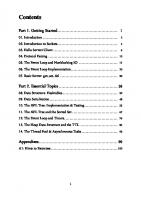
With this prep work out of the way, let's check whether our window creation works properly: 1. In source.cpp, add the following code: #defineGLFW_INCLUDE_VULKAN #include int main() { glfwInit(); glfwWindowHint(GLFW_CLIENT_API, GLFW_NO_API); glfwWindowHint(GLFW_RESIZABLE, GLFW_FALSE); GLFWwindow* window = glfwCreateWindow(1280, 720, "HELLO VULKAN ", nullptr, nullptr); while (!glfwWindowShouldClose(window)) {
glfwPollEvents(); } glfwDestroyWindow(window); glfwTerminate(); return 0; }
First, we include glfw3.h and ask GLFW to include some Vulkan-related headers. Then, in the main function, we initialize GLFW by calling glfwInit(). Then, we call the glfwWindowHint functions. The first glfwWindowHint function doesn't create the OpenGL context since it is created by Glfw by default. In the next function, we disable resizing for the window we are about to create. Then, we create the 1,280 x 720 window in a similar way to when we created the window in the OpenGL project. We create a while loop that checks whether the window should be closed. If the window doesn't need to be closed, we will poll the system events. Once this is done, we will destroy the window, terminate glfw, and return 0.
[ 269 ]
Getting Started with Vulkan
Chapter 9
2. This should give us a window to work with. Run the application in debug mode as an x64 executable to see the window being displayed and saying HELLO VULKAN, as shown in the following screenshot:
Vulkan validation layers and extensions Before we jump into creating the Vulkan application, we have to check for application validation layers and extensions. Let's go over these in more detail: Validation layers: Since so much control is given to developers, it is also possible for the developers to implement the Vulkan applications in an incorrect manner. The Vulkan validation layers check for such errors and tell the developer that they are doing something wrong and need to fix it. Extensions: Over the course of the development of the Vulkan API, new features may be introduced to newer GPUs. To keep Vulkan up to date, we need to extend its functionality by adding extensions. One example of this is the introduction of Ray Tracing in the RTX series of GPUs. In Vulkan, a new extension was created to support this change in the hardware by NVIDIA, that is, Vk_NV_ray_tracing. If our game uses this extension, we can check whether the hardware supports it. Similar extensions can be added and checked at the application level as well. One such extension is the Debug report extension, which we can generate if something goes wrong when we're implementing Vulkan. Our first class will add this functionality to the application to check for application validation layers and extensions. Let's start creating our first class. Create a new class called AppValidationLayersAndExtensions. In AppValidationLayersAndExtensions.h, add the following code: #pragmaonce #include #include #include
[ 270 ]
Getting Started with Vulkan
Chapter 9
#defineGLFW_INCLUDE_VULKAN #include classAppValidationLayersAndExtensions { public: AppValidationLayersAndExtensions(); ~AppValidationLayersAndExtensions(); const std::vector requiredValidationLayers = { "VK_LAYER_LUNARG_standard_validation" }; bool checkValidationLayerSupport(); std::vectorgetRequiredExtensions (boolisValidationLayersEnabled);
// Debug Callback VkDebugReportCallbackEXT callback; void setupDebugCallback(boolisValidationLayersEnabled, VkInstancevkInstance); void destroy(VkInstanceinstance, boolisValidationLayersEnabled);
// Callback * pCreateInfo, VkResultcreateDebugReportCallbackEXT( VkInstanceinstance, constVkDebugReportCallbackCreateInfoEXT constVkAllocationCallbacks* pAllocator, VkDebugReportCallbackEXT* pCallback) { auto func = (PFN_vkCreateDebugReportCallbackEXT) vkGetInstanceProcAddr(instance, "vkCreateDebugReportCallbackEXT"); if (func != nullptr) { return func(instance, pCreateInfo, pAllocator, pCallback); } else { returnVK_ERROR_EXTENSION_NOT_PRESENT; } } void DestroyDebugReportCallbackEXT( VkInstanceinstance,
[ 271 ]
Getting Started with Vulkan
Chapter 9
VkDebugReportCallbackEXTcallback, constVkAllocationCallbacks* pAllocator) { auto func = (PFN_vkDestroyDebugReportCallbackEXT) vkGetInstanceProcAddr(instance, "vkDestroyDebugReportCallbackEXT"); if (func != nullptr) { func(instance, callback, pAllocator); } } };
We include vulkan.h, iostream, vector, and glfw. Then, we create a vector called requiredValidationLayers; this is where we pass VK_LAYER_LUNARG _standard_validation. For our application, we will need the standard validation layer, which has all the validation layers in it. If we only need specific validation layers, then we can specify them individually as well. Next, we create two functions: one for checking the support for validation layers and one for getting the required extensions. To generate a report in case an error occurs, we need a debug callback. We will add two functions to it: one to set up the debug callback and one to destroy it. These functions will call the debug, create, and destroy functions; they will call vkGetInstanceProcAddr to get the pointers for the vkCreateDebugReportCallbackEXT and vkDestroyDebugReportCallbackEXT pointer functions so that we can call them. It would be better if it were less confusing to generate a debug report, but unfortunately, this is how it must be done. However, we only have to do this once. Let's move on to implementing AppValidationLayersAndExtentions.cpp: 1. First, we add the constructor and destructor, as follows: AppValidationLayersAndExtensions::AppValidationLayersAndExtensions(){}
AppValidationLayersAndExtensions::~AppValidationLayersAndExtensions(){} Then we add the implementation to checkValidationLayerSupport(). bool AppValidationLayersAndExtensions::checkValidationLayerSupport() { uint32_t layerCount; // Get count of validation layers available vkEnumerateInstanceLayerProperties(&layerCount, nullptr); // Get the available validation layers names
[ 272 ]
Getting Started with Vulkan
Chapter 9
std::vectoravailableLayers(layerCount); vkEnumerateInstanceLayerProperties(&layerCount, availableLayers.data()); for (const char* layerName : requiredValidationLayers) { //layers we require // boolean to check if the layer was found bool layerFound = false; for (const auto& layerproperties : availableLayers) { // If layer is found set the layar found boolean to true if (strcmp(layerName, layerproperties.layerName) == 0) { layerFound = true; break; } } if (!layerFound) { return false; } return true; } }
To check the supported validation layers, call the vkEnumerateInstanceLayerProperties function twice. We call it the first time to get the number of validation layers that are available. Once we have the count, we call it again to populate it with the names of the layers. We create an int called layerCount and pass it in the first time we call vkEnumerateInstanceLayerProperties. The function takes two parameters: the first is the count and the second is initially kept null. Once the function is called, we will know how many validation layers are available. For the names of the layers, we create a new vector called availableLayers of the VkLayerProperties type and initialize it with layerCount. Then, the function is called again, and this time we pass in layerCount and the vector as parameters to store the information. After, we make a check between the required layers and the available layers. If the validation layer was found, the function will return true. If not, it will return false.
[ 273 ]
Getting Started with Vulkan
Chapter 9
2. Next, we need to add the getRequiredInstanceExtentions function, as follows: std::vectorAppValidationLayersAndExtensions::getRequire dExtensions(boolisValidationLayersEnabled) { uint32_t glfwExtensionCount = 0; constchar** glfwExtensions; // Get extensions glfwExtensions = glfwGetRequiredInstanceExtensions (&glfwExtensionCount); std::vectorextensions(glfwExtensions, glfwExtensions + glfwExtensionCount); //debug report extention is added. if (isValidationLayersEnabled) { extensions.push_back("VK_EXT_debug_report"); } return extensions; }
The getRequiredInstanceExtensions phrase will get all the extensions that are supported by GLFW. It takes a Boolean to check whether the validation layers are enabled and returns a vector with the names of the supported extensions. In this function, we create a unint32_t called glfwExtensionCount and a const char for storing the names of the extensions. We call glfwGetRequiredExtentions, pass in glfwExtentionCount, and set it so that it's equal to glfwExtensions. This will store all the required extensions in glfwExtensions. We create a new extensions vector and store the glfwExtention names. If we have enabled the validation layer, then we can add an additional extension layer called VK_EXT_debug_report, which is the extension for generating a debug report. This extension vector is returned at the end of the function. 3. Then, we add the debug report callback function, which will generate a report message whenever there is an error, as follows: staticVKAPI_ATTRVkBool32VKAPI_CALL debugCallback( VkDebugReportFlagsEXTflags, VkDebugReportObjectTypeEXTobjExt, uint64_tobj,
[ 274 ]
Getting Started with Vulkan
Chapter 9
size_tlocation, int32_tcode, constchar* layerPrefix, constchar* msg, void* userData) { std::cerr checkValidationLayerSupport()) { throw std::runtime_error("Validation Layers Not Available !"); } // Create App And Vulkan Instance() vInstance = newVulkanInstance(); vInstance->createAppAndVkInstance(isValidationLayersEnabled, valLayersAndExt); // Debug CallBack valLayersAndExt->setupDebugCallback(isValidationLayersEnabled, vInstance->vkInstance);
}
First, we create a new AppValidationLayersAndExtensions instance. Then, we check whether the validation layers are enabled and check whether the validation layers are supported. If ValidationLayers is not available, a runtime error is sent out, saying that the validation layers are not available. If the validation layers are supported, a new instance of the VulkanInstance class is created and the createAppAndVkInstance function is called, which creates a new vkInstance. Once this is complete, we call the setupDebugCallBack function by passing in the Boolean and vkInstance. In the source.cpp file, include the VulkanContext.h file and call initVulkan after the window is created, as follows: #defineGLFW_INCLUDE_VULKAN #include #include"VulkanContext.h" int main() { glfwInit(); glfwWindowHint(GLFW_CLIENT_API, GLFW_NO_API); glfwWindowHint(GLFW_RESIZABLE, GLFW_FALSE); GLFWwindow* window = glfwCreateWindow(1280, 720, "HELLO VULKAN ", nullptr, nullptr); VulkanContext::getInstance()->initVulkan();
[ 281 ]
Getting Started with Vulkan
Chapter 9
while (!glfwWindowShouldClose(window)) { glfwPollEvents(); } glfwDestroyWindow(window); glfwTerminate(); return 0; }
Hopefully, you won't get any errors in the console window when you build and run the application. If you do get errors, go through each line of code and make sure there are no spelling mistakes:
Creating the window surface We need an interface for the window we created for the current platform so that we can present the images we will render. We use the VKSurfaceKHR property to get access to the window surface. To store the surface information that the OS supports, we will call the glfw function, glfwCreateWindowSurface, to create the surface that's supported by the OS. In VulkanContext.h, add a new variable of the VkSurfaceKHR type called surface, as follows: private: //surface VkSurfaceKHR surface;
Since we need access to the window instance we created in source.cpp, change the initVulkan function so that it accepts a GLFWwindow, as follows: void initVulkan(GLFWwindow* window);
[ 282 ]
Getting Started with Vulkan
Chapter 9
In VulkanContext.cpp, change the initVulkan implementation as follows and call the glfwCreateWindowSurface function, which takes in the Vulkan instance and the window. Next, pass in null for the allocator and the surface to create the surface object: void VulkanContext::initVulkan(GLFWwindow* window) { // -- Platform Specific // Validation and Extension Layers valLayersAndExt = new AppValidationLayersAndExtensions(); if (isValidationLayersEnabled && !valLayersAndExt-> checkValidationLayerSupport()) { throw std::runtime_error("Requested Validation Layers Not Available !"); } // Create App And Vulkan Instance() vInstance = new VulkanInstance(); vInstance->createAppAndVkInstance(isValidationLayersEnabled, valLayersAndExt); // Debug CallBack valLayersAndExt->setupDebugCallback(isValidationLayersEnabled, vInstance->vkInstance); // Create Surface if (glfwCreateWindowSurface(vInstance->vkInstance, window, nullptr, &surface) != VK_SUCCESS) { throw std::runtime_error(" failed to create window surface !"); } }
Finally, in source.cpp, change the initVulkan function, as follows: GLFWwindow* window = glfwCreateWindow(WIDTH, HEIGHT, "HELLO VULKAN ", nullptr, nullptr); VulkanContext::getInstance()->initVulkan(window);
[ 283 ]
Getting Started with Vulkan
Chapter 9
Picking a physical device and creating a logical device Now, we will create the Device class, which will be used to go through the different physical devices we have. We will choose one to render our application. To check whether your GPU is compatible with Vulkan, check the compatibility list on your GPU vendor's site or go to https://en.wikipedia.org/wiki/Vulkan_(API). Basically, any NVIDIA GPU from the Geforce 600 series and AMD GPU from the Radeon HD 2000 series and later should be supported. To access the physical device and create a logical device, we will create a new class that will allow us to access it whenever we want. Create a new class called Device. In Device.h, add the following includes: #include #include #include #include #include #include"VulkanInstance.h" #include"AppValidationLayersAndExtensions.h"
We will also add a couple of structs for the sake of convenience. The first is called SwapChainSupportDetails; it has access to VkSurfaceCapabilitiesKHR, which contains all the required details about the surface. We'll also add the surfaceFormats vector of the VkSurfaceFormatKHR type, which keeps track of all the different image formats the surface supports, and the presentModes vector of the VkPresentModeKHR type, which stores the presentation modes that the GPU supports. Rendered images will be sent to the window surface and displayed. This is how we are able to see the final rendered image using a renderer, such as OpenGL or Vulkan. Now, we can show these images to the window one at a time, which is fine if we want to look at a still image forever. However, when we run a game that is updated every 16 milliseconds (60 times in a second), there may be cases where the image has not been fully rendered, but it would be time to display it. At this point, we will see half-rendered images, which leads to screen tearing.
[ 284 ]
Getting Started with Vulkan
Chapter 9
To avoid this, we use double buffering. This allows us to render the image so that it has two different images, known as the front buffer and the back buffer, and ping-pong between them. Then, we present the buffer that has finished rendering and display it to the viewport while the next frame is still being rendered, as shown in the following diagram. There are different ways to present the image as well. We will look at these different presentation modes when we create the swapchain:
We need to create a struct to track the surface properties, format, and presentation modes, as follows: structSwapChainSupportDetails { VkSurfaceCapabilitiesKHR surfaceCapabilities; // size and images in swapchain std::vector surfaceFormats; std::vector presentModes; };
A GPU also has what is called QueueFamilies. Commands are sent to the GPU and then executed using queues. There are separate queues for different kinds of work. Render commands are sent to render queues, compute commands are sent to compute queues, and there are also presentation queues for presenting images. We also need to know which queues the GPU supports and how many of the queues are present.
[ 285 ]
Getting Started with Vulkan
Chapter 9
The renderer, compute, and presentation queues can be combined and are known as queue families. These queues can be combined in different ways to form a number of queue families. This means that there can be a combination of render and presentation queues that forms one queue family, while another family may just contain compute queues. Therefore, we have to check whether we have at least one queue family with graphics and presentation queues. This is because we need a graphics queue to pass our rendering commands into and a presentation queue to present the image after we render it. We will add one more struct to check for both, as follows: structQueueFamilyIndices { int graphicsFamily = -1; int presentFamily = -1; bool arePresent() { return graphicsFamily >= 0 && presentFamily >= 0; } };
Now, we will create the Device class itself. After creating the class, we add the constructor and destructor, as follows: { public: Device(); ~Device();
Then, we need to add some variables so that we can store the physical device, the SwapChainSupportDetails, and the QueueFamilyIndices, as follows: VkPhysicalDevice physicalDevice; SwapChainSupportDetails swapchainSupport; QueueFamilyIndices queueFamiliyIndices;
To create double buffering, we have to check that the device supports it. This is done using the VK_KHR_SWAPCHAIN_EXTENSION_NAME extension, which checks for a swapchain. First, we create a vector of the char* const and pass in the extension name, as follows: std::vectordeviceExtensions = { VK_KHR_SWAPCHAIN_EXTENSION_NAME };
[ 286 ]
Getting Started with Vulkan
Chapter 9
Then, we add the pickPhysicalDevice function, which will be selected depending on whether the device is suitable. While checking for suitability, we will check whether the selected device supports the swapchain extension, get the swapchain support details, and get the queue family indices, as follows: void pickPhysicalDevice (VulkanInstance* vInstance, VkSurfaceKHR surface); bool isDeviceSuitable(VkPhysicalDevice device, VkSurfaceKHR surface); bool checkDeviceExtensionSupported(VkPhysicalDevice device) ; SwapChainSupportDetails querySwapChainSupport(VkPhysicalDevice device, VkSurfaceKHR surface); QueueFamilyIndices findQueueFamilies(VkPhysicalDevice device, VkSurfaceKHR surface);
We will also add a getter function to get the queue families of the current device, as follows: QueueFamilyIndicesgetQueueFamiliesIndicesOfCurrentDevice();
Once we have the physical device we want to use, we will create an instance of the logical device. The logical device is an interface for the physical device itself. We will use the logical device to create buffers and so on. We will also store the current device graphics and present a queue so that we can send the graphics and presentation commands. Finally, we will add a destroy function, which is used to destroy the physical and logical devices we created, as follows: // ++++++++++++++ // Logical device // ++++++++++++++ void createLogicalDevice(VkSurfaceKHRsurface, boolisValidationLayersEnabled, AppValidationLayersAndExtensions *appValLayersAndExtentions); VkDevice logicalDevice; // handle to the graphics queue from the queue families of the gpu VkQueue graphicsQueue; // we can also have seperate queue for compute, memory transfer, etc. VkQueue presentQueue; // queue for displaying the framebuffer
void destroy(); }; // End of Device class
[ 287 ]
Getting Started with Vulkan
Chapter 9
That's all for the Device.h file. Let's move on to Device.cpp. First, we include Device.h and add the constructor and the destructor, as follows: #include"Device.h" Device::Device(){} Device::~Device(){ }
Now, the real work begins. We need to create the pickPhysicalDevice function, which takes a Vulkan instance and the VkSurface, as follows: voidDevice::pickPhysicalDevice(VulkanInstance* vInstance, VkSurfaceKHRsurface) { uint32_t deviceCount = 0; vkEnumeratePhysicalDevices(vInstance->vkInstance, &deviceCount, nullptr); if (deviceCount == 0) { throw std::runtime_error("failed to find GPUs with vulkan support !"); } std::cout getDevice()-> logicalDevice, swapChain, &imageCount, nullptr); swapChainImages.resize(imageCount); vkGetSwapchainImagesKHR(VulkanContext::getInstance()->getDevice()-> logicalDevice, swapChain, &imageCount, swapChainImages.data());
The creation of pictures is a bit more involved, but Vulkan automatically creates color pictures. We can set the picture format and extent as well: swapChainImageFormat = surfaceFormat.format; swapChainImageExtent= extent;
Then, we add the destroy function, which destroys the SwapChain by calling the vkDestroySwapchainKHR function: void SwapChain::destroy(){ // Swapchain vkDestroySwapchainKHR(VulkanContext::getInstance()-> getDevice()-> logicalDevice, swapChain, nullptr); }
In the VulkanApplication.h file, include the SwapChain header and create a new SwapChain instance in the VulkanApplication class. In VulkanApplication.cpp, in the initVulkan function, after creating the logical device, create the SwapChain as follows: swapChain = new SwapChain(); swapChain->create(surface);
[ 310 ]
Preparing the Clear Screen
Chapter 10
Build and run the application to make sure the SwapChain is created without any errors.
Creating Renderpass After creating the SwapChain, we move on to the Renderpass. Here, we specify how many color attachments and depth attachments are present and how many samples to use for each of them for each framebuffer. As mentioned at the start of this chapter, a framebuffer is a collection of target attachments. Attachments can be of type color, depth, and so on. The color attachment stores the color information that is presented to the viewport. There are other attachments that the end user doesn't see, but that are used internally. This includes depth, for example, which has all the depth information per pixel. In the render pass, apart from the type of attachments, we also specify how the attachments are used. For this book, we will be presenting what is rendered in a scene to the viewport, so we will just use a single pass. If we add a post-processing effect, we will take the rendered picture and apply this effect to it, for which we will need to use multiple passes. We will create a new class called Renderpass, in which we will create the render pass. In the Renderpass.h file, add the following includes and class: #include #include class Renderpass { public: Renderpass(); ~Renderpass(); VkRenderPass renderPass; void createRenderPass(VkFormat swapChainImageFormat); void destroy(); };
[ 311 ]
Preparing the Clear Screen
Chapter 10
In the class, add the constructor, destructor, and the VkRenderPass and renderPass variables. Add a new function called createRenderPass to create the Renderpass itself, which takes in the picture format. Also, add a function to destroy the Renderpass object after use. In the Renderpass.cpp file, add the following includes, as well as the constructor and destructor: #include"Renderpass.h" #include "VulkanContext.h" Renderpass::Renderpass(){}
Renderpass::~Renderpass(){}
We now add the createRenderPass function, in which we will add the functionality to create the Renderpass for the current scene to be rendered: voidRenderpass::createRenderPass(VkFormatswapChainImageFormat) { ... }
When we create the render pass, we have to specify the number and the type of attachments that we are using. So, for our project, we want only color attachments as we will only be drawing color information. We could also have a depth attachment, which stores depth information. We need to provide subpasses, and if so, then how many, as we could be using subpasses for adding post-processing effects to the current frame. For the attachments and subpasses, we have to populate structs to pass to them at the time of creating the render pass. So, let's populate the structs. First, we create the attachments: VkAttachmentDescription colorAttachment = {}; colorAttachment.format = swapChainImageFormat; colorAttachment.samples = VK_SAMPLE_COUNT_1_BIT; colorAttachment.loadOp = VK_ATTACHMENT_LOAD_OP_CLEAR; colorAttachment.storeOp = VK_ATTACHMENT_STORE_OP_STORE; colorAttachment.stencilLoadOp = VK_ATTACHMENT_LOAD_OP_DONT_CARE; colorAttachment.stencilStoreOp = VK_ATTACHMENT_STORE_OP_DONT_CARE; colorAttachment.initialLayout = VK_IMAGE_LAYOUT_UNDEFINED; colorAttachment.finalLayout = VK_IMAGE_LAYOUT_PRESENT_SRC_KHR;
[ 312 ]
Preparing the Clear Screen
Chapter 10
We create the struct and specify the format to be used, which is the same as the swapChainImage format. We have to provide the sample count as 1 as we are not going to be using multi-sampling. In loadOp and storeOp, we specify what to do with the data before and after rendering. We specify that at the time of loading the attachment, we will clear the data to a constant at the start. After the render process, we store the data so we can read from it later. We then decide what to do with the data before and after the stencil operation. Since we are not using the stencil buffer, we specify DON'T CARE during loading and storing. We also have to specify the data layout before and after processing the picture. The previous layout of the picture doesn't matter, but after rendering, the picture needs to be changed to the layout in order for it to be ready for presenting. Now we'll go through the subpass. Each subpass references the attachments that need to be specified as a separate structure: VkAttachmentReference colorAttachRef = {}; colorAttachRef.attachment = 0; colorAttachRef.layout = VK_IMAGE_LAYOUT_COLOR_ATTACHMENT_OPTIMAL;
In the subpass reference, we specify the attachment index, which is the 0th index and specify the layout, which is a color attachment with optimal performance. Next, we create the subpass structure: VkSubpassDescription subpass = {}; subpass.pipelineBindPoint = VK_PIPELINE_BIND_POINT_GRAPHICS; subpass.colorAttachmentCount = 1; subpass.pColorAttachments = &colorAttachRef;
In the pipeline bind point, we specify that this is a graphics subpass, as it could have been a compute subpass. Specify the attachment count as 1 and provide the color attachment. Now, we can create the renderpass info struct: std::array attachments = { colorAttachment }; VkRenderPassCreateInfo rpCreateInfo = {}; rpCreateInfo.sType = VK_STRUCTURE_TYPE_RENDER_PASS_CREATE_INFO; rpCreateInfo.attachmentCount = static_cast (attachments.size()); rpCreateInfo.pAttachments = attachments.data(); rpCreateInfo.subpassCount = 1; rpCreateInfo.pSubpasses = &subpass;
[ 313 ]
Preparing the Clear Screen
Chapter 10
We create an array of one element of the VkAttachmentDescription type, and then we create the info struct and pass in the type. The attachment count and the attachments are passed in, and then the subpass count and the subpass is passed in as well. Create the renderpass itself by calling vkCreateRenderPass and passing in the logical device, the create info, and the allocator callback to get the renderpass: if (vkCreateRenderPass(VulkanContext::getInstance()-> getDevice()->logicalDevice, &rpCreateInfo, nullptr, &renderPass) != VK_SUCCESS) { throw std::runtime_error(" failed to create renderpass !!"); }
Finally, in the destroy function, we call vkDestroyRenderPass to destroy it after we are done: voidRenderpass::destroy(){ vkDestroyRenderPass(VulkanContext::getInstance()-> getDevice()-> logicalDevice, renderPass, nullptr); }
In VulkanApplication.h, include RenderPass.h and create a render pass object. In VulkanApplication.cpp, after creating the swapchain, create the renderpass: renderPass = new Renderpass(); renderPass->createRenderPass(swapChain->swapChainImageFormat);
Now, build and run the project to make sure there are no errors.
Using render targets and framebuffers To use a picture, we have to create an ImageView. The picture doesn't have any information, such as mipmap levels, and you can't access a portion of the picture. However, by now using picture views, we specify the type of the texture and whether it has mipmaps. In addition, in renderpass, we specified the attachments per frame buffer. We will create framebuffers here and pass in the picture views as attachments. Create a new class called RenderTexture. In the RenderTexture.h file, add the following headers and then create the class itself: #include #include class RenderTexture
[ 314 ]
Preparing the Clear Screen
Chapter 10
{ public: RenderTexture(); ~RenderTexture(); std::vector _swapChainImages; VkExtent2D _swapChainImageExtent; std::vector swapChainImageViews; std::vector swapChainFramebuffers;
void createViewsAndFramebuffer(std::vector swapChainImages, VkFormat swapChainImageFormat, VkExtent2D swapChainImageExtent, VkRenderPass renderPass); void createImageViews(VkFormat swapChainImageFormat); void createFrameBuffer(VkExtent2D swapChainImageExtent, VkRenderPass renderPass); void destroy(); };
In the class, we add the constructor and destructor as usual. We will store swapChainImages and the extent to use it locally. We create two vectors to store the created ImageViews and framebuffers. To create the views and framebuffers, we will call the createViewsAndFramebuffers function, which takes the pictures, picture format, extent, and the renderpass as the input. This function intern will call createImageViews and CreateFramebuffer to create the views and buffers. We will add the destroy function, which destroys and releases the resources back to the system. In the RenderTexture.cpp file, we will add the following includes as well as the constructor and destructor: #include "RenderTexture.h" #include "VulkanContext.h" RenderTexture::RenderTexture(){} RenderTexture::~RenderTexture(){}
Then, add the createViewAndFramebuffer function: void RenderTexture::createViewsAndFramebuffer(std::vector swapChainImages, VkFormat swapChainImageFormat, VkExtent2D swapChainImageExtent, VkRenderPass renderPass){
[ 315 ]
Preparing the Clear Screen
Chapter 10
_swapChainImages = swapChainImages; _swapChainImageExtent = swapChainImageExtent; createImageViews(swapChainImageFormat); createFrameBuffer(swapChainImageExtent, renderPass); }
We first assign the images and imageExtent to the local variables. Then, we call the imageViews function, followed by createFramebuffer, in order to create both of them. To create the image views, use the createImageViews function: void RenderTexture::createImageViews(VkFormat swapChainImageFormat){ swapChainImageViews.resize(_swapChainImages.size()); for (size_t i = 0; i < _swapChainImages.size(); i++) { swapChainImageViews[i] = vkTools::createImageView (_swapChainImages[i], swapChainImageFormat, VK_IMAGE_ASPECT_COLOR_BIT); } }
We specify the vector size depending upon the swapchain image count first. For each of the image counts, we create image views using the createImageView function in the vkTool namespace. The createImageView function takes in the image itself, the image format, and ImageAspectFlag. This will be VK_IMAGE_ASPECT_COLOR_BIT or VK_IMAGE_ASPECT_DEPTH_BIT depending on the kind of view that you want to create for the image. The createImageView function is created in the Tools.h file under the vkTools namespace. The Tools.h file is as follows: #include #include #include namespace vkTools {
VkImageView createImageView(VkImage image, VkFormat format, VkImageAspectFlags aspectFlags);
}
[ 316 ]
Preparing the Clear Screen
Chapter 10
The implementation of the function is created in the Tools.cpp file as follows: #include "Tools.h" #include "VulkanContext.h" namespace vkTools { VkImageView createImageView(VkImage image, VkFormat format, VkImageAspectFlags aspectFlags) { VkImageViewCreateInfo viewInfo = {}; viewInfo.sType = VK_STRUCTURE_TYPE_IMAGE_VIEW_CREATE_INFO; viewInfo.image = image; viewInfo.viewType = VK_IMAGE_VIEW_TYPE_2D; viewInfo.format = format;
viewInfo.subresourceRange.aspectMask = aspectFlags; viewInfo.subresourceRange.baseMipLevel = 0; viewInfo.subresourceRange.levelCount = 1; viewInfo.subresourceRange.baseArrayLayer = 0; viewInfo.subresourceRange.layerCount = 1; VkImageView imageView; if (vkCreateImageView(VulkanContext::getInstance()-> getDevice()->logicalDevice, &viewInfo, nullptr, &imageView) != VK_SUCCESS) { throw std::runtime_error("failed to create texture image view !"); } return imageView; } }
To create the imageView, we have to populate the VkImageViewCreateInfo struct and then use the vkCreateImageView function to create the view itself. To populate the view info, we specify the structure type, the picture itself, the view type, which is VK_IMAGE_VIEW_TYPE_2D, and a 2D texture, and then specify the format. We pass in the aspectFlags for the aspect mask. We create the image view without any mipmap level or layers, so we set them to 0. We would only need multiple layers if we were making something like a VR game. We then create an imageView of the VkImage type and create it using the vkCreateImageView function, which takes in the logical device, the view info struct, and then the picture view is created and returned. That's all for the Tools file.
[ 317 ]
Preparing the Clear Screen
Chapter 10
We will use the Tools file and add more functions to it when we want functions that can be reused. Now, let's go back to the RenderTexture.cpp file and add in the function to create the framebuffer. We will create framebuffers for each frame in the swapchain. createFramebuffer requires the picture extent and the renderpass itself: void RenderTexture::createFrameBuffer(VkExtent2D swapChainImageExtent, VkRenderPass renderPass){ swapChainFramebuffers.resize(swapChainImageViews.size()); for (size_t i = 0; i < swapChainImageViews.size(); i++) {
std::array attachments = { swapChainImageViews[i] }; VkFramebufferCreateInfo fbInfo = {}; fbInfo.sType = VK_STRUCTURE_TYPE_FRAMEBUFFER_CREATE_INFO; fbInfo.renderPass = renderPass; fbInfo.attachmentCount = static_cast (attachments.size());; fbInfo.pAttachments = attachments.data();; fbInfo.width = swapChainImageExtent.width; fbInfo.height = swapChainImageExtent.height; fbInfo.layers = 1; if (vkCreateFramebuffer(VulkanContext::getInstance()-> getDevice()->logicalDevice, &fbInfo, NULL, &swapChainFramebuffers[i]) != VK_SUCCESS) { throw std::runtime_error(" failed to create framebuffers !!!"); } } }
For each frame that we create, the Framebuffer first populates the framebufferInfo struct and then calls vkCreateFramebuffer to create the Framebuffer itself. For each frame, we create a new info struct and specify the type of struct. We then pass the renderpass, the attachment count, and the attachment views, specify the width and height of the Framebuffer, and set the layers to 1.
[ 318 ]
Preparing the Clear Screen
Chapter 10
Finally, we create the framebuffer by calling the vkCreateFramebuffer function: void RenderTexture::destroy(){ // image views for (auto imageView : swapChainImageViews) { vkDestroyImageView(VulkanContext::getInstance()->getDevice()-> logicalDevice, imageView, nullptr); }
// Framebuffers for (auto framebuffer : swapChainFramebuffers) { vkDestroyFramebuffer(VulkanContext::getInstance()-> getDevice()->logicalDevice, framebuffer, nullptr); } }
In the destroy function, we destroy each of the picture views and framebuffers we created by calling vkDestroyImageView and vkDestroyFramebuffer. And that is all for the RenderTexture class. In VulkanApplication.h, include RenderTexture.h and create an instance of it called renderTexture in the VulkanApplication class. In the VulkanApplication.cpp file, include the initVulkan function and create a new RenderTexture: renderTexture = new RenderTexture(); renderTexture->createViewsAndFramebuffer(swapChain->swapChainImages, swapChain->swapChainImageFormat, swapChain->swapChainImageExtent, renderPass->renderPass);
Creating CommandBuffer In Vulkan, the drawing and other operations done on the GPU are performed using command buffers. The command buffers contain the draw commands, which are recorded and then executed. Draw commands are to be recorded and executed in every frame. To create a command buffer, we have to first create a command pool and then allocate command buffers from the command pool, and then the commands are recorded per frame.
[ 319 ]
Preparing the Clear Screen
Chapter 10
Let's create a new class for creating the command buffer pool and then allocate the command buffers. We also create a function to start and stop recording and to destroy the command buffers. Create a new class, called DrawCommandBuffer, and DrawCommandBuffer.h as follows: #include #include class DrawCommandBuffer { public: DrawCommandBuffer(); ~DrawCommandBuffer(); VkCommandPool commandPool; std::vector commandBuffers; void createCommandPoolAndBuffer(size_t imageCount); void beginCommandBuffer(VkCommandBuffer commandBuffer); void endCommandBuffer(VkCommandBuffer commandBuffer); void createCommandPool(); void allocateCommandBuffers(size_t imageCount); void destroy(); };
In the class, we create the constructor and destructor. We create variables to store the command pool and a vector to store VkCommandBuffer. We create one function initially to create the command pool and allocate the command buffers. The next two functions, beginCommandBuffer and endCommandBuffer, will be called when we want to start and stop recording the command buffer. The createCommandPool and allocateCommandBuffers functions will be called by createCommandPoolAndBuffer. We will create the destroy function to destroy the command buffers when we want the resources to be released to the system. In CommandBuffer.cpp, add the necessary includes and the constructor and destructor: #include "DrawCommandBuffer.h" #include "VulkanContext.h" DrawCommandBuffer::DrawCommandBuffer(){} DrawCommandBuffer::~DrawCommandBuffer(){}
[ 320 ]
Preparing the Clear Screen
Chapter 10
Then, we add createCommandPoolAndBuffer, which takes in the picture count: void DrawCommandBuffer::createCommandPoolAndBuffer(size_t imageCount){ createCommandPool(); allocateCommandBuffers(imageCount); }
The createCommandPoolAndBuffer function will call the createCommandPool and allocateCommandBuffers functions. First, we create the createCommandPool function. Commands have to be sent to a certain queue. We have to specify the queue when we create the command pool: void DrawCommandBuffer::createCommandPool() { QueueFamilyIndices qFamilyIndices = VulkanContext:: getInstance()->getDevice()-> getQueueFamiliesIndicesOfCurrentDevice(); VkCommandPoolCreateInfo cpInfo = {}; cpInfo.sType = VK_STRUCTURE_TYPE_COMMAND_POOL_CREATE_INFO; cpInfo.queueFamilyIndex = qFamilyIndices.graphicsFamily; cpInfo.flags = VK_COMMAND_POOL_CREATE_RESET_COMMAND_BUFFER_BIT; if (vkCreateCommandPool(VulkanContext::getInstance()-> getDevice()->logicalDevice, &cpInfo, nullptr, &commandPool) != VK_SUCCESS) { throw std::runtime_error(" failed to create command pool !!"); } }
To start, we get the queue family indices for the current device. To create the command pool, we have to populate the VkCommandPoolCreateInfo struct. As usual, we specify the type. Then, we set the queue family index in which the pool has to be created. After that, we set the VK_COMMAND_POOL_CREATE_RESET_COMMAND_BUFFER_BIT flags, which will reset the values of the command buffer every time. We then use the vkCreateCommandPool function by passing in the logical device and the info struct to get the command pool. Next, we create the allocateCommandBuffers function: void DrawCommandBuffer::allocateCommandBuffers(size_t imageCount) { commandBuffers.resize(imageCount); VkCommandBufferAllocateInfo cbInfo = {};
[ 321 ]
Preparing the Clear Screen
Chapter 10
cbInfo.sType = VK_STRUCTURE_TYPE_COMMAND_BUFFER_ALLOCATE_INFO; cbInfo.commandPool = commandPool; cbInfo.level = VK_COMMAND_BUFFER_LEVEL_PRIMARY; cbInfo.commandBufferCount = (uint32_t)commandBuffers.size(); if (vkAllocateCommandBuffers(VulkanContext::getInstance()-> getDevice()->logicalDevice, &cbInfo, commandBuffers.data()) != VK_SUCCESS) { throw std::runtime_error(" failed to allocate command buffers !!"); } }
We resize the commandBuffers vector. Then, to allocate the command buffers, we have to populate VkCommandBufferAllocateInfo. We first set the type of the struct and the command pool. Then, we have to specify the level of the command buffers. You can have a chain of command buffers, with the primary command buffer containing the secondary command buffer. For our use, we will set the command buffers as primary. We then set commandBufferCount, which is equal to the swapchain pictures. Then, we allocate the command buffers using the vkAllocateCommandBuffers function. We pass in the logical device, the info struct, and the command buffers to allocate memory for the command buffers. Then, we add beginCommandBuffer. This takes in the current command buffer to start recording commands in it: void DrawCommandBuffer::beginCommandBuffer(VkCommandBuffer commandBuffer){
VkCommandBufferBeginInfo cbBeginInfo = {}; cbBeginInfo.sType = VK_STRUCTURE_TYPE_COMMAND_BUFFER_BEGIN_INFO; cbBeginInfo.flags = VK_COMMAND_BUFFER_USAGE_SIMULTANEOUS_USE_BIT; if (vkBeginCommandBuffer(commandBuffer, &cbBeginInfo) != VK_SUCCESS) { throw std::runtime_error(" failed to begin command buffer !!"); } }
[ 322 ]
Preparing the Clear Screen
Chapter 10
To record command buffers, we also have to populate VkCommandBufferBeginInfoStruct. Once again, we specify the struct type and the VK_COMMAND_BUFFER_USAGE_SIMULTANEOUS_USE_BIT flag. This enables us to schedule the command buffer for the next frame while the last frame is still in use. vkBeginCommandBuffer is called to start recording the commands by passing in the current command buffer. Next, we add in the endCommandBuffer function. This function just calls vkEndCommandBuffer to stop recording to the command buffer: void DrawCommandBuffer::endCommandBuffer(VkCommandBuffer commandBuffer){ if (vkEndCommandBuffer(commandBuffer) != VK_SUCCESS) { throw std::runtime_error(" failed to record command buffer"); } }
We can then destroy the command buffers and the pool using the Destroy function. Here, we just destroy the pool, which will destroy the command buffers as well: void DrawCommandBuffer::destroy(){ vkDestroyCommandPool(VulkanContext::getInstance()-> getDevice()->logicalDevice, commandPool, nullptr); }
In the VulkanApplication.h file, include DrawCommandBuffer.h and create an object of this class. In VulkanApplication.cpp, in the VulkanInit function, after creating renderViewsAndFrameBuffers, create DrawCommandBuffer: renderTexture = new RenderTexture(); renderTexture->createViewsAndFramebuffer(swapChain->swapChainImages, swapChain->swapChainImageFormat, swapChain->swapChainImageExtent, renderPass->renderPass); drawComBuffer = new DrawCommandBuffer(); drawComBuffer->createCommandPoolAndBuffer(swapChain-> swapChainImages.size());
[ 323 ]
Preparing the Clear Screen
Chapter 10
Beginning and ending Renderpass Along with the commands being recorded in each frame, the renderpass is also processed for each frame where the color and the depth information is reset. So, since we only have color attachments in each frame, we have to clear the color information for each frame as well. Go back to the Renderpass.h file and add two new functions, called beginRenderPass and endRenderPass, in the class, as follows: class Renderpass { public: Renderpass(); ~Renderpass();
VkRenderPass renderPass; void createRenderPass(VkFormat swapChainImageFormat); void beginRenderPass(std::array clearValues, VkCommandBuffer commandBuffer, VkFramebuffer swapChainFrameBuffer, VkExtent2D swapChainImageExtent); void endRenderPass(VkCommandBuffer commandBuffer); void destroy(); };
In RenderPass.cpp, add the implementation of the beginRenderPass function: void Renderpass::beginRenderPass(std::array clearValues, VkCommandBuffer commandBuffer, VkFramebuffer swapChainFrameBuffer, VkExtent2D swapChainImageExtent) { VkRenderPassBeginInfo rpBeginInfo = {}; rpBeginInfo.sType = VK_STRUCTURE_TYPE_RENDER_PASS_BEGIN_INFO; rpBeginInfo.renderPass = renderPass; rpBeginInfo.framebuffer = swapChainFrameBuffer; rpBeginInfo.renderArea.offset = { 0,0 }; rpBeginInfo.renderArea.extent = swapChainImageExtent; rpBeginInfo.pClearValues = clearValues.data(); rpBeginInfo.clearValueCount = static_cast(clearValues.size()); vkCmdBeginRenderPass(commandBuffer,&rpBeginInfo, VK_SUBPASS_CONTENTS_INLINE); }
[ 324 ]
Preparing the Clear Screen
Chapter 10
We then populate the VkRenderPassBeginInfo struct. In this, we specify the struct type, pass in the renderpass and the current framebuffer, set the render area as the whole viewport, and pass in the clear value and the count. The clear value is the color value we want to clear the screen with, and the count would be 1, as we would like to clear only the color attachment. To begin the renderpass, we pass in the current command buffer, the info struct, and specify the third parameter as VK_SUBPASS_CONTENTS_INLINE, specifying that the renderpass commands are bound to the primary command buffer. In the endCommandBuffer function, we finish the Renderpass for the current frame: void Renderpass::endRenderPass(VkCommandBuffer commandBuffer){ vkCmdEndRenderPass(commandBuffer); }
To end the Renderpass, the vkCmdEndRenderPass function is called and the current command buffer is passed in. We have the required classes to get the clear screen going. Now, let's go to the Vulkan Application class and add some lines of code to get it working.
Creating the clear screen In the VulkanApplication.h file, we will add three new functions, called drawBegin, drawEnd, and cleanup. drawBegin will be called before we pass in any draw commands, and drawEnd will be called once the drawing is done and the frame is ready to be presented to the viewport. In the cleanup function, we will destroy all the resources. We will also create two variables. The first is uint32_t, to get the current picture from the swapchain, and the second is currentCommandBuffer of the VkCommandBuffer type to get the current command buffer: public: static VulkanApplication* getInstance(); static VulkanApplication* instance; ~VulkanApplication(); void initVulkan(GLFWwindow* window); void drawBegin(); void drawEnd();
[ 325 ]
Preparing the Clear Screen
Chapter 10
void cleanup(); private: uint32_t imageIndex = 0; VkCommandBuffer currentCommandBuffer; //surface VkSurfaceKHR surface;
In the VulkanApplication.cpp file, we add the implementation of the drawBegin and drawEnd functions: void VulkanApplication::drawBegin(){ vkAcquireNextImageKHR(VulkanContext::getInstance()-> getDevice()->logicalDevice, swapChain->swapChain, std::numeric_limits::max(), NULL, VK_NULL_HANDLE, &imageIndex); currentCommandBuffer = drawComBuffer->commandBuffers[imageIndex]; // Begin command buffer recording drawComBuffer->beginCommandBuffer(currentCommandBuffer); // Begin renderpass VkClearValue clearcolor = { 1.0f, 0.0f, 1.0f, 1.0f }; std::array clearValues = { clearcolor }; renderPass->beginRenderPass(clearValues, currentCommandBuffer, renderTexture->swapChainFramebuffers[imageIndex], renderTexture->_swapChainImageExtent);
}
First, we acquire the next picture from the swap chain. This is done using the Vulkan vkAcquireNextImageKHR API call. To do this, we pass in the logical device, the swapchain instance. Next, we need to pass in the timeout, for which we pass in the maximum numerical value as we don't care about the time limit. The next two variables are kept as null. These require a semaphore and a fence, which we will discuss in a later chapter. Finally, we pass in the imageIndex itself.
[ 326 ]
Preparing the Clear Screen
Chapter 10
Then, we get the current command buffer from the command buffers vector. We begin recording the command buffer by calling beginCommandBuffer and the commands will be stored in the currentCommandBuffer object. We now start the renderpass. In this, we pass the clear color value, which is the color purple, because why not? ! Pass in the current commandbuffer, the frame buffer, and the picture extent. We can now implement the drawEnd function: void VulkanApplication::drawEnd(){ // End render pass commands renderPass->endRenderPass(currentCommandBuffer); // End command buffer recording drawComBuffer->endCommandBuffer(currentCommandBuffer); // submit command buffer VkSubmitInfo submitInfo = {}; submitInfo.sType = VK_STRUCTURE_TYPE_SUBMIT_INFO; submitInfo.commandBufferCount = 1; submitInfo.pCommandBuffers = ¤tCommandBuffer; vkQueueSubmit(VulkanContext::getInstance()->getDevice()-> graphicsQueue, 1, &submitInfo, NULL);
// Present frame VkPresentInfoKHR presentInfo = {}; presentInfo.sType = VK_STRUCTURE_TYPE_PRESENT_INFO_KHR; presentInfo.swapchainCount = 1; presentInfo.pSwapchains = &swapChain->swapChain; presentInfo.pImageIndices = &imageIndex; vkQueuePresentKHR(VulkanContext::getInstance()-> getDevice()->presentQueue, &presentInfo); vkQueueWaitIdle(VulkanContext::getInstance()-> getDevice()->presentQueue); }
We end the renderpass and stop recording to the command buffer. Then, we have to submit the command buffer and present the frame. To submit the command buffer, we create a VkSubmitInfo struct and populate it with the struct type, the buffer count, which is 1 per frame, and the command buffer itself. The command is submitted to the graphics queue by calling vkQueueSubmit and passing in the graphics queue, the submission count, and the submit info.
[ 327 ]
Preparing the Clear Screen
Chapter 10
Once the frame is rendered, it is presented to the viewport using the present queue. To present the scene once it is drawn, we have to create and populate the VkPresentInfoKHR struct. For presentation, the picture is sent back to the swapchain. When we create the info and set the type of the struct, we also have to set the swapchain, the image index, and the swapchain count, which is 1. We then present the picture using vkQueuePresentKHR by passing in the present queue and the present info to the function. At the end, we wait for the host to finish the presentation operation of a given queue using the vkQueueWaitIdle function, which takes in the present queue. Also, it is better to clean up the resources when you are done with them, so add the cleanup function as well: void VulkanApplication::cleanup() { vkDeviceWaitIdle(VulkanContext::getInstance()-> getDevice()->logicalDevice); drawComBuffer->destroy(); renderTexture->destroy(); renderPass->destroy(); swapChain->destroy(); VulkanContext::getInstance()->getDevice()->destroy(); valLayersAndExt->destroy(vInstance->vkInstance, isValidationLayersEnabled); vkDestroySurfaceKHR(vInstance->vkInstance, surface, nullptr); vkDestroyInstance(vInstance->vkInstance, nullptr); } delete delete delete delete delete
drawComBuffer; renderTarget; renderPass; swapChain; device;
delete valLayersAndExt; delete vInstance; if (instance) { delete instance; instance = nullptr; }
[ 328 ]
Preparing the Clear Screen
Chapter 10
When we are destroying the objects, we have to call vkDeviceWaitIdle to stop using the device. Then, we destroy the objects in reverse order. So, we destroy the command buffer first, then the render texture resources, then renderpass, and then the swapchain. We then destroy the device, validation layer, surface, and finally, the Vulkan instance. Finally, we also delete the class instances we created for DrawCommandBuffer, RenderTarget, Renderpass, Swapchain, Device, ValidationLayersAndExtensions, and VulkanInstance. And finally, we also delete the instance of VulkanContext as well and set it to nullptr after deleting it. In the source.cpp file, in the while loop, call the drawBegin and drawEnd functions. Then call the cleanup function after the loop: #define GLFW_INCLUDE_VULKAN #include #include "VulkanApplication.h" int main() { glfwInit(); glfwWindowHint(GLFW_CLIENT_API, GLFW_NO_API); glfwWindowHint(GLFW_RESIZABLE, GLFW_FALSE); GLFWwindow* window = glfwCreateWindow(1280, 720, "HELLO VULKAN ", nullptr, nullptr); VulkanApplication::getInstance()->initVulkan(window); while (!glfwWindowShouldClose(window)) { VulkanApplication::getInstance()->drawBegin(); // draw command VulkanApplication::getInstance()->drawEnd(); glfwPollEvents(); } VulkanApplication::getInstance()->cleanup(); glfwDestroyWindow(window);
[ 329 ]
Preparing the Clear Screen
Chapter 10
glfwTerminate(); return 0; }
You will see a purple viewport, as follows, when you build and run the command:
The screen looks OK, but if you look at the console, you will see the following error, which says that when we call vkAcquireNextImageKHR, the semaphore and fence cannot both be NULL:
[ 330 ]
Preparing the Clear Screen
Chapter 10
Summary In this chapter, we looked at the creation of the swapchain, renderpass, render views, framebuffers, and the command buffers. We also looked at what each does and why they are important for rendering a clear screen. In the next chapter, we will create the resources that will enable us to render geometry to the viewport. Once we have the object resources ready, we will render the objects. We will then explore semaphores and fences and why they are needed.
[ 331 ]
11 Creating Object Resources In the previous chapter, we got our clear screen working and created the Vulkan instance. We also created the logical device, the swapchain, the render targets, and the views, as well as the draw command buffer, to record and submit commands to the GPU. Using it, we were able to have a purple clear screen. We haven't drawn any geometry yet, but we are now ready to do so. In this chapter, we will get most of the things that we need ready to render the geometries. We have to create vertex, index, and uniform buffers. The vertex, index, and uniform buffers will have information regarding the vertex attributes, such as position, color, normal and texture coordinates; index information will have the indices of the vertices we want to draw, and uniform buffers will have information such as a novel view projection matrix. We will need to create a descriptor set and layout, which will specify to which shader stage the uniform buffers are bound. We also have to generate the shaders that will be used to draw the geometry. To create both the object buffers and descriptor sets and layouts, we will create new classes so that they are compartmentalized and we can understand how they are related. Before we hop on the object buffer class, we will add the Mesh class that we created in the OpenGL project, and we will use the same class and add minor changes to it. The Mesh class has information regarding the vertex and index information for the different geometry shapes we want to draw. We will cover the following topics in this chapter: Updating the Mesh class for Vulkan Creating the ObjectBuffers class Creating the Descriptor class Creating the SPIR-V shader binary
Creating Object Resources
Chapter 11
Updating the Mesh class for Vulkan In the Mesh.h file, we just have to add a few lines of code to specify InputBindingDescription and InputAttributeDescription. In InputBindingDesciption, we specify the binding location, the stride of the data itself, and the input rate, which specifies whether the data is per vertex or per instance. In the Mesh.h file in the OpenGL project, we will just add functions to the Vertex struct: struct Vertex { glm::vec3 pos; glm::vec3 normal; glm::vec3 color; glm::vec2 texCoords; };
So, in the Vertex struct, add the function to retrieve AttributeDesciption: static VkVertexInputBindingDescription getBindingDescription() { VkVertexInputBindingDescription bindingDescription = {}; bindingDescription.binding = 0; bindingDescription.stride = sizeof(Vertex); bindingDescription.inputRate = VK_VERTEX_INPUT_RATE_VERTEX; return bindingDescription; }
In the function, VertexInputBindingDescriptor specifies that the binding is at the 0th index, the stride is equal to the size of the Vertex struct itself, and the input rate is VK_VERTEX_INPUT_RATE_VERTEX, which is per vertex. The function just returns the created binding description. Since we have four attributes in the vertex struct, we have to create an attribute descriptor for each one. Add the following function to the Vertex struct as well, which returns an array of four input attribute descriptors. For each attribute descriptor, we have to specify the binding location, which is 0 as specified in the binding description, the layout location for each attribute, the format of the data type, and the offset from the start of the Vertex struct: static std::array getAttributeDescriptions() {
[ 333 ]
Creating Object Resources
Chapter 11
std::array attributeDescriptions = {}; attributeDescriptions[0].binding = 0; // binding index, it is 0 as specified above attributeDescriptions[0].location = 0; // location layout // data format attributeDescriptions[0].format = VK_FORMAT_R32G32B32_SFLOAT; attributeDescriptions[0].offset = offsetof(Vertex, pos); // bytes since the start of the per vertex data attributeDescriptions[1].binding = 0; attributeDescriptions[1].location = 1; attributeDescriptions[1].format = VK_FORMAT_R32G32B32_SFLOAT; attributeDescriptions[1].offset = offsetof(Vertex, normal); attributeDescriptions[2].binding = 0; attributeDescriptions[2].location = 2; attributeDescriptions[2].format = VK_FORMAT_R32G32B32_SFLOAT; attributeDescriptions[2].offset = offsetof(Vertex, color); attributeDescriptions[3].binding = 0; attributeDescriptions[3].location = 3; attributeDescriptions[3].format = VK_FORMAT_R32G32_SFLOAT; attributeDescriptions[3].offset = offsetof(Vertex, texCoords); return attributeDescriptions; }
We will also create a new struct in the Mesh.h file to organize the uniform data information. So, create a new struct called UniformBufferObject: struct UniformBufferObject { glm::mat4 model; glm::mat4 view; glm::mat4 proj; };
At the top of the Mesh.h file, we will also include two define statements to tell GLM to use radians instead of degrees, and to use the normalized depth value: #define GLM_FORCE_RADIAN #define GLM_FORCE_DEPTH_ZERO_TO_ONE
That is all for Mesh.h. The Mesh.cpp file doesn't get modified at all.
[ 334 ]
Creating Object Resources
Chapter 11
Creating the ObjectBuffers class To create object-related buffers, such as vertex, index, and uniform, we will create a new class called ObjectBuffers. In the ObjectBuffers.h file, we will add the required include statements: #include #include #include "Mesh.h"
Then, we will create the class itself. In the public section, we will add the constructor and the destructor and add the required data types for creating vertex, index, and uniform buffers. We add a vector of the data vertex to set the vertex information of the geometry, create a VkBuffer instance called vertexBuffer to store the vertex buffer, and create a VkDeviceMemory instance called vertexBufferMemory: VkBuffer: This is the handle to the object buffer itself. VkDeviceMemory: Vulkan operates on memory data in the device's memory through the DeviceMemory object.
Similarly, we create a vector to store indices, and create an indexBuffer and an indexBufferMemory object, just as we did for vertex. For the uniform buffer, we only create uniformBuffer and uniformBuffer memory as a vector is not required. We add a createVertexIndexUniformBuffers function that takes in a Mesh type, and the vertices and indices will be set based on it. We also add a destroy function to destroy the Vulkan object we created. In the private section, we add three functions, which createVertexIndexUniformBuffers will call to create the buffers. That is all for the ObjectBuffers.h file. So, the ObjectBuffers class should be like this: class ObjectBuffers { public: ObjectBuffers(); ~ObjectBuffers(); std::vector vertices; VkBuffer vertexBuffer;
[ 335 ]
Creating Object Resources
Chapter 11
VkDeviceMemory vertexBufferMemory; std::vector indices; VkBuffer indexBuffer; VkDeviceMemory indexBufferMemory; VkBuffer uniformBuffers; VkDeviceMemory uniformBuffersMemory; void createVertexIndexUniformsBuffers(MeshType modelType); void destroy(); private: void createVertexBuffer(); void createIndexBuffer(); void createUniformBuffers(); };
Next, let's move on to the ObjectBuffers.cpp file. In this file, we include the headers and create the constructor and destructor: #include "ObjectBuffers.h" #include "Tools.h" #include "VulkanContext.h" ObjectBuffers::ObjectBuffers(){} ObjectBuffers::~ObjectBuffers(){}
Tools.h is included as we will be adding some more functionality to it that we will use. Next, we will create the createVertexIndexUniformBuffers function: void ObjectBuffers::createVertexIndexUniformsBuffers(MeshType modelType){ switch (modelType) { case case case case
kTriangle: Mesh::setTriData(vertices, indices); break; kQuad: Mesh::setQuadData(vertices, indices); break; kCube: Mesh::setCubeData(vertices, indices); break; kSphere: Mesh::setSphereData(vertices, indices); break;
} createVertexBuffer(); createIndexBuffer(); createUniformBuffers(); }
[ 336 ]
Creating Object Resources
Chapter 11
Similar to the OpenGL project, we will add a switch statement to set the vertex and index data depending on the mesh type. Then we call the createVertexBuffer, createIndexBuffer, and createUniformBuffers functions to set the respective buffers. We will create the createVertexBuffer function first. To create the vertex buffer, it is better if we create the buffer on the device that is on the GPU itself. Now, the GPU has two types of memories: HOST VISIBLE and DEVICE LOCAL. HOST VISIBLE is a part of the GPU memory that the CPU has access to. This memory is not very large, so it is used for storing up to 250 MB of data. For larger chunks of data, such as vertex and index data, it is better to use the DEVICE LOCAL memory, which the CPU doesn't have access to. So, how do you transfer data to the DEVICE LOCAL memory? Well, we first have to copy the data to the HOST VISIBLE section on the GPU, and then copy it to the DEVICE LOCAL memory. So, we first create what is called a staging buffer, copy the vertex data into it, and then copy the staging buffer to the actual vertex buffer:
(Source: https://www.youtube.com/watch?v=rXSdDE7NWmA)
Let's add functionality into the VkTool file to create the different kinds of buffers. With this, we can create both the staging buffer and vertex buffer itself. So, in the VkTools.h file in the vkTools namespace, add a new function called createBuffer. This function takes in five parameters: The first is VkDeviceSize, which is the size of the data for which the buffer is to be created. The second is the usage flag, which tells us what the buffer is going to be used for.
[ 337 ]
Creating Object Resources
Chapter 11
The third is the memory properties where we want to create the buffer; this is where we will specify whether we want it in the HOST VISIBLE section or the DEVICE LOCAL area. The fourth is the buffer itself. The fifth is the buffer memory to bind the buffer to the following: namespace vkTools { VkImageView createImageView(VkImage image, VkFormat format, VkImageAspectFlags aspectFlags); void createBuffer(VkDeviceSize size, VkBufferUsageFlags usage, VkMemoryPropertyFlags properties, VkBuffer &buffer, VkDeviceMemory& bufferMemory); }
In the VKTools.cpp file, we add the functionality for creating the buffer and binding it to bufferMemory. In the namespace, add the new function: void createBuffer(VkDeviceSize size, VkBufferUsageFlags usage, VkMemoryPropertyFlags properties, VkBuffer &buffer, // output VkDeviceMemory& bufferMemory) { // code }
Before binding the buffer, we create the buffer itself. Hence, we populate the VkBufferCreateInfo struct as follows: VkBufferCreateInfo bufferInfo = {}; bufferInfo.sType = VK_STRUCTURE_TYPE_BUFFER_CREATE_INFO; bufferInfo.size = size; bufferInfo.usage = usage; bufferInfo.sharingMode = VK_SHARING_MODE_EXCLUSIVE; if (vkCreateBuffer(VulkanContext::getInstance()-> getDevice()->logicalDevice, &bufferInfo, nullptr, &buffer) != VK_SUCCESS) { throw std::runtime_error(" failed to create vertex buffer "); }
[ 338 ]
Creating Object Resources
Chapter 11
The struct takes the usual type first, and then we set the buffer size and usage. We also need to specify the buffer sharing mode, because a buffer can be shared between queues, such as graphics and compute, or could be exclusive to one queue. So, here we specify that the buffer is exclusive to the current queue. Then, the buffer is created by calling vkCreateBuffer and passing in logicalDevice and bufferInfo. Next, to bind the buffer, we have to get the suitable memory type for our specific use of the buffer. So, first we have to get the memory requirements for the kind of buffer we are creating. The requisite memory requirement is received by calling the vkGetBUfferMemoryRequirements function, which takes in the logical device, the buffer, and the memory requirements get stored in a variable type called VkMemoryRequirements. We get the memory requirements as follows: VkMemoryRequirements memrequirements; vkGetBufferMemoryRequirements(VulkanContext::getInstance()->getDevice()-> logicalDevice, buffer, &memrequirements);
To bind memory, we have to populate the VkMemoryAllocateInfo struct. It requires the allocation size and the memory index of the type of memory. Each GPU has a different memory type index, with a different heap index and memory type. These are the corresponding values for 1080Ti:
[ 339 ]
Creating Object Resources
Chapter 11
We will now add a new function in VkTools to get the correct kind of memory index for our buffer usage. So, add a new function in VkTool.h under the vkTools namespace, called findMemoryTypeIndex: uint32_t findMemoryTypeIndex(uint32_t typeFilter, VkMemoryPropertyFlags properties);
It takes two parameters, which are the memory type bits available and the memory properties that we need. Add the implementation for the findMemoryTypeIndex function to the VkTools.cpp file. Under the namespace, add the following function: uint32_t findMemoryTypeIndex(uint32_t typeFilter, VkMemoryPropertyFlags properties) { //-- Properties has two arrays -- memory types and memory heaps VkPhysicalDeviceMemoryProperties memProperties; vkGetPhysicalDeviceMemoryProperties(VulkanContext:: getInstance()->getDevice()->physicalDevice, &memProperties); for (uint32_t i = 0; i < memProperties.memoryTypeCount; i++) { if ((typeFilter & (1 getDevice()->logicalDevice, &layoutCreateInfo, nullptr, &descriptorSetLayout) != VK_SUCCESS) { throw std::runtime_error("failed to create descriptor set layout"); } }
For our project, the layout set will just have one layout binding, which is the one struct with the model, view, and projection matrix information.
[ 350 ]
Creating Object Resources
Chapter 11
We have to populate the VkDescriptorSetLayout struct and specify the binding location index, the count, the type of information we will be passing in, and the shader stage to which the uniform buffer will be sent. After creating the set layout, we populate VkDescriptorSetLayoutCreateInfo, in which we specify the binding count and the bindings itself. Then, we call the vkCreateDescriptorSetLayout function to create the descriptor set layout by passing in the logical device and the layout creation info. Next, we add the createDescriptorPoolAndAllocateSets function: void Descriptor::createDescriptorPoolAndAllocateSets(uint32_t _swapChainImageCount) { // create pool std::array poolSizes = {}; poolSizes[0].type = VK_DESCRIPTOR_TYPE_UNIFORM_BUFFER; poolSizes[0].descriptorCount = _swapChainImageCount;
VkDescriptorPoolCreateInfo poolInfo = {}; poolInfo.sType = VK_STRUCTURE_TYPE_DESCRIPTOR_POOL_CREATE_INFO; poolInfo.poolSizeCount = static_cast(poolSizes.size()); poolInfo.pPoolSizes = poolSizes.data(); poolInfo.maxSets = _swapChainImageCount; if (vkCreateDescriptorPool(VulkanContext::getInstance()-> getDevice()->logicalDevice, &poolInfo, nullptr, &descriptorPool) != VK_SUCCESS) { throw std::runtime_error("failed to create descriptor pool "); }
// allocate std::vector layouts(_swapChainImageCount, descriptorSetLayout); VkDescriptorSetAllocateInfo allocInfo = {}; allocInfo.sType = VK_STRUCTURE_TYPE_DESCRIPTOR_SET_ALLOCATE_INFO; allocInfo.descriptorPool = descriptorPool; allocInfo.descriptorSetCount = _swapChainImageCount; allocInfo.pSetLayouts = layouts.data(); if (vkAllocateDescriptorSets(VulkanContext::getInstance()-> getDevice()->logicalDevice, &allocInfo, &descriptorSet)
[ 351 ]
Creating Object Resources
Chapter 11
!= VK_SUCCESS) { throw std::runtime_error("failed to allocate descriptor sets ! "); } }
To create the descriptor pool, we have to specify the pool size using VkDescriptorPoolSize. We create an array of it and call it poolSizes. Since, in the layout set, we just have the uniform buffer, we set its type and set the count equal to the swap-chain-image count. To create the descriptor pool, we have to specify the type, poolsize count, and the pool-size data. We also have to set the maxsets, which is the maximum number of sets that can be allocated from the pool, which is equal to the swap-chain-image count. We create the descriptor pool by calling vkCreateDescriptorPool and passing in the logical device and the pool-creation info. Next, we have to specify allocation parameters for the description sets. We create a vector of the descriptor set layout. Then, we create the VkDescriptionAllocationInfo struct to populate it. We pass in the description pool, the descriptor set count (which is equal to the swap-chain-images count), and pass in the layout data. Then, we allocate the descriptor sets by calling vkAllocateDescriptorSets and passing in the logical device and the create info struct. Finally, we will add the populateDescriptorSets function, as follows: void Descriptor::populateDescriptorSets(uint32_t _swapChainImageCount, VkBuffer uniformBuffers) { for (size_t i = 0; i < _swapChainImageCount; i++) { // Uniform buffer info VkDescriptorBufferInfo uboBufferDescInfo = {}; uboBufferDescInfo.buffer = uniformBuffers; uboBufferDescInfo.offset = 0; uboBufferDescInfo.range = sizeof(UniformBufferObject); VkWriteDescriptorSet uboDescWrites; uboDescWrites.sType = VK_STRUCTURE_TYPE_WRITE_DESCRIPTOR_SET; uboDescWrites.pNext = NULL; uboDescWrites.dstSet = descriptorSet; uboDescWrites.dstBinding = 0; // binding index of 0 uboDescWrites.dstArrayElement = 0; uboDescWrites.descriptorType = VK_DESCRIPTOR_TYPE_UNIFORM_BUFFER; uboDescWrites.descriptorCount = 1; uboDescWrites.pBufferInfo = &uboBufferDescInfo; // uniforms
[ 352 ]
Creating Object Resources
Chapter 11 buffers
uboDescWrites.pImageInfo = nullptr; uboDescWrites.pTexelBufferView = nullptr;
std::array descWrites = { uboDescWrites};
vkUpdateDescriptorSets(VulkanContext::getInstance()-> getDevice()->logicalDevice, static_cast (descWrites.size()), descWrites.data(), 0, nullptr); } }
This function takes in the swapchain image count and the uniform buffer as parameters. For both the images of the swapchain, the configuration of the descriptor needs to be updated by calling vkUpdateDescriptorSets. This function takes in an array of VkWriteDescriptorSet. Now, VkWriteDescriptorSet takes in either a buffer, image struct, or texelBufferView as a parameter. Since we are going to use the uniform buffer, we will have to create it and pass it in. VkdescriptorBufferInfo takes in a buffer (which will be the uniform buffer we created), takes an offset (which is none in this case), and then takes the range (which is the size of the buffer itself). After creating it, we can start specifying VkWriteDescriptorSet. This takes in the type, th descriptorSet, and the binding location (which is the 0 index). It has no array elements in it, and it takes the descriptor type (which is the uniform buffer type); the descriptor count is 1, and we pass in the buffer info struct. For the image info and the texel buffer view, we specify none, as it is not being used. We then create an array of VkWriteDescriptorSet and add the uniform buffer descriptor writes info we created, called uboDescWrites, to it. We update the descriptor set by calling vkUpdateDescriptorSets and pass in the logical device, the descriptor writes size, and the data. That's it for the populateDescriptorSets function. We finally add the destroy function, which destroys the descriptor pool and the descriptor set layout. Add the function as follows: void Descriptor::destroy(){ vkDestroyDescriptorPool(VulkanContext::getInstance()-> getDevice()->logicalDevice, descriptorPool, nullptr); vkDestroyDescriptorSetLayout(VulkanContext::getInstance()-> getDevice()->logicalDevice, descriptorSetLayout, nullptr); }
[ 353 ]
Creating Object Resources
Chapter 11
Creating the SPIR-V shader binary Unlike OpenGL, which takes in GLSL (OpenGL Shading Language) human-readable files for shaders, Vulkan takes in shaders in binary or byte code format. All shaders, whether vertex, fragment, or compute, have to be in byte code format. SPIR-V is also good for cross-compilation, making porting shader files a lot easier. If you have a Direct3D HLSL shader code, it can be compiled to SPIR-V format and can be used in a Vulkan application, making it very easy to port Direct3D games to Vulkan. The shader is initially written in GLSL, with some minor changes to how we wrote it for OpenGL. A compiler is provided, which compiles the code from GLSL to SPIR-V format. The compiler is included with the Vulkan SDK installation. The basic vertex-shader GLSL code is as follows: #version 450 #extension GL_ARB_separate_shader_objects : enable layout (binding = 0) uniform UniformBufferOBject{ mat4 model; mat4 view; mat4 proj; } ubo; layout(location layout(location layout(location layout(location
= = = =
0) 1) 2) 3)
in in in in
vec3 vec3 vec3 vec2
inPosition; inNormal; inColor; inTexCoord;
layout(location = 0) out vec3 fragColor;
void main() { gl_Position = ubo.proj * ubo.view * ubo.model * vec4(inPosition, 1.0); fragColor = inColor; }
The shader should look very familiar, with some minor changes. For example, the GLSL version is still specified at the top. In this case, it is #version 450. But we also see new things, such as #extension GL_ARB_seperate_shader_objects: enable. This specifies the extension that the shader uses. In this case, an old extension is needed, which basically lets us use vertex and fragment shaders as separate files. Extensions need to be approved by the Architecture Review Board (ARB).
[ 354 ]
Creating Object Resources
Chapter 11
Apart from the inclusion of the extension, you may have noticed that there is a location layout specified for all data types. And you may have noticed that when creating vertex and uniform buffers, we had to specify the binding index for the buffers. In Vulkan, there is no equivalent to GLgetUniformLocation to get the location index of a uniform buffer. This is because it takes quite a bit of system resources to get the location. Instead, we specify and sort of hardcode the value of the index. The uniform buffers, as well as the in and out buffer can all be assigned an index of 0 as they are of different data types. Since the uniform buffer will be sent as a st ruct with model, view, and projection matrices, a similar struct is created in the shader and assigned to the 0th index of the uniform layout. All four attributes are also assigned a layout index 0, 1, 2, and 3, as specified in the Mesh.h file under the Vertex struct when setting the VkVertexInputAttributeDescription for the four attributes. The out is also assigned a layout location index of 0, and the data type is specified as vec3. Then, in the main function of the shader, we set the gl_Position value by multiplying the local coordinate of the object by the model, view, and projection matrix received from the uniform buffer struct. Furthermore, outColor is set as inColor received. The fragment shader is as follows: open a .txt file, add the shader code to it, and name the file basic. Also, change the extension to *.vert from *.txt: #version 450 #extension GL_ARB_separate_shader_objects : enable layout(location = 0) in vec3 fragColor; layout(location = 0) out vec4 outColor; void main() { outColor = vec4(fragColor, 1.0f); }
Here, we specify the GLSL version and the extension to use. There are in and out, both of which have a location layout of 0. Note that in is a vec3 called fragColor, which is what we sent out of the vertex shader, and that outColor is a vec4. In the main function of the shader file, we convert vec3 to vec4 and set the resultant color to outColor. Add the fragment shader to a file called basic.frag. In the VulkanProject root directory, create a new folder called shaders and add the two shader files to it:
[ 355 ]
Creating Object Resources
Chapter 11
Create a new folder called SPIRV, as this is where we will put the compiled SPIRV bytecode file. To compile the .glsl files, we will use the glslValidator.exe file, which was installed when we installed the Vulkan SDK. Now, to compile the code, we can use the following command: glslangValidator.exe -V basic.frag -o basic.frag.spv
Hold Shift on the keyboard, right-click in the shaders folder, and click the Open PowerShell window here:
In PowerShell, type in the following command:
Make sure the V is capitalized and the o is lowercase, otherwise, it will give compile errors. This will create a new spirv file in the folder. Change frag to vert to compile the SPIRV vertex shader:
[ 356 ]
Creating Object Resources
Chapter 11
This will create the vertex and fragment shader SPIRV binaries in the folder:
Instead of compiling the code manually each time, we can create a .bat file that can do this for us, and put the compiled SPIRV binaries in the SPIRV folder. In the shaders folder, create a new .txt file and name it glsl_spirv_compiler.bat. In the .bat file, add the following: @echo off echo compiling glsl shaders to spirv for /r %%i in (*.vert;*.frag) do %VULKAN_SDK%\Bin32\glslangValidator.exe -V "%%i" -o "%%~dpiSPIRV\%%~nxi".spv
Save and close the file. Now double-click on the .bat file to execute it. This will compile the shaders and place the compiled binary in the SPIRV shader files:
You can delete the SPIRV files in the shaders folder that we compiled earlier using the console command because we will be using the shader files in the SPIRV subfolder.
[ 357 ]
Creating Object Resources
Chapter 11
Summary In this chapter, we created all the resources required to render the geometry. First of all, we added the Mesh class, which has vertex and index information for all the mesh types, including triangle, quad, cube, and sphere. Then, we created the ObjectBuffers class, which was used to store and bind the buffers to the GPU memory using the VkTool file. We also created a separate descriptor class, which has our descriptor set layout and pool. In addition, we created descriptor sets. Finally, we created the SPIRV bytecode shader files, which were compiled from the GLSL shader. In the next chapter, we will use the resources we created here to draw our first colored geometry.
[ 358 ]
12 Drawing Vulkan Objects In the previous chapter, we created all the resources that were required for an object to be drawn. In this chapter, we will create the ObjectRenderer class, which will draw an object on the viewport. This class is used so that we have an actual geometric object to draw and view alongside our awesome purple viewport. We will also learn how to synchronize CPU and GPU operations at the end of the chapter, which will remove the validation error that we got in Chapter 11, Creating Object Resources. Before we set the scene up for rendering, we have to prepare one last thing for the geometry render; that is, the graphics pipeline. We will begin setting this up next. In this chapter, we will cover the following topics: Preparing the GraphicsPipeline class The ObjectRenderer class Changes to the VulkanContext class The Camera class Drawing an object Synchronizing an object
Drawing Vulkan Objects
Chapter 12
Preparing the GraphicsPipeline class The graphics pipeline defines the pipeline an object should follow when it is drawn. As we discovered in Chapter 2, Mathematics and Graphics Concepts, there is a series of steps that we need to follow to draw an object:
In OpenGL, pipeline states can be changed at any time, just like we enabled and disabled blending when drawing text in Chapter 8, Enhancing Your Game with Collision, Loop, and Lighting. However, changing states takes up a lot of system resources, which is why Vulkan discourages you from changing states at will. Therefore, you will have to set the pipeline states in advance for each object. Before you create a pipeline's state, you also need to create a pipeline layout that takes the descriptor set layout we created in the previous chapter. So, we will create the pipeline layout first.
[ 360 ]
Drawing Vulkan Objects
Chapter 12
Then, we also need to provide the shader SPIR-V files, which will have to be read to understand how to create the shader modules. So, add the functionality to the class. We then populate the graphics pipeline info, which will use the different shader modules that we created. We also specify the vertex input state, which will have information regarding the buffer's bindings and attributes, which we created earlier when defining the vertex struct. The input assembly state also needs to be specified, which describes the kind of geometry to be drawn with the vertices. Note that we can draw points, lines, or triangles with the given set of vertices. Additionally, we need to specify the viewport state, which describes the region of the framebuffer that will be rendered, as we can display part of the framebuffer to the viewport if necessary. In our case, we will be displaying the whole region to the viewport. We specify the rasterization state, which will perform depth testing and back-face culling, and convert the geometry to rasterized lines – which will be colored, as specified in the fragment shader. The multisampling state will specify whether you want to enable multisampling to enable anti-aliasing. The depth and stencil states specify whether the depth and stencil tests are enabled and are to be performed on the object. The color blending state specifies whether blending is enabled or not. Finally, the dynamic state enables us to change some pipeline states dynamically without creating the pipeline again. We won't be using dynamic states for our implementation. With all this set, we can create the graphics pipeline for the object. Let's begin by creating a new class for the graphics pipeline. In the GraphicsPipeline.h file, add the following: #include #include #include class GraphicsPipeline { public: GraphicsPipeline(); ~GraphicsPipeline(); VkPipelineLayout pipelineLayout; VkPipeline graphicsPipeline; void createGraphicsPipelineLayoutAndPipeline(VkExtent2D swapChainImageExtent, VkDescriptorSetLayout descriptorSetLayout, VkRenderPass renderPass);
[ 361 ]
Drawing Vulkan Objects
Chapter 12
void destroy(); private: std::vector readfile(const std::string& filename); VkShaderModule createShaderModule(const std::vector & code); void createGraphicsPipelineLayout(VkDescriptorSetLayout descriptorSetLayout); void createGraphicsPipeline(VkExtent2D swapChainImageExtent, VkRenderPass renderPass); };
We include the usual headers and also fstream, because we will need it for reading the shader files. We then create the class itself. In the public section, we will add the constructor and destructor. We create objects for storing the pipelineLayout and graphicsPipeline of the VkPipelineLayout and VkPipeline types respectively. We create a new function called createGraphicsPipelineLayoutAndPipeline, which takes VkExtent2D, VkDesriptorSetLayout, and VkRenderPass, as this is required for creating both the layout and the actual pipeline itself. The function will internally be calling createGraphicsPipelineLayout and createGraphicsPipeline, which will create the layout and the pipeline respectively. These functions are added to the private section. In the public section, we also have a function called destroy, which will destroy all the created resources. In the private section, we also have two more functions. The first is the readFile function, which reads the SPIR-V file, and the second is createShaderModule, which will create the shader module from the read shader file. Let's now move on to the GraphicsPipeline.cpp file: #include "GraphicsPipeline.h" #include "VulkanContext.h" #include "Mesh.h" GraphicsPipeline::GraphicsPipeline(){} GraphicsPipeline::~GraphicsPipeline(){}
In the preceding code block, we include the GraphicsPipeline.h, VulkanContext.h, and Mesh.h files because they are required. We also add the implementation for the constructor and the destructor.
[ 362 ]
Drawing Vulkan Objects
Chapter 12
We then add the createGraphicsPipelineLayoutAndPipeline function, as follows: void GraphicsPipeline::createGraphicsPipelineLayoutAndPipeline(VkExtent2D swapChainImageExtent, VkDescriptorSetLayout descriptorSetLayout, VkRenderPass renderPass){ createGraphicsPipelineLayout(descriptorSetLayout); createGraphicsPipeline(swapChainImageExtent, renderPass); }
The createPipelineLayout function is created as follows. We have to create a createInfo struct with the structure type, set the descriptorLayout and count, and then create the pipeline layout using the vkCreatePipelineLayout function: void GraphicsPipeline::createGraphicsPipelineLayout(VkDescriptorSetLayout descriptorSetLayout){
VkPipelineLayoutCreateInfo pipelineLayoutInfo = {}; pipelineLayoutInfo.sType = VK_STRUCTURE_TYPEPIPELINE_ LAYOUT_CREATE_INFO; // used for passing uniform objects and images to the shader pipelineLayoutInfo.setLayoutCount = 1; pipelineLayoutInfo.pSetLayouts = &descriptorSetLayout;
if (vkCreatePipelineLayout(VulkanContext::getInstance()-> getDevice()->logicalDevice, &pipelineLayoutInfo, nullptr, &pipelineLayout) != VK_SUCCESS) { throw std::runtime_error(" failed to create pieline layout !"); } }
Before we add the create pipeline function, we will add the readFile and createShaderModule functions: std::vector GraphicsPipeline::readfile(const std::string& filename) { std::ifstream file(filename, std::ios::ate | std::ios::binary); if (!file.is_open()) {
[ 363 ]
Drawing Vulkan Objects
Chapter 12
throw std::runtime_error(" failed to open shader file"); } size_t filesize = (size_t)file.tellg(); std::vector buffer(filesize); file.seekg(0); file.read(buffer.data(), filesize); file.close(); return buffer; }
readFile takes a SPIR-V code file, opens and reads it, saves the contents of the file into a vector of char called buffer, and then returns it. We then add the createShaderModule
function, as follows:
VkShaderModule GraphicsPipeline::createShaderModule(const std::vector & code) { VkShaderModuleCreateInfo cInfo = {}; cInfo.sType = VK_STRUCTURE_TYPE_SHADER_MODULE_CREATE_INFO; cInfo.codeSize = code.size(); cInfo.pCode = reinterpret_cast(code.data()); VkShaderModule shaderModule; if (vkCreateShaderModule(VulkanContext::getInstance()->getDevice()-> logicalDevice, &cInfo, nullptr, &shaderModule) != VK_SUCCESS) { throw std::runtime_error(" failed to create shader module !"); } return shaderModule; }
To create the shader module, which is required for ShaderStageCreateInfo to create the pipeline, we need to populate the ShaderModuleCreateInfo, which takes the code and the size from the buffer to create the shader module. The shader module is created using the vkCreateShaderModule function, which takes the device and the CreateInfo. Once the shader module is created, it is returned. To create the pipeline, we have to create the following info structs: the shader stage info, the vertex input info, the input assembly struct, the viewport info struct, the rasterization info struct, the multisample state struct, the depth stencil struct (if required), the color blending struct, and the dynamic state struct.
[ 364 ]
Drawing Vulkan Objects
Chapter 12
So, let's create each, one after the other, starting with the shader stage struct. Add the createGraphicsPipeline function, and in it, we will create the pipeline: void GraphicsPipeline::createGraphicsPipeline(VkExtent2D swapChainImageExtent, VkRenderPass renderPass) { ... }
In this function, we will now add the following, which will create the graphics pipeline.
ShaderStageCreateInfo To create the vertex shader, ShaderStageCreateInfo, we need to read the shader code first and create the shader module for it: auto vertexShaderCode = readfile("shaders/SPIRV/basic.vert.spv"); VkShaderModule vertexShadeModule = createShaderModule(vertexShaderCode);
To read the shader file, we pass in the location of the shader file. Then, we pass the read code into the createShaderModule function, which will give us vertexShaderModule. We create the shader stage info struct for the vertex shader and pass in the stage, the shader module, and the name of the function to be used in the shader, which is main, in our case: VkPipelineShaderStageCreateInfo vertShaderStageCreateInfo = {}; vertShaderStageCreateInfo.sType = VK_STRUCTURE_TYPE_PIPELINE_SHADER _STAGE_CREATE_INFO; vertShaderStageCreateInfo.stage = VK_SHADER_STAGE_VERTEX_BIT; vertShaderStageCreateInfo.module = vertexShadeModule; vertShaderStageCreateInfo.pName = "main";
Similarly, we will create the ShaderStageCreateInfo struct for the fragment shader: auto fragmentShaderCode = readfile("shaders/SPIRV/basic.frag.spv"); VkShaderModule fragShaderModule = createShaderModule (fragmentShaderCode); VkPipelineShaderStageCreateInfo fragShaderStageCreateInfo = {}; fragShaderStageCreateInfo.sType = VK_STRUCTURE_TYPE_PIPELINESHADER_ STAGE_CREATE_INFO; fragShaderStageCreateInfo.stage = VK_SHADER_STAGE_FRAGMENT_BIT; fragShaderStageCreateInfo.module = fragShaderModule; fragShaderStageCreateInfo.pName = "main";
[ 365 ]
Drawing Vulkan Objects
Chapter 12
Note that the shader stage is set to VK_SHADER_STAGE_FRAGMENT_BIT to show that this is the fragment shader, and we also pass in basic.frag.spv as the file to read, which is the fragment shader file. We then create an array of shaderStageCreateInfo and add the two shaders to it for convenience: VkPipelineShaderStageCreateInfo shaderStages[] = { vertShaderStageCreateInfo, fragShaderStageCreateInfo };
VertexInputStateCreateInfo In this info, we specify the input buffer binding and the attribute description: auto bindingDescription = Vertex::getBindingDescription(); auto attribiteDescriptions = Vertex::getAttributeDescriptions(); VkPipelineVertexInputStateCreateInfo vertexInputInfo = {}; vertexInputInfo.sType = VK_STRUCTURE_TYPEPIPELINE VERTEX_INPUT_STATE_CREATE_INFO; // initially was 0 as vertex data was hardcoded in the shader vertexInputInfo.vertexBindingDescriptionCount = 1; vertexInputInfo.pVertexBindingDescriptions = &bindingDescription; vertexInputInfo.vertexAttributeDescriptionCount = static_cast (attribiteDescriptions.size()); vertexInputInfo.pVertexAttributeDescriptions = attribiteDescriptions .data();
This is specified in the Mesh.h file under the vertex struct.
InputAssemblyStateCreateInfo Here, we specify the geometry we want to create, which is a triangle list. Add it as follows: VkPipelineInputAssemblyStateCreateInfo inputAssemblyInfo = {}; inputAssemblyInfo.sType = VK_STRUCTURE_TYPE_PIPELINEINPUT ASSEMBLY_STATE_CREATE_INFO; inputAssemblyInfo.topology = VK_PRIMITIVE_TOPOLOGY_TRIANGLE_LIST; inputAssemblyInfo.primitiveRestartEnable = VK_FALSE;
[ 366 ]
Drawing Vulkan Objects
Chapter 12
RasterizationStateCreateInfo In this struct, we specify that depth clamping is enabled, which, instead of discarding the fragments if they are beyond the near and far planes, still keeps the value of that fragment and sets it equal to the near or far plane, even if that pixel is beyond either of these planes. Discard the pixel in the rasterization stage by setting the value of rasterizerDiscardEnable to true or false. Set the polygon mode to either VK_POLYGON_MODE_FILL or VK_POLYGON_MODE_LINE. If it is set to line, then only a wireframe will be drawn; otherwise, the insides are also rasterized. We can set the line width with the lineWidth parameter. Additionally, we can enable or disable back-face culling and then set the order of the front face winding by setting the cullMode and frontFace parameters. We can alter the depth value by enabling it and adding a constant value to the depth, clamping it, or adding a slope factor. Depth biases are used in shadow maps, which we won't be using, so we won't enable depth bias. Add the struct and populate it as follows: VkPipelineRasterizationStateCreateInfo rastStateCreateInfo = {}; rastStateCreateInfo.sType = VK_STRUCTURE_TYPE_PIPELINERASTERIZATION STATE_CREATE_INFO; rastStateCreateInfo.depthClampEnable = VK_FALSE; rastStateCreateInfo.rasterizerDiscardEnable = VK_FALSE; rastStateCreateInfo.polygonMode = VK_POLYGON_MODE_FILL; rastStateCreateInfo.lineWidth = 1.0f; rastStateCreateInfo.cullMode = VK_CULL_MODE_BACK_BIT; rastStateCreateInfo.frontFace = VK_FRONT_FACE_CLOCKWISE; rastStateCreateInfo.depthBiasEnable = VK_FALSE; rastStateCreateInfo.depthBiasConstantFactor = 0.0f; rastStateCreateInfo.depthBiasClamp = 0.0f; rastStateCreateInfo.depthBiasSlopeFactor = 0.0f;
[ 367 ]
Drawing Vulkan Objects
Chapter 12
MultisampleStateCreateInfo For our project, we won't be enabling multisampling for anti-aliasing. However, we will still need to create the struct: VkPipelineMultisampleStateCreateInfo msStateInfo = {}; msStateInfo.sType = VK_STRUCTURE_TYPE_PIPELINEMULTISAMPLE STATE_CREATE_INFO; msStateInfo.sampleShadingEnable = VK_FALSE; msStateInfo.rasterizationSamples = VK_SAMPLE_COUNT_1_BIT;
We disable it by setting sampleShadingEnable to false and setting the sample count to 1.
Depth and stencil create info Since we don't have a depth or stencil buffer, we don't need to create it. But when you have a depth buffer, you will need to add it to use the depth texture.
ColorBlendStateCreateInfo We set the color blending to false because it is not required for our project. To populate it, we have to first create the ColorBlend attachment state, which contains the configuration of each ColorBlend in each attachment. Then, we create ColorBlendStateInfo, which contains the overall blend state. Create the ColorBlendAttachment state as follows. In this, we still specify the color write mask, which is the red, green, blue, and alpha bits, and set the attachment state to false, which disables blending for the framebuffer attachment: VkPipelineColorBlendAttachmentState cbAttach = {}; cbAttach.colorWriteMask = VK_COLOR_COMPONENT_R_BIT | VK_COLOR_COMPONENT_G_BIT | VK_COLOR_COMPONENT_B_BIT | VK_COLOR_COMPONENT_A_BIT; cbAttach.blendEnable = VK_FALSE;
We create the actual blend struct, which takes the blend attachment info created, and we set the attachment count to 1 because we have a single attachment: cbCreateInfo.sType = VK_STRUCTURE_TYPE_PIPELINE_COLORBLEND_ STATE_CREATE_INFO; cbCreateInfo.attachmentCount = 1; cbCreateInfo.pAttachments = &cbAttach;
[ 368 ]
Drawing Vulkan Objects
Chapter 12
Dynamic state info Since we don't have any dynamic states, this is not created.
ViewportStateCreateInfo In ViewportStateCreateInfo, we can specify the region of the framebuffer in which the output will be rendered to the viewport. So, we can render the scene but then only show some of it to the viewport. We can also specify a scissor rectangle, which will discard the pixels being rendered to the viewport. However, we won't be doing anything fancy like that because we will render the whole scene to the viewport as it is. To define the viewport size and scissor size, we have to create the respective structs, as follows: VkViewport viewport = {}; viewport.x = 0; viewport.y = 0; viewport.width = (float)swapChainImageExtent.width; viewport.height = (float)swapChainImageExtent.height; viewport.minDepth = 0.0f; viewport.maxDepth = 1.0f; VkRect2D scissor = {}; scissor.offset = { 0,0 }; scissor.extent = swapChainImageExtent;
For the viewport size and extent, we set them to the size of the swapChain image size in terms of width and height, starting from (0, 0). We also set the minimum and maximum depth, which is normally between 0 and 1. For the scissor, since we want to show the whole viewport, we set the offset to (0, 0), which indicates that we don't want the offset to start from where the viewport starts. Accordingly, we set the scissor.extent to the size of the swapChain image. Now we can create ViewportStateCreateInfo function, as follows: VkPipelineViewportStateCreateInfo vpStateInfo = {}; vpStateInfo.sType = VK_STRUCTURE_TYPE_PIPELINEVIEWPORT STATE_CREATE_INFO; vpStateInfo.viewportCount = 1; vpStateInfo.pViewports = &viewport; vpStateInfo.scissorCount = 1; vpStateInfo.pScissors = &scissor;
[ 369 ]
Drawing Vulkan Objects
Chapter 12
GraphicsPipelineCreateInfo To create the graphics pipeline, we have to create the final Info struct, which we will populate with the Info structs we have created so far. So, add the struct as follows: VkGraphicsPipelineCreateInfo gpInfo = {}; gpInfo.sType = VK_STRUCTURE_TYPE_GRAPHICS_PIPELINE_CREATE_INFO; gpInfo.stageCount = 2; gpInfo.pStages = shaderStages; gpInfo.pVertexInputState = &vertexInputInfo; gpInfo.pInputAssemblyState = &inputAssemblyInfo; gpInfo.pRasterizationState = &rastStateCreateInfo; gpInfo.pMultisampleState = &msStateInfo; gpInfo.pDepthStencilState = nullptr; gpInfo.pColorBlendState = &cbCreateInfo; gpInfo.pDynamicState = nullptr; gpInfo.pViewportState = &vpStateInfo;
We also need to pass in the pipeline layout, render the pass, and specify whether there are any subpasses: gpInfo.layout = pipelineLayout; gpInfo.renderPass = renderPass; gpInfo.subpass = 0;
Now we can create the pipeline, as follows: if (vkCreateGraphicsPipelines(VulkanContext::getInstance()-> getDevice()->logicalDevice, VK_NULL_HANDLE, 1, &gpInfo, nullptr, &graphicsPipeline) != VK_SUCCESS) { throw std::runtime_error("failed to create graphics pipeline !!"); }
Additionally, make sure that you destroy the shader modules, as they are no longer required: vkDestroyShaderModule(VulkanContext::getInstance()-> getDevice()->logicalDevice, vertexShadeModule, nullptr); vkDestroyShaderModule(VulkanContext::getInstance()-> getDevice()->logicalDevice, fragShaderModule, nullptr);
And that is all for the createGraphicsPipeline function. Finally, add the destroy function, which will destroy the pipeline and the layout: void GraphicsPipeline::destroy(){ vkDestroyPipeline(VulkanContext::getInstance()->
[ 370 ]
Drawing Vulkan Objects
Chapter 12
getDevice()->logicalDevice, graphicsPipeline, nullptr); vkDestroyPipelineLayout(VulkanContext::getInstance()-> getDevice()->logicalDevice, pipelineLayout, nullptr); }
The ObjectRenderer class With all the necessary classes created, we can finally create our ObjectRenderer class, which will render the mesh object to the scene. Let's create a new class called ObjectRenderer. In ObjectRenderer.h, add the following: #include "GraphicsPipeline.h" #include "ObjectBuffers.h" #include "Descriptor.h" #include "Camera.h" class ObjectRenderer { public: void createObjectRenderer(MeshType modelType, glm::vec3 _position, glm::vec3 _scale); void updateUniformBuffer(Camera camera); void draw(); void destroy(); private: GraphicsPipeline gPipeline; ObjectBuffers objBuffers; Descriptor descriptor; glm::vec3 position; glm::vec3 scale; };
[ 371 ]
Drawing Vulkan Objects
Chapter 12
We will include the descriptor, pipeline, and object buffer headers because they are required for the class. In the public section of the class, we will add objects of the three classes to define the pipeline, object buffers, and descriptors. We add four functions: The first one is the createObjectRenderer function, which takes the model type, the position in which the object needs to be created, and the scale of the object. Then, we have updateUniformBuffer, which will update the uniform buffer at every different frame and pass it to the shader. This takes the camera as a parameter because it is needed to get the view and perspective matrices. So, include the camera header as well. We then have the draw function, which will be used to bind the pipeline, vertex, index, and descriptors to make the draw call. We also have a destroy function to call the destroy functions of the pipeline, descriptors, and object buffers. In the object's Renderer.cpp file, add the following include and the createObjectRenderer function: #include "ObjectRenderer.h" #include "VulkanContext.h" void ObjectRenderer::createObjectRenderer(MeshType modelType, glm::vec3 _position, glm::vec3 _scale){ uint32_t swapChainImageCount = VulkanContext::getInstance()-> getSwapChain()->swapChainImages.size(); VkExtent2D swapChainImageExtent = VulkanContext::getInstance()-> getSwapChain()->swapChainImageExtent; // Create Vertex, Index and Uniforms Buffer; objBuffers.createVertexIndexUniformsBuffers(modelType); // CreateDescriptorSetLayout descriptor.createDescriptorLayoutSetPoolAndAllocate (swapChainImageCount); descriptor.populateDescriptorSets(swapChainImageCount, objBuffers.uniformBuffers); // CreateGraphicsPipeline gPipeline.createGraphicsPipelineLayoutAndPipeline( swapChainImageExtent, descriptor.descriptorSetLayout, VulkanContext::getInstance()->getRenderpass()->renderPass);
[ 372 ]
Drawing Vulkan Objects
Chapter 12
position = _position; scale = _scale; }
We get the number of swap buffer images and their extents. Then, we create the vertex index and uniform buffers, we create and populate the descriptor set layout and sets, and then we create the graphics pipeline itself. Finally, we set the position and scale of the current object. Then, we add the updateUniformBuffer function. To get access to SwapChain and RenderPass, we will make some changes to the VulkanContext class: void ObjectRenderer::updateUniformBuffer(Camera camera){
UniformBufferObject ubo = {}; glm::mat4 scaleMatrix = glm::mat4(1.0f); glm::mat4 rotMatrix = glm::mat4(1.0f); glm::mat4 transMatrix = glm::mat4(1.0f); scaleMatrix = glm::scale(glm::mat4(1.0f), scale); transMatrix = glm::translate(glm::mat4(1.0f), position); ubo.model = transMatrix * rotMatrix * scaleMatrix; ubo.view = camera.viewMatrix ubo.proj = camera.getprojectionMatrix ubo.proj[1][1] *= -1; // invert Y, in Opengl it is inverted to begin with void* data; vkMapMemory(VulkanContext::getInstance()->getDevice()-> logicalDevice, objBuffers.uniformBuffersMemory, 0, sizeof(ubo), 0, &data); memcpy(data, &ubo, sizeof(ubo)); vkUnmapMemory(VulkanContext::getInstance()->getDevice()-> logicalDevice, objBuffers.uniformBuffersMemory); }
[ 373 ]
Drawing Vulkan Objects
Chapter 12
Here, we create a new UniformBufferObject struct called ubo. To do so, initialize the translation, rotation, and scale matrices. We then assign values for the scale and rotation matrices. After multiplying the scale, rotation, and translation matrices together, assign the result to the model matrix. From the camera class, we assign the view and projection matrices to ubo.view and ubo.proj. Then, we have to invert the y axis in the projection space because, in OpenGL, the y axis is already inverted. We now copy the updated ubo struct to the uniform buffer memory. Next is the draw function: void ObjectRenderer::draw(){ VkCommandBuffer cBuffer = VulkanContext::getInstance()-> getCurrentCommandBuffer(); // Bind the pipeline vkCmdBindPipeline(cBuffer, VK_PIPELINE_BIND_POINT_GRAPHICS, gPipeline.graphicsPipeline); // Bind vertex buffer to command buffer VkBuffer vertexBuffers[] = { objBuffers.vertexBuffer }; VkDeviceSize offsets[] = { 0 }; vkCmdBindVertexBuffers(cBuffer, 0, // first binding index 1, // binding count vertexBuffers, offsets); // Bind index buffer to the command buffer vkCmdBindIndexBuffer(cBuffer, objBuffers.indexBuffer, 0, VK_INDEX_TYPE_UINT32); // Bind uniform buffer using descriptorSets vkCmdBindDescriptorSets(cBuffer, VK_PIPELINE_BIND_POINT_GRAPHICS, gPipeline.pipelineLayout, 0, 1, &descriptor.descriptorSet, 0, nullptr); vkCmdDrawIndexed(cBuffer, static_cast(objBuffers.indices.size()), // no of indices 1, // instance count -- just the 1 0, // first index -- start at 0th index
[ 374 ]
Drawing Vulkan Objects
Chapter 12
0, // vertex offset -- any offsets to add 0);// first instance -- since no instancing, is set to 0 }
Before we actually make the draw call, we have to bind the graphics pipeline and pass in the vertex, index, and descriptor using the command buffer. To do this, we get the current command buffer and pass the commands through it. We will make changes to the VulkanContext class to get access to it as well. We make the draw call using vkCmdDrawIndexed, in which we pass in the current command buffer, the index size, the instance count, the start of the index (which is 0), the vertex offset (which is again 0), and the location of the first index (which is 0). Then, we add the destroy function, which basically just calls the destroy function of the pipeline, the descriptor, and the object buffer: void ObjectRenderer::destroy() { gPipeline.destroy(); descriptor.destroy(); objBuffers.destroy(); }
Changes to the VulkanContext class To get access to SwapChain, RenderPass, and the current command buffer, we will add the following functions to the VulkanContext.h file under the VulkanContext class in the public section: void drawBegin(); void drawEnd(); void cleanup(); SwapChain* getSwapChain(); Renderpass* getRenderpass(); VkCommandBuffer getCurrentCommandBuffer();
Then, in the VulkanContext.cpp file, add the implementation for accessing the values: SwapChain * VulkanContext::getSwapChain() { return swapChain; }
[ 375 ]
Drawing Vulkan Objects
Chapter 12
Renderpass * VulkanContext::getRenderpass() { return renderPass; } VkCommandBuffer VulkanContext::getCurrentCommandBuffer() { return curentCommandBuffer; }
The Camera class We will create a basic camera class so that we can set the camera's position and set the view and projection matrices. This class will be very similar to the camera class created for the OpenGL project. The camera.h file is as follows: #pragma once #define GLM_FORCE_RADIAN #include #include class Camera { public: void init(float FOV, float width, float height, float nearplane, float farPlane); void setCameraPosition(glm::vec3 position); glm::mat4 getViewMatrix(); glm::mat4 getprojectionMatrix(); private: glm::mat4 projectionMatrix; glm::mat4 viewMatrix; glm::vec3 cameraPos; };
It has an init function, which takes the FOV, width, and height of the viewport, and the near and far planes to construct the projection matrix. We have a setCameraPosition function, which sets the location of the camera and two getter functions to get the camera view and projection matrices. In the private section, we have three local variables: two are for storing the projection and view matrices, and the third is a vec3 for storing the camera's position.
[ 376 ]
Drawing Vulkan Objects
Chapter 12
The Camera.cpp file is as follows: #include "Camera.h" void Camera::init(float FOV, float width, float height, float nearplane, float farPlane) { cameraPos = glm::vec3(0.0f, 0.0f, 4.0f); glm::vec3 cameraFront = glm::vec3(0.0f, 0.0f, 0.0f); glm::vec3 cameraUp = glm::vec3(0.0f, 1.0f, 0.0f); viewMatrix = glm::mat4(1.0f); projectionMatrix = glm::mat4(1.0f); projectionMatrix = glm::perspective(FOV, width / height, nearplane, farPlane); viewMatrix = glm::lookAt(cameraPos, cameraFront, cameraUp); } glm::mat4 Camera::getViewMatrix(){ return viewMatrix; } glm::mat4 Camera::getprojectionMatrix(){ return projectionMatrix; } void Camera::setCameraPosition(glm::vec3 position){ cameraPos = position; }
In the init function, we set the view and projection matrices, and then we add two getter functions and the setCameraPosition function.
Drawing the object Now that we have completed the prerequisites, let's draw a triangle: 1. In source.cpp, include Camera.h and ObjectRenderer.h: #define GLFW_INCLUDE_VULKAN #include
[ 377 ]
Drawing Vulkan Objects
Chapter 12
#include "VulkanContext.h" #include "Camera.h" #include "ObjectRenderer.h"
2. In the main function, after initializing VulkanContext, create a new camera and an object to render, as follows: int main() { glfwInit(); glfwWindowHint(GLFW_CLIENT_API, GLFW_NO_API); glfwWindowHint(GLFW_RESIZABLE, GLFW_FALSE); GLFWwindow* window = glfwCreateWindow(1280, 720, "HELLO VULKAN ", nullptr, nullptr); VulkanContext::getInstance()->initVulkan(window); Camera camera; camera.init(45.0f, 1280.0f, 720.0f, 0.1f, 10000.0f); camera.setCameraPosition(glm::vec3(0.0f, 0.0f, 4.0f)); ObjectRenderer object; object.createObjectRenderer(MeshType::kTriangle, glm::vec3(0.0f, 0.0f, 0.0f), glm::vec3(0.5f));
3. In the while loop, update the object's buffer and call the object.draw function: while (!glfwWindowShouldClose(window)) { VulkanContext::getInstance()->drawBegin(); object.updateUniformBuffer(camera); object.draw(); VulkanContext::getInstance()->drawEnd(); glfwPollEvents(); }
4. When the program is done, call the object.destroy function: object.destroy(); VulkanContext::getInstance()->cleanup();
[ 378 ]
Drawing Vulkan Objects
Chapter 12
glfwDestroyWindow(window); glfwTerminate(); return 0; }
5. Run the application and see a glorious triangle, as follows:
Woohoo! Finally, we have a triangle. Well, we are still not quite done yet. Remember the annoying validation layer error that we keep getting? Take a look:
It is time to understand why we are getting this error and what it actually means. This leads us to our final topic of this book: synchronization.
[ 379 ]
Drawing Vulkan Objects
Chapter 12
Synchronizing the object The process of drawing is actually asynchronous, meaning that the GPU might have to wait until the CPU has finished its current job. For example, using the constant buffer, we send instructions to the GPU to update each frame of the model view projection matrix. Now, if the GPU doesn't wait for the CPU to get the uniform buffer for the current frame, then the object would not be rendered correctly. To make sure that the GPU only executes when the CPU has done its work, we need to synchronize the CPU and GPU. This can be done using two types synchronization objects: The first is fences. Fences are synchronization objects that synchronize CPU and GPU operations. We have a second kind of synchronization object, called semaphores. Semaphore objects synchronize GPU queues. In the current scene of one triangle that we are rendering, the graphics queue submits all the graphics commands, and then the presentation queue takes the image and presents it to the viewport. Of course, even this needs to be synchronized; otherwise, we will see scenes that haven't been fully rendered. There are also events and barriers, which are other types of synchronization objects used for synchronizing work within a command buffer or a sequence of command buffers. Since we haven't used any synchronization objects, the Vulkan validation layer is throwing errors and telling us that when we acquire an image from the SwapChain, we need to either use a fence or a semaphore to synchronize it. In VulkanContext.h, in the private section, we will add the synchronization objects to be created, as follows: const int MAX_FRAMES_IN_FLIGHT = 2; VkSemaphore imageAvailableSemaphore; VkSemaphore renderFinishedSemaphore; std::vector inFlightFences;
We have created two semaphores: one semaphore to signal when an image is available for us to render into, and another to signal when the rendering of the image has finished. We also created two fences to synchronize the two frames. In VulkanContext.cpp, under the initVulkan function, create the Synchronization object after the DrawCommandBuffer object: drawComBuffer = new DrawCommandBuffer(); drawComBuffer->createCommandPoolAndBuffer(swapChain->
[ 380 ]
Drawing Vulkan Objects
Chapter 12
swapChainImages.size());
// Synchronization VkSemaphoreCreateInfo semaphoreInfo = {}; semaphoreInfo.sType = VK_STRUCTURE_TYPE_SEMAPHORE_CREATE_INFO; vkCreateSemaphore(device->logicalDevice, &semaphoreInfo, nullptr, &imageAvailableSemaphore); vkCreateSemaphore(device->logicalDevice, &semaphoreInfo, nullptr, &renderFinishedSemaphore);
inFlightFences.resize(MAX_FRAMES_IN_FLIGHT); VkFenceCreateInfo fenceCreateInfo = {}; fenceCreateInfo.sType = VK_STRUCTURE_TYPE_FENCE_CREATE_INFO; fenceCreateInfo.flags = VK_FENCE_CREATE_SIGNALED_BIT;
for (size_t i = 0; i < MAX_FRAMES_IN_FLIGHT; i++) { if (vkCreateFence(device->logicalDevice, &fenceCreateInfo, nullptr, &inFlightFences[i]) != VK_SUCCESS) { throw std::runtime_error(" failed to create synchronization objects per frame !!"); } }
We created the semaphore first using the semaphoreCreatInfo struct. We just have to set the struct type; we can create it using the vkCreateSemaphore function and pass in the logical device and the info struct. Next, we create our fences. We resize the vector with the number of frames in flight, which is 2. Then, we create the fenceCreateInfo struct and set the type of the struct. We now also signal the fences so that they are ready to be rendered. Then, we create the fences using vkCreateFence and pass in the logical device and the create fence info using a for loop. In the DrawBegin function, when we acquire the image, we pass in the imageAvailable semaphore to the function so that the semaphore will be signaled when the image is available for us to render into: vkAcquireNextImageKHR(device->logicalDevice, swapChain->swapChain, std::numeric_limits::max(), imageAvailableSemaphore, // is signaled
[ 381 ]
Drawing Vulkan Objects
Chapter 12
VK_NULL_HANDLE, &imageIndex);
Once an image is available to render into, we wait for the fence to be signaled so that we can start writing our command buffers: vkWaitForFences(device->logicalDevice, 1, &inFlightFences[imageIndex], VK_TRUE, std::numeric_limits::max());
We wait for the fence by calling vkWaitForFences and pass in the logical device, the fence count (which is 1), and the fence itself. Then, we pass TRUE to wait for all fences, and pass in a timeout. Once the fence is available, we set it to unsignaled by calling vkResetFence, and then pass in the logical device, the fence count, and the fence: vkResetFences(device->logicalDevice, 1, &inFlightFences[imageIndex]);
The reset of the DrawBegin function remains the same so that we can begin recording the command buffer. Now, in the DrawEnd function, when it is time to submit the command buffer, we set the pipeline stage for imageAvailableSemaphore to wait on and set imageAvailableSemaphore to wait. We will set renderFinishedSemaphore to be signaled. The submitInfo struct is changed accordingly: // submit command buffer VkSubmitInfo submitInfo = {}; submitInfo.sType = VK_STRUCTURE_TYPE_SUBMIT_INFO; submitInfo.commandBufferCount = 1; submitInfo.pCommandBuffers = ¤tCommandBuffer; // Wait for the stage that writes to color attachment VkPipelineStageFlags waitStages[] = { VK_PIPELINESTAGECOLOR_ ATTACHMENT_OUTPUT_BIT }; // Which stage of the pipeline to wait submitInfo.pWaitDstStageMask = waitStages; // Semaphore to wait on before submit command execution begins submitInfo.waitSemaphoreCount = 1; submitInfo.pWaitSemaphores = &imageAvailableSemaphore; // Semaphore to be signaled when command buffers have completed submitInfo.signalSemaphoreCount = 1; submitInfo.pSignalSemaphores = &renderFinishedSemaphore;
[ 382 ]
Drawing Vulkan Objects
Chapter 12
The stage to wait on is VK_PIPELINE_STAGE_COLOR_ATTACHMENT_OUTPUT_BIT for imageAvailableSemaphore to go from unsignaled to signaled. This will be signaled when the color buffer is written to. We then set renderFinishedSemaphore to be signaled so that the image will be ready for presenting. Submit the command and pass in the fence to show that the submission has been done: vkQueueSubmit(device->graphicsQueue, 1, &submitInfo, inFlightFences[imageIndex]);
Once the submission is done, we can present the image. In the presentInfo struct, we set renderFinishedSemaphore to wait to go from an unsignaled state to a signaled state. We do this because, when the semaphore is signaled, the image will be ready for presentation: // Present frame VkPresentInfoKHR presentInfo = {}; presentInfo.sType = VK_STRUCTURE_TYPE_PRESENT_INFO_KHR; presentInfo.waitSemaphoreCount = 1; presentInfo.pWaitSemaphores = &renderFinishedSemaphore; presentInfo.swapchainCount = 1; presentInfo.pSwapchains = &swapChain->swapChain; presentInfo.pImageIndices = &imageIndex; vkQueuePresentKHR(device->presentQueue, &presentInfo); vkQueueWaitIdle(device->presentQueue);
In the cleanup function in VulkanContext, make sure that you destroy the semaphores and fences, as follows: void VulkanContext::cleanup() {
vkDeviceWaitIdle(device->logicalDevice); vkDestroySemaphore(device->logicalDevice, renderFinishedSemaphore, nullptr); vkDestroySemaphore(device->logicalDevice, imageAvailableSemaphore, nullptr); // Fences and Semaphores for (size_t i = 0; i < MAX_FRAMES_IN_FLIGHT; i++) { vkDestroyFence(device->logicalDevice, inFlightFences[i], nullptr); } drawComBuffer->destroy();
[ 383 ]
Drawing Vulkan Objects
Chapter 12
renderTarget->destroy(); renderPass->destroy(); swapChain->destroy(); device->destroy();
valLayersAndExt->destroy(vInstance->vkInstance, isValidationLayersEnabled); vkDestroySurfaceKHR(vInstance->vkInstance, surface, nullptr); vkDestroyInstance(vInstance->vkInstance, nullptr); }
Now build and run the application in debug mode and see that the validation layer has stopped complaining:
[ 384 ]
Drawing Vulkan Objects
Chapter 12
Now draw other objects as well, such as a quad, cube, and sphere, by changing the source.cpp file as follows: #define GLFW_INCLUDE_VULKAN #include #include "VulkanContext.h" #include "Camera.h" #include "ObjectRenderer.h" int main() { glfwInit(); glfwWindowHint(GLFW_CLIENT_API, GLFW_NO_API); glfwWindowHint(GLFW_RESIZABLE, GLFW_FALSE); GLFWwindow* window = glfwCreateWindow(1280, 720, "HELLO VULKAN ", nullptr, nullptr); VulkanContext::getInstance()->initVulkan(window); Camera camera; camera.init(45.0f, 1280.0f, 720.0f, 0.1f, 10000.0f); camera.setCameraPosition(glm::vec3(0.0f, 0.0f, 4.0f)); ObjectRenderer tri; tri.createObjectRenderer(MeshType::kTriangle, glm::vec3(-1.0f, 1.0f, 0.0f), glm::vec3(0.5f)); ObjectRenderer quad; quad.createObjectRenderer(MeshType::kQuad, glm::vec3(1.0f, 1.0f, 0.0f), glm::vec3(0.5f)); ObjectRenderer cube; cube.createObjectRenderer(MeshType::kCube, glm::vec3(-1.0f, -1.0f, 0.0f), glm::vec3(0.5f)); ObjectRenderer sphere; sphere.createObjectRenderer(MeshType::kSphere, glm::vec3(1.0f, -1.0f, 0.0f), glm::vec3(0.5f)); while (!glfwWindowShouldClose(window)) { VulkanContext::getInstance()->drawBegin(); // updatetri.updateUniformBuffer(camera); quad.updateUniformBuffer(camera);
[ 385 ]
Drawing Vulkan Objects
Chapter 12
cube.updateUniformBuffer(camera); sphere.updateUniformBuffer(camera); // draw command tri.draw(); quad.draw(); cube.draw(); sphere.draw(); VulkanContext::getInstance()->drawEnd(); glfwPollEvents(); } tri.destroy(); quad.destroy(); cube.destroy(); sphere.destroy(); VulkanContext::getInstance()->cleanup(); glfwDestroyWindow(window); glfwTerminate(); return 0; }
And this should be the final output, with all the objects rendered:
[ 386 ]
Drawing Vulkan Objects
Chapter 12
You can also add custom geometries that can be loaded from a file. In addition to this, now that you have different shapes to render, you can add physics and try to replicate the physics game made in OpenGL, and port the game to use the Vulkan rendering API. Furthermore, the code can be extended to include the depth buffer, adding textures to the object, and more.
Summary So, this is the final summary of this book. In this book, we journeyed from creating a basic game in Simple and Fast Multimedia Library (SFML), which uses OpenGL for rendering, to showing how a rendering API fits into the whole scheme when making a game. We then created a complete physics-based game from the ground up, using our own mini game engine. Apart from just drawing objects using the high-level OpenGL graphics API, we also added bullet physics to take care of game physics and contact detection between game objects. We also added some text rendering to make the score visible to the player, and we also learned about basic lighting to do lighting calculations for our small scene in order to make the scene a little more interesting. Finally, we moved on to the Vulkan rendering API, which is a low-level graphics library. In comparison to OpenGL, which we used to make a small game by the end of Chapter 3, Setting Up Your Game, in Vulkan, at the end of four chapters, we were able to render a basic geometric objects. However, with Vulkan, we have complete access to the GPU, which gives us more freedom to tailor the engine based on the game's requirements. If you have come this far, then congratulations! I hope you enjoyed going through this book and that you will continue to expand your knowledge of the SFML, OpenGL, and Vulkan projects. Best wishes.
[ 387 ]
Drawing Vulkan Objects
Chapter 12
Further Reading To learn more, I wholeheartedly recommend the Vulkan tutorial website: https://vulkantutorial.com/. The tutorial also covers how to add textures, depth buffers, model loading, and mipmaps. The code for the book is based on this tutorial, so it should be easy to follow and should help you take the Vulkan code base in the book further:
The source code for the Doom 3 Vulkan renderer is available at https://github.com/ DustinHLand/vkDOOM3—it is fun to see the code in practice:
I also recommend reading the blog at https://www.fasterthan.life/blog, as it goes through the journey of porting the Doom 3 OpenGL code to Vulkan. In this book, we let Vulkan allocate and deallocate resources. This blog goes into detail about how memory management is done in Vulkan.
[ 388 ]
Other Books You May Enjoy If you enjoyed this book, you may be interested in these other books by Packt:
Unreal Engine 4.x Scripting with C++ Cookbook - Second Edition John P. Doran ISBN: 9781789809503 Create C++ classes and structs that integrate well with UE4 and the Blueprints editor Discover how to work with various APIs that Unreal Engine already contains Utilize advanced concepts such as events, delegates, and interfaces in your UE4 projects Build user interfaces using Canvas and UMG through C++ Extend the Unreal Editor by creating custom windows and editors Implement AI tasks and services using C++, Blackboard, and Behavior Trees Write C++ code with networking in mind and replicate properties and functions
Other Books You May Enjoy
Qt5 C++ GUI Programming Cookbook - Second Edition Lee Zhi Eng ISBN: 9781789803822 Animate GUI elements using Qt5's built-in animation system Draw shapes and 2D images using Qt5's powerful rendering system Implement an industry-standard OpenGL library in your project Build a mobile app that supports touch events and exports it onto devices Parse and extract data from an XML file and present it on your GUI Interact with web content by calling JavaScript functions from C++ Access MySQL and SQLite databases to retrieve data and display it on your GUI
[ 390 ]
Other Books You May Enjoy
Leave a review - let other readers know what you think Please share your thoughts on this book with others by leaving a review on the site that you bought it from. If you purchased the book from Amazon, please leave us an honest review on this book's Amazon page. This is vital so that other potential readers can see and use your unbiased opinion to make purchasing decisions, we can understand what our customers think about our products, and our authors can see your feedback on the title that they have worked with Packt to create. It will only take a few minutes of your time, but is valuable to other potential customers, our authors, and Packt. Thank you!
[ 391 ]
Index 3 3D coordinate system about 55, 56 points 56, 57
A arrays 35, 37, 39 audio adding 154, 155
B Bullet Physics adding 212, 213, 214, 216 reference link 213
C C++ arrays 35, 37, 39 classes 47, 48 data types 15 enums 45, 46 functions 32, 34 inheritance 49, 51 pointers 40, 43 program basics 10, 11, 12, 13, 14 scope of variables 35 statements 23, 24 structs 44 camera class 377 about 376 creating 173, 174 class creating 117 classes 47, 48 clear screen creating 325, 327, 328, 329, 330
ClearScreen creating 167, 169, 170 collision detection 140, 141, 142 collision checking 231, 233 ColorBlendStateCreateInfo 368 CommandBuffer creating 319, 321, 323 cross product 65, 66
D data types, C++ operators 19, 21, 23 strings 18, 19 variables 15, 16, 18 dot product 64, 65 dynamic link libraries (DLLs) 95 dynamic states 369
E Element Buffer Object (EBO) 180 enemies adding 129, 130, 131, 132, 133, 134, 225, 227 moving 228, 229, 230, 231 enemy class creating 127, 128 enums 45, 46
F field of view (FOV) 81, 174 First In, First Out (FIFO) 306 fonts download link 253 framebuffers using 314, 316, 318 function overloading 34
functions 32, 34
G game objects building 197 Gameloop about 143 adding 235, 237 finishing 144, 145, 146 scoring, adding 144, 145, 146 GL Shader Language (GLSL) 86 GLM OpenGL mathematics 73, 74, 75 GraphicsPipeline class ColorBlendStateCreateInfo 368 depth buffer 368 dynamic state 369 GraphicsPipelineCreateInfo 370 InputAssemblyStateCreateInfo 366 MultisampleStateCreateInfo 368 preparing 360, 362, 363, 364, 365 RasterizationStateCreateInfo 367 ShaderStageCreateInfo 365 stencil buffer 368 VertexInputStateCreateInfo 366 ViewportStateCreateInfo 369 GraphicsPipelineCreateInfo 370
H hero class creating 119, 120, 121, 122, 123, 124, 125, 126 High-Level Shading Language (HLSL) 86
I identity matrix 71, 72 inheritance 49, 51 InputAssemblyStateCreateInfo 366 iteration 26
J jump statements break statement 28 continue statement 28
K keyboard controls adding 233, 234, 235 keyboard input 111, 112
L Left Hand Coordinate System 55 Light Renderer class 179, 181, 182, 184, 185, 186, 187, 188 lighting adding 254, 255, 256, 257, 258, 259, 260, 262 logical device creating 284, 285, 286, 287, 288, 289, 291, 292, 293, 294, 296, 297, 298, 299, 300
M matrices about 67, 68 addition 68 identity matrix 71, 72 inverse 73 multiplication 68, 69, 70, 71 subtraction 68 transpose 72 Mesh class creating 171, 172, 173 MeshRenderer class creating 198, 199, 200, 201, 202 MultisampleStateCreateInfo 368
O object drawing 377, 379 synchronizing 380, 383, 385, 387 ObjectRenderer class 371, 372, 374, 375 OpenGL project Camera class, creating 173, 174 ClearScreen, creating 167, 169, 170 creating 164, 165, 166, 167 Light Renderer class 179, 181, 182, 184, 185, 186, 187, 188 Mesh class, creating 171, 172, 173 object, drawing 188, 190, 191, 192, 193, 194, 195, 196
[ 393 ]
ShaderLoader class 175, 177, 178 window, creating 167, 170 windows, creating 169, 170 OpenGL about 163, 164 data types 75 operators about 19, 21 arithmetic operators 20 comparison operators 23 decrement operators 22 increment operators 21 logical operators 23
P physical device selecting 284, 285, 286, 287, 288, 289, 291, 292, 293, 294, 296, 297, 298, 299, 300 pipeline 83 player animations adding 156, 157, 158, 159, 160 player movement handling 113, 114, 115 pointers 40, 43
R RasterizationStateCreateInfo 367 render pipeline about 83, 84 fragment shader 88 framebuffer 90 per-sample operation 89 primitive assembly 88 rasterization 88 vertex post-processing 87 vertex shader 86, 87 vertex specification 84, 85 render targets using 314, 316, 318 Renderpass beginning 324, 325 creating 311, 312, 313, 314 ending 324, 325 required objects, Bullet Physics adding 215
Right Hand Coordinate System 55 rigid bodies adding 216, 217, 218, 219, 220, 221, 222 RigidBody name adding 225 rocket class creating 135, 136 rockets, adding 137, 138
S scalar product 64 scope of variables 35 scoring adding 235, 237 ShaderLoader class implementing 175, 177, 178 ShaderStageCreateInfo 365 shapes drawing 101, 102, 103, 104, 105 Simple and Fast Media Library (SFML) about 92, 163 download link 94 downloading 94, 95, 96, 97, 98 modules 93 overview 93 space transformations about 76 global space 78 local space 76 object space 76 projection space 79, 80, 81 screen space 82 view space 78, 79 world space 77 sprites adding 106, 107, 109, 110, 111 statements about 23, 24 conditional statements 23, 25 iteration 26, 28 jump statements 28, 29 switch statement 30, 31 string object reference link 122 strings 18, 19
[ 394 ]
structs 44 SwapChain about 301 creating 303, 305, 306, 307, 308, 309, 310 switch statement 30, 31
T text adding 147, 148, 149, 150, 151, 153 rendering 238, 239, 241, 242, 243, 244, 246, 247, 248, 249, 250, 251, 252, 253 TextureLoader class 208 creating 203, 205, 206, 207, 208, 209, 210, 211, 212
U unit vector 63
V variables 15, 16, 18 vectors about 58, 59 cross product 65, 66 dot product 64, 65 magnitude 62, 63 operations 59, 60, 62 Vertex Array Object (VAO) 84, 180
Vertex Buffer Object (VBO) 84, 180 VertexInputStateCreateInfo 366 Video Studio configuring 95, 96, 97, 98 ViewportStateCreateInfo 369 Visual Studio 2017 Community version URL 9 Visual Studio configuring 94, 266, 267, 268, 269, 270 Vulkan 265, 266 Vulkan Context class 279, 281, 282 Vulkan extensions 270, 272, 273, 275, 276 Vulkan instances 276, 278, 279 Vulkan objects drawing 359 Vulkan SDK download link 266 Vulkan tutorial website URL 388 Vulkan validation layers 270, 272, 273, 275, 276 VulkanContext class modifying 375
W window surface creating 282, 283 window creating 98, 99, 100, 167, 169, 170