Building Simply 9783955531669
192 95 52MB
English Pages 176 [178] Year 2013
Building simply
Simply good
Building simply with Wood
Build Simply with Loam
Build Simply with Steel
Projects
Log Bridge in Alto Adige
Weekend House in Vallemaggia
Holiday Cabins in Mirasaka, Japan
Sauna in Finland
Market Hall in Aarau
Carpentry Works in Feldkirch
Petanque Centre in The Hague
Temporary Cultural Centre in Munich
House in Dortmund
House in Dresden
Urban Development near Cádiz
House near Ingolstadt
House in Matosinhos
Wine Store in Vauvert, France
Cemetery in Galicia
Cemetery Extension with Chapel in Batschuns
House in Oldenburg
Bridge Construction in Zwischenwasser
Landing Stage in Alicante Harbour
Service Pavilion in Brest
Store and Studio in Hagi, Japan
House in Chur
Building and Construction Centre in Munich
Model Workshop in Wolfratshausen
Tea Ceremony House in Yugawara
Subject index/Architects
Authors
Bibliography
Illustration credits
Recommend Papers


- Author / Uploaded
- Christian Schittich (editor)
File loading please wait...
Citation preview
in ∂
Building simply
Christian Schittich (Ed.)
Birkhäuser Edition Detail
in ∂ Building simply
in ∂
Building simply Christian Schittich (Ed.) With essays contributed by Florian Musso Christoph Affentranger Martin Rauch Stefan Schäfer
Edition Detail – Institut für internationale Architektur-Dokumentation GmbH & Co. KG München Birkhäuser – Publishers for Architecture Basel · Boston · Berlin
Editor: Christian Schittich Project Manager: Andrea Wiegelmann Editorial Services: Kathrin Draeger, Alexander Felix, Barbara Mäurle, Christa Schicker Translation German/English: Catherine Anderle-Neill (pp. 56 –175) Translation Engineering GmbH (pp. 8 – 55) Drawings: Kathrin Draeger, Norbert Graeser, Susanna Riede, Sabine Nowak, Andrea Saiko, Nicola Kollmann DTP: Peter Gensmantel, Cornelia Kohn, Andrea Linke, Roswitha Siegler, Simone Soesters
A specialist publication from Redaktion DETAIL This book is a cooperation between DETAIL – Review of Architecture and Birkhäuser – Publishers for Architecture A CIP catalogue record for this book is available from the Library of Congress, Washington D.C., USA Bibliographic information published by Die Deutsche Bibliothek The Deutsche Bibliothek lists this publication in the Deutsche Nationalbibliografie; detailed bibliographic data is available on the Internet at . © 2005 Institut für internationale Architektur-Dokumentation GmbH & Co. KG, P.O. Box 33 06 60, D-80066 München, Germany and Birkhäuser – Publishers for Architecture, P.O. Box 133, CH-4010 Basel, Switzerland This work is subject to copyright. All rights are reserved, whether the whole or part of the material is concerned, specifically the rights of translation, reprinting, re-use of illustrations, recitation, broadcasting, reproduction on microfilms or in other ways, and storage in data banks. For any kind of use, permission of the copyright owner must be obtained. Printed on acid-free paper produced from chlorine-free pulp (TCF ∞). Printed in Germany Reproduction: Karl Dörfel Reproduktions-GmbH, München, Martin Härtl OHG, München Printing and binding: Kösel GmbH & Co. KG, Altusried-Krugzell
ISBN-10: 3-7643-7271-0 ISBN-13: 978-3-7643-7271-2 987654321
Contents
Building simply Christian Schittich
8
House in Matosinhos Eduardo Souto de Moura, Porto
110
Simply good Florian Musso
10
Wine Store in Vauvert, France Perraudin Architectes, Vauvert
114
Building simply with Wood Christoph Affentranger
26
Cemetery in Galicia César Portela, Pontevedra
118
Build Simply with Loam Martin Rauch
36
Cemetery Extension with Chapel in Batschuns Marte.Marte Architekten, Weiler
122
House in Oldenburg LIN Finn Geipel, Giulia Andi, Berlin / Paris
126
56
Bridge Construction in Zwischenwasser Marte.Marte Architekten, Weiler
130
Log Bridge in Alto Adige monovolume, Innsbruck
58
Landing Stage in Alicante Harbour Javier García-Solera Vera, Alicante
132
Weekend House in Vallemaggia Roberto Briccola, Giubiasco
62
Service Pavilion in Brest Defrain-Souquet Architectes, Paris
138
Holiday Cabins in Mirasaka, Japan The Architecture Factory, Tokyo
66
Store and Studio in Hagi, Japan Sambuichi Architects, Hiroshima
142
Sauna in Finland Jaakko Keppo, Helsinki
70
House in Chur Patrick Gartmann, Chur
146
Market Hall in Aarau Miller & Maranta, Basle
74
Building and Construction Centre in Munich Hild und K Architekten, Munich
152
Model Workshop in Wolfratshausen Allmann Sattler Wappner Architekten, Munich
158
Tea Ceremony House in Yugawara Terunobu Fujimori + Atelier Ohshima, Tokyo
164
Subject index/Architects
168
Authors
174
Bibliography
175
Illustration credits
176
Build Simply with Steel Stefan Schäfer
Projects
44
Carpentry Works in Feldkirch Walter Unterrainer, Feldkirch
78
Petanque Centre in The Hague Arconiko Architecten, Rotterdam
82
Temporary Cultural Centre in Munich Florian Nagler Architekten, Munich
86
House in Dortmund Archifactory.de, Bochum
92
House in Dresden dd1 Architekten, Dresden
98
Urban Development near Cádiz ACTA, Ramón Pico and Javier López Rivera, Seville House near Ingolstadt 03 München, Munich
102 106
8
Building simply Christian Schittich
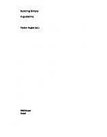
Minimalist tendencies resurface at regular intervals in architecture, bringing with them a return to the simple form. Today, in a time of pluralistic diversity, these tendencies are confronted with other, sometimes contradictory movements, stances and approaches, which exist together in parallel. The exuberant sculptures of a Frank Gehry or a Zaha Hadid, or the numerous blobs inspired by biology, stand in contrast to the retrospective consideration of the simple form, as it expresses itself everywhere at present in the shape of the reduced box. At the same time, ornamentation is being rediscovered, supported argumentatively by Semper’s clothing theory, and being staged with relish. At the same time, such inherently opposing tendencies as simplicity and decoration quite often appear together in the works of a particular architect, or even mix in an individual building. Decorated boxes are an example of this, the most radical exponent being without a doubt Herzog and de Meuron’s forestry science library in Eberswalde, whose facade is completely covered in photographic images. But is it not just the answer to a screaming world of colourful images, to the flood of stimuli and sensual impressions, which lead to minimalist trends? Or the answer to an increasingly complex world, whose deeper lying connections can no longer be recognised by the individual? Minimalist trends regularly are often linked to ethical questions or at least to a particular mentality. However, they sometimes arise (as do many of the sculptural forms) purely from the wish to attract attention or at least to stand out from the loud, heterogeneous environment. The formal simplicity resulting from aesthetic endeavours is rarely also really simple in a technical or economic sense, however. The perfectly reduced form can often only be attained with greater effort. This effort can manifest itself in more extensive design work, but also in an enormous amount of work on hidden details, as is often found beneath the smooth outer surface of a multi-layered wall construction (see also page 10ff.). In contrast to this, building simply in the sense of traditional construction methods means, above all, making do with the locally available materials; that is to fall back on whatever building materials the landscape has to offer, in order to save on transport costs and transport energy. It also means, however, that the load-bearing structure and the construction should be designed such that the available resources can be used as economically as possible and, if possible, that the energy equilibrium is also in order. Building simply in this
sense does not necessarily have to mean doing without all ornamentation, as is demonstrated by the lovingly decorated old farmhouses, which are firmly rooted in their surroundings and whose ornamentation was usually derived from a practical purpose. The examples in this book are principally concerned with small and predominantly economical constructions. It lies in the nature of the matter that many of these have been designed by very young architects, (some of whom were still students at the time). Other examples demonstrate that well established design offices are also taking up the issue. In some cases, the simplicity of these buildings results directly from the brief: in the case of an unheated market hall, for instance, or a workshop building, or a wine store. In other cases the simplicity is more formal. A further group of examples stands out as providing particularly economic solutions to the specified requirements. This is demonstrated by the minimal houses in Andalusia, which the building owners and occupants were able to construct under the direction of the architects without having to provide capital resources, thanks to the simple design and reduced details. The small houses in Dortmund, Dresden and Ingolstadt are also examples of this. What they all have in common is their stance, their concentration on the essentials and their renunciation of any unnecessary miscellany.
1.1
Weekend House on Lake Yamanaka, Japan, 2001; Architect: Kazunari Sakamoto
9
Simply good Florian Musso
Temptation In Peter Weir’s film “Witness”, Harrison Ford plays a divorced inner-city police officer. In order to protect a murder witness, a young boy, from his corrupt colleagues, he has to spend several weeks in an Amish community in Pennsylvania in the USA. A tense relationship develops with the boy’s mother, a widow played by Kelly McGillis. The tension is not primarily erotic in nature. The Amish people live according to a fixed regime. They reject progress. They wish to understand and control their environment down to the smallest detail. There are no telephones, no cars, no alcohol and no violence. Their communal life is strictly regulated. Everything has its fixed place. Modern technology and complex structures are disregarded. The communities are autonomous units without a superordinate structure. Their religion dictates a simple life. “Close to the earth is close to God”. The neighbours get together to build a barn for a young couple. The men build and the women embroider. Everyone knows how things work and they all keep to this. The frame of the barn is under construction. Kelly McGillis hands Harrison Ford, who has turned out to be quite a skilled carpenter, a glass. An opportunity is alluded to: the opportunity of leaving the big city and living a simpler, healthier life. The satisfaction of understanding something. To have found an “ultimate” solution. To have no need to constantly and painfully redefine oneself and one’s world view. To believe in something. To know what is right. To have a direct connection to food and materials without industrial alienation. To belong to a community with a fixed structure. To put things to use rather than use things up. For a long time, regional conditions have shaped the customary structures. Stones are collected, trees felled and a house is built. The roofs near the water are made of straw, those in the woods are made of shingles, in the mountains they are made of stone and in the desert they are made of loam. Everyone knows how to build a house. Materials are practically gratis and the building land too. Labour is cheap. Ornamental elements are time-consuming to make and are used to characterise something special. The construction methods used, within the scope of material possibilities, relate to the climate and geographical conditions of the site. From functional and climatically influenced buildings, a regional culture is formed. Culture becomes tradition, the structural expression of a civilisation rooted to a particular spot. Neighbourly assistance and an economically necessitated
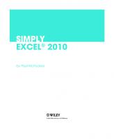
sustainability are facets of this system in the ideal case. Knowledge and understanding of the traditional method go hand in hand with the obligation to behave in accordance with it. Social control and looking after one’s nearest and dearest are two sides of the same coin. The logic of the location is also the logic of the inaccessibility of other locations. The narrowness of ones own horizon guarantees the conformity of the local style. Fixed structures stand for restricted social and spatial mobility and ancient prejudices. In a society with division of labour, this simplicity is lost. Specialisation allows more efficient production processes. Products are measurably more efficient and are available to broad groups of the population. The production of items by hand to meet immediate needs is succeeded by machine production ahead of demand. The place of production is relocated from the family to the factory. This also changes attitudes toward work: the production process for handcrafted works was comprehensible, whereas the connection to the product is lost in industry due to specialisation and the division of labour. Also from a social point of view, specialisation means that it is no longer possible to understand all processes. In many areas a direct connection is no longer present. To have a world view means falling back on specialists and having faith in their relevance. The immediate circumstances of life can be only roughly controlled. An “objective” increase in prosperity is gained by alienation from the simple life. Simplicity loses its natural logic. It becomes an option. The impossibility of the “old” simplicity leads to the inevitable artificiality of every “new” simplicity. This can be justified, but it becomes a Weltanschauung (world view) and is freed from constraints. In the long term, labour becomes expensive and is replaced by machinery. Ornamental elements can be easily manufactured in series production. Decoration is no longer a luxury. As with simplicity, complexity is an option, and it can no longer be ignored solely on the grounds of restricted means. Limits This book shows a spectrum of selected buildings, which illuminate the subject of simplicity from various possible standpoints. The definition of the term is achieved using examples, whose similarities clarify the meaning of the term. Their common and individual backgrounds are important for a better understanding of the approaches. The meaning of the term simplicity is also delimited by the concept of non-sim2.1
Barn in the open air museum in Öland, Sweden
11
2.2
plicity. Simplicity is open to interpretation. It is not viewed as being positive by everyone or in every situation. It can refer to normality. In this case, simplicity would be a particular characteristic. The norm would not be simple. On the other hand, simple can be contrasted with the word complicated. In place of complicated, which has negative connotations, simplicity could also be seen as the opposite of complex. Complex things can be described simply in order to understand them better. The norm can be complicated. The simplicity of normality relates to the pair of opposites: simple and difficult. It is the simplicity of the least resistance. Linguistically, simplicity refers to sentence structures, choice of words and the number of words used. Clear words are joined together to make short sentences. With simple language, the reader registers the words quickly and makes the connections between them in the sentence without difficulty. Simplicity is generally understandable, tangible and clear. A complicated description uses long, convoluted words and employs numerous technical terms and foreign words without much explanation; it is abstract and unclear.1 Then there is “simple” as opposed to compound or with additions. Simplicity also has something to do with quantity. A small problem is often easier to solve than a large one. The Concise Oxford Dictionary also refers to simple as: consisting of one element, all of one kind. Most of the projects described in this boos are small ones. A structure “consisting of one element” or made of materials “all of one kind” would be perceived as being simple. A “simple” hotel is not a normal house, or one that would satisfy the usual expectation of standard service. Here, it can be assumed that the prices lie at the lower end of the usual market price range. The opposite would be a luxurious “palace” hotel. A simple man is not an educated one – as opposed to an intellectual. To make things too simple means to overlook important aspects in the assessment of the facts. The building owner’s simplicity is often different to that of the appointed architect. What does the simplicity of the works compiled in this book relate to? It is a quiet and refined simplicity, which tries to set appropriateness in opposition to the loud manifestations of contemporary architecture. It is a game with options for interpretation; it is encoded on various levels and allows the author to react “sensibly”, whilst still being able to set standards in his work. It can differentiate itself from the socially normal state of things or from the normality of the profession. The spectrum is relatively widely based. The buildings share a common origin as part of a “modern” architecture, in which different aspects are singled out and developed. These did not stand under the heading of “simplicity” in their time. They were developed in other contexts and they will also be discernable in ever new contexts in the future. Recognisable parallels are being further developed with the aid of new discoveries and new materials. At the same time, simple buildings have inherent basic values. Every action is a reaction to what came before. Phases of restriction follow phases of opulence, constellation follows composition, “unexpressionism” follows expressionism.2 These values become compacted into stances. Some of these stances are represented in this book. All stances share the typical perceptions of the period regarding the solution of structural problems, which are closely linked to the basic conditions of the time when they were formed.
12
Values Religion serves as an example of ever recurring concentration on the essentials. Religion forms part of pre-industrialised societies, in which the traditional values were not be questioned. From the puristic concentration on a single God, a multinational organisation has developed, in the form of the church, with a tendency to opulence regarding rites and the formalisation of beliefs. Time and again, new developments in the form of orders, mendicant orders and reformations have taken place, which are almost always related to a simplification in favour of a “pure” doctrine, usually based on the Bible as the essence of belief. Church buildings are also interesting as places of worship, since they are in a position to clarify the subject of structural concentration and internalisation. During the protestant reformation in the 16th century, Calvin, Luther and Zwingli argued for a return to the values defined in the Bible without concern for the traditions of the church. Protestantism, being more hostile to matters of the body and the senses, confronted the opulence of the Roman Catholic religious practices with a puritanical and practical reduction to the bare essentials. In contrast to the Catholic belief, the possibility of purging oneself by means of confession and absolution does not exist. Thus, for example, Stanislaus van Moos sees (German) Switzerland as being a country, which, “with its puritanical inheritance and institutionalised protestant work ethic, has long enjoyed a “special and unproblematic relationship with modernity”.3 The Amish people described in the introduction live within pre-industrial limitations. Their church is laic, non-liturgical and Bible oriented. They have strict rules regarding the style, colour and proportions of their clothing. The men wear simple, dark coloured suits and full beards with no moustache; the women wear simple, long-sleeved dresses with bonnets and scarves. Their furniture has prescribed dimensions. The wood is stained a dark colour to conceal the grain. Door and window frames are predetermined, as well as wall and curtain colours, cutlery, crockery and bed linen. Voluntary limitations come into being, restricting them to a firmly established, modest-moral and healthy way of life. The Shaker sect was less restrictive and more open to development. Shakers try to be economically independent of the outside world. They are known for their diligence and inventiveness; they regarded work as a service to God and quested for a combination of simple, excellently handcrafted and attractive utensils. In their pursuit of economic independence, the circular saw, the ballpoint pen and the flat broom were invented. It is interesting that the optimisation of handcrafted utensils resulted from religious principles. Within the Catholic Church, attempts at reformation have also led to simple building styles. An example of this is the Fronleichnamskirche (Corpus Christi Church) in Aachen, Germany, built in 1930 by Rudolf Schwarz. This church was labelled “God’s factory hall” by his contemporaries and is associated with such expressions as poverty and asceticism, emptiness as the fullness of God, the quiet presence of God, or room for Christian workers. Rudolf Schwarz said in 1930, with reference to the loss of the ”old” architectural iconography, that he wanted to set “a dominant feature in the disorder”. Unlike the previously prevailing historicism, Schwarz is not concerned here with making a radical break in the sense of “new” construction, but with an
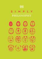
extended “free space between the mandatory and the permissible”, in which the master builder can move.4 Asceticism The idea of asceticism is common to all the examples. The renunciation of pleasures that is practised in asceticism has positive connotations in the system of Christian values due to the focus on moral, as opposed to sensual, aspects. Giving up lesser values should enable higher values to be attained. “All people are pledged to asceticism, to the pursuit of Christian perfection and to practising this with constant progression. On earth this perfection can only be a growing one, to be improved. Its conclusion and full maturity is only achieved in the next world.”5 Before the end of the 19th century, asceticism was related exclusively to the religiously motivated renunciation of consumerism, but subsequently financial prudence and temporary abstinence can be seen to be a result of the market economy. Asceticism had allowed the clergy to concentrate on their religion, but the foundation of capitalist economies lies in investing “savings” and letting these “work” for them. The abstraction of goods in the form of money for potential consumption makes it possible to do without this consumption. In comparison to poverty, asceticism represents the renunciation of consumption by those who could actually afford to consume. The poverty of the priests’ robes is a voluntary curtailment, and the refusal to consume a form of luxury. Nonconsumerism is a form of freedom, assuming one has the means to consume. A choice in consumption also presupposes that the means are available to avoid having to buy the cheapest goods. Those living a simple life can make a conscious decision in this respect. The “new” simplicity is characterised by its option to be chosen. The ascetic moral ideals of the classic utopias create a direct link between happiness and morality. Individual happiness subordinates itself to the harmonisation and improvement of the common welfare. In a kind of forced economy, a moderation of the pursuit of happiness takes place as a prerequisite for happiness. The moderation applies to this life and enables the anticipation of the next life to be even more euphoric. Ascetic moral ideals represent the opposite of the mass gratification of a standardised hedonistic structure of needs. The finiteness of nature, as the area available for the realisation of human happiness, calls the notional boundaries of prosperity to mind.6 Meaning must be found in the limitations, as limitlessness is out of the question. Modern Alison and Peter Smithson see the modern architecture of the “heroic” period as being created by machines: it is cubically formalised, abstract in the interpretation of human activity, a perfect thing in itself, inserted and not rooted to the site, and made of “radiating” building materials. Natural building materials are only used as a substitute for synthetic materials not yet invented.7 This view distinguishes “modern” buildings from the historicised buildings of the same epoch. Machines extend the spectrum of possibilities; the house becomes a machine. 2.2
Fronleichnamskirche (Corpus Christi Church) in Aachen, 1930; Architect: Rudolf Schwarz
13
2.3
2.4
Like a machine, the house is without style and is governed by economic and practical considerations. From a historical point of view, industrialisation resulted from the connection between the economic interests of the middle classes and the progressing field of engineering science. Exponents of “new” architecture attempt to apply this science to construction. They are simplified in form compared to other structures of their epoch, which are designed to a style, heavily influenced by the rules of engineering and adorned with decorative elements. Flush fitted windows, large format window areas and window strips define the facades of the Mediterraneaninspired buildings. Functional elements such as balconies, stairs and exposed bearing structures are compositionally arranged according to theme. “We know no forms, only construction problems. The form is not the goal, but the result of our work. There is no form as such.” And “Building art is the will of an epoch translated into space; living, changing, new. Not yesterday, not tomorrow, only today can be given form. Only this kind of building forms. Create the form out of the nature of the assignment with the means of our times. This is our task.”8 In this statement by Mies van der Rohe it is clear, that the “new” construction is seen as the clarification of social development. Even though Mies assumes more rationalistic stances later (similar to those of A. Behnes), the relevance of form derived from technical considerations is invoked as an adaptation to social reality and “modern” objectives. Minimum Resulting from apparently inadequate living conditions in the lower classes of society, the cooperative building societies and in the factory housing of committed employers, a tendency developed after the First World War, which attempted to formulate an architectural “subsistence minimum”. In contrast to the “free” housing market, the most important requirement here is to secure a minimum standard, affording human dignity and the necessities of life, even where the economic capability is insufficient. The projects are usually publicly funded. These approaches can still be discerned in the requirements of publicly fundable housing today, in which the desired ideal standard, with regard to function and living space requirements, is defined in guidelines. Simple solutions are propagated to achieve a subsistence minimum. A minimum means by definition that it cannot be simpler. This also tends to result in reproduction without differentiation, which can be seen in many examples. The simplification of the architectural form corresponds to the standardisation of the assumed needs. Differences become noticeable in two fundamental directions, one of which associates the nationalistic-romantic image of the “simple life” with the subsistence minimum (cf. Tessenow) and one which attempts to use the potential for progress in the industrial manufacture of “modern” materials and “scientific” design methods. Architects are concerned here with simplicity and direct functionality. A subsistence minimum apartment represents the orientation towards “small” construction tasks and satisfying elementary needs without regard for exercises in style. Understanding In contrast to the “heroic” vision of modernity, “simplicity” presents itself, under the premises outlined above, as a rec-
14
onciling link between locally rooted tradition, bound to the rules of civil engineering, and an internationally operating, abstract modernity. The aesthetics of the “Palais de Bois” by A. and G. Perret at the Porte Maillot in Paris, built in 1924, arise from the structural layers of wooden rods and contrast a structural simplification with the simplification of form, without reference to the repertoire of historicising forms. With its pragmatic structure, this temporary building is reminiscent of industrial buildings with optimal natural lighting and structural design. In his German building projects and designs, Mies van der Rohe makes direct links between the materials used and the architectural form. The office building made of reinforced concrete, high-rise buildings made of steel and glass and the brick built houses are all formally derived from the structural possibilities. The demonstrative display of exquisite natural stone surfaces shows the effect of materials as a constituent part of architectural composition. In le Corbusier’s work, the shift of interest from the industrial phase (although this was often compromised by inferior construction) with its “radiating” surfaces to the handcraft-dominated works in the Loucheur houses, built in 1929, can be seen. Here, residential units were produced in series and combined along a wall made of natural stone to form semidetached houses. The optimisation of the typified industrial product is contrasted here with the local associations of the masonry wall made of stone. In brutalism, whose heyday was between 1953 and 1967, handcrafted raw (brut in French) materials were often put on show. The construction phase becomes part of the design repertoire. Materials come to the fore, which would previously have been considered unfinished or poor: raw bricks or concrete, unpainted wood, or steel. Not industrially perfect, but handcrafted and solid, with the visible traces of human labour. Not smooth and refined, but raw and rough. The visibility and comprehensibility of how the structure carries the loading, how it functions and how it was constructed is important here. In Alison and Peter Smithson’s Hunstanton School, built in 1954, the sanitary installations show the route that the water takes in tubes and open channels. In “Without Rhetoric” it is later claimed that the core of the statement must be reached without rhetorical additions, since the expression of power is no longer relevant within a society that is opening up in all directions.9
nois Institute of Technology’s10 prospectus shows the mutuality of traditional construction methods and modern approaches, which have the logic of the structure in common, developed from the various materials.11 The simplicity of functionalism is bounded by the return to handcrafted and conceptually precise structures, in which clarity and truth are manifest: “Let us lead them into the healthy world of primitive building methods, where there was meaning in every stroke of an axe, expression in every bite of a chisel. Where can we find greater structural clarity than in the wooden building of old? What feeling for material and what power of expression there is in these buildings!”12 Geometric In Edward L. Barnes’s Heckscher House, built in 1974, the form of the building has been repeatedly reduced, firstly by breaking up the system into several tiny building units. Between the buildings of the “hamlet”, external space is created, reflecting village life. Secondly, the roof and facade are uniformly clad using shingles. A reduction down to the symbolically placed image takes place, without being compromised by a self-manifesting construction method. The geometry of the building with its roof sloping at 45° is as a child would draw a house. It is not the minimum achievable roof gradient for the material that is important, nor the structural arrangement dictated by the various demands on individual components, but the unification of the design components. This formal simplicity is the antipole to economic structural simplicity. It is not functionality and the logic of the arrangement that define the essence of the building, but an image that is also in one way or another habitable and buildable. If the expression of the logical construction cannot be taken into consideration in the appearance, there is a danger that functional and technically suboptimal solutions will be applied, for the sake of the form. 2.5
Less In Mies’s “less is more” postulate there is also a claim to happiness through asceticism. More concentration and depth should be achieved by using less elements of form and a simpler design. The “search for clarity” finds an answer in the reduction to skin and bones and the straight lines of their arrangement. Here, less means a necessary minimum, but also an achievable optimum. The benevolently ascetic will to create art allows the work to be seen as both tangible and metaphysically withdrawn. Mies’s interest in traditional building forms is striking. The Illi-
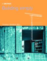
2.3 2.4 2.5
Loucheur houses, design, 1929; Architect: Ludwig Mies van der Rohe Terraced housing for war veterans, Raegnitz developement near Dresden, 1919; Architect: Heinrich Tessenow Plumbing in the Hunstanton School in Norfolk, 1954; Architects: Alison and Peter Smithson
15
Regional Since Russell-Hitchkock and Johnson declared the “international” style in 1932, architecture’s regional connection has become a topic in discussions regarding the style of architecture suitable to industrial society. Conscious concessions to regional typicality usually involve picking up on historical manifestations, without being able to incorporate the sense of the form into the imitation. Glazing bars divided up the window areas due to the small dimensions of the available panes. Today these bars are available as an option with double glazing, placed in the airspace between the panes. The materials used were dependent on the regional availability. Today, this availability is not always on hand. Stone quarries are being closed, timber is cheaper from abroad. So it is usually senseless to take on the forms of historically developed building types without questioning their rationale. A poorly understood copy of old buildings, without clarification as to the living styles and construction forms of the present, destroys the spirit of this architecture. Here, the architecture of economy offers interesting approaches with reference to the dichotomy of traditional content and modern form. Particularly in rural areas, little is superfluous and many things are simply designed. A well understood interpretation of values and of the method that forms the foundation of these architectural styles allows for a procedure that is related to the context and has direct reference to the cultural basis.
2.6
2.7
16
Economical The economy principle is concerned with achieving as much as possible on a given budget, or meeting a target using a minimum of resources, limiting the expenditure of funds, energy and land. Within the framework of an economically founded aesthetic, the imperative of using less means can be extended to all architecture. It can refer to the use of financial as well as creative means. In practice, optimisation aimed at achieving the highest possible quality creates problems. Investing the least amount of money is not synonymous with a formally simple solution. Nor is “simple” synonymous with little effort. A simple form can be a qualitatively stronger resource than one that is complex. Not everything that looks cheap is cheap. The qualitative aspect of architecture can indeed be a development goal, but it is difficult to optimise in the sense of a design economy. In reality, simple construction posits a particular quality by means of limitation, but it cannot be linearly extended to apply to complex solutions. Under favourable circumstances, simplifying is a means of reducing costs. Ecology is a special form of economy. It is a biological term denoting the interdependency of organisms and their environment. Ecology can be interpreted in different ways with reference to simplicity in architecture. It is generally concerned with an optimisation process, which is related to the consumption of environmental resources, and in which buildings play an important role. The more technically-orientated tendency assumes that, thanks to technical developments, an environmentally friendly life style need not be associated with having to do without, whereas the religious, technologyhostile and ideological tendency preaches limitation and economy. Both tendencies are interesting regarding the subject of simplicity. By the reduction of needs and consumption, the disruption potential of buildings with regard to equilibrium in the environ-
ment can be reduced. The law of economy should lead to a specific (passive) architecture that uses resources sparingly. Technical systems are simplified or omitted. Unfortunately, ecological approaches are rarely linked to formal reduction and comprehensible simplicity, as the emphasis is placed elsewhere and this emphasis also has to be demonstrated. The subject of economy can also be considered from an ethical standpoint. How much will unwritten generational contracts allow us to consume? How can the satisfaction of using a well designed product for many years be justified, in comparison with the quick consumption of fashionable consumer articles, when it goes against all economic reason? Ordinary The German-Swiss architecture that represents “new simplicity” can be seen as setting boundaries in two directions, distinguishing itself from the opulence of the Ticino architecture in the south, as well as from the technically expressive German architecture in the north. The relationship between object and image is abandoned in favour of complete concentration on how the object can be experienced.13 The simple and the banal then become the basis for more profound experiences. Sensuousness is first made possible by a desire that is independent of the motives of sensual stimuli – by morality. Concentrating on the object as an entity of experience intensifies the experience itself. Abstraction and banality serve as a background to a more profound experience, which sees itself as a new beginning based on what went before. Marcel Meili observed that he possessed an “anti-symbolic reflex”: “in connection with these intentions, the stylistic limitation, if not to say asceticism, has a meaning in many projects. But the linguistic rigorousness only barely allows a glimpse of the process. Ultimately it still remains a morality of form, in which the aversion to the exquisite and the original encounters a fascination for brusque directness.”14 “Arte Povera” and “Minimal Art” illustrate this method. Here the attempt is made to define basic values within the framework of a new beginning in art. Formed in the early 1960s as a counter movement to “degradation and crisis” in the form of abstract expressionism, it is characterised by freedom from valuation and by the geometric sequencing of similar, simple, sometimes banal elements that have been reduced to “basic forms”. Germano Celant summarised these attempts with the term “unexpressionism”.15 In this case, the banality of the norm is not normality itself. It develops into a strategy in relation to the extraordinariness of the ordinary. Where artistic expressionism mutates to normality, the “new” simplicity becomes a conclusive reaction. Referring to Celan, Steinmann sees the intrinsic value of the experience as being an unavoidable consequence: “The observer experiences something, which is the experience itself or is the way in which it is experienced.”16 It is not primary simplicity that is important, therefore, but the background for more profound experiences such as the sensuality of the materials used. Banality, in this sense, can be seen as a “subversive strategy”17, which allows double readability as an image of normal architecture and as its sublimation. Clear Consciously simple building also certainly represents a need for semiotic clarification. Semiotics is the philosophy of the meaning of terms. Language has always been both a means
of communication as well as a field of experimentation. In sub-cultures, words are used outside the original context, for example “dough, bread, gravy” for money and “cool, wicked, ace” for good. In this context, simple can also mean that a roof is a “roof”, a wall is a “wall” and a house is a “house”. A house in the country should be identifiable as such, according to this logic. It can also mean that if the meaning is unclear it is better to say nothing. The fundamentals become a moratorium on the path to generally comprehensible statements. Small Many of the buildings described in this book are small, some very small. The scale opens up possibilities, which would not arise for large projects. The whole can be developed without the problems of repetition such as beginning and ending, and can be an entity in itself. Construction using a single material is easier. It is also easier to take risks. Simpler technical requirements are made of small buildings in comparison to large ones. Using simple processes, small elements and structures that can be erected using hand-construction methods, it is possible for the owner to build it himself. This is evident in timber construction as well as with recourse to “primitive” building methods such as loam construction. This puts the amateur on the same level as the specialist, who still has to develop the technology. The self-help aspect is particularly evident in Walter Segal’s buildings. He has developed a system that is available to the layperson and which makes use of small-format, standardised building materials based on the dimensions of the materials available from retail outlets. The form created in each individual case is accepted as the “result”. Large On a large scale, the routes to simplicity change. Series products are brought together in uniform images to form components. The brick structure of a wall does not direct the attention towards the individual element, it becomes a texture. If the building goes beyond a certain scale, this tactic can be transferred and applied to the whole building. Various hierarchical levels of readability are created. Series production is one of the foundations of industrial efficiency. The repetition allows the optimisation of the manufacturing processes for the individual part. In the same way as repetition in industrial production enables the production of large quantities of products, repetition in building facilitates the comprehension of large buildings. In contrast to industrial products, which although they are manufactured in series are sold singly, repetitions in construction are brought together in a single building. Herein lie the potential and limitations of repetition. Unification can make a composition more comprehensible only if such a thing exists. If the repeated element is of high quality and attuned to character and proportions of the building, this can have a positive influence on the overall quality. The complexity of the sum of the individual problems is then reduced accordingly. Unification also means treating equally things that are not quite the same and even things that are different. As with all human activity, the conciseness lies in achieving a perfect balance in the judicious degree of utilisation. 2.6
Heckscher House, Mount Desert Island in Maine, 1974; Architect: Edward Larabee Barnes
17
Norm Many of the buildings shown here are not “normal” and often do not correspond to the norm. Norms allow dependable statements as to the condition and behaviour of building components and structures. They are standards that, once defined, do not adapt to specific situations and which become out-dated with time. Sticking to the standards simplifies life and offers protection against liability claims. Increased demands on the performance of building components lead to standardised construction. Standards define the expected and the safe. To make headway in the market for quality architecture, an architect must publish his works. In order to be published, the building must be “interesting”. But interesting is not the expected. At the same time, as a part of the process of “branding”, the architect’s personal design method or style must be introduced as his trademark, independently of the specific task. To increase the sententiousness of the desired images, they are made to look as striking as possible. The ascertainable, and the purity of the message, play a role here. Normality on the other hand is related to norms and standards. A critical examination of standards requires thorough knowledge of their origins. The desire to send a simple message often stands in opposition to standardised construction. Here also, the scale of the works represents the key to simplicity. Reduced demands and a smaller and more easily calculable risk factor make border experiences possible, which are problematic in larger projects.
2.7
18
System Systems (derived from the Greek ‘sunistanai’, meaning to stand together, to combine, to join) are models of reality, constructed to be as functional as possible. As organising structures they correspond to the priorities of a designer or observer in a particular context. The combined components or sub-systems of a system stand together in relationship with each other. If they influence each other the relationship becomes a connection. The connection of the elements determines the characteristics of the system. Conversely, the structure of the system exerts a controlling influence on the elements. The system makes comprehension possible by the creation of hierarchies. A complex connection is made comprehensible by displaying its structure, its architecture. Systems become interesting where the size of a task limits its manageability. The system is an attempt to formulate complexity ascertainably. The fewer components the system has, the more time can be spent on solving the individual problems. The quality of detail achievable within a given time is directly dependent on the number of system components and the complexity of the connections that exist between the elements. The larger the series of the designed elements is, the better the possibilities are for developing original subsystems that are not available on the market and for achieving a more fitting, and therefore more elegant, solution. Paxton’s Crystal Palace shows that the reduction of details and element types can result in a short construction period and pertinent details. The whole facade design for the building constructed for Willis Faber Dumas in Ipswich by Foster Associates (1971–75) can be described by a single detail drawing; this detail was developed in cooperation with the best specialists. New procedures were tested here, such as
independent glazing, glass fins to take up wind loads, and minimised glass mounting brackets. The limits of the system ideology emerge where building systems are not used as part of the optimisation of a design, but where the design arises out of the inherent restrictions of the use of the system. Concept Falling back on existing sub-systems can ease the production process in various ways. A prefabricated window can be accurately assessed with regard to its performance and functionality. The American 2 x 4 frame construction system enables the stock-keeping of standardised timber sections, planks and jointing materials. The system is commonly understood and the calculations can be simplified. In the field of construction, industrial production applies predominantly to material systems: industrially produced semifinished products and sections are combined to order using handcraft skills, to form elements of a particular size or to create buildings. Elements or sub-systems combined to form functional units can be organised comprehensibly in a concept. They no longer require the understanding of the specific characteristics of the element, but require knowledge of the integration of the sub-systems in the whole scheme. A double facade is perceived as a single, homogeneous design component. As a technical building unit with specific dimensions, it combines complex individual elements to create a single formal element. At the same time it is made up of individual parts that are repeated. The formal and structural complexity is met by integration on the one hand, and by repetition and creating uniformity on the other. Clear concepts bring order to a complex problem. The concept is a caricature of the interaction of the systems within the design. It is not a system in itself, but the plan for its use. Concepts link formal and structural simplicity to architecture. In a concept, systems are organised, with high quality detailing, to provide quality of space and comprehensibility. It is simple architecture, in particular, which gives architecture the appearance of being an organisational problem. Poles The examples published in this book show a spectrum of possible approaches. They mostly refer to relatively small and manageable construction projects. Some are provisional and lay no claim on eternity. Many of the examples are also influenced by the reducibility of the requirements. Through the definition of the task or rather the interpretation of this definition by the designer, they provide an opportunity for developing either simple forms or technically simple solutions. The simple forms are smooth and abstract. By concentrating on the simplicity of the form, the structure takes a back seat. Complicated or even technically questionable constructions are then tolerated. A curtain wall can unify and conciliate a varying and formally restless facade. This must be designed, constructed and paid for as an additional layer, however. A cubic building will seem even more cubic if it has no plinth detail or parapet sheeting. The concretely pictorial examples see, in the structure and materials, a design potential to be integrated. The resulting architecture is influenced by the construction process, the materials and the structural requirements. The possibility of developing a formal logic from the quality of the material and its assembly is picked up on. The simplicity
of the structure and the readability of the assembly, loadtransmission, moisture protection and other functional aspects are not concealed. The availability and logic of the industrially manufactured products are also determining factors in the formalisation process. The outcome of a process and not a predefined result is what is sought here. The renunciation of radicality in both directions promises good results: the structural design potential can also be demonstrated without expressively coming to the fore. Evasion Simple construction in the framework of the above mentioned approaches can only be applied to the objectives relevant in each case. However, tactics can be distilled, which are common to several of the examples shown. Evasion is based on the tactic of avoidance. It presupposes an exact analysis of the problem that is to be solved, as well as good knowledge of the possible solutions. Instead of solving a problem by using a (standardised) standard solution, the particulars of the task and the site are used to arrive at simpler solutions. To make the same demands of a house built in southern Europe as of a German house would neither meet the structural requirements nor be appropriate to the regional building culture. For a building with a specific purpose, such as a wine cellar, the building shell will not have to meet the same requirements as for a residential house; this means that a particular structural solution can be found to suit the particular agenda in this case. Fahr’s window system in the HL-Technik building in Munich illustrates an attempt to simplify the window frame construction. By limiting the fenestration to a tilting window, which is arrested by means of a sash fastener, the usual window sashes could be replaced with a simple Z-profile. Determining the requirements that need to be considered makes the simple solution possible. The solution of a structural problem can be its avoidance. A wall that is offset from the floor needs no plinth. The design concept for the building, and the materials and details used, can provide better opportunities for building more simply than usual. Setting fewer requirements makes it easier to fulfil these outstandingly. It can also happen, here, that secondary problems are brought to the fore, which can then be simply solved. A wall construction can look simpler if it does not serve a thermal function than if it does. If a supporting structure is replaced by a wall, it is possible to create a simple wall construction in place of a “normal” supporting structure. Material Martin Tschanz pointed out that simple architecture, in particular, permits unusual materials and unusual uses of materials. This effect, referred to as “sensual ambiguity” in connection with German-Swiss architecture, is based on the concentration on essentials, which has already been mentioned.18 Construction is not a way of conveying meaning. The attention can be concentrated entirely on this presence. Exposed materials used on large areas can be tested for sensuality, or as Christian Sumi formulates it: “Away from the material, towards the effect”.19 Here, the familiar or simple form is experienced in a new material, rather than a new architecture being formulated from the characteristics of the 2.7
Offices for Willis, Faber Dumas in Ipswich, 1971–75; Architect: Norman Foster
19
2.8
new material. It is a case of the “gentle” perversion of an “ordinary” reality. The use of a uniform covering material for the facade and the roof can create additional irritations. The conventional use of different construction details and materials no longer makes sense in the new context. The use of transparent cladding materials shifts the category of “openings” from the windows to the building skin. In the context of innovative “misappropriation”, an apparently worthless material is refined by means of careful application. Perfectly aligned cast iron units, similar to the covers of sewer inspection chambers, become a house facade. Loam is compacted by ramming to define a place of worship and tranquillity. A material known for its use in home-made buildings in the third world is modified with concrete, perfectly implemented, and demonstratively transplanted in the first. An industrial building system is used in an atypical situation and takes on a new meaning. The simple serves as a carrier for the valuable. Transparent Transparent building materials have progressed. Using coatings and gas-filled units, triple glazing can achieve the same insulation values as lightweight, vertically-perforated brick walls. Point fixings allow glazing to be fitted without frames. Using laminated glass, shatterproof glazing can be achieved as well as the exact adjustment of colour and transparency. Sun protection technology can be provided by spectrally selective glazing, by vaporisation, or in the form of adjustable louvres that are variable and maintenance-free, integrated between the panes. These developments are important in various respects. Transparent skins give the impression of a veil, abstract and freed from their frames. This goes for synthetic cladding panels as well as for glass facades with point-fixings. They enable components that appear to be complicated from a functional and practical point of view to be combined in a simple volume. The transparency allows various readings: as an independent “volume”, for instance, or as the thermally low-maintenance cover for a comprehensibly portrayed functionality of the building and its components. The uniform skin of the double facade and atria smoothes and simplifies. The semi-transparency, comparable with a negligee, which can be achieved with transparent materials, is a literary interpretation of the facade as a carrier of the interior. A second aspect is also important. Transparent materials are necessary in any case to allow daylight into the building. If then a reduction in the number of different materials is required to create a simpler design, glass facades present themselves as an obvious option for achieving uniformity. By the suppression of parapet details using glazed roofing units and the avoidance of plinths, the glass cube seems even more absolute. In the facade of the Allianz Arena in Munich, the cushion structure of the stadium roof is continued down over the concrete facade of the stands. The building looks rather like a lantern. The translucent skin increases the symbolism by creating uniformity in its appearance, but it is not necessary from a technical point of view. Through the need for abstraction, facades are simplified and window openings are more clearly formally defined. They are often flush with the surface of the facade so that the building appears homogeneous, without recesses. Sometimes they are flush to the interior wall, set deep in the embrasure so
20
that they appear as a “hole” without a frame. Fixed glazed elements enable simplification by increasing the size of the uninterrupted window areas and simplify the frame design. Specialisation Whereas aspects such as comprehensibility, structural honesty and readability of the functional connections were related more to the bearing structure until a few decades ago, the structural properties are diminishing in importance today, due to increased demands on the performance of the building envelope and the interior fit-out. After the 1960s and ’70s concentration on the auxiliary functions of the facade in the form of facade grilles, which were justified on the grounds of sun protection, escape and cleaning access and were used by Sepp Ruf and Egon Eiermann, for example, that which is visible has a more symbolic relationship with a static-structural “reality” today due to the necessary thermal separation. Martin Steinmann describes a “veiling”, which focuses the covetousness on the veil itself, but on the other hand leads to the buildings becoming only shells, where that which is veiled loses meaning.20 Specialisation is used in wall constructions to improve the performance of the whole construction. Special materials assume specific functions such as insulation, load-bearing and cladding. Specialisation is also relevant to the planning process as a whole. Engineers, project managers and site supervisors offer parts of the planning process as separate services, and the design itself is divided into increasingly smaller sections. Lighting designers, decorators and kitchen studios testify to an increasingly professional approach by means of specialisation, but also to a latent loss of control over the planning process on the part of the architect. In this case, simplicity is based on architectural objectives, which question such specialisation. By means of simplification and by creating simple themes, the specialisation that makes experts necessary should be avoided. Thus, questions become important, which relate to the wholeness of the building and which cannot be segmented and solved by specialists. Fair-faced concrete interiors need no decorator and solid facade constructions need no facade engineer. The necessity of the connection to the “reality of the building site”, which Martin Steinmann recognises as a feature of the (simple) German-Swiss architecture, thus becomes comprehensible.21 Solid Aris Konstantinidis’s holiday house in Anavyssos, built in 1961, shows a concrete ceiling placed on top of masonry walls made of natural stone. The windows and finishings become secondary, as in Louis Kahn’s buildings in warmer parts of the world. This building embodies the archaic and a simple modernity as few others do. Stone is linked to heaviness and constancy. The surviving witnesses to early human buildings are almost always made of stone. Natural stone is heavy. Due to its weight, it was traditionally used near the quarries and contributed to the regional style of building forms. The “thousand year” buildings of the Third Reich in Germany were built of German stone. The question of constancy is often brought forward as the deciding criteria in the selection of facade materials. In existing examples these characteristics can rarely be proven. The increase in material costs leads to the use of a minimum thickness of material, often just a few centimetres
thick. Using fragile pins, the thin facing panels are fixed to the console structures, which are developed according to the considerations of building physics. Black joints between the panels stand more for incomprehensible weightlessness and immateriality than for logical load transfer. Damage due to vandalism is often found at the base of walls in urban areas and this bears witness to the fragility of the constructions. Stone supply contracts are tendered internationally and the stone is brought from far away: from India, China and Brazil. The use of the material is not comprehensible, therefore, and does not correspond to traditional ideas with regard to the material. This justifiable but unsatisfactory “normality” can be avoided in various ways. Increasing the thickness of the cladding material to that of a facing wall, as was done for the new Pinakothek in Munich, resolves some of the weaknesses but increases the construction costs. Concrete frameworks infilled with dry stone walling as in Herzog and de Meuron’s Casa de Piedra in Tavole built in 1988, or rock-filled gabions as used in the Dominus winery in Yountville, USA, built in 1997, attempt to re-establish the disputed logic between material and form, in that the load-bearing function of the stone is unmistakably relinquished. The solidity of stone structures is shown to best effect where the aspect of the complementary division of tasks in modern building technology can be circumvented. In France in the 1960s, Fernand Pouillon constructed buildings with solid natural stone walls, which also seem to have been financially competitive in a housing market dominated by prefabricated building techniques. Building without the use of insulating materials, in the style practiced by Pouillon, is not an option today, however. Solutions such as the wine cellar by Gilles Perraudin, introduced in the examples section (seee page 114ff.), use the opportunity presented by a particular programme to comprehensibly reconcile the archaic tectonics of stone walls and wooden beams with the functionality of the building. A dichotomy between the demand for solidity and a contradictory application also has been observed for artificial stone masonry. Growing requirements for insulation in external walls lead to different ways of adjusting masonry construction to the current needs. Thermal insulation composite systems are common, which allow the external appearance of a largely joint-less and solid building unit. The “rendering” materials used, however, can no longer absorb sufficient moisture. The visible coating is a hollow sounding, sealed membrane, that is exposed to high thermal stresses. Some manufacturers try to offer stone wall elements with increasingly improved thermal insulating properties for use in single layer walls. The thermal performance of theses stones is improved by the use of insulating inlays and pore-forming materials. The construction of new buildings using salvaged bricks, as was seen after the last war, is no longer conceivable with these types of stone, however. They become ever more vulnerable and can therefore only be reused as building rubble. The “system” rendering applied to the masonry is compatible to the masonry and relatively soft. The bricks are exposed to strong thermal stresses. In attempting to retain the original quality of the material under changed circumstances, its character as a solid and durable construction material is lost. 2.8
Holiday House, Anavyssos, Attica, 1961– 62; Architect: Aris Konstantinidis
21
Other constructions envisage external walls made of complementary, structured layers, each serving a different function. An internal cladding layer is followed by a load-bearing layer, which is followed by an insulation layer, which is followed by an air space and an external cladding layer. The cladding in such constructions is often subject to high thermal stresses. This results in the need for expansion joints, ventilation and drainage openings, fragile wall anchors and horizontal support brackets. The aging of the insulation embedded in the middle of the wall cannot be subsequently checked. A return to uniform, solid wall construction as an attempt at achieving simplicity must be considered here. The Brühl school building in Gebenstorf, designed by Burkhardt Meyer & Partner and built in 1996, has a solid wall construction (composite masonry made of facings, lightweight verticallyperforated bricks and air spacing), which is contrasted with a glazed corridor area. The vocabulary is reduced for clarification: light and heavy. The brick wall appears to be solid. The 50 cm-thick wall construction does not meet the highest insulation requirements (U = 0.38 W/m2K). But then again, the wall is made only of bricks, mortar and internal rendering.22 Concrete Reinforcement, pre-stressed elements and other materials can be integrated into a concrete component, which from the outside appears to be a single unit. The consistency of the concrete can be made to suit the individual demands, without this being apparent on the exterior. By adding porous aggregates such as pumice or foamed glass, light-weight structural concrete with insulating properties can be produced, which still maintains a residual bearing capacity. Building services systems such as pipe networks can be embedded; in this way they are not visible and have gained meaning in the context of the “thermal activation” of components. The heat transport media do not only contribute to the formal simplification of the building by virtue of their invisibility and the reduction of visible components; they also allow a more relaxed attitude with regard to the fear of overheating in the summer, which can present a problem with simpler facade constructions. Since the activated components should be in direct contact with the interior air, interesting arguments arise in favour of leaving concrete surfaces raw.
2.9
22
Due to developments in formwork techniques directed at reducing labour costs, the visible surface has developed from being raw and rough to having a perfectly smooth appearance, structured only by form anchor holes and formwork joints. Concrete walls tend to be statically over-determined. For normal concrete a single column would usually suffice to carry the dead load. Newer trials are therefore directed towards frameless or load-bearing wall constructions on the one hand, or a reduction of the load-bearing capacity by adding light aggregates on the other. The simplification of the appearance, by making use of the load-bearing function of an element that is required anyway, was the consequence in the case of frameless load-bearing panels. By adding light aggregates, the concrete wall can have a monolithic structure. Some of the costs incurred due to formwork and building physics problems in a layered wall construction are avoided.
The integrative possibilities of in-situ concrete tend to be detrimental to the poetry of comprehensively constructed buildings. Prefabricated parts, on the other hand, are particularly suitable for series production due to the high cost of moulds. Industrial production makes high precision prefabrication possible. Load-bearing structures made of prefabricated concrete show how the loads are transmitted through largearea bearing surfaces and a clear hierarchy of load-bearing ceilings. The manufacturing processes can be discerned from the pattern of the joints. In the Bauzentrum (building and construction centre) in Munich, the screw connections of the facade elements enable the fragility of invisible facade mountings to be avoided (see page 152ff.). Textile reinforcement and high strength concrete open up new possibilities with regard to the thickness of pre-cast concrete elements for use as facade cladding. Wood Since the “primitive hut”, wood as a building material has served as the bending resistant component in buildings. Today, wood as a construction material is emerging in new forms. In the Kochenhof housing development in Stuttgart, which arose as a reaction to the Weissenhof development, wood still played the role of a countermovement pitting “German wood” against “modern” building materials and houses built in the “international” style. But after the war wooden building components developed to form a wide range of industrially manufactured products with versatile application opportunities. The dimensional stability and the shrinkage and cracking properties have been improved in the process; also wood can now be bonded to form crosslaminated or parallel-laminated panels and beams, which can be loaded from all sides. The “American” timber construction method known in Europe as timber frame construction demonstrates a new type of simplicity. From the skeleton structures that were common in the 1970s, such as the prefabricated Huf houses, a “structureless” construction was developed, whose functional components disappear in the envelope of the wall construction. A “wall rationale” takes the place of the “skeleton rationale”. A functional specification can be prepared for the structure so that the individual bidders can prefabricate the parts according to the manufacturing facilities at their disposal. Laminated timber slabs, board stacks and composite constructions also generate new structural possibilities. CNC (computerised numerical control) milling cutters enable visually simple (dove-tail) joints to be made, even by smaller companies, without the need for metal connectors or nails. Wooden components tend to be limited by fire protection requirements, weather and acoustics. If these limits are exceeded, the construction then becomes complicated. In wooden structures, as with other types of structure, simplicity is possible where the material is used in accordance with its characteristics and limitations. The wooden structures shown here are one to two-storey buildings and have simple requirements. The market hall in Aarau, (see page 74ff.), is an open, unheated space defined by wall constructions. A sprinkler system is installed in the roof space. For the crossbeams 2.9
Placing the natural stone blocks: Résidence Le Parc, 1957–1962; Architect: Fernand Pouillon
23
and plinth areas, trust is placed in the weatherproof qualities of the Douglas fir used for the construction. Freed from functional restraints, the wall and ceiling structures can be designed to be clear, simple and elegant. The archaic quality of the wooden beams in the wine storehouse in Vauvert, (see page 114ff.), compliments the weight of the natural stone walls in a classically demonstrative way. The small sauna in Finland, (see page 70ff.), follows the unbeatable woodenhouse-in-the-woods logic. It reacts to the wood’s sensitivity to water with an overhanging roof and demonstrates the hierarchy of its structure openly and comprehensively. The uncomplicated processing of the wood by means of sawing, milling and drilling and the many forms of its commercialisation give the architect great autonomy with regard to the design of the details. Wood insulates only 3.5 times less efficiently than special insulating materials and therefore allows penetration of the thermally specialised layers. Wood is easy to sever and reconnect, and due to its light weight can be used for do-ityourself construction. Wood is useful in smaller construction projects where homogeneous building materials are desired. It can be used as a load-bearing material and for interior and exterior cladding. Different types of wood with strong grain definition can be made more uniform by deconstruction / reconstruction, rough saw-cut finishes and paintwork. The use of wood as a continuous material for both facade and roof can be found in traditional shingle architecture and in newer experiments using boards.
2.10
24
Steel Three factors delimit the range of applications for steel in buildings: fire protection, thermal insulation and small grid floor-plan arrangements. The restrictions are ascribed to the character of the material. The structurally efficient, but heavy and expensive material is commercially available in the form of profile sections and sheets. These present a large target area for fire and a relatively small material thickness. Steel is a good conductor of heat. Partition wall connections present a problem due to the angled geometry of the profiles. “Economic” steel construction has its own logic. According to “European” steel construction logic the welding is done in the factory and the bolting together on site. Head plates, joints and connections are easy to assemble, geometric but complex. Not without reason were Mies van der Rohe’s steel structures welded. The sculptural simplicity of his buildings could not have been achieved with the expressivity of bolted fastenings. He uses the “American” steel construction logic of welding on site. In contrast to the principle predominant in America, whereby the structure, facade and interior fittings are kept separate, he leaves the steel visible where possible and carries over the theme of the building’s structure into the facade. Steel structures can be left without cladding in warmer climates, creating structures that give the impression of being light. In climates with cold winters, the emphasis shifts from the structure to the building envelope. The artificiality of the facing arises from the necessity of the envelope. The load-bearing effect can be made recognisable by using symbolism in the cladding, in the style of the Mies corner, or made visible through transparency. Weather resistant and chrome-nickel steel can be welded on site and used universally. The bridge extension over the Frödisch, (see
page 130ff.), discussed in this book is a simple Z-section, drawing no attention to its components. The railings, structural elements and walkway are fused together by virtue of the uniform material. Steel construction is commercially successful for light, widespan structures such as business premises. For these buildings, which are usually no more than two storeys high and have gently sloping roofs, few partition wall connections, and facades clad completely with metal panels, the above mentioned reservations do not apply. The resulting aesthetic tends to be pragmatically appropriate to the circumstances with the aim of reducing costs. Transferring this principle to housing structures lifts the division between the worlds of work and leisure somewhat and contrasts the “fixed” idea of detached house construction in the suburbs with the austere logic of factory hall construction, which rejects misplaced romanticism. Simply good So, the search for simplicity turns out to be an ever recurring new beginning. Reflecting on the essentials is a reaction to specialisation in an industrially influenced society. Small, manageable units are promoted, on the one hand, whilst large units are simplified by systemisation on the other. The architect’s need to clearly explain stands vis-à-vis the interested observer’s need to understand. Reduction to the essentials not only decreases the level of complexity of the structure, but strengthens the role of the architect in the diverging construction process. It should be anchored in the architect’s professional philosophy to search for the simplest solution to a given problem, not acting as a cost-reducing “service provider” but as an expert employed by the developer to protect his interests within the framework of a definite concept. If the term “simplicity” is viewed broadly enough, it is concerned with the visual and financial economy of means whilst striving to reach a given goal. The pursuit of simplicity is based on a normal state of affairs. Architecture has to do with normal banality on occasion, but not with normality. It attempts to break the mould of normality using intelligence and care. It will always remain an elite endeavour. Since the problems to be solved are so complex, simplicity can only be formulated as an unattainable goal. Differences exist in the degree to which the term simplicity is intellectualised. Generally speaking, simplicity is always intellectualised, as the old simplicity can not be recreated. In this sense, art can not be avoided, but it can be good or bad. Ultimately, simplicity is a question of carefully planned action. Peter C. von Seidlein states the common aspect of his buildings as being: “The irrefutable desire to use new discoveries, new materials, and that means nothing more than to follow forward-thrusting technology with “reason, the first principle of human actions””.23
2.9
Bibliography 1 Langer, Inghard; Schulz von Thun, Friedemann; Tausch, Reinhard: Sich verständlich ausdrücken. Munich 1993 2 Celant, Germano: Unexpressionism, Art Beyond the Contemporary. New York 1988 3 von Moos, Stanislaus: Recycling Max Bill. In: Minimal Tradition. Baden 1996, p. 9 4 Pehnt, Wolfgang; Strohl, Hilde: Rudolf Schwarz, Architekt einer anderen Moderne. Ostfildern-Ruit 1997, p. 74 and Oellers, Adam C.: Rudolf Schwarz und die Geschichte der Aachener Kunstgewerbeschule. In: Maßvoll sein heißt sinnvoll ordnen. Catalogue Aachen 1997, p. 6 – 62 and Schwarz, Rudolf: Fronleichnamskirche. In: Die Schildgenossen, 11, 1931, 3, p. 284 5 Hörmann, Karl: Lexikon der christlichen Moral. Innsbruck 1969 6 Schummer, Joachim: Glück und Ethik, Neue Ansätze zur Rehabilitierung der Glücksphilosophie. Würzburg 1998, p. 8 – 22 7 Smithson, Alison und Peter: The Heroic Period of Modern Architecture. Milan 1981, p. 9 8 Mies van der Rohe: Bauen. In: G (Material zur elementaren Gestaltung). No. 2, September 1923, p. 1, Berlin 1923 to 1926 9 Smithson, Alison und Peter: Without Rhetoric, An Architectural Aesthetic. London 1973 10 School of Architecture Armour Institute, Chicago, since 1940 Illinois Institute of Technology 11 Bauhaus Archive (publ.): Der vorbildliche Architekt. Mies van der Rohes Architekturunterricht am Bauhaus und in Chicago 1930-1958. Berlin 1987, p. 122 12 Speech of address by Mies van der Rohe, at the Amour Institute in Chicago on 29.11.1930. In: Bauhaus Archive (publ.): Der vorbildliche Architekt. Mies van der Rohes Architekturunterricht am Bauhaus und in Chicago 1930-1958. Berlin 1987, p. 128 13 Steinmann, Martin; Disch, Peter (publ.): Neue Architektur in der deutschen Schweiz. In: Peter Disch: Architektur in der Deutschen Schweiz 1980 –1990. Lugano 1991, p. 17 14 Meili, Marcel: Ein paar Bauten – Viele Pläne. In: ipid., p. 25 15 Celant, Germano: Unexpressionism, Art Beyond the Contemporary. New York 1988 16 Steinmann, Martin; Disch, Peter (publ.): Neue Architektur in der deutschen Schweiz. In: Peter Disch: Architektur in der Deutschen Schweiz 1980 –1990. Lugano 1991, p. 17 17 Bauer, Klaus-Jürgen: Minima Aesthetica, Banalität als subversive Strategie der Architektur. Weimar 1997 18 Tschanz, Martin; Disch, Peter (publ.): Sanfte Pervertierungen. In: Daidalos No. 56, Magie der Werkstoffe I. Berlin 1995, p. 88 19 Sumi, Christian: Positive Indifferenz. In: Daidalos No. 56, Magie der Werkstoffe Teil II. Berlin 1995, p. 26 – 34 20 Steinmann, Martin; Disch, Peter (publ.): Neue Architektur in der deutschen Schweiz. In: Peter Disch: Architektur in der Deutschen Schweiz 1980–1990. Lugano 1991, p. 15 21 ipid. 22 Deplazes, Andrea: Architektur konstruieren – Vom Rohmaterial zum Bauwerk – Ein Handbuch. Basle 2005, p. 309 23 von Seidlein, Peter C.: Zehn Bauten 1957– 97 Catalogue. Augsburg 1997
IIT Architecture and Institute of Design Building (S. R. Crown Hall) Construction site, 1955–56; Architect: Ludwig Mies van der Rohe
25
Building simply with Wood Christoph Affentranger
Build Simply – Simple to Build?
Building with Twigs and Branches
Building is an activity. But although the meaning of the word seems clear, it requires some clarification if we are to discover exactly what is meant by “Build Simply with Wood”. Does it refer to the form, the architectural statement, the structure or the construction process? Is it about the simplicity of the requirements or the means?
Wood is a wonderful material. Nature provides it in abundance and animals also put it to use. Beavers can build dams with it, which can force entire rivers from their beds. Numerous species of birds build nests made of twigs and branches, which can be real works of art and which, in some cases, survive to be hundreds of years old. Wasps masticate wood to form a paper-like pulp and use it to build perfectly air-conditioned, highly complex structures. Indeed, the achievements of the animal world are astonishing: bees build the cell walls of their honeycomb to an accuracy of less then 0.002 millimetres; the tensile strength of spider silk compared to its density is three times that of steel and it can stretch by up to 200 % before breaking (compared to approximately 8 % for steel).1 By studying nature, people in early history may have taken on much of this “knowledge”. For example, the invention of paper by the Chinese is attributed to their observation of wasps. That there are technical similarities and likenesses in form between the dwellings of simple primitive communities and those of the animal world is therefore not so astonishing. Bare hands are all that a person needs for harvesting and processing wood. Following nature’s example, a lattice of twigs smeared with clay or covered with stretched animal hides suffices as a durable dwelling. The development of individual building types first became possible with the development of tools; even a stone axe suffices. Building with wood, even in its simplest form, leads to the basic principles of building with pole-shaped elements (as opposed to building with clay or natural stone, for example, where the formation of plane areas is primary). But the skilled effort involved in producing such a pole or beam from a thick branch, and particularly from a log, is relatively great. Thus it is efficient to use these poles purely at structurally relevant points and to perform the function of “separation” by infilling, using, for example, clay or straw or even leaves. Skeleton structures, such as the tree houses of the last primitive communities of New Guinea, were therefore probably one of the earliest building types. Such houses usually only differ from modern skeleton structures in the precision of production of straight beams, planks and panels and in the resulting wider range of possibilities for creating wind and weather-proofing layers and nodes. The logic of the structure, however, with its pri-
Building begins in effect with the acquisition or production of the building materials. In the case of wood, the interaction of tools and materials, and of material and processing is particularly significant for all that can be labelled “simple”. Wood has a linear character by nature and can even be harvested with bare hands for use as a simple building material, e.g. to build a yurt made of woven twigs and stretched hide. At the other end of the technological scale are wood-plastic compound materials, which thanks to injection moulding techniques allow even seemingly amorphous and impossible forms to be created. Depending on the tools used – from the simple stone axe to manufacturing installations costing hundreds of millions of euros, with upstream semi-automatic harvesting machines and transportation to the factory by lorry – the perception of simplicity can be quite different. In the following article, the question: “what exactly is ‘building simply with wood’?” is examined in the light of technological history. This comes from the deep conviction that the economy of means coupled with intelligence will always eventually lead to an aesthetically convincing expression too, dependent only on the technology or tools available. Simple building with wood means, therefore, bringing resources into agreement with an assignment (user requirements) and developing solutions from this, which will inevitably differ due to the diversity of cultural, climatic and technical parameters. A glance at the history of the development of construction with wood makes these relationships more than obvious. The palette of that, which manifests itself architecturally thanks to simple construction using wood, is correspondingly broad. One thing is clear, though: simple building with wood is not the same as simply building. Building with wood requires knowledge of the material and the connection methods. The material can only escape the ravages of time if the designer is aware of the natural adversaries of wood and implements a defence strategy.
3.1
Swiss Pavilion at the Expo 2000 in Hanover; architect: Peter Zumthor
27
mary and secondary structural elements, with columns, bending-resistant nodes, purlins and ridge beams, remains the same. The Acquisition and Processing of Wood – From the Axe to the Sawmill
3.2
For thousands of years, until the industrial revolution, the simple axe was the most important tool for acquiring and processing wood. However, the axe as a tool has severe limitations. The usefulness of the axe is greatly dependent on the blade used. A civilisation that has only stone axes will inevitably build with logs of moderate diameter, and the preparation works must be limited to trimming off branches, at least in cases where a certain degree of efficiency is required. The better the technology for producing axe blades was, the larger the trees were, which could be felled with them. Thus the dimensions of the dwellings that could be built also increased. Felling and processing larger trees, to produce logs large enough for building a log cabin or for the temple structures of the Asian cultures, requires the use of metal axe blades. But again, although it is possible in principle to cut a log into beams or planks using an axe, (which is actually a tool for splitting), this would require a great deal of effort. But it is relatively easy to hew a log or branch. This limitation had an influence on the structural design principles. The axe was superseded by the saw, which in turn presupposed the acquisition of superior metal processing skills. The saw enabled trees of any size to be felled, assuming that the necessary technology was available to transport the logs economically for further processing, e.g. rafts, and particularly railways. Cutting the logs into various beams and planks was then practical and resulted in much less material waste. The combination of both factors was achieved for the first time in the first half of the 19th century, when redwoods were felled for building up a new America. This process of felling old and large trees in primary forests is still continuing worldwide today. Without a saw, it would have been possible although difficult to fell such large trees, but the further processing of a more than 100 metre-log, with a diameter of several metres, would have been an impossible task without a saw and without a downstream transport chain. A further and even more important side effect of processing with a saw is the uniformity of the product range. Semi-finished products with uniform dimensions could be made from even misshapen logs. These products did not have to be associated with a particular building project; they were also easier to transport and store and could be fixed on site without extensive reworking. Due to a further development, the water-driven sawmill, the saw was able to realise its full potential. Now, nothing stood in the way of the industrialisation of the wood industry. From the Chalet to the Swiss Style One important development in modern wooden structures began in Switzerland. The romantic elevation of the experience of the natural world and of simply being, as JeanJaques Rousseau put it, became a trend within the European high nobility. They extended their parks to include the element of a farm, in which the nobility could light-heartedly experience this simplicity for a short time. At first existing farms were dismantled and then reconstructed in the parks.
28
But the fashion was soon so widespread that several resourceful Swiss timber builders had the idea of bringing a kind of idealised farmhouse, the Swiss chalet, onto the market and advertising it in catalogues. In contrast to the “originals”, however, which were erected using the rather time-consuming and also cumbersome block construction method, embellished with carvings and paintings, these timber builders opted for the most up to date semi-finished products: beams and planks. The construction kit was prepared in Switzerland to order and transported throughout Europe. The beams were then assembled on site, using a skeleton construction method known as post-and-beam (actually a further development of the half-timbering method), and the house was then clad with horizontal planks (imitating the blockhouse style) and decorated with ornamental, sawcut elements. The potential of this building technique, known in Switzerland as “Laubsägeli Stil” (fretwork style), was quickly recognised throughout Europe and reached Scandinavia around 1800 via Germany, where it is known as the “Schweizer Stil” (Swiss Style). The post-and-beam method held its place as the standard construction technique in central Europe until 1980, when it was relatively quickly displaced by the frame construction method. The construction method has changed relatively little over time, and then mostly with regard to the dimensions of the beams and planks along with the connecting elements in the nodes, where the nail plate has replaced the carpenter’s nail. The Development of Frame Construction In Chicago, around 1830, George Washington Snow further developed the post-and-beam method, which itself had just come into being, to create the so-called balloon frame. This nickname referred to the filigree nature of the structural framework.2 The post-and-beam method differed from halftimbering primarily in the formation of the joints (basically: wooden tenon vs. iron nail) and therefore in the method of bracing the skeleton, but the frame construction method represented a small revolution. The skeleton no longer had to be fixed together in the vertical plane, beam by beam, but could be constructed horizontally on the floor as whole wall panels, including the openings, using thin studs, and then erected wall by wall. This construction method has been further developed in many variations and is usually known in the USA today as two by four (inches). This name refers to the size of the beams, which equates to around 5 by 10 cm, although there are now other quite different formats available. The construction is braced using nailed on planks (sometimes diagonal); this is not necessary in post-and-beam structures, because thanks to their bending-resistant nodes, the whole structure performs this function. Thus the areas in between the frame elements can be filled with a variety of different materials independently of the structure. In addition to the comparatively thin studs, produced as inexpensive semi-finished products, a second important prerequisite for frame construction was the sinking price of the most important jointing material, the nail, made of iron (and later of steel). These 3.2 3.3
3.3
The last treehouse people in New Guinea Window in a traditional farmhouse in Upper Bavaria (Germany) in block construction
29
were first produced on an industrial scale from around 1790. This method owes its success to the new economic factors prevailing at the time, but also ultimately to the simple technology, which allowed even unskilled workers (and not just carpenters) to erect a house. Frame construction took a relatively long time to find its way back to Europe. Well into the 20th century, in the course of the 1960s, the first manufacturers began to work using the frame construction method in Switzerland, Southern Germany and Austria, inspired and fascinated during trips to the USA and Canada. They were often mocked by the established competition, who were still heavily influenced by the traditional carpentry method of post-and-beam construction. The breakthrough did not happen until the late 80s, however, with the emergence of construction techniques using prefabricated elements. It then moved forwards then at great speed, so that within 10 to 15 years the post-and-beam technique had been almost completely displaced as the classical method for timber construction in central Europe. The Development of Panel-Shaped Composite Wood
3.4
3.5
3.6
3.7
3.8
30
The development of panel-type products made of wood did not begin in the 20th century. It has been established that the Egyptians were already gluing veneers together to produce a kind of plywood around 5000 years ago.3 Although the emphasis in those days was on the enhancement of noble woods and the prevention of cracks forming in solid woods, the introduction of industrially produced plywood sheets around the year 1890 greatly extended the use of wood as a raw material. This development led to a departure from exclusively pole or beam-type constructions in favour of planar materials. Further developments quickly followed: the fibre- and particleboards. These techniques create relatively high quality products from inferior quality wood and from waste products such as wood chippings and wanes from other production processes (sawmills, planing, carpentry). It is therefore hardly surprising that the first boom phase, for particleboards in particular, coincided with the economy of scarcity during and after the 2nd World War. But it was not until the second half of the 20th century that, owing to falling production costs for composite wood boards and driven by developments in the field of adhesives, large format boards were used in construction. This was made possible by a combination of the mechanisation and automation of timber acquisition and processing. This trend is sure to continue and be reflected once again in timber construction in the foreseeable future. Products such as oriented-strand boards (OSB) in construction, and medium density fibreboards (MDF) in interior finishing and furniture making will belong to the near future in any case. But solid wood slabs (three-layer slab and logwood for example) could also increase their market shares. It is justifiable to assume that building with beams, battens and boards will soon have served its time in timber construction. The most important reason for this is the amount of skilled labour required and the costs associated with this work, which are necessary for the traditional methods such as logwood, half-timbering or postand-beam construction, but also for frame construction. With the help of panels, construction processes can be simplified. A further reason for the decline of this method lies in the increasing shortage of high quality solid wood for building.
This forces all those involved in the wood chain to make better use of secondary products such as sawdust or inferior insect-damaged wood. The spectrum of panels available for the widest variety of uses and made from various basic materials, from simple sawdust to solid wood, is constantly increasing. MDF boards are printed with a variety of patterns and surface structures for furniture making nowadays, giving this “cheap” material the appearance of something exclusive. Laminates have been common in the parquet flooring industry for quite some time. Wood is imitated, due to either its price as a raw material and /or its processing costs being too high. In parts of the USA and Canada this trend goes so far, that instead of using the traditional solid wood weatherboarding for timber houses, amazingly original-looking synthetic imitations are being used for cladding. But this trend of “material counterfeiting” is not unique to our time. From the Middle Ages through to modern times, Scandinavian and in particular Swedish architecture has seen numerous building styles, which used paint and wood to copy exclusive kinds of stone.4 So wood itself was a “synthetic” imitation at one time. Overview of Structural Design Principles To obtain an overview of the various design principles, a delimitation must first be established, to avoid confusion of the terms used. Structural design principles relate to the structural use of wood, be it in the form of a beam or a panel. The terminology of the construction processes describes first and foremost the entire process of the production and of the joining of wood on site, which are described in the following section. The structural design principles can be divided into two groups: for beam-shaped and panel-shaped materials.
3.9
The beam-type design principles can then be classified as horizontal or vertical. The horizontal classification includes only block constructions that are sometimes referred to as log cabins and take their name from the length of a log, which is called a “Block” in German. This construction method requires a very large quantity of wood, which has the advantage (when constructed properly) of providing sufficient thermal insulation and is therefore particularly suitable for wooded, colder and drier regions. The vertical design principles form a large group. This includes half-timbering (with diagonal bracing), frame construction (with bracing provided not by the primary beams and studs, but by either boards or panels fixed to the frame), and the group of skeleton construction methods (with the nodes themselves providing the bracing, e.g. post-and-beam or hall structures, but also various forms of surface structures). In contrast to the beam-type design principles, the forces cannot be transferred to panels at nodes in panel-type structures, but must be transferred linearly. Otherwise the relatively thin panels would be overdimensioned or could break 3.4 3.5 3.6 3.7 3.8 3.9
Alternative joint designs in timber skeleton construction Joint design in the panel construction method (timber frame construction, platform-frame construction) Joint design in post-and-beam construction (rib construction, balloon-frame construction) Joint design in board stack construction Joint design in laminated timber panel construction Residential tower in timber block construction, Brixlegg, Austria, 2003; architect: Antonius Lanzinger
31
at the point of loading of insufficiently braced. The advantage of using panels lies in the fact that they can be designed to be relatively thin, whilst still able to distribute the load across the area of the panel, and that they not only perform the function of load-bearing, but the function of partitioning as well. The panel-type construction principles can be subdivided into the groups of solid wood construction, where panels of adequate thickness serve to brace as well as to support the structure, and the group of spatial truss and panel structures, where the quantity of material is reduced, but more work is incurred in the assembly of panels. Ribbed panel structures or the various types of building unit systems made of composite wood panels are some of the most well known types of truss and panel structures. Construction Processes: Ready – Steady – House The construction materials and the construction site very rarely coincide, particularly in the technologically advanced regions of the world. This is due to the prefabrication of individual components, from door handles to bricks and beams. The scope even extends to whole houses, whereby the house is constructed in the workshop and then transported in one piece to the building site by lorry. Even if this happens to be the exception, the prefabrication of whole houses, dissected by the planner into separate wall and ceiling sections, is booming in well-equipped workshops, at least so long as the cost of transportation does not significantly increase. But prefabrication in the construction process, whether to measure or of building elements, is not a new phenomenon of the 20th century and it is not restricted to timber construction. 3.10
The history of prefabrication reaches back at least as far as the period of Greek temple construction, when the quarries did not simply produce blocks, but cut the stone to order, accurate to just a few centimetres. Thus the least possible weight had to be transported. And the “catalogue house” was known by the ancient Chinese, for instance. They wrote down detailed instructions regarding all aspects of the construction and the construction phase, in an attempt to restrict uncontrolled growth and reduce the costs of temple construction in the empire. When the Vikings settled in Iceland, they used prefabricated timber components, which they brought by ship to the virtually treeless island. Today, in a world in which practically every component is prefabricated to some degree, this would not really be described as prefabrication, but as the production of semifinished products. Finding a term for a method, where individual prefabricated wall elements are simply slotted together in a fixed grid, is a little more difficult, however. The term elemental construction method would perhaps be suitable here. If, however, whole walls or ceilings are prefabricated in the workshop, the answer is clear. The term prefabricated house construction seems most appropriate in this case. This method is characterised, amongst other things, by the construction of one or two storeys per day on site, as the actual construction time took place in the workshop. The interesting thing here is that practically any type of design principle can be used for prefabricated house construction, with the exception of skeleton and block construction methods. Only the module construction method is even faster on site. As the name suggests, whole building modules are prefabricated and stacked on top of each other on the 32
construction site like shoe boxes. This method has the advantage that, if the modules are cleverly designed, they can be disassembled later and the house can be relocated. The price of this convenience is usually paid by the difficulties of achieving continuous cables and pipes, and a doubling of the structurally important elements. This leads to increased construction costs. Just one clarification of terminology remains, namely the difference between prefabricated and catalogue houses. A house that has been partly or wholly constructed in the workshop is not by definition a catalogue house, but basically a ready-made house.5 The design of a catalogue house is predetermined within narrow limits by the manufacturer. Just a little leeway remains for the customer, with regard to internal finishing (kitchen, bathroom, and sometimes room layout). As a result of repetition, cost savings can be made due to the absence of costs for the design, which only needs to be slightly adapted to the customer’s requirements. In addition, all the details have already been thoroughly planned and the construction costs are accurately known. However, the financial difference from building with an architect is not really significant when one considers the independent consultation that an expert designer can give and the guarantee of quality, for which he is also jointly liable. A catalogue house can be, but does not necessarily have to be prefabricated in the workshop. It can also be conventionally built. Conversely, a house can be prefabricated and delivered to site as a ready-made house, although it has been designed entirely to the customer’s requirements and tailored to the particular site. This classification of terms does not only apply to timber construction. However, the weight restrictions on public roads and on site (for the crane) set much stricter limits for the prefabrication of components made of concrete and similar materials than is the case for timber construction. The trend towards prefabrication is also related to the competitive situation. Young and very well educated graduates of the various schools for timber construction step into the market situation with a great deal of knowledge of marketing and new computer-aided production methods and tend to suppress the traditional crafts. Using more accurate machines and an ever increasing proportion of computeraided production processes, precision work is possible, so that the construction of the house shell is confined to fixing larger elements together on site within just a few days. Up until just a few years ago, prefabrication in the construction industry was generally restricted to semi-finished products such as beams, panels, bricks and doors, to name but a few. Because practically every house is unique, it was only worth using industrialised processes to manufacture larger series in the case of catalogue houses. Thanks to better conditions in the area of transport logistics and improved production technology, i.e. robots, together with the use of panels, which are much better suited to this purpose, the “off the construction site” building process is the way of the future. As in other areas of industry, traditional crafts will be increasingly replaced by machines, whose controls can be networked directly with data from the design. A prerequisite of this, however, is an adequately well devel-
3.11
3.10 Panel construction: Bearth House, Sumvitg 1998; architects: Bearth + Deplazes 3.11 Construction module block made of wood
33
oped design, carrying right through to the building services and being finalised before the “construction” phase begins. Alterations are still technically possible after production has started, but are uneconomic. The Art of the Joint – Precision of Mind
3.12
The art of prefabrication lies in the assembly of the individual parts on site. Architecturally speaking, the technologically complex linear joint supplants the node, and the plate the column. This can be used to advantage in the free design of the floor plan and sections, as forces can be asymmetrically transmitted both horizontally and vertically by plates. This is nothing new in itself. Loos, Rietveld, Le Corbusier or Schindler have used plates to create floating structures, or complicated arrangements with rooms of different heights. But since every offset in a floor or ceiling necessitates a separate concreting operation, an increase in construction time and money occurs, which would be mocked by any rational construction schedule. And so the spatial diversity of the old masters, poured in concrete, has never been widely accepted. With the planar elements offered by timber construction companies specialising in prefabrication (not obvious at first sight), it is possible that architecture will receive new stimulus in the coming years, particularly with regard to spatial arrangement at affordable prices, if placed in the hands of talented designers. The replacement of poles with plates, and skeleton construction with plate-type construction, however, also changes the traditional view of wall and ceiling surfaces in timber construction. Joists and columns are replaced by planar materials such as plasterboard, plywood or solid wood panels. So the architect designs only the surface treatment, the position of openings and switches, the texture and the tectonics. Everything else is the job of the timber construction contractor and the engineer. This makes building with wood simpler, but at the same time forfeits the pioneering spirit and the intimacy of the craft, materials and design, which Peter Zumthor, for example, has perfectly mastered. Build Simply with Wood The question of “building simply with wood” is, above all, a question of needs: the requirements of the construction on the one hand and on the other the technical pre-requisites for the implementation. The high use of technology is always profitable where labour costs are high and, in contrast, production costs (capital and energy costs) are relatively low. But if labour costs are low and sufficient raw materials are available, then a traditional construction method is often chosen. As long as energy costs remain as low as they are today, the degree of prefabrication will increase. If energy prices rise, then the proximity of the source of raw materials, in this case forests, and the energy consumed in the production of materials such as composite wood boards will determine the construction costs, and therefore also the choice of the construction method. In addition to the question of price, the construction requirements also play an important role. In Switzerland, Southern 3.12 Moving bungalows, USA 3.13 Mazlaria premises and stables, Vrin, 1999; architect: Gion A. Caminada
34
Germany and Austria, there is a definite trend towards highinsulation houses with minimal energy demand. This requires the hermetic sealing of the building, which can usually be better achieved using a construction method based on boards than using a method such as block construction or post-and-beam methods, as these also give rise to a large amount of thermal bridges in relation to the high standards required. If the question of “building simply” is restricted to the appearance of a building alone, then it must be said that what appears to be simple in the sense of tradition and of customary building methods no longer represents the economic use of means, in the way that it did for the forerunners. This is not valid where the economic situation, the relationship between the price of labour in contrast to the price of building materials, has not changed decisively. But even so, today’s clients have other requirements with regard to spatial arrangement, building services and living quality than the clients of yesteryear. A general return to simple building in the sense of traditional methods, including the associated form, seems impossible today: too many of the criteria governing the construction and the construction processes have changed. In concluding, therefore, it is almost impossible to define what is typical for building simply with wood. The eternal question of the criteria of contemporary construction remains open. Whether a construction solution is simple or complicated is ultimately measured by its progression from the assignment to the goal.
Notes 1 Paalasmaa, Juhani: “Animal Architecture”, Museum of Finnish Architecture, Helsinki 1995 2 Giedion, Sigfried: “Raum, Zeit, Architektur” (Space, Time, Architecture), Studiopaperback, publ.: Verlag für Architektur, Artemis, Zürich 1984 3 Cerliani, Christian and Baggenstos, Thomas: “Sperrholzarchitektur” (Plywood Architecture), publ.: Baufachverlag, Dietikon 1997 4 Andersson, Henrik und Bedoire, Frederic “Swedish Architecture – Drawings 1640 –1970”, publ.: Byggförlaget, Stockholm 1986 5 Cf. Jakob, Felix: “Vorfabrikation und Fertighaus” (Prefabrication and the Catalogue House). Elective subject dissertation at the ETH Zürich, Prof. Kramel / tutor Eisinger, Zürich 1998, not published.
3.13
35
Build Simply with Loam Martin Rauch
In connection with “building simply”, building with loam is also becoming topical, particularly from an ecological viewpoint. The advantages are obvious. Loam is a universally available and therefore cost-effective material. It is easy to work with, depending on the type of loam. Loam is a material that takes the short route, from production through to processing, through to the end use and then even reuse. The regional differences in processing techniques always correspond to the properties of the local earth and the economic resources of the particular region. As the craft of processing is relatively time-consuming, the cost-efficiency of loam construction usually depends on the available workforce. Loam is a type of earth. It is formed by the weathering (disintegration) of layers of rock as a result of geological changes and by erosion caused by water, frost, wind or temperature changes, for example: The resulting particles of rock are transported, usually by water but also by wind (loess), and deposited. The small, broken up pieces are transported by either water or wind and sedimented or deposited. Our planet has been continually affected by erosion, and therefore loam is available the world over. Loam varies considerably according to the region in which it is found. The proportions of clay, silt, sand and gravel vary. The percentage of clay should not be too high, through, or cracles will form as the loam dries. Their proportional relationships often determine the local, different traditional loam construction methods. The local type of loam earth and the easy availability of vegetative construction materials can be easily traced in the loam buildings still remaining in the region. Regional types of construction methods were always simple buildings types. Huts, houses and palaces, regardless of status or wealth, were often erected using few tools and man power alone. On a worldwide scale, loam is one of the most important building materials – almost half of today‘s world population live in various types of loam buildings. In the current climate of specialisation and changing demands, building generally has become less simple. Simplicity is often wrongly replaced with norms and complacency, although it actually has nothing to do with these. Building standards and guidelines define the supposedly simple solutions as standard. If one attempts to build outside the scope of these standards, things start to get really complicated. The supposedly simple solutions must be fought for by gaining individual approvals or using solid arguments.
The history of loam construction Looking back at the history of loam building in central Europe, we see that it became less significant during the course of the industrial revolution and was relegated to being the building material of the poor. On the other hand, loam was increasingly used in times of crisis. Particularly after the 1st and 2nd World Wars, in times of emergency, energy shortage and high unemployment, this locally available material has proved its worth. Josef Frank1 formulated this phenomenon then as follows: “Loam is not a construction material, but a Weltanschauung (philosophy of life), and its magical powers are always called upon in times of great need.”2 In 1951 there was even a German DIN standard entitled “Loam buildings, guidelines for construction”, DIN 18951. It was withdrawn in 1956, however, due to lack of interest. In 1998, the umbrella organisation for loam published a new set of regulations entitled “Regulations of Building with Loam.”3 It is an up-to-date and welcome aid, which is useful today for carrying out loam building works correctly. This is, of course, another attempt at standardising loam construction and integrating it into the “simple construction methods”. There is undoubtedly a connection between the oil shock at the beginning of the 1970s and the renaissance experienced by this building material in the last 30 years. Today it seems that, for the first time, it is not economic factors, but an ecological, building biological and aesthetic driving force that is giving rise to an increasing demand for these building materials. This demand for loam construction is giving new impulse to its further development, making it possible for loam to evolve into a modern and forward-looking construction method. In the German-speaking countries of Europe, many loam construction companies and loam material manufacturers have become active during the last 15 years.4 This is an important prerequisite for loam construction to become simpler and more generally accepted. The use of loam construction techniques in projects carried out in industrial countries sets an example for those countries, in which loam structures are built only out of economic necessity. This also contributes to traditional loam construction methods gaining added value through the use of technologies tuned to modern needs. 4.1
Reconstruction works at the Labrang Tibetan Monastery, Qinghai, 1995; construction of a rammed loam wall with slipform shuttering
37
4.2
In Europe, a large proportion of historical buildings were constructed using various loam construction techniques. Loam structures in our part of the world, however are often not recognisable as such from the outside. The loam has usually been covered with render or cladding, not only for protection against weathering, but also deliberately hidden for image reasons: “loam is the building material of the poor”. Non-theless, it is well known that loam has excellent qualities regarding interior climate regulation. It is becoming more important not only due to ecological considerations, but also due to the increasing demand for a healthy living environment. Ecological as well as aesthetic considerations are the determining factors for the use of the various loam construction techniques. Architectural principles appropriate to the materials used demand that a loam house should be noticeable and recognisable as a loam structure, even from the outside, notwithstanding its exposure to the elements. Due to these considerations and the desire to put the material on display, material mixes and technologies were developed, which allow the external faces of loam structures to cope with the most varied weather conditions. The surface changes its character according to the weather conditions. An important and essential prerequisite for the future of the material is that loam construction, and all that is associated with it, should be taught in civil engineering and architectural faculties and integrated into the teaching process. At present, only a few isolated seminars are being organised on the initiative of the teaching staff themselves. The application of modern loam construction must be further developed; it must be learnt and taught once more. Loam Techniques Loam rendering Probably the simplest way to include loam in the conventional construction process is to use it for rendering conventional wall structures. Thus, most loam materials used in Europe today are applied as loam rendering. Loam render usually consists of a 2 to 1 mixture of sand and loam with the addition of fibres, usually of plant extraction. The quality of the loam render, with regard to its strength, moisture regulation, appearance and colour, depends on an optimal grain size distribution, the grain size and properties of the sand, and the use of fat clay (with no additives) and lean loam (with low clay content). A skilled loam builder can doubtless prepare a good loam render using local loam and sand to achieve an acceptable quality of rendering. However, the preparation of large quantities of material without the use of appropriate machinery is arduous and in the end effect also costly. High labour costs and predictable product quality make the use of pre-prepared products an economic necessity and these are now quite common. Loam render, ready-mixed by the manufacturer and packaged in paper sacks or “big bags”, is transported to site in either dry or earth-moist form, where it is mixed with water and “thrown” on to the wall, then levelled and smoothed. Today skilled workers are producing loam rendering on a grand scale, on both private and public buildings, using modern machinery and rendering technology. Loam render can be applied, either by hand or using the usual rendering machines, to all common rendering bases, such as concrete, masonry or building panels.
38
4.3
Further advantages of loam rendering include better acoustics in the rooms, and low dust levels due to the low electrostatic charges in loam. It is also reputed that, when properly applied, loam can absorb odours and provide a certain amount of protection against high-frequency electromagnetic fields, such as those produced by mobile phone networks. In buildings with internal loam plastering, the air moisture regulation is three times better than in brickwork or concrete structures with conventional plastering. Due to the compensational regulation of the air humidity, the internal air temperature can be reduced by 2 to 3°C in winter, leading to considerable heat energy savings without any loss of comfort. The loam rendering thus forms a kind of “third human skin” (with clothing being the second). Loam is a pure and antiseptic material, which is also used in healing therapies, for example. Prejudices against the use of earth or “dirt” as a building material are unfounded. The range of finishes extends from roughly textured to very fine, smooth and sharp-edged surfaces; these can be naturally coloured, mixed with coloured loam, or subsequently painted using natural paint. Applying loam rendering to normal brickwork, with the intension of improving the internal climate and acoustics, is probably the simplest method of integrating loam into a building. A loam paint finish is often applied to conventional buildings for colouration or to create a more naturally coloured ambience. Loam paints are largegrained natural paints, to which cellulose is often added to improve their workability and strength. Howsoever the final surface is formed, pure untreated loam mortar surfaces are often more difficult to apply, more sensitive and also softer. In subsequent restoration works, however, they are unbeatable. Partial improvements can be carried out by simply rewetting the damaged area of loam rendering, without entire wall areas having to be reworked. Also, any rendering material removed can be immediately reused and reapplied. Loam and wood construction The most common and traditionally established use of loam can be found in half-timbered houses throughout Europe. Here the spaces in the supporting timber truss are wattled using stiff sticks and willow twigs. The resulting lattice, or wattle, is then filled from both sides with a loam-straw mix. The surfaces are carefully finished using loam rendering. On external surfaces is often used a fine lime rendering technique for rain protection. In the not too distant past, grave mistakes have been made whilst carrying out restoration and conversion works to these historical buildings, also in connection with the use of newer building materials; sometimes this has resulted in historically valuable structures being seriously damaged. Consequently, loam-appropriate rehabilitation works were enacted and promoted for listed half-timbered buildings, and this has contributed decidedly to the revitalisation of loam building techniques and their continued development. These measures have brought in new contracts for loam construction companies. This has enabled them to gain experience and bring this to bear, along with new developments, in new construction projects. The light loam technique, which uses a mixture 4.2 4.3
Building site in Mali, 1999 Teachers‘ houses for Gando in Burkina Faso, West Africa, 2003; architect: Diébedo Francis Kéré
39
of loam slurries and light additives of plant or mineral extraction, should be mentioned as an example in this context. Light additives can be: straw, wood chippings, wood shavings, cork granules, expanded clay or pumice gravel. They are conserved and protected from fire by the surrounding loam slurry. The apparent density of dried light loam constructions lies between 500 and 1200 kg/m3. Light loam mixes have very good heat insulation properties; therefore additional insulation layers are usually not required. The dried light loam mixtures are relatively soft and cannot carry static loads. These are therefore usually used as wall filling and insulating elements within a wooden truss structure. Loam rendering on external or internal walls hardens the wall surface and provides optimal wind resistance and low vapour diffusion resistance in an ecologically beneficial way. 4.4
Loam post-and-beam construction In a loam post-and-beam structure, the ceiling and roof loads are carried by posts made of wood, metal or concrete. Loam walls can be subsequently constructed as non-load-bearing partition walls. The loam brick construction and rammed loam construction methods are particularly suited to this purpose. Industrially manufactured, unfired loam bricks in various formats can also be used together with loam mortar to create fair-faced walls in loam post-and-beam structures. Compared to fired hollow bricks, these provide more heat storage capacity, better air humidity equilibrium in the rooms and the assurance that valuable primary energy has been saved. Loam construction without machinery The wet loam method described below is suitable for the construction of load-bearing walls as well as for infilling truss frameworks, as it can be used in various ways. The malleable loam mixture is laid in layers, 50 to 80 cm thick, and each layer is compacted by hand or using a club. For centuries now, residential houses with several stories have been constructed in North Yemen and whole villages in Africa have been built using this wet loam method (Zabur technique). The advantage of this loam construction technique is that absolutely no tools are required and the soft loam can be layered directly into the wall construction without interim storage. Loam cob construction (”Lehmwellerbau”) A similar wet loam technique, which has been used since the Middle Ages, from central Germany and Austria through to Hungary, is known as loam cob construction. This involves loam being extracted in the late autumn and stored in loose piles to be made mellow by the winter frost; it is then spread out and softened by pouring on water and stamped to make sludge. Then it is mixed with cut straw. The cob mixture is subsequently packed onto the base walls in layers using a pitchfork and compacted by pounding. After it has started to dry it is shaped using a special spade to make vertical cuts. The wall surface is then prepared for the subsequent application of loam rendering by punching holes and pushing stones into it. Thin loam loaf construction (”Dünner Lehmbrotbauweise”) At the beginning of the 20th century a missionary, inspired by the “Zabur technique”, developed a method adapted to German conditions: the thin loam loaf construction method. 40
This technique involves kneading the prepared loam to form loam loaves, which are then laid in masonry bond on top of each other without mortar and finally rendered with loam. Prior to 1930, several residential developments were constructed on the smallest of budgets using this method; the works were carried out by unemployed workers organised in “workers‘ homesteads”. Since this loam construction technique is very labour-intensive, the maxim of the Egyptian loam architect Hassan Fathy is also validated here: “one man alone cannot build a house, 10 men can build 10 houses.”5 Loam brick construction Loam brick construction is the most practised method worldwide and can be found everywhere. Regional differences are only evident in the format and the degree of mechanisation. The simplest method involves preparing the loam where it is extracted by mixing it with water until it becomes malleable. The clumps of loam are then pressed into wooden forms lined with sand and smoothed off. The loam bricks are then taken out of the forms on the ground and left to dry in the sun and wind. In mechanical production methods, the loam-sand mix can be pressed in earth-moist condition using a hand-operated lever press, or be formed into bricks using a fully automatic hydraulic press. In the south-west of the USA, where the tradition of loam brick construction has continued to the present day, many companies came into existence in the 1970s, which manufactured loam bricks (adobe) industrially. In Europe, several small brickworks have switched off their kilns and are producing loam bricks, loam wall systems and ready-mixed loams for wall rendering and for floors, mostly using their existing plant. Small brickworks in particular are in a position to fight against the extremely fierce competition in the construction industry by exploiting this market niche. They can also use this gap in the market to develop and manufacture new loam products. Rammed loam construction method The rammed loam construction method is also widespread and is thousands of years old. Crumbly, earth-moist and relatively lean loam is tipped into a slipform in layers and compacted by ramming. Since waiting for the loam to dry is not necessary, the ramming process can be carried out continuously. One advantage of the rammed loam method is that the mixture of loam, sand and gravel that often occurs naturally is most suited to this technique. This makes it possible to use 50 to 100% of the excavated material (without humus). Rammed loam constructions are very solid and are loadbearing (see Fig. 4.4). They are particularly suitable for loadbearing loam structures. They can also be used for technical or decorative purposes in connection with heating systems or as heat storage walls in greenhouses. Inevitably, large volumes of earth have to be processed by machine on site, or are prepared off-site in a permanent mixing plant and transported to the construction site. Loam 4.4 4.5 4.6 4.7 4.8
Rammed loam wall with stone strips formwork system and completed wall Rammed loam with mortar strips (Cemetery Extension with Chapel, Batschuns, architects: Marte. Marte Architekten, see page 122ff.) Surface texture of earth-moist, hand-compacted loam Rammed loam with stone strips Surface texture of rammed loam
4.5
4.6
4.7
4.8
41
4.9
has the advantage, here, that prepared moist loam can be kept for weeks or even years. The quality of the material is only improved by storing (aging). Rammed loam construction is an example of decentralised material production, i.e. the construction material is produced directly on the construction site. This approach is associated with relatively high expenditure of human labour, which cannot be rationalised enough to compete with today‘s comparatively widespread assembly construction method using industrially manufactured components. The labour costs in particular are considerably higher, as a rule, depending on the location of the site. It is necessary, therefore, to bring the added ecological and aesthetic value of rammed clay structures to the fore. Prefabricated rammed loam walls are being increasingly used, which are transported to site whole or in segments and lifted into place using a crane. This has achieved, first and foremost, a wider range of possible applications, but no cost reduction. Surface appearance, erosion properties, weather resistance Loam and building materials bound with loam are, in principle, water soluble. If they are mixed with sufficient water, the stiffness that was caused by dryness is revoked and the material becomes plastic and malleable again. In this respect, loam is the only construction material that can be reused with no limitations and no loss of quality. This water solubility is repeatedly cited as being a disadvantage of loam. Many trials and developments are directed towards divesting loam of its water solubility and making it more weather resistant. Loam itself has an equilibrium moisture content of 6 % to 7 %. This means that it is drier than wood; however, it has the ability to take up moisture quickly but also to release it again immediately. Despite this ability to absorb water, moisture penetration from above, from inside the building and from the foundations must be carefully avoided when building with loam. In many cases, this creeping damp is responsible for the morbid condition often observed in old loam structures. The surface requirements regarding exposure to driving rain and possibly frost can be met by the careful selection of materials, mixes and processing, together with the provision of constructional protection measures. The effects of erosion are dependent on the wall height and the weather and wind loading. Light rain has little impact, as the loam can absorb this moisture well and release it again quickly during the following rain-free period. If the loam surface is exposed to heavy rain, however, the loam should not absorb all the moisture. The water or moisture that is not absorbed by the loam wall then runs off along the surface of the wall. These “small streams” have a washing-out effect on the loam surface. Small loam particles and sands are loosened by this water and washed out. Larger mineral additives (stones) are set in the stronger and drier core of the wall and are therefore fixed. These act as small erosion brakes, similar to large stones in the bed of a stream. The action of driving rain is usually of very short duration and therefore has little effect. The above-mentioned “natural” erosion brakes are adequate in this case. Heavy rainfalls of longer duration necessitate additional measures to control the flow of runoff water. Horizontal strips of mortar, stone or metal must be built into the wall at spacings of 25 to 30 cm as erosion brakes. Such inserts prevent
42
deep channelling erosion of the loam wall during continuous rain. In the case of fire, rammed loam as a mineral material mix also demonstrates fire-retardant properties and extraordinary stability at high temperatures. Loam walls have very good noise insulation properties due to their high density and the thickness of the walls, which is usually required for structural reasons. Due to its porosity and elasticity, loam affords relatively good sound absorption. Considering projects that have been carried out, but above all judging by the ever increasing demand, the time seems to be ripe for large and numerous rammed clay projects in the communal as well as the private sector. However, these projects generally fail due to a lack of financially viability and of suitably skilled craftsmen and building contractors. Even though there is no industrial lobby for this building material, it is still desirable that in the future loam should be considered neither as a building material for cheap dwellings nor as an elite material. Building with loam should become routine once again, so that modern loam construction will be possible in the future. Until now, the main application of loam as a building material in central Europe has been in the construction of cheap housing. The language of the material has been hidden behind facades. In order to exploit the full potential of this material, however, it is this very language that must be made visible. With its multiplicity of possibilities, it presents a challenge to architects, building owners and craftsmen alike. Indeed, loam seems to be a building material that virtually demands creative action with regard to both engineering and aesthetics. It is a building material that, strictly speaking, is limitlessly available; it boasts a long tradition and, being applied in a contemporary way, is becoming more fashionable again. Going back to loam construction should not be seen as being anachronistic in the sense of “going back to nature” or loss of awareness of life; rather, it means “going back to reason”. We should be aware that building with loam has nothing to do with experimentation; quite the reverse: loam can be readily employed as a building material using tried and tested techniques to meet today‘s construction requirements. It not only has good thermal and moisture regulating characteristics, but also an unsurpassed positive energy balance. And last but not least, loam can be recycled and disposed of without difficulty.
Comments 1 Frank, Josef, born 1885 in Baden near Vienna, died 1967 in Stockholm. Frank was an important influence in the development of a nondogmatic modernity in Austria and was in charge of the International Werkbundsiedlung housing developement in Vienna from 1930 –1932. 2 In: Exhibition catalogue “Lehm Ton Erde” (Loam Clay Earth), Martin Rauch, Kuratorium Palais Liechtenstein; publisher, Lichtenstein 1988 3 Dachverband Lehm (umbrella organisation for loam); Vollhard, Franz; Roe, Ulrich (publ.). Lehmbau Regeln (Loam Constrction Rules), 2nd corrected edition, Wiesbaden 2002. 4 Some of the leading manufacturers are: Claytec, Eiwa, Karphosi, Casadobe 5 Hassan Fathy, born 1900 in Alexandria, died 1989, is the most important Egyptian architect of the 20th century. Hassan Fathy‘s great achievement was the rediscovery of traditional clay construction methods for modern Egyptian architecture. One of his most socially and architecturally challenging projects using loam construction techniques is the Dar-Al-Islam village, which was built in 1980 in New Mexico, USA.
4.10
4.9
Chapel of Reconciliation, walls made of rammed loam, Berlin 2000; Architects: reitermann/sassenroth architekten 4.10 Target tower made of rammed loam, sports facility in Sihlhölzli, 2002; Architects: Roger Boltshauser Architekten
43
Build Simply with Steel Stefan Schäfer
Steel is not a simple material. Many centuries of experience are brought to bear in the extraction and the quality of iron, the raw material for making steel. It took many centuries previous to this before the early craftsman was able to extract it at all, taking a detour via other softer metals such as copper. The oldest known objects made from iron are approximately 6000 years old. Iron smelting in Europe began around 700 BC with the Celts. Today steel is a material, whose technical and mechanical properties are commonly known. It is suited to many different applications due to its widespread availability and comparative ease of further processing. Simple processing techniques, low weight in comparison to loading capacity, a wide range of processing possibilities, simple installation principles and of course the aesthetic appearance are all benefits that speak for the use of steel. Essentially, steel products can be used for a remarkably varied range of applications, as almost all structural components of a building can be made from it. Steel foundations, columns, ceilings, roofs, facades, cladding and fittings can all be easily produced. The numerous semi-finished products that are cheaply and readily available as prefabricated goods are also advantageous. In many different applications, steel demonstrates better qualities, such as tensile and bending strength, than other materials such as wood, masonry or concrete, which have a higher self-weight. Furthermore, there are various treatment options which enable steel products to be employed with improved qualities appropriate to their use. For instance, specific temperature treatment during the production process can significantly increase the strength of steel. Amongst the greatest weaknesses of the material are its low heat resistance – in the case of fire, even temperatures of 500 °C cause complete loss of material strength – and its tendency to corrode under the influence of oxygen and water. Appropriate measures must be taken during construction, which permanently inhibit the immediate effects of heat or water on steel products. The price of crude steel has increased rapidly in recent years due to the large demand in the Southeast Asian construction industry. This has led to an increase in the market price of steel products in Europe. However, only one third of the total price of the end product is accounted for by material costs as opposed to two thirds, which are contributed by processing costs. This relativises the price increase effect. The spectrum of simple applications for steel is vast, but what does “simplicity” mean in terms of steel construction?
From a technical viewpoint it can be interpreted as the evaluation of the production processes, the ease of processing or the variety of applications. In the specific field of construction, we assume that relatively less work is involved during the entire construction process (design, manufacture, installation, maintenance). This ultimately results in comparatively lower economic investment. Simple also means, therefore, cost-effective and on schedule. An important aspect here is the principle of carrying out a project using the least number of contracting companies possible. Ideally, appropriate simple solutions can be carried out by a single contractor. Further ways of approaching simple construction with steel are using simple details, easily solvable problems of building physics, simple design concepts, simple installation, simple use, etc. The consideration of simple design details can mean different things to the reader, as details perceived to be simple in an architectural sense can sometimes be difficult to construct. Overall it is clear that steel develops its own tectonic language, like no other material, due to its structural properties. In the following sections I would like to deal with the simple components of these material-specific properties. Steel – The Material Steel is made from pig iron, which contains 3.5 – 4.5 percent carbon. This causes the iron to be brittle and soften immediately on heating. In order to make steel, the carbon content must be reduced to less than 1 percent. Thus steel is an iron-carbon alloy. To convert pig iron to steel, undesirable constituents such as phosphor, sulphur, silicon, oxygen and manganese must also be reduced through refining processes. Due to its low carbon content (< 1 percent) steel is very ductile in contrast to cast iron, which can only be used in civil engineering for particular applications. The material properties of steel can be selectively influenced by changing its chemical structure and by means of external heat treatments. Steel is a very sustainable, durable material that is environmentally harmless. Steel products are continually reused within a global recycling process; non-reusable products are melted down and reused in the production of new products without any material loss. Common types of steel are structural steels for steel construction works, weather-proof steels,
5.1
Roof extension, Stuttgart, 2005; architect: Hartwig N. Schneider
45
concrete reinforcing steels, prestressing steels, rust-proof stainless steels, high-temperature steel and others.1 Production, Common Products
5.2
Steel can be cold and hot-formed, mechanically worked, and is very amenable to welding. Knowledge of the market price for various products is an important prerequisite to ensure an economic construction, as even different products with the same steel weight often vary in price. Semi-finished products are available in coils (flat steel in rolls) and as linear profiles created by rolling. When selecting steel sections, not only the product price should be taken into account, but also the amount of work that then needs to be done in the workshop and during installation. There are more than 70,000 rolled steel products. The most important of these can be found in Fig. 5.3 (Available Forms of Steel)2. When selecting suitable sections it is advisable to use the standard steel section tables, which list the more common sections. As a rule, all the essential details can be taken from these tables, such as steel weight per metre, cross-sectional parameters and helpful geometric data. Rolled products have very accurate dimensions and the quality is therefore very consistent. In addition to rolled products with standard cross-sections (circular, square, profiled) there are also special sections, but these are only economically viable for large orders. There are separate tables for smaller cross-sections. There are also thin steels with plate-like dimensions, the socalled sheet steels. These are categorised as thin sheet (0.35 to 3.0 mm thick), medium plate (3.0 to 4.75 mm thick) and thick plate (greater than 4.75 mm thick). As a rule, steel strips from the coils, up to 1 m wide, are processed for material thicknesses of up to 0.75 mm. Standard sheets are available with dimensions up to approximately 2 x 4 mm. Other available forms of functional, flat steel products are: • Grid (orthogonal nested bearing and filler bars made of steel, stainless steel or aluminium) • Perforated sheets (holes with d < 1 mm to approx. 500 mm, made of thin sheet, punched or milled) • Metallic mesh (round or flat, interwoven wires, strands, or ropes) • Multi-layer sheets (plastic core lined with surface layers of light metal) • Sandwich panels (composite elements each made of 2 shear-resistant top sheets with profiled steel sheets and a multifunctional polyurethane foam insulating core) • Expanded metal or expanded grating (semi-finished steel with flat rhombic shaped openings made by offset cuts in subsequently expanded plates or strips).3,4 Concepts and Structures The design and technical constraints for simple steel structures are notably different to those for massive constructions. The significantly superior weight to bearing capacity ratio alone makes additional structural components possible on otherwise low load-bearing foundations. Over 40 years ago, Henry Buckminster Fuller compared the weights of common 5.2 5.3
46
Loft Cube, Berlin, 2003; design: Werner Aisslinger; architects: and8 Architekten Available forms of rolled steel for steel construction
building structures with those of ocean-going ships and determined that using common building materials and comparatively low material loads our buildings are evidently too heavily built. In the “Loftcube in Berlin” project (see Fig. 5.2), several important conceptual advantages of steel construction are used at the same time. The apartment consists of modules that can be connected together using bridging elements to form larger units and has a variable finishing system. The size of the individual components is restricted to container dimensions. The whole construction can be erected, more quickly than a typical prefabricated house, in two to three days including completion of the interior. It would take the same time to dismantle the Cube and move it to another location – by helicopter it would even be possible to transport it in one piece. The facade panels made of glass-fibre reinforced plastic are simply attached to the structure using quickrelease fasteners and can be easily replaced if required. Due to their good heat conduction properties, steel surfaces feel
cool to the touch. This is one of the reasons why steel bathtubs are increasingly being replaced with plastic ones. Hence, it is not really possible to create a “warm”, homely atmosphere with a steel interior. The material-related manufacturing and installation procedures for simple steel structures enable the definition of elements, which remain a structural unit from the semi-finished product stage, through further processing and on to installation, and which benefit the construction process. As a rule, these elements are still recognisable once installed. A further advantage is the diversity of possible detail solutions in the installation process and the positive mechanical connections thus made possible. Due to the excellent compatibility of steel with other materials and with the possible joining techniques (adhesive joining, e.g. welding and gluing; positive fitting, e.g. push-in method; positive connections, e.g. using screws, rivets, clamps), the installation process can continue without interruptions, e.g. without waiting for mineral construction materials to set. Some installation situations arising during transportation are also easier to deal with.
5.3 Available forms of rolled steel for construction Flat products (sheet, strip), width 600 mm Thin sheet thickness 0.35 – 3.0 mm
DIN 1541
Medium plate Thick plate Wide flat steel
thickness 3.0 – 4.75 mm thickness > 4.75 mm width150–1250 mm
DIN 1542 DIN 1543 thickness ≥ 4 mm (all four sides hot rolled), DIN 59200, EURO-STANDARD 91
Steel bars: Description T-section
Abbreviation
Typewriter
Notes, Standards
}
T
Dimensions in mm Height Width 20–140 20–140
Sectional steel Description U-section Narrow flange steel beam Medium width flange beam Wide flange beam
Abbreviation
Typewriter
Notes, Standards
U‰ Å
U I
Dimensions in mm Height Width 80–400 45–110 80–600 42–215
ÅPE
IPE*
80–600
46–228
HE (ÅPB)
HE
96–1008
100–402
untreated = black sheet; with surface finish e.g. aluminium coating; hot dip galvanised; hot dip galvanised + synthetic coating = coil coated Floor plates, 3–20 mm (checker plates and tear plates)
deep beam or wide flange, radiused edges; DIN EN 10055 sharp-edged section; DIN 59051 U-section U‰ U 30– 65 15–42 taper flange, radiused edges; DIN 1026, EURO-STANDARD 24–62 Z-section Z Z 30–160 38–70 parallel flange, radiused edges; DIN 1027 Angle steel ∑ L 20–200 20–100 equal flange, DIN 1028; EURO-STANDARD 56–65; unequal flange DIN 1029, EURO-STANDARD 57–65, radiused edges, sharp-edged sections; DIN 1022 Steel bars also include round-1, rectangular-2, hexagonal and special sections. 1) DIN 1013, EURO-STANDARD 60 2) DIN 1014, EURO-STANDARD 59
In the HE-B series, for 100-300 mm the height and width are the same, above this the width remains constant at 300 mm. This is almost the same for the HE-A and HE-M series. Hollow sections: Description Hollow section
Abbreviation
taper flange, radiused edges; DIN 1026, EURO-STANDARD 24–62 taper flange, radiused edges; DIN 1025, p. 1 DIN 1025, p. 5, EURO-STANDARD 19–57 • special section ÅPE a, o, v, to factory standards parallel flange, radiused edges, several types: particularly light; factory standard HEAA light: DIN 1025, p. 3, EURO-STANDARD 53–62, HE-A (ÅPBI) normal: DIN 1025, p. 2, EURO-STANDARD 53–62, HE-B (ÅPB) reinforced: DIN 1025, p. 4, EURO-STANDARD 53–62, HE-M (ÅPBv) HD, HL, HX, ÅPBS, HE-AA
Typewriter
Dimensions Wall thickness, s Notes, Standards in mm in mm O circular hollow diameter D 2.3–100 section 21.3–1219 Hollow section ¥ square hollow edge length 2.0–10 hot formed DIN EN 10210, cold formed DIN EN 10219 section 20–400 rectangular 50 ≈ 30 to 2.0–16 Hollow section hollow section 500 ≈ 300 Cold sections: sections made of flat rolled steel with almost uniform wall thickness. Formed by rolling (thickness > 0.4–8.0 mm) and bending (thickness up to 20 mm). DIN 59413, DASt-Ri 016 (German Committee for Steel Construction Guidelines), and factory standards. Large variety of forms and dimensions. Trapezoidal sections: made of thin sheet rolled profile panels with high load-bearing capacity. Width 500–1050 mm, section height 10–200 mm, sheet thickness 0.65–1.50 mm), panel length up to 22000 mm. See Stahlbau-Arbeitshilfe (steel construction practical guide) 44 and 44.2. DIN 18807, Part 1 to 3, publ. June 1987. Wires, ropes, bundles: high strength, bending resistant ropes are made by twisting or bundling together a number of thin wires (usually with diameters of 0.15 – 0.35 mm).They are used in tension, e.g. for bridges, suspended ceilings and cable restraints for masts, aerials, chimneys, etc.; DIN 3051. DIN = German Standard – For British Standards see www.bsonline.bsi-global.com
¥
47
5.4
The desire for individuality and independence from well-trodden pilgrim paths is pursued with the concept of a backpack bridge (see Fig. 5.4). The foldable walkway, which can carry 2 people across a span of 10 m, can be simply unfolded on site and put into place without the need for further bearing anchorage. For the most part, the nodes of the trussed construction are simply jointed using locking cotter pins through drilled holes; the folding procedure can thus be carried out on site using the simplest of tools. Other materials besides metals would also be conceivable as the primary building material, e.g. carbon fibre reinforced plastics or bamboo. The typical cost-effective spans of steel structures favour larger column-free rooms with generally more slender material sections. The number of detail abutments required is thus effectively reduced. An important factor in simplifying structural systems is the consideration of internal forces. Unfavourable stresses (e.g. bending or buckling) necessitate a much greater, and therefore more costly, material input than normally stressed component sections. Some types of statically determined bearing structures, (e.g. truss systems, tensegrity systems), are favourable for material-saving uses. The comparatively high ductility of load-bearing steel components tends to result in significant deformations of slender structural steel members. These deformations may not necessarily cause the collapse of the structure, but could render it unusable at the very least. The walkway made of steel and glass in Stuttgart (see Fig. 5.9) employs statically utilised rectangular chords and struts in addition to diagonally laid tie rods within the boxshaped walkway section. The extremely slender tie rods made of simple narrow rectangular sections are in tension under all loading conditions, owing to the selected static system, and therefore require little material. At the node connections, the whole cross-sectional area can be welded on. It is also important to ensure that the installation procedures for such structures do not reverse the internal stresses and thus possibly damage the components. Further conceptual endeavours to simplify steel structures are to be found in the optimisation of the relationship between span widths, self-weight, deformation (ceilings, facades) and the integration of steel fixture elements in the structure. Another aspect is the minimisation of the processing works required (e.g. drilling screw holes, notching edges, etc.) and the immediate use of prefabricated, semi-finished products. Series Production and Prefabricated Systems The advantages of prefabricated system parts used in simple structures are clear. They offer: • one-stop service • cost-effective solutions • adherence to delivery dates • simple, quick installation • high quality processing and quality assurance. Although the designer is tied by the manufacturing-related system constraints, the advantages of system building still definitely win through. If the available building systems for steel structures are investigated during the early design stages and the potential suppliers can be involved in the design process, significant competitive advantages can result. However, individual systems have significant differences depending on the manufacturer (grid dimensions,
48
load-bearing capacity, sections, lengths, self-weight, delivery periods, etc.). The building systems’ standardisation of span widths, connections, profile cross-sections and details, however, makes the production process much easier. There are usually even integrated systems available for specific building uses, such as complete solutions for multistorey car parks or office buildings. These often have the disadvantage that one is restricted to the particular interior finishing standards provided by the manufacturer. The preconception that prefabricated systems have a somewhat temporary look, or that they are inflexible, however, is not justified. With modern design and production methods (e.g. CAD, CNC, laser technology), it is already possible to produce logistically complex individual designs with grid spacings of just a few cm. During an “Architecture Week” in Freiburg (see Fig. 5.5, 5.6), a temporary “architecture tent” was erected as a central meeting place and for hosting exhibitions and presentations. With its simplicity of form in conjunction with its external skin, it is the quintessential abstract house. The construction consists of a double-skin circumferential framework, which can function as an accessible exhibition area capable of accommodating technical installations and which encloses the actual flexible main space. The bearing structure is made of newly developed building components with a grid of 2.57 x 2.57 m and is compatible with conventional scaffolding parts. The external skin is made of aluminium-metallised, impregnated fabric sheets and is secured against wind lift by ground anchors. The costs incurred remained low and the installation schedule was adhered to within the shortest given times.
5.5
5.6
Construction Methods Steel construction is to a large extent an elemental building system, which usually produces a grid-based building structure. The floor system used in the structure determines primarily the efficiency of the floor plan design – the necessary column spacing and arrangement of main and secondary beams can then be deduced (see Fig. 5.7). Larger spacing between the columns generally leads to comparatively high costs. In this respect, it can be shown that the lower the number of load-bearing elements is and the shorter the load transmission distances are, the more economical a steel structure becomes. Vertical members should generally run in a straight line and transmit the loads directly to the foundations. Stacked columns should be exactly congruent. For technical reasons, rectangular sections are preferable to round sections, as the geometry of the connections is easier to manage – even though this sometimes goes against the design spirit. However, the basic rule still applies that, in order to minimise material costs, a double T section is better suited for structural elements that are predominantly in bending, whereas round, point-symmetric sections are better where mostly normal loading applies. The construction methods can be categorised as follows:
5.4
Backpack Bridge; 1999; design and structural design: Q-Lab, Maximilian Ruettiger; student thesis at the Munich University of Applied Sciences 5.5, 5.6 Architecture Tent in Freiburg; 1998; architects: GJL Architekten, Andreas Grube, Hans Jakel, Jürgen Löffler, Karl Langensteiner
49
• Post and beam construction (stacked columns, flexible bearing joints) • Steel frame construction (columns and floor beams with bending-resistant joints) • Module construction (prefabricated room units) • Sandwich construction (load-bearing laminar components) • Composite structures (usually using reinforced concrete with load-bearing bond) Module construction ranks relatively highly from the simplicity point of view, as the modules have a high degree of prefabrication and only need to be unloaded on site. Sandwich constructions can also usually be quickly installed on site without input from several different companies. Composite structures tend to be disadvantageous, as the bonding with concrete usually has to take place on site using in-situ concrete. This necessitates extensive preliminary works and the coordination of several different trades (steel fixers, concrete workers), which often results in difficulties with meeting deadlines. All types of structures must be sufficiently braced against external horizontal forces (e.g. wind loading) using horizontal or vertical bracing, sheets or box sections. The correct choice of bracing is of great importance for the structure and can dominate the entire design. The type of bracing also, influences the building use, its appearance and efficiency, and the construction process. The bracing elements should be positioned such that they cannot cause any constraining forces to develop when temperature changes occur. The aim should be to place bracing members as centrally as possible in the floor plan. 5.7
5.8 Column positions
Advantages
External
– very dominant design element in the building elevation – fire protection measures can sometimes be omitte – separation of facade and bearing structure – columns do not disrupt the internal space
Internal
– uniform temperature distribution – therefore no heat bridges – separation of facade and bearing structure – no exposure to corrosion
Integrated
– columns do not encroach on internal space – fewer fire protection measures, as usually only the inner flange needs protecting – most effective use of space
Column positions
Disadvantages
External
– different temperature-dependent deformations in the inner and outer construction – heat bridges – special isolation and sealing measures requiredwhere members pass through the facade
Internal
– the column takes up valuable space in the interior – passive fire protection measures are usually necessary up to F 90 – possible restrictions regarding partition wall locations
Integrated
– unequal temperature exposure (internal – external) creates bending stresses in the columns – sealing problems in the area of connections to the facade – extensive isolation measures required
50
Basic Building Physics (heat, noise, fire and moisture protection) Heat protection Due to its good heat conductivity, steel is a very poor heat insulation material that forms undesirable thermal bridges in internal/external connecting elements. Steel structures therefore require thermal separation to prevent unwanted heat transfer. Noise insulation The noise insulating properties of structural components is determined by their mass and the composition of their layers. As a basic rule, several construction layers provide better noise insulation than a single layer of the same weight (see Fig. 5.10). The most important point is that the surfaces and connections of the partitioning elements must be perfectly sealed. Here lies one of the great intrinsic strengths of steel structures, which demonstrate higher fitting precision at the critical joints due to their industrially prefabricated elements. A steel frame structure infilled with heavy slabs or masonry work achieves the same level of noise protection as a conventional massive structure. Measures to help protect against unfavourable impact-sound insulation include the provision of sufficient weight per unit area for surfaces and the careful noise insulation of multi-layer stratified structures such as floating floors. Fire protection A coherent fire protection concept prohibits or delays the start or spread of fires. It also facilitates the required emergency rescue measures. The level of security achieved is the
sum of all the preventative and protective fire protection measures (see Fig. 5.11). As mentioned above, the critical temperature for steel, approximately 500 °C, brings about a drastic reduction in the modulus of elasticity and the elastic limit – higher temperatures deprive unprotected steel structures of their designed load-transfer capability. From a fire protection point of view, structural systems are preferred, which can transfer the resulting internal forces by utilising plastic load-bearing reserves. From a technical point of view, there is the possibility of providing sections at risk with fire protection covering (box-shaped cladding or coated sections). The question of surface quality often arises with regard to coated sections, but there are now fire protection coatings available in various performance categories (F 30, F 60, F 90), which give an acceptable surface finish. Moisture protection The influence of moisture on steel parts should be avoided as far as possible. As a general rule, it should be ensured that component layers of external walls with higher vapour diffusion resistance and lower heat insulation should lie on the warmer side of the component. Sufficient sealing at the installation abutments should prevent uncomfortable draughts and the unfavourable convection of water vapour through the joints.5
5.9
Rw (dB) 15
10
Surfaces
5 spacing between layers d2 (cm)
5.10
2
4
6
8
10
12
14
5.11 Fire resistance class
Fire resistance duration (minutes)
Requirements to be met
F 30 F 60
≥ 30 ≥ 60
fire retardant
F 90 F 120 F 180
≥ 90 ≥ 120 ≥ 180
Material grade A
There are three principles regarding corrosion protection:
approved description incombustible building materials
B1 B2 B3
When processing metals with different chemical valances for use in one structure, the danger of oxidation acid corrosion must be precluded. Within an area that is exposed to rain, the rainwater must not be allowed to subsequently flow over less noble metals. A copper surface laid above a zinc surface will inevitably lead to corrosion damage. Materials that are not detrimental to zinc include aluminium, lead, stainless steel and galvanised steel (although rust run-off traces are possible at unprotected cut edges). Mineral materials such as cement, gypsum or lime also have a corrosive effect on metals when moisture is present. Suitable separating layers must be provided in this case.
fire resistant
A1 A2 B
Steel is rarely used in its pure form, without surface protection. Carefully planned and implemented steel surface coatings are characterised by a long service life and few deficiencies in quality. Hot-dip galvanised surfaces perform very well and have extremely favourable cost-benefit values in every day use. Compared to concrete, wood or masonry, a steel component requires relatively more initial investment for surface protection, but remains comparatively maintenance free in the long term.
combustible building materials highly flammable building materials moderately flammable building materials slightly flammable building materials
Naturally protected surfaces e.g. aluminium, stainless steel, zinc, tin, copper and titanium, do not require additional protection measures under normal weather conditions, as they possess self-generating and 5.7 5.8 5.9
Common column grids in steel construction Advantages and disadvantages of different column positions Walkway made of steel and glass, 2003, Stuttgart; architects: Architekten 3P 5.10 Noise insulation in double shell construction compared to single shell of same weight 5.11 Fire resistance grades of building components
51
regenerative passive layers. In the case of low alloy steels, some quickly start to form rust on the surface, but over time the rusting process gradually ceases (e.g. COR-TEN®). The corroded surface forms a weatherproof layer that protects the steel beneath it. Buildings made of such pre-rusted steel, however, must always be allowed to dry out again after wetting. Rainwater containing rust particles must be carefully drained, as neighbouring components are subject to the latent danger of rust-staining due to corrosion products being washed over them. The archaeological museum in Kalkriese (see Fig. 5.13), which marks the location in the Teutoburg Forest of the historical battle between the Germanic tribes and the Roman legions (the battle of Varus), is set within the arena of an overall landscaping design concept. Steel plates and poles, all covered in natural rust, document the historical locations and paths. The museum affords a three-dimensional overview of the site. It has a steel load-bearing structure, which remains visible. The steel plate cladding is only surfaceblasted, but it gains a natural protective rusted appearance dependent on the weather conditions. The surface of the building’s facade harmonises with the colour of the raw sheet pile walls (marking the lower-lying sections of the grounds), the steel paving plates and marking poles. Coatings made of metal plating An electroplating process causes the electrochemical deposition of protective metals such as zinc. The original metal is no longer visible, but since the protective layers are thin it remains susceptible to mechanical damage, particularly at open edges, perforations and welded joints. Freshly galvanised surfaces must be given further treatment, or alternatively exposed to the weather for several months, before they can receive an additional colour coating if desired. Coating with non-metallic materials Coated surfaces with non-metallic coatings include mainly transparent or opaque paints and calandered films with various layer thicknesses (fire protection coating). Polyester is usually used for this purpose. The widely used stove-enamel coatings are enamels, whose molecules cross-link when heated to 80 –350°C due to chemical reactions between polyester and melamine resin. They form a shiny, mechanically resilient and corrosion resistant surface. Stove-enamelled components are easy to handle, robust and have a very long service life.6 Facade concepts Due to stricter regulations (complex consideration of physical parameters, energy saving regulations: ENEV), the technical and climatic demands on facades in their capacity as physically effective building envelopes are ever increasing. The appearance and manufacturing of the facades can be simple, but the way they function and their material structure can be extremely complex. A positive effect of this is that good quality high-tech systems, such as the assembly of an insulating double glazing unit, have now become relatively inexpensive standard products. Opportunities for simple solutions present themselves mainly in situations where only the optical and/or simple partitioning aspects of the facade are important. From a building physics point of view, facade systems can 52
be divided into single or multi-shell systems. The latter can be constructed with a ventilated or unventilated external shell. The difference lies in the savings made in the vapour barrier material layer and in the redundancy of the drying out effect in multi-layer systems, if moisture once finds its way into the ventilated facade section. A ventilated construction requires sufficiently large ventilation openings to separate the external shell from the underlying layer (> 1/500 of the ventilated area). This enables watervapour which has diffused out of the interior of the building to be carried away before it can condense in the flow layer and cause moisture build-up. Unventilated constructions do not have a separating air layer. The advantage here lies in the reduced thickness, the absence of ventilation openings, and the simple construction. Effective and carefully laid vapour barriers are necessary, however. The single skin systems are easier to construct. With just a few exceptions (sandwich panels), the demands on the external skin of facade elements are usually limited to mechanical weather protection, corrosion protection and various mechanical demands related to usage. Outstanding facade concepts can be created using simple metallic materials – steel elements of multifarious types (e.g. steel sheets covering the entire area, gratings, meshes) – integrated into the building envelope. There are numerous possibilities for simplifying facade concepts: • elemental facade construction using replaceable panels • use of the direct glazing principle without intermediate layers and assuming sufficient precision of the substructure • use of standardised clip, bracket and screw systems • observance of cost-effective span widths • use of series-produced products • customised demand profile (no charge for superfluous properties) • avoidance of differing materials, taking into account the galvanic series of metals (contact corrosion) • maintenance-free construction – use of dry sealing • simple system structure using multifunctional properties of skin layers (system building)
5.12
5.13
The church designed by GMP (Gerkan, Marg and Partner) for the Expo 2000 trade fair in Hannover has a building envelope made of simple steel elements, (see Fig. 5.12). The system is based on a spatial cubic grid with 3.40 metre-long sides. Its steel structure can be quickly and easily assembled or dismantled thanks to a specially developed and patented pushfit joint: the “Sigma-Knoten”. Simple facade concepts make extensive use of series produced elements, e.g. metal grating or mesh, which are easy to fix. The service pavilion in Brest (see p. 138ff.), which houses public toilets and a tool-storage room, has a diaphanous external facade envelope made of simple metal grating and affords additional desired views between a sandy beach and the landscaped grounds of a public park. Due to its location, the pavilion had to provide two entrances opposite each other. The greatest possible transparency was
5.12 Christus Pavilion at the Expo 2000 in Hanover; architects: von Gerkan, Marg und Partner 5.13 Kalkriese Museum, 2001; architects: Gigon/Guyer Architekten
53
a
a
achieved through the facade areas. The residential house in Kobe (see Fig. 5.14, 5.15) is conceptually composed of individual stacked space cubes, which contain the various living areas. Consequently, the spatial arrangement can be distinguished from outside. The external skin is formed with profiled plates made of simple galvanised steel, painted red-brown. These characterise the external appearance, which is broken only by purposefully placed large-format glass panels. Some deviations from conventional European detailing can be seen in the detail design, which is explained by the traditional Japanese simple detail philosophy that differs from our customary standards.7 Information on Simple Construction Further general information is given below on simplifying the use of steel in civil engineering.
5.14
5.15
aa
Manufacturing As a rule, no special equipment is required for the further processing of steel. Thus even small companies are able to carry out construction works with steel products. Modern processing technologies such as CNC milling or laser cutting are now widely used. Installation utilities planned during the workshop phase (tightening plates, fastening eyes, etc.) speed up the installation works on site and are definitely to be recommended. It is also helpful to agree and modify the workshop and installation design with the steel fitter, so that it reflects the architect’s steel design, but is not necessarily identical to it. Installation High quality and flexible material abutments can be achieved with welded connections, but this is very difficult under site conditions. Also, the high welding temperatures damage the protective coatings applied in the workshop, and these cannot usually be satisfactorily repaired. It is therefore advisable to use only removable fastenings, e.g. bolts, on construction sites. This also makes the disassembly works at the end of the structure’s service life much easier. The installation works associated with material connections can be minimised by using fewer but larger prefabricated installation parts. Transportation via public highways is usually the limiting factor that determines the maximum dimensions of the building components. Due to the relatively high thermal expansion of steel, a precise fit is not possible during installation if larger temperature fluctuations occur. Thus it is advisable to plan the works keeping in mind the seasonal temperatures expected at the time of installation. The use of series produced parts renders the design of steel structures much easier. This has a positive effect on costeffectiveness and the meeting of deadlines. Ideally, standardised fittings should be used at the connection points of steel nodes and bracing elements instead of designer solutions, which are complicated to manufacture and sometimes structurally dubious. Where two connecting rods cross, it is better to offset them from each other than to use grommet plates with circular holes, which are time-consuming to cut.
5.14, 5.15 Floor plan of ground floor, section and view of residential house in Kobe, 2001; architect: Toshiaki Kawai
54
Protection of components Protection measures for the component surfaces are ideally applied in the workshop under constant, systematic conditions. This ensures the efficient use of machines to guarantee consistent manufacturing quality. Finished steel parts should be carefully stored to prevent the intrusion of moisture and to allow existing moisture to flow away (store in inclined position). It is better to store high quality surfaces face to face. Adhesive film on the viewed surface should be avoided (danger of residue). If larger numbers of steel products are being transported, it is better to support them on suitable pallets. When being moved singly by crane, textile straps should be used. Due to the good heat conductivity of steel, which from a building physics point of view is disadvantageous, thermal isolation must always be provided for steel parts passing through the building envelope. This can be achieved using simple hard plastic elements.
DIN ISO 9044 DIN 18202 DIN 18203-2 DIN V 18230 DIN 18339 DIN 18351
DIN 18516 DIN 24041 DIN 24537 DIN 50923
DIN 50939 DIN 50959
DIN 50961 DIN 55928
As students we were taught to design things as simply as possible. Achieving simplicity was often difficult though, and not always obvious. Indeed, the intellectual effort required to find simple solutions can sometimes exceed that required for comparatively complex ones. And this is precisely where the timeless quality of simple things seems to lie. Bibliography 1 Schaefer, Stefan: Metal Facade Finishings. In: Detail, issue 1/2 2003, p. 90 –102, Munich 2003 2 Deutscher Stahlbau-Verband (publ.): Stahlbau-Taschenkalender – Vorschriften, Normen und Profile. (Steel Construction – Pocket Diary – Regulations, Standards and Sections), Cologne 1999 3 Schaefer, Stefan: Diaphanous metals. In: Kaltenbach, Frank (publ.): Detail Praxis: Translucent Materials, S. 80. Munich 2003 4 Schulitz, Sobek, Habermann: Steel Construction Manual. Munich 1999 5 Schäfer, Stefan: Diaphanous metals. In: Kaltenbach, Frank (publ.): Detail Praxis: Translucent Materials, S. 80. Munich 2003 6 ipid. 7 Kindmann, Rolf; Krahwinkel, Manuel: Stahl- und Verbundkonstruktionen. (Steel and Composite Structures). Stuttgart, Leipzig 1999 8 Schittich, Christian (publ.): In Detail: Building Skins – Concept, Layers, Materials. Munich 2001 9 Liersch, K.: Belüftete Dach- und Wandkonstruktionen. (Ventilated Roof and Wall Constructions). Wiesbaden, Berlin, several volumes since 1981 10 Petersen, Christian: Stahlbau – Grundlagen der Berechnung und baulichen Ausbildung von Stahlbauten. (Principles of the calculations and structural development of steel structures). 3rd edition, Braunschweig 1997 11 Prouvé, Jean: Meister der Blechumformung – Das neue Blech. (Masters of Sheet Steel Forming – The New Steel Sheet). Cologne 1991 12 Rüter, E.: Bauen mit Stahl, Kreative Lösungen praktisch umgesetzt. (Building with Steel, creative solutions practically implemented). Berlin, Heidelberg 1997 13 Deutscher Stahlbau-Verband (publ.):Stahlbau-Handbuch. (Steel Construction – Hand Book). (Volumes 1 and 2). 3rd edition, Cologne 1993 14 Deutscher Stahlbau-Verband (publ.): Stahlbau Arbeitshilfen. (Steel Construction – Working Guide). Cologne 2004
DIN EN 988 DIN EN ISO 1461 DIN EN ISO 4526 DIN EN ISO 6158 DIN EN ISO 9044 DIN EN 10020 DIN EN 10088 DIN EN 10147 DIN EN 10240
DIN EN 13658 DIN EN 14509
DIN EN 29453 ISO 565 DASt Guildeline 019:
Industrial woven wire cloth – Technical requirements and testing Dimensional tolerances in building construction – Buildings Tolerances in building; prefabricated steel components Structural fire protection in industrial buildings – Part 1 General technical specifications in construction contracts; Sheet metal roofing and wall covering work General technical specifications in construction contracts; Work on non-loadbearing, ventilated at rear, external vertical enclosures of buildings Cladding for externals walls Perforated plates – Dimensions Flooring grids – Dimensions and loadbearing capacity Electroplated coatings – Duplex coatings of zinc or zinc alloy coatings with organic coatings on iron or steel – Draft Chromating aluminium - Principles and testing Electrodeposited coatings; corrosive resistance of electrodeposited coatings on iron and steel under different climatic conditions Electroplated coatings – Zinc coatings on iron and steel – Terms, testing and corrosion resistance Corrosion protection of steel structures by the application of organic or metallic coatings Specifications for zinc and zinc alloy rolled flat products for building Hot dip galvanized coatings on fabricated iron and steel articles Metallic coatings – Electroplated coatings of nickel for engineering purposes Metallic coatings – Electrodeposited coatings of chromium for engineering purposes Industrial woven wire cloth – Technical requirements and testing Definition and classification of grades of steel Stainless steels Continuously hot-dip zinc coated structural steel sheet and strip – Technical delivery conditions Internal and/or external protective coatings for steel tubes - Specification for hot dip galvanized coatings applied in automatic plants Metal lath and beads – Definitions, requirements and test methods – Draft Self-supporting double skin metal faced insulating sandwich panels – Factory made products – Specification – Draft Solder alloys; Chemical composition and forms of supply Test sieves – metal wire cloth, perforated metal plate and electroformed sheet – nominal sizes of openings Fire protection for steel and steel composite building components (for offices and administrative buildings), Draft, September 2001.
From: “Guidelines for the construction of metal roofs, external wall cladding and steel fixing works” – Draft (Regulations for the plumbing trade) from the Central Organisation for Heating, Ventilation and Air-conditioning
Important Standards DIN 1055-2 Design Loads for Buildings DIN ISO 3310 Test sieves – Technical requirements and testing DIN 4102 Fire Behaviour of Building Materials and Building Components, Parts 1–4 DIN 4108 Thermal insulation in buildings DIN 4109 Sound insulation in buildings; requirements and testing DIN ISO 4782 Metal wire for industrial wire screens and woven wire cloth DIN ISO 4783 Industrial wire screens and woven wire cloth DIN 9430 Aerospace; sampling of semi-finished products in light metals; wrought aluminium alloys, titanium and titanium alloys
55
Table of projects according to materials used
Timber
Brickwork and stone
page 58 Log Bridge in Alto Adige Timber poles /steel
page 92 House in Dortmund Brickwork/concrete/timber
page 62 Weekend House in Vallemaggia Timber framework
page 98 House in Dresden Rendered brickwork
page 66 Holiday Cabins in Mirasaka, Japan Timber framework
page 102 Urban Development near Cádiz Rendered brickwork
page 70 Sauna in Finland Timber framework
page 106 House near Ingolstadt Rendered brickwork
page 74 Market Hall in Aarau Laminated timber
page 110 House in Matosinhos Natural stone/concrete
page 78 Carpentry Works in Feldkirch Laminated timber/timber panels
page 114 Wine Store in Vauvert, France Limestone blockwork
page 82 Petanque Centre in The Hague Lam. timber/polycarbonate panels
page 118 Cemetery in Galicia Granite slabs
page 86 Temporary Cultural Centre in Munich Laminated timber/timber panels page 164 Tea Ceremony House in Yugawara, Japan Timber/plywood/aluminium 56
Clay
Steel
Concrete
page 122 Cemetery Extension with Chapel in Batschuns Rammed clay
page 126 House in Oldenburg Trapezoidal sheeting/steel
page 142 Store and Studio in Hagi, Japan In-situ concrete/timber
page 130 Bridge Construction in Zwischenwasser Weather-resistant steel
page 146 House in Chur In-situ concrete / light weight concrete
page 132 Landing Stage in Alicante Harbour Steel/sheeting
page 152 Building and Construction Centre in Munich Pre-cast concrete
page 138 Service Pavilion in Brest Trapezoidal sheeting/steel/steel grating
page 158 Model Workshop in Wolfratshausen Reinforced concrete/polycarbonate panels
57
Log Bridge in Alto Adige Architects: monovolume, Innsbruck Lukas Burgauner, Patrik Pedó and Timon Tagliacozzo, University of Innsbruck
Stretching across the 28-metre-wide gully, this sturdy bridge of naturally finished timber poles fits perfectly into the Alpine landscape. To avoid the flood damage that the old bridge had repeatedly suffered during the spring thaw, the local authorities decided that the new structure should span the entire gully, linking the Schlern natural reserve and the Tschpitalm alpine hut. Three students from the University of Innsbruck designed the bridge along the lines of the typical wooden alpine log cabins of the region, producing an unusually harmonious yet refreshing new feature in the mountainous landscape. The construction restricts itself to only two materials. The structural elements are made exclusively of round, weatherresistant larch poles with connections of galvanized steel. Designed to resist compression and shearing stresses, it consists of two parallel arches connected by cross beams. The timber poles forming the parabolic arches are set out tangentially. Each member functions as a single-span beam, cantilevered at one end. The maximum moment is reduced by the cantilevers, which, together with the necessary steel cable stays, also create the balustrade at the centre of the bridge. Tension cables on the underside provide wind bracing. The timber pedestrian ramps are simply bolted to the structure. The selection of local, untreated timber lends the bridge a natural, homogeneous quality, allowing it to blend into its environment, and simultaneously minimises transport costs. Despite the raw, untreated surfaces of the bridge, its clarity of detail and constructional simplicity endow it with a graceful weightlessness.
58
a
aa
a Elevation Plan • Section scale 1:200
59
3
9 7
8
2 5
4
2
1 6
Elevation
scale 1:20
1 longitudinal and cross beams Ø 270 mm round untreated larch poles 2 cross beam Ø 130 mm larch pole 3 handrail and post Ø 130 mm larch poles 4 decking, screwed, 40 ≈ 60 mm larch strips 200 ≈ 40 mm larch planks 5 Ø 6 mm galvanized steel stranded cable 6 threaded dowel 7 galvanized steel turnbuckle 8 Ø 10 mm galvanized steel woodscrew 9 Ø 10 mm galvanized steel nut 10 Ø 76.1 ≈ 10 mm steel tube 11 Ø 320 mm steel plate 16 mm thick 12 Ø 114.3 ≈ 11 mm steel tube 13 concrete fill
60
1
12 10 11
13
Weekend House in Vallemaggia Architect: Roberto Briccola, Giubiasco
Reflecting the tradition of the Walser Valley granaries, this small weekend house was designed to blend into the natural surroundings. Sited on the fringe of the small Ticinese village of Campo Vallemaggia, the house is reduced to its essence. The fundamental construction concepts of the granaries have been adhered to, with the timber structure finding protection from rising moisture and ravenous rodents due to its elevation above the ground. The house seems to hover above the Alpine meadow, raised as it is on four slender corner piles. The simple cubic form is broken only by the projecting porch made of welded steel panels, all other openings being deeply set into the facades. The ground floor of the compact two storey cottage accommodates the entrance, living and dining areas, with an integrated kitchenette. The living space extends out via large glazed sliding doors to the sheltered loggia which is cut into the cube, providing magnificent panoramic views of the surrounding mountains and adjacent village. From the ground floor a narrow spiral staircase leads to the upper level which houses two simple, small bedrooms and a compact bathroom. A storage zone extending along the length of the side wall is concealed behind sliding doors. Apart from the concrete piles and the raking porch, the house is constructed entirely of timber, all structural elements being made of fir. The facades are clad with continuous, horizontal larch timber boarding and constructed to provide internal ventilation cavities. The larch cladding will, over time, acquire the inevitable silver-grey patina of naturally weathered timber. The window framing is finely detailed and the house is lined internally with three-ply laminated fir boarding.
b
a
a b
62
Site plan scale 1:2500 Floor plans scale 1:200 Horizontal section scale 1:20 1 wall construction: 27 mm larch boarding 27 mm battens 100 ≈ 140 mm fir post 140 mm mineral wool thermal insulation, vapour barrier 27 mm battens 19 mm three-ply laminated fir boarding
1
63
aa
64
bb
Sections scale 1:200 Vertical section scale 1:20 1 plastic membrane 27 mm three-ply laminated fir boarding 100 x 200 mm fir rafters, 160 mm mineral wool thermal insulation, vapour barrier 19 mm three-ply laminated fir boarding 2 27 mm larch boarding, 27 mm battens 100 ≈ 140 mm fir post 140 mm mineral wool thermal insulation vapour barrier, 27 mm battens 19 mm three-ply laminated fir boarding 3 27 mm three-ply laminated fir boarding 100 x 160 mm fir rafters 19 mm three-ply laminated fir boarding 4 27 mm three-ply laminated fir boarding vapour barrier, 160 mm mineral wool thermal insulation, 19 mm oriented strand board
1
2
3
4
65
Holiday Cabins in Mirasaka, Japan Architects: The Architecture Factory, Tokyo Tom Heneghan, Kazuhiro Ando, Naoki Kaji
Site plan scale 1:2000
Nestled on a densely wooded slope, near Mirasaka in the prefecture of Hiroshima, lies a holiday camp for children. The development includes seven small cabins and a central building accommodating a restaurant and bathrooms. The simple cubic forms of the cabins contrast starkly with the natural environment; the selection of materials and finishes, however, create an unexpectedly harmonious combination. The cabins are integrated into their natural surroundings by the use of green-stained cedar boarding which externally clads the simple timber frame constructions. The roofs are covered with grey sheet steel, over which pergolas of simply cut and untreated timber posts provide shade and further scope for climbing plants. Each cabin consists of a central room with a small loft, reached by a wooden ladder. A tiny kitchen and a storage area are separated from the main room by sliding walls; the compact bathroom is placed centrally between the two, completing the spatial concept of the cabins. A changing area is created by sliding the storeroom wall panel across the kitchen. In Japan, it is customary to remove one’s shoes and leave them in the “genkan” immediately behind the front door. Here, there is not enough space for a “genkan”; instead, a shoe cupboard is provided. It is integrated into the terrace facade and separates the entrance area from the rest of the veranda. A wooden ladder from the veranda leads to a viewing bench on the roof, shielded from the sun by the pergola. Here the children can spend a few quiet moments hidden in the tree tops, enjoying the views across the valley. The sheltered, almost secret quality of the roof look-out is created by raised side walls, the protective pergola structure above and the sharply sloping roof beneath one’s feet.
1
4 3
2
5 7 a
66
6
a
9 Axonometrics not to scale Floor plan • Section scale 1:100 1 Entrance 2 “Genkan” shoe cupboard 3 Main room 4 Store 5 Bathroom 6 Kitchen 7 Terrace 8 Loft 9 Pergola with look-out
8
aa
67
Detail sections scale 1:20 1 roof construction: 0.4 mm sheet steel roofing bituminous membrane 12 mm plywood 100 mm glass-wool thermal insulation between 45 ≈ 210 mm rafters 5.5 mm oak-veneered plywood 2 wall construction: 15 mm Japanese cedar tongue and groove boarding bituminous membrane 12 mm waterproof-bonded plywood 100 mm glass-wool thermal insulation between 105 ≈ 105 mm timber rails 5.5 mm oak-veneered plywood 3 90 ≈ 45 mm ladder posts
4 50 ≈ 50 mm ladder rungs 5 pine casement window with 5 mm glass 6 insect screen 7 floor construction: 15 mm oak tongue and groove boarding 42 mm thermal insulation slabs between 45 ≈ 45 mm timber battens 12 mm chipboard 8 bench: 30 ≈ 50 mm pine battens 9 footboard: 90 ≈ 90 mm cedar rails 10 handrail and posts: 100 ≈ 100 mm pine rails 11 Ø 48.6 mm steel tube 12 Ø 4 mm stainless-steel tension cable 13 90 ≈ 180 mm pine beam
8
1
2
3
4
5
6
bb
68
7
b 13
10
12
8 1
11
9
b
69
Sauna in Finland Architect: Jaakko Keppo, Technical University Helsinki
Situated on a lake in the middle of a Finnish forest, this 20 m2 structure comprises a sauna and a relaxation room, joined by a covered terrace. This terrace, with a view across the lake, also serves as the entrance to the building. The construction is intended solely for summer usage and therefore only has minimal thermal insulation in the roof. The sauna is the outcome of a student competition at the University of Helsinki. The manageable dimensions and simple function of this structure enabled it to be considered as a study project for the selected building material: locally available native timbers. It provided an opportunity to experiment with various construction techniques and detailing at full scale. Timber, as a renewable resource, is of great cultural and economic significance in Finland. Apart from aesthetic considerations, the criteria for the design and its realisation were durability, ecological quality and potential suitability for industrial prefabrication. The innovative use of the native timbers pine, birch, alder and aspen, was also required. Elevated above the soft forest floor by reinforced concrete pad foundations, the rigid laminated pine framework is clearly visible throughout the building. The spacings between the frames are clad differently according to the usage of the room. The panels are made of assorted timber types with different detailing, allowing various patterns of light to permeate into the sauna, reminiscent of the way sunlight filters through a forest of mixed tree species. Hence different zones of the sauna have different light qualities and atmospheres. Most timber connections used in this building are concealed fixings, fitted internally and in fact standard fixings for timber constructions.
b
a
1
2
3
b
70
a
Floor plan section scale 1:100 1 Sauna 2 Terrace 3 Relaxation room
aa
71
1 Detail sections scale 1:20
1 roof construction: bituminous membrane 18 mm birch plywood 45 ≈ 45 mm pine battens roof element of 9 mm birch plywood 50 mm thermal insulation between 50 ≈ 50 mm studs 15 mm birch plywood 2 wall construction (relaxation room): 28 ≈ 80 mm aspen boards, grooved twice externally 30 ≈ 45 mm battens. 15 mm birch plywood, colour waxed 3 wall construction (sauna): 45 ≈ 60 – 80 mm graded alder boarding, jointed with two plywood tongues; 40 ≈ 60 mm pine strips as bracing 4 76 ≈ 150 mm laminated pine rigid frame with Ø 20 mm wood dowel concealed fixings 5 sauna door: 45 mm solid pine with 6 mm glass strips 6 sliding door: glue-bonded elements of 45 ≈ 45 mm pine and 15 ≈ 42 mm alder strips with 15 mm pine tongues 7 30 ≈ 45 mm open larch grating 8 45 mm glue-bonded pine boarding
2
8
4
bb
72
6
3
2
5
4
cc
1
2
3
c
c 5 7
6 7
8
aa
73
Market Hall in Aarau Architects: Miller & Maranta, Basle
Slender vertical timber framing at close intervals provides both the structural basis and the visual design concept of this new market hall in the centre of the old Swiss town of Aarau. At first sight, the irregular flat roofed timber construction, measuring roughly 20 ≈ 30 m, appears incompatible with the surrounding built environment. The bent plan of the building, however, fits precisely into the large open space at Färberplatz created more than 20 years ago. The hall plays host all year round to various cultural events and markets. It was conceived as an open plan structure with the external cladding having no real thermal function. The two diagonally opposite openings in the north and south facades can be secured by large sliding gates. The external laminated timber columns and the alternation of the open facade in the upper sections of the elevations with the closed internal cladding of the lower sections, heighten the effect of the building appearing either massive or transparent according to the viewer’s stand point. The timber elements were treated with a copper-pigmented varnish that lends the structure a light bronze tone, emphasising its sculptural qualities. The columns are fixed to the horizontal timber roof members creating the overall structural framework of the hall. The junctions of the louver-like columns and roof beams are rendered structurally rigid by milled dovetail jointing. The longitudinal and cross beams meet at the central column, which is constructed of four individual timber members clad with laminated timber boarding. The entire structure is braced by the fixing of the central column, the rigid joints of the framework, the resistance to shear of the roof panels and internal cladding. The horizontal laminated timber rail encircles the entire structure and reduces the effective height of the facade columns to approximately half.
b
a
a
b
74
Site plan scale 1:3000 Floor plan • Sections scale 1:500
aa
bb
75
2 Sections
scale 1:20 7
1 2 mm copper rainwater box gutter 2 UV-resistant bitum. membrane on separation layer 27 mm timber boarding 80 ≈ 120 mm rafters 60 ≈ 60 –300 mm graded timber bearers 27 mm three-ply laminated boarding 3 secondary beam 70 ≈ 450 mm lam. Douglas fir 4 continuous rail 635 ≈ 70 mm lam. Douglas fir 5 internal cladding, 45 ≈ 2600 mm three-ply laminated Douglas fir boarding 6 facade louver
8 9
10
11
12
100 ≈ 450 mm laminated Douglas fir sliding gate 70 mm five-ply laminated Douglas fir boarding sprinkler supply pipe longitudinal beam 240 ≈ 1127 mm laminated Douglas fir 2 sheets 600 ≈ 15 mm laminated timber sheeting glued and bolted 850 ≈ 850 mm central column constructed of 4 members 240 ≈ 240 mm clad with 45 mm three-ply laminated timber boarding column 240 ≈ 509 mm laminated timber
2 1
3
4
5
6 7
76
8
10
9 11
6
6 12 6
5 7
5
77
Carpentry Works in Feldkirch Architect: Walter Unterrainer, Feldkirch
The clear architecture of this new timber manufacturing and administration building in Feldkirch, Austria is captivating in its simplicity and purity. The discrete building elements were individually and concisely designed in order to optimise construction processes, to reduce construction costs and also subsequent production costs. At the northern end, at the junction between the production hall and the administration tract, an attractive entrance has been created, accentuated by a cylindrical silo displaying in the company’s logo. The expertise of the carpenters employed by the company was able to be fully utilised allowing the construction to be completed on a relatively small budget. The production hall is laid out on a 2.0 m grid. All beams and columns are of laminated timber, including those bearing the loads from the overhead crane. The crane is able to travel very close to the facade with the advantage that the productive floor area of the building can be fully optimised. The roof beams are rebated at the bearing points at the columns, creating an elegant connection between the two, and accommodating lighting and other technical services. The horizontal shear stresses are born by the closed facade elements on the east and west elevations, which consist of composite timber and glass panels. The transparent north facade allows uninterrupted views into the manufacturing area and introduces indirect natural lighting; the exclusion of overhead skylights was decided upon to reduce construction costs and undesirable heat loss. Along the south face, cementbonded chipboard behind a layer of double glazing provides a solid thermal mass that regulates the internal climate. The office tract was built to passive energy standards, any required heating being provided by the radiant heat from the timber waste furnace which is integrated into the building.
aa Sections Ground floor plan Upper floor plan scale 1: 500 1 2 3 4
Entrance Production hall Machine hall Heating
78
5 Double-height void 6 Archive 7 Corridor 8 Store 9 Changing room / WC 10 Office 11 Meeting room 12 Silo
bb
b
B A
a
a
2
1
3 b
4
5
6 12
8
9
7 10
11
10
12
C
79
6
5
6
11
7
cc
10 c
dd
7
1 22 mm oriented strand board, vapour barrier 200 mm thermal insulation 22 mm oriented strand board 2 8 mm fibre-cement strip 3 laminated timber framing 4 22 mm oriented strand board 15 mm fibre-cement sheeting vapour barrier 200 mm thermal insulation 15 mm fibre-cement sheeting 45 mm thermal insulation 2 x 15 mm fibre-cement sheeting 22 mm oriented strand board 5 10 mm steel plate 6 impermeable membrane 2 x 100 mm thermal insulation vapour barrier, 35 mm timber boarding 7 double glazing in aluminium frame 8 8 mm fibre-cement sheeting impermeable membrane 50 mm thermal insulation 9 180 mm thermal insulation 10 150 mm thermal insulation 11 impermeable membrane 22 mm oriented strand board 280 mm thermal insulation, vapour barrier 22 mm oriented strand board 12 linoleum, 70 mm screed, seperation layer 30 mm impact-sound insulation 22 mm oriented-strand board 200 mm sound insulation 80 mm stone chippings on sealing layer 22 mm oriented-strand board
80
12
c
9
e
e 3
7
d
10
1
d
8
8
A
B
C
1
4 3
3
2 ee
Horizontal sections Vertical sections scale 1:20
81
Petanque Centre in The Hague Architects: Arconiko Architecten, Rotterdam
The desire to play petanque the whole year round was the driving force for the “Jeu de Boules” sports club in The Hague to erect this large-span construction. The purpose-built hall abuts the existing clubrooms and is directly accessible from them. Competition regulations for the game of petanque require a playing field to measure 3 by 15 metres and have a clear height of 5 metres, hence determining the dimensions of the hall. It is divided into two areas, each with seven playing fields, by a three metre wide central strip, which is crowned by a skylight of polycarbonate panels. The entire prefabricated load-bearing structure of laminated timber beams was erected on site in a single day. The 33 metre long building is spanned with only two intermediate bearing structures located within the central zone. These inverted V-frames support the main beam, transferring the loads from the suspended cross beams. The cross beams are supported in the short elevations by slender 12 cm laminated timber columns. The hall is roofed with trapezoidal metal sheeting which cantilevers out to a width of four metres on each of the shorter sides of the building, protecting these facades from inclement weather and at the same time reducing the static height of the secondary construction. The interior and exterior of the building merge together on the short sides, the facades being glazed in the lower section with large format panes, above which are translucent polycarbonate partitions providing indirect and glare-free illumination in the sports hall. The longer sides are clad with horizontally ribbed metal sheeting in changing profiles, producing a subtle but effective treatment of the facades. The architects have produced an economical yet attractive building by the selection of a limited range of materials and b their eloquent interaction and detailing.
Sections Floor plan scale 1:750 1 2 3 4 5
Entrance Canteen Kitchen New petanque hall Spectators’ area
4 aa
2 a
1
5
3
4
bb
82
b
a
83
11
12
1
2
4 3
Detail section
6
7
5
8
scale 1:20
1 roof construction: bituminous membrane, double layer 60 mm insulation graded to fall 60 mm thermal insulation vapour barrier 750 x 106 x 0,75 mm galvanized steel sheeting 2 1.5 mm aluminium sheet fascia 3 120 x 720 mm laminated timber beam 4 fixed glazing 5 70 x 70 x 4 mm steel channel section 6 120 x 320 mm laminated timber column 7 30 mm translucent polycarbonate hollow cellular panels 8 6 mm float glass 9 40 x 50 mm steel angle 10 sand fill 11 polycarbonate hollow cellular panel skylight 12 200 x 1120 mm laminated timber beam 13 110 x 270 mm laminated timber frame 14 12 mm steel plate 15 concrete paving slabs
13
14
9
cc
84
10
15
85
Temporary Cultural Centre in Munich Architect: Florian Nagler Architekten, Munich
Site plan scale 1:2000 Floor plan • Sections scale 1:400
86
The Munich suburb of Neuperlach, with its multitude of apartment blocks from the 1950s and 1960s, is home to over 100,000 residents who have long bemoaned the lack of adequate cultural infrastructure. This temporary construction was erected to fill the gap, until a more permanent community centre could be built. The architect’s brief was to design and construct this interim solution within 10 months, on an exceptionally limited budget. The cultural centre, noticeable for the cantilevered canopy roof over the entrance, gives the impression of a stage placed in the central plaza of Neuperlach – originally planned to be the flourishing hub of the community. The single storey timber structure is constructed of prefabricated building elements; the square shaped floor plan being based on a layout of 4 by 6 elements, each of which was limited by transport restrictions to maximum dimensions of 3.5 by 7 metres. The sequential layout of these container elements produces four equal areas: the open-air entrance zone and three equally sized internal zones, each made up of a central open space and adjacent utility rooms. The massive laminated timber walls of the container elements create double walls with insulating, sealed cavity spaces at their connection joints. The interior of the cultural centre is characterised by unembellished, unclad timber construction surfaces. The simplified fitout of the building contrasts with the ingenious layout of the internal spaces. The central zone provides a hall for 200 people, which, when opened into the foyer, can accommodate up to 300 people. Conversely, by utilising the sliding walls, the central hall can be divided into three equal-sized rooms. When the sliding walls are not required they can be folded and recessed between the walls of the adjacent utility rooms. The glass sliding wall to the foyer can also be fully recessed to accommodate open air functions. A cavity for technical services is located within the roof space of the utility rooms, made possible by their lower ceiling heights. The central hall and foyer are naturally and indirectly lit by ten ventilated skylights in a sawtooth roof construction. The illuminated ceiling of polycarbonate hollow-cell panels filters and distributes the daylight uniformly into the hall space. Timber shutters are incorporated into the saw-tooth roof to darken the space as desired. The entire construction was conceived to be dismantled and reassembled as required, allowing for re-usage in other locations. These considerations, however, caused the requirements of the building to expand to such an extent that it now fully complies with all relevant regulations for low-energy and sound-impact construction, as well as those for public gatherings.
b
10
4 5
3
4 5
10 a
6
9 3 9
a
aa 1 2 3 4 5
4 A
2
8
Canopy roof Foyer Hall section WC Services
6 7 8 9 10
Kitchen Internet café Seniors’ room Group room Office / store
7
1
bb
b
87
3 1 2
4
5
88
6
Sections through saw-tooth roof and canopy roof scale 1:20
11
7
8
10
9
1 ventilated saw-tooth roof: impermeable membrane 40 mm three-ply timber panel 400 ≈ 100 mm laminated timber element 2 8 mm acrylic sheeting 3 insect screen 4 mechanised darkening shutters: 40 mm three-ply timber panel 5 illuminated ceiling construction: polycarbonate hollow cell panels, 45 mm + 80 mm cavity + 45 mm 115 ≈ 210 mm edge framework, fir 25 ≈ 60 mm fir cover strip 6 roof construction: 1 % fall impermeable membrane 50 mm five-ply timber panel 360 ≈ 100 mm laminated timber cross beam 7 760 ≈ 100 mm laminated timber main beam 8 760 ≈ 160 mm laminated timber edge beam 9 160 ≈ 200 mm laminated timber column 10 sliding glass wall: 8 mm laminated safety glass + 24 mm cavity + 8 mm toughened glass fir frame 11 floor construction internal: 25 mm oriented strand board panel 27 mm impact-sound insulation separating layer 25 mm timber construction panel 60 ≈ 360 mm laminated timber ribbed girder 200 mm mineral wool thermal insulation 25 mm oriented strand board panel vapour barrier 12 floor construction external: 50 mm laminated fir panel 640 ≈ 100 mm laminated timber cross beam 13 720 ≈ 160 mm laminated timber edge beam 14 250 ≈ 90 ≈ 12 mm steel angle 15 150 mm prefabricated concrete element
12
14 13
15
89
90
Horizontal section double wall scale 1:10 1 wall construction: 100 mm laminated fir panel 160 mm enclosed cavity 100 mm laminated fir panel 2 Sliding wall: 80 mm ribbed construction 80 mm mineral wool filler 30 mm three-ply laminated fir panel cladding 3 20 mm three-ply laminated fir panel continuous piano hinge edge sealant 4 fixed glazing: 8 mm laminated safety glass
5
6 7
8 9
+ 24 mm cavity + 8 mm toughened glass 50≈ 100 mm fir cover strip opening casement: 8 mm laminated safety glass + 24 mm cavity + 8 mm toughened glass fir casement frame 12 mm fir window sill wall construction (below window): 20 mm three-ply laminated fir panel 120 mm timber ribbed construction 120 mm mineral wool thermal insulation vapour barrier 2≈ 12.5 mm plasterboard 66 mm fir door panel Ø 125 mm downpipe
2
3
8
1
5
7
4
6
9
A
91
House in Dortmund Architects: Archifactory.de, Bochum
The shimmering silver-grey larch cladding of this house in a suburban street in Dortmund creates an almost sensual effect. The scheme comprises the cubic extension of an existing building; while having building lines compatible with the surrounding structures it is distinguished by its clear form and elegant facade treatment. The rough-sawn larch panelling is screwed in “random bond” to the concrete structure forming a homogeneous skin in which large glazed openings are set flush with the facade. The larch boards are mitred at the corners, so that their thickness is not apparent. The house has a massive, monolithic appearance; there are no projecting canopies or eaves to diminish this effect and the rainwater gutters and down pipes are recessed behind the curtain wall cladding. The minimalist and economic approach of the architects was well received by the client. By avoiding an elaborate fit-out it was possible to reallocate the construction budget: amongst other measures skirting boards were omitted and ceramic tiles exchanged for water-resistant wall coatings. The architects developed a mixed concept of split-levels and traditional level treatment. From the entrance, the eye is drawn upwards, via a flight of stairs, to the open living area on the level above. This double height volume conveys a feeling of spaciousness, and the split-level layout evokes a sense of flowing transitions. A solid concrete staircase leans against the rear face of the new building, connecting the main living area with the garden. In contrast to the prevailing sense of openness the roof terrace is screened by storey-height enclosing timber walls, which ensure the requisite degree of privacy and create an introverted outdoor space. The rooftop facade can be opened by two doors which, in a closed position, are scarcely visible.
Section • Floor plans Ground floor plan First floor plan Second floor plan Roof floor plan scale 1:250 1 2 3 4 5 6 7
92
Garage Living area Kitchen Void over living area Living area / Study Bedroom Roof terrace
aa
c
a
2
6
4
b 1 3
a
5
7
b
d
93
2
3
1
4
5
14
6 Vertical section scale 1:10
7
8
9
10 11
15
12 13
16
cc
1 two layer bituminous membrane 140 –200 mm thermal insulation finished to falls with surface coating vapour barrier welded bituminous sheeting bitumen undercoat 200 mm reinforced concrete filigree floor slab 15 mm white gypsum plaster 2 0.8 mm titanium-zinc sheeting bent to shape 3 140 x 150 mm timber plate, splay cut 4 140 x 200 mm timber plate 5 22 x 214 mm sawn larch boarding 50 x 30 mm battens, 30 mm ventilated cavity moisture-diffusing membrane 60 mm mineral-fibre thermal insulation between 50 x 60 mm battens 240 mm reinforced concrete wall 6 22 x 214 mm sawn larch boarding, at 220 mm centres with 6 mm open joints 50 x 30 mm timber battens, 30 mm ventilated cavity 300 mm aerated concrete wall 15 mm white gypsum plaster 7 22 x 214 mm sawn larch boarding 50 x 30 mm battens, 30 mm ventilated cavity moisture-diffusing membrane 60 mm thermal insulation concrete lintel, 15 mm white gypsum plaster 8 windproof layer 9 aluminium post-and-rail construction 10 aluminium cover strip with visible screw fixings 11 door: aluminium frame with double glazing 4 mm toughened glass + 16 mm cavity + 4 mm float glass 12 2 mm stainless steel sheet 13 neoprene sealing strip 14 10 mm high gloss anthracite terrazzo 45 mm cement screed polyethylene separating layer 35 mm impact-sound insulation 200 mm reinforced concrete filigree floor slab 15 mm white gypsum plaster 15 10 mm high gloss anthracite terrazzo 65 mm screed with under-floor heating 25 mm rigid-foam thermal insulation 20 mm polystyrene thermal insulation 200 mm reinforced concrete filigree floor slab 16 exposed concrete stairs
95
Vertical section through roof terrace with opening flap element Horizontal section through opening flap element scale 1:10 1 door to roof terrace: aluminium frame with double glazing 2 aluminium fascia on 30 x 30 x 3 mm galvanized steel RHS frame with 20 mm rigid-foam insulation windproof layer 3 22 x 214 mm sawn larch boarding 80 x 50 mm timber bearers
timber level adjusters two-layer bituminous membrane 140–200 mm thermal insulation finished to falls, with surface coating bituminous vapour barrier bitumen undercoat 200 mm reinforced concrete filigree floor slab 15 mm white gypsum plaster 4 22 x 234 mm sawn larch boarding at 240 mm centres 30 x 50 mm timber battens 140 x 140 and 200 x 140 mm timber framing
5 6
7 8 9 10
30 x 50 mm timber battens 22 x 234 mm sawn larch boarding at 240 mm centres larch cover strip opening flap element: steel RHS frame, mitred and welded, clad on both faces with larch boarding Ø 30 mm tubular galvanized steel safety rail 140 x 140 x 8 mm steel plate with welded steel sleeve Ø 8 mm galvanized steel rod welded to steel frame Ø 8 mm steel rod for fixing flap open at 90°
5
4
1
3
2
bb
96
4
9
7
6
10
dd
5
4
6
d
d
7
9 8
dd
97
House in Dresden Architects: dd1 Architekten, Dresden
With its large areas of glazing, this detached family house situated in Bühlau, a district of Dresden, appears at first sight to be a more expensive construction than it actually is. Planned in a deliberately modest, economical form, the unconventional yet simple detailing enabled a generous and elegant design to be produced. The compact cuboid is situated amongst a highly heterogeneous collection of built forms. The elevations facing the surrounding constructions and the road are essentially closed and introverted, punctuated by a minimum of windows. The southern elevation, overlooking an adjoining orchard, is contrastingly open, with many large format windows and is slightly splayed to enhance the visual contact with the surrounding foliage. The northern side of the ground floor houses the more internalised functions of the residence: the open plan kitchen, a small study and WC. The southern side of this level, with its good views, is allocated to the living area, which extends over the full 11 metre width of the building. There is a minimum of floor area lost to circulation space and the single flight of stairs is bound by two simple walls without balustrades – in line with their simplified design concept, the architects did without a number of internal finishes such as skirting boards and staircase handrails. The three bedrooms are found in the upper level, and the communicating corridor is lit by a skylight. Daylight is also able to penetrate down to the entrance area. The house is of brickwork construction with reinforced concrete floor slabs. On the ground floor, the windows are set flush with the outer face of the building, while on the upper floor, in contrast, they are deeply recessed and surrounded by timber reveals. The untreated larch window frames and other opening elements strike a warm note against the sand coloured rendering of the facades.
Section Floor plans scale 1:250 1 2 3 4 5 6
98
Carport Living area Kitchen Study Bathroom Bedroom
aa
a
1 5
4
3
2
a
6
6
6
99
1
2
3
4 b
b
5
6
7
5
100
Vertical section • Horizontal section scale 1:20 1 22 mm untreated larch three-ply laminated board 30 ≈ 50 mm battens 60 ≈ 60 mm counter battens 60 mm polystyrene rigid-foam thermal insulation 2 two layers bituminous roof membrane 140 mm polystyrene rigid-foam thermal insulation vapour barrier 180 mm reinforced concrete roof slab graded to falls 10 mm gypsum plaster 3 mineral decorative rendering mineral light reinforcing mortar with glass-fibre fabric 120 mm mineral wool thermal insulation 240 mm brickwork 10 mm gypsum plaster
4 49 ≈ 49 mm side and bottom hung frame, larch 22 mm untreated larch three-ply laminated board 50 mm soft fibreboard, polyethylene separating layer 22 mm untreated larch three-ply laminated sheeting 5 22 mm untreated larch three-ply laminated sheeting 6 8 mm oak parquet flooring, oiled and waxed 50 mm screed, polyethylene separating layer 40 mm mineral wool impact-sound insulation 200 mm reinforced concrete floor slab 10 mm gypsum plaster 7 two layers bituminous roof membrane 25 mm veneered plywood on 100 ≈ 270 mm softwood joists 10 mm cement construction board on 30 ≈ 50 mm battens 8 78 ≈ 68 mm larch window frame 9 double glazing: 8 mm laminated safety glass + 16 mm cavity + 5 mm toughened glass
3 5 8
4
9
bb
101
Urban Development near Cádiz Architects: ACTA, Ramón Pico and Javier López Rivera, Seville
Site plan scale 1:5000
102
The village of Doña Blanca is situated 30 km east of Cádiz on former swampland. Built in the 1960s, the village was in need of urban expansion but lacked the necessary funds. This development of 25 simple cottages on the southern edge of the community was made possible by the Andalusian regional authorities. The philosophy was that even rural residents with little or no private capital should be in a position to own their own home. The potential home owners were to provide their labour and building experience, the communal authorities the land and materials, and the young architectural office from Seville the professional planning. The cottages were necessarily designed as simple, owner-built constructions. The surprisingly unified image of the development is primarily due to the overall treatment of the clear, cubic forms, being consistently rendered in white. The completion of this project was inevitably protracted, the owner-builders only being able to work in their free time; more than four years were required for total completion. The flat roofed, box shaped cottages are placed in orderly rows, interconnected by an encircling wall. Where more space is required than the 70 m2 provided by these two storey constructions, one possibility is to incorporate the upper level terrace into the living space, involving only minimal structural alterations. Another alternative is to build within the allocated open area bounded by the communal wall in order to acquire additional space. The type of built extension is left wholly up to the residents, enabling a natural, organic development of the community. These white, internalised blocks are particularly appropriate for the arid climate; a minimum of openings perforate the building envelope, the terrace is protected by fabric sun shades and the entrance is deeply recessed into the protective mass of the cottage.
Section Floor plans Ground floor • First floor scale 1:200
aa
1 2 3 4 5
Kitchen Bedroom Living area Bathroom Roof-deck
4
5
a
1
2
3
2
2
a
103
1
2
3
4
8
104
6
7
Sectional details
8
5
scale 1:20
1 roof construction: 50 mm gravel bed polypropylene fabric 30 mm expanded polyethylene thermal insulation bituminous roof membrane with double polyethylene reinforcement 15 mm cement levelling screed min. 50 mm light weight concrete, 5 % fall 220 mm reinforced concrete-brick slab 40 mm concrete top screed plaster 2 wall construction: double layer external render with smooth elastomer coating, stone admixture 240 mm vertically perforated brickwork, every fifth course solid brickwork 50 mm glass wool thermal insulation 15 mm cavity 30 mm vertically perforated brickwork concrete render, smooth synthetic coating 3 peripheral tie with vertically perforated brickwork cover 4 50 mm reconstituted stone tread brickwork steps 120 mm reinforced concrete stair slab 5 25 mm stonework 15 mm mortar bed 150 mm reinforced concrete floor slab 6 matt white ceramic wall tiles in thin mortar bed 240 mm vertically perforated brickwork, plaster 7 30 mm limestone window sill with drip-nose 8 timber entrances door
105
House near Ingolstadt Architects: 03 München Andreas Garkisch, Karin Schmid, Michael Wimmer
This austere, grey rendered house with a traditional gabled roof sets itself apart from the more conventional surrounding structures by its sheer clarity. A unique object in this residential community, the simple, almost stark design has been achieved by clear, precise detailing and a deliberately limited selection of materials and forms. The form and elevations of the building are direct responses to the existing conditions on site: a gently sloping block, wedged between a heavily used through road on one side, and an almost idyllic landscape of water meadows and old, established orchards on the other. The street frontage is, logically, inward-looking – the house literally turns its back on the street. The small front garden is bounded by a low-scale masonry wall and the entrance is protected by a porch construction of in-situ concrete. These elements create a harmonious, coherent ensemble rendered in pale grey. The life of the house is directed out towards the river and meadows behind. The building opens out to the landscape on both levels through storey-high timber framed windows, which even wrap themselves around the corners of the house, the living areas thereby becoming light open spaces with direct contact to the natural environment. It was necessary to protect the house from potential flooding, as the river has been known to overflow its banks and even occasionally to encroach onto the actual site. The house is heated using wood pellets, an oil tank in the cellar being considered impractical. The building is thrust upward, displayed on a platform, as it were, by the cellar storey, which remains windowless on the river side. This platform is also the terrace for the ground floor, enhancing and extending the living areas out into the landscape beyond.
1
a
5
b
6 2
3
7
4
a
106
b
8
10
9
9
9
Site plan scale 1:2500 Floor plan • Sections scale 1:250 1 2 3 4 5 6 7 8 9 10
Garage Terrace Living room Dining room Pantry Garderobe Kitchen Study Bedroom Bathroom
aa
bb
107
1
2 3
9
4 6
5 10
7
108
8
Details
scale 1:20
1 roof construction: roof tiles 30 ≈ 50 mm battens and counter battens roof membrane, 22 mm timber boarding 40 mm cavity, 200 mm thermal insulation vapour barrier, battens 12 mm plasterboard 2 120 ≈ 120 mm purlin 3 cover brickwork with stainless steel tie 4 porch roof construction: metal sheeting separation layer 30 mm insulation with grade vapour barrier 200 mm reinforced concrete roof slab drainage via waterspout 5 porch wall construction:
10
240 mm in-situ concrete 6 22 mm parquet flooring 60 mm screed polyethylene separation membrane 40 mm sound-impact insulation 160 mm reinforced concrete floor slab 7 10 mm slate pavers, adhesive fixed 60 mm screed polyethylene separation membrane 70 mm thermal and sound-impact insulation 160 mm reinforced concrete floor slab, painted 8 40 mm timber decking 40 mm timber framing 220 mm reinforced concrete floor slab, with fall drainage via waterspout 9 365 mm masonry, rendered 10 double glazing (4mm + 16mm cavity + 4mm), in oak framework 11 60 ≈ 60 mm steel column
11
8
9
109
House in Matosinhos Architect: Eduardo Souto de Moura, Porto
The historic old town of Matosinhos in Portugal is distinguished by its narrow, walled streets. This new house, enclosed by a perimeter wall built of large granite blocks, blends perfectly into the urban character of this small traditional fishing port near Porto, at the mouth of the river Douro. The existing peripheral walls of natural stonework completely encompass the site and were utilised by the architect as the external wall for his design. Stones were replaced, where necessary, in the wall and its line was straightened; the new reinforced concrete walls of the house were placed hard up against this boundary, separated from it only by 40 mm of thermal insulation. Although the site has an unusual triangular form, the house itself has a simple layout, complemented by two courtyard areas and the garage; the different zones are separated from each other by parallel, white rendered concrete walls. The bathrooms, kitchen and two small utility rooms are located in a tract adjacent to the entrance area. While this area and the circulation corridor are lit only by one small window in the kitchen and various skylights, further natural lighting and ventilation are provided by the sliding glazed panels which open into the courtyard terrace area. The house opens out to the terrace and pool via a facade of storey-high glass, shaded by internally fixed timber louvers. The architect confined himself to the barest minimum of materials for the interior: white rendered reinforced concrete walls that emphasise the effects of the direct sunlight; dark pine floor boards and wooden furniture complete the charming, informal character of the building. The floor of the bathroom is tiled in slate. The deceptive simplicity of the construction and the effective utilisation of a limited number of materials are what make this residence so attractive.
Floor plan scale 1:500 Sections scale 1:200 1 2 3 4
House Courtyard terrace Courtyard with swimming pool Garage
110
aa
a
b
b
c
1
d
c d
2
3
4
a
bb
cc
111
4
ee
2
5
1 10
3
4
5
9
Facade sections scale 1:20
1 2 3 4 5 6 7
e
e
8
6
dd
7
zinc sheet capping 30 mm thermal insulation timber louver sunscreen timber framed sliding window glazing: 8 mm + 8 mm cavity + 6 mm 120 mm granite slab floor construction: 40 mm pine floor board 60 mm battens 45 mm screed 240 mm reinforced concrete floor slab gravel base layer 8 wall construction: 300 mm granite 40 mm thermal insulation 160 mm reinforced concrete 20 mm plaster 9 glazing: 4 mm + 6 mm cavity + 4 mm 10 roof construction: 50 mm gravel layer 40 mm thermal insulation impermeable membrane 20 mm graded screed 100 mm lightweight concrete 220 mm reinforced concrete roof slab 10 mm plaster
113
Wine Store in Vauvert, France Architects: Perraudin Architectes, Vauvert
This wine storage facility, which is situated in the wine district near Nîmes, in the middle of the Camargue region, is designed by the French architect Gilles Perraudin. Perraudin has long concerned himself with the environmentally sound usage of natural resources in architecture and construction. Economic building forms and naturally available energy sources for the running and operation of buildings play principle roles in his concept. His selection of materials is usually confined to naturally found, predominantly renewable resources, such as timber, earth and locally available stone, which are justifiable by their longevity and ability to be recycled. He has accommodated these principles and ideals into this wine store, which is subject to the uncompromising climate of the Mediterranean. To offset extreme differences of temperature, which would be problematic for the storage of wine, the structure was designed with substantial thermal mass. The internal and external walls are constructed with a dry stone walling technique using solid limestone blocks, each being 52 cm thick and weighing up to 2.5 tonnes. The mass of the stones functions like an enormous refrigeration unit, absorbing heat during the day and giving it off at night to the fresh sea breezes. The heavy roof, extensively planted, is also conceived as a climatic buffer; rainwater collects in the substrate base, which further cools the building by evaporation. The encircling water trough fulfils the same purpose in the same way. The high costs of the stone were compensated by the uncomplicated structure and short construction period of this austere, almost archaic building. The entire building process was completed in only one month.
4
1
1
3
3
2
3
Floor plan scale 1:500 Axonometric, not to scale 1 2 3 4
114
Reception Office Wine store Courtyard
115
116
1
2
3 4
Axonometric, not to scale Vertical section scale 1:20
5 1 roof construction: 200 mm substrate layer root-resistant layer 5 mm bituminous membrane 19 mm plywood 2 gravel bed for drainage 3 2 mm aluminium sheet cover 4 100 ≈ 240 mm timber edge beam 5 10 mm polycarbonate hollow cellular slab 6 100 ≈ 240 mm timber beams 7 1050 ≈ 2100 ≈ 520 mm limestone block
6
7
8 timber frame 9 2≈ 5 mm laminated safety glass 10 floor construction: 20 mm reconstructed stone paving 30 mm screed, bonded to slab 100 mm fibre-reinforced concrete floor slab 11 metal grating 12 bituminous impermeable coating 13 50 mm base layer 14 50 mm fibre-reinforced concrete water trough
8
9
10
11
12
13
14
117
Cemetery in Galicia Architect: César Portela, Pontevedra
1 2 3
4
5
6
7
118
Reminiscent of fallen rocks or flotsam washed up by the tide, granite cubes line the winding path through a cemetery in Galicia. Built of solid stone slabs held together only by gravity and a thin layer of mortar, they demonstrate an old Galician building tradition that was in danger of dying out, but which has been revived by César Portela. Simple forms and construction techniques were consciously chosen for this architectural design: a harmonious place in tune with the natural surroundings and free from unnecessary embellishments. The rocky cliffs and broad expanse of sea provided the inspiration for the granite cubes. The locals call this stretch of coast “Finisterre”, or “Land’s end”, the north western corner of the Iberian Peninsula and westernmost point of the European mainland. So far, sixteen of these chambers have been constructed, each accessible from the seaward side and measuring 3.3 metres in height and 5 metres in length. These simple cubic shapes each provide space for 12 graves; access to the interior is via a covered entrance protecting the visitor from the elements and providing the privacy necessary in such a place. Walls, floors and ceilings are all constructed of solid slabs of grey Mondariz granite, approximately 200 mm thick and 720 mm wide, which was quarried locally. The need for additional bracing for the walls is obviated by the sheer weight of the heavy roof slab resting on them. Extensive surface treatment was also deemed unnecessary due to the high density of the stone: water cannot easily penetrate it, which prevents vegetation from taking hold on the rough flamed surfaces. Each “burial chamber” rests on a rubble stone plinth which in turn is set on a concrete slab foundation. The resulting height difference is overcome by front steps that are hewn from a single solid block of granite. Three of the granite cubes are grouped together – access to them is from the slope behind. These three cubes contain a chapel and an autopsy room. Curved walls clad with Corten steel extend the simple spaces created by the stone blocks and create subtle illumination effects that are appropriate for religious functions. The landscape design is also heavily based upon natural stonework. Large granite pavers are laid in a traditional manner for the paths, and the retaining walls, built of rubble stone, have benches integrated into them. The conscious selection of a limited number of locally available materials produces a restful sense of being at one with nature; a desirable atmosphere for a place of contemplation on this site sloping down to the sea.
c
a 10
b
9 d
14 15
b 11
13
12
d 8
1 2 3 4 5
a
c 2 Burial chamber
Chapel
Site plan scale 1:2500 Floor plans scale 1:100
Autopsy room
main entrance forecourt chapel autopsy room planned burial chambers 6 burial chambers
7 viewing point 8 granite floor slab 9 200 mm flamed grey Mondariz granite 10 solid granite block steps 11 pre-cast concrete coffin niche 12 granite benches 13 storeroom 14 cool room 15 bier
119
120
Sections
scale 1:50
6 wall construction: 5 mm Corten steel cement render 60 mm masonry plaster 7 solid granite bench 8 Corten steel ventilation grate 9 rubble stone masonry plinth 10 pre-cast concrete coffin niches 11 solid granite block steps 12 20 mm granite cover panel 13 wall construction: painted exterior render 110 mm concrete block 500 mm cavity 14 sodium bicarbonate 15 drainage filter shaft
1 200 mm flamed grey Mondariz granite with mortar joints 2 skylight: 0.7 mm lead flashing 2 ≈ 20 mm composite wood board 3 2 ≈ 4 mm laminated safety glass 4 wall construction: 5 mm Corten steel galvanized tubular steel construction 5 mm Corten steel 5 floor construction: 180 mm grey Mondariz granite mortar bed 200 mm reinforced concrete slab gravel bed subsoil
3
3 2
1
2
8
4
4
6
7 5
5
9
bb
aa
10
13
12
14 11
9
15 dd
cc
121
Cemetery Extension with Chapel in Batschuns Architects: Marte.Marte Architekten, Weiler
Site plan scale 1:1250 Floor plan • Sections scale 1:200 1 2 3 4
Chapel Cemetery extension Cemetery Existing church by Holzmeister
This new cemetery chapel and associated enclosure wall in Batschuns, Austria appear almost incongruent in their simplicity, placed adjacent to the 1920s Holzmeister church. The requirements of economy and design have been satisfied by using a modern pisé type of structure made of rammed clay. The lively texture and colouration achieved with this material contrasts with the minimal, powerful forms: the play of light emphasises the sensuous quality of the surfaces. The almost spartan construction of the chapel is only relieved by a strip of oak set into the wall internally, suggesting the form of a cross when viewed in association with the horizontal bands of rammed earth. Light enters through a narrow opening in the roof and a slit in the wall just above the level of the floor, which prevents any sense of heaviness. The clay, without any chemical additives, was laid in roughly 12 cm layers between formwork and compacted with hand-held machines. The majority of the building work was carried out by local inhabitants – further enabling costs to be kept down. The reinforced concrete architrave and steel lintel over the light opening are fully recessed into the clay walls, ensuring a homogeneous image free from visual interruptions, and the jointing is such that any additional sealants are made redundant. Consistent with this approach, the underside of the timber roof construction is clad with clay construction panels and finished with a fine clay render. The rammed clay floor was treated with wax and polished in order to make it generally robust and in particular more resistant to water damage. In view of the inevitable surface erosion caused by rain, a slight over-dimensioning of the clay walls was advisable to ensure the required longevity.
1
122
2
3
4
b
a
a
b
aa
bb
123
Vertical section through chapel Horizontal section through door scale 1:20
13 11
14
12
5
15 1
16
2
7
8
c
c
3
6 9 10
4
124
1 2 3 4 5
450 mm rammed clay external wall 205 ≈ 120 mm reinforced concrete beam 80 ≈ 80 mm oak scantling rammed concrete, coloured with clay roof construction: 40 mm gravel two layers impermeable membrane 19 mm three-ply laminated timber sheeting 50 ≈ 50 – 80 mm timber bearers 40 mm three-ply laminated timber sheeting 20 mm clay construction panel 6 floor construction: 120 mm rammed clay floor 100 mm layer compacted foamed-glass granules 7 200 ≈ 300 mm reinforced concrete beam
8 door construction: 2 layers 24 mm oak boarding, tongue and groove 42 mm cavity 9 oak threshold on 200 ≈ 100 ≈ 7 mm steel RHS 10 240 ≈ 10 mm stainless-steel cover plate 11 3 mm sheet steel cover 12 2 mm sheet copper gutter lining 13 double glazing (8 mm + 12 mm cavity + 6 mm) 14 2 mm sheet steel, adhesive fixed to glass 15 bituminous sealing membrane with slate chippings 16 lighting element 17 240 ≈ 80 mm oak door frame 18 fine mix clay seal
18 8 1
17 cc
125
House in Oldenburg Architects: LIN Finn Geipel, Giulia Andi, Berlin / Paris
Site plan scale 1:1000 Section Floor plans scale 1:400
126
This pure, reduced metal cube stands out from the crowd, located as it is in Oldenburg amongst typical northern German domestic architecture. The building is home to a family of four but is designed more like a simple hall. The clients’ desire for as much space and as many rooms as possible on a limited budget led the architects to consider a concept using economical, industrialized steel construction techniques. The result is a single large space with an integrated smaller tract for individual room requirements. The building is constructed of standard prefabricated steel sections which span the 22 by 9 m open space and is set on a concrete slab which extends 1.5 metres in all directions from the external walls. The facade is clad with corrugated steel sheeting, fixed to light-weight concrete filler element which also counteract the longitudinal shear stresses. The living and dining space extends over the entire length of the building on the western side – an unbroken band of French windows open out to the garden beyond. The internal room tract on the eastern side accommodates a galley kitchen, two bathrooms, three compact bedrooms and utility rooms; the construction is of traditional timber framework with timber and plasterboard cladding. The double floor of the tract houses the horizontal services, a simpler and more economical solution than laying them under concrete. This floor level continues out into the main living area of the house, creating a long “catwalk” circulation zone which doubles as a particularly ingenious storage area with built-in drawers. Above the room tract is an open gallery area accessed by a sliding steel staircase. The gallery, also with full width fenestration, is designed primarily as a reading and quiet zone for the family.
a
aa
a
127
Horizontal section Window corner detail scale 1:20
3
2
2
3
4
5
8
128
1
4
3
6
6
9
7
11
10
Section
scale 1:20
1 roof construction: 42 mm trapezoidal steel sheeting double layer impermeable membrane 120 mm thermal insulation, vapour barrier 100 mm trapezoidal steel sheeting 2 wall construction: 18 mm corrugated steel sheeting 40 ≈ 60 mm timber framework 40 mm thermal insulation 300 mm light weight concrete 3 300 mm steel Å-beam 4 Ø 120 mm steel pipe 5 french window: double glazing in aluminium frame (6mm float glass + 15 mm cavity + 6 mm toughened glass) 6 casement window: double glazing in aluminium frame (6mm float glass + 15 mm cavity + 6 mm toughened glass) 7 folding shutters: 18 mm perforated corrugated steel sheeting 8 ground floor construction: 55 mm under-floor heating screed polyethylene membrane 40 mm sound-impact insulation vapour barrier 200 mm reinforced concrete slab 80 mm peripheral insulation vapour barrier, base course 9 internal wall construction: 25 mm particle board 100 mm thermal insulation in 100 mm timber frame construction 2≈ 12.5 mm plasterboard 10 double floor construction: 15 mm parquet flooring separation layer, 45 mm screed impermeable membrane 25 mm particle board 60 ≈ 100 mm timber framework 11 2 mm linoleum tread on 25 mm particle board aluminium cover angle 60 ≈ 100 mm timber framework 12 12 mm particle board drawer construction with magnetic closers 13 terrace construction: 120 mm concrete pavers base course
12 13
129
Bridge Construction in Zwischenwasser Architects: Marte.Marte Architekten, Weiler
The century old stone bridge spanning the river Frödisch, linking the communities of Zwischenwasser and Sulz, in Austria, was no longer deemed sufficient or safe for the increasing motorised and pedestrian traffic. The decision was made to separate the two forms of traffic by way of a combined bicycle and pedestrian bridge to run parallel to the existing construction. The result is this slender, rust-red steel construction, contrasting with, but also complementing the historic structure. The new bridge fully spans the river without the need for intermediate supports, its weight being borne by concrete abutments adjacent to the old bridge. The entire construction is like a large Z-profile; 30 mm thick pre-oxidized steel panels are welded together to create a 40 m long structure. The vertical panels create a 1.2 m high balustrade between the users of the bridge and the river bed. The lower flange of the “Z”, treated with a slip-resistant coating, forms the 2.3 m wide walkway, while the 40 cm wide upper flange serves as a handrail. Bracing is provided by the additional steel elements welded at the connection points. The selection of weatherresistant steel obviated the need for an elaborate surface treatment and the associated maintenance costs. Apart from a minimum of contact points, the old bridge remains structurally unscathed by the new steel construction. The new walkway appears to hover, almost weightless above the massive earthbound stone bridge; the slim, but nevertheless visible, space between the two only serves to emphasise the contrast. The extensive design effort that went into this clear, reduced structure are not visible to the naked eye. The integrity and apparent simplicity of the modern walkway complement and enhance the archaic beauty of its stone counterpart.
Site plan scale 1:1000 Section scale 1: 20 1 30 mm pre-oxidised steel sheeting panels, with 3 mm rounded edges 2 Ø 50 mm drainage drilling 3 walkway slip-resistant surface: epoxy tar with quartz sand 4 road surface: 2.5 % cross fall 30 mm asphalt 80 mm base course gravel fill 5 reinforced concrete edge beam 6 limestone masonry
130
1
6 3
2
4
5 6
131
Landing Stage in Alicante Harbour Architect: Javier García-Solera Vera, Alicante
This landing stage pavilion in the Alicante harbour was inspired by the precision and lightness of yacht building design. Its elegant simplicity is the result of the careful combination of materials and meticulous detailing. The original brief required the construction of a quay with a building to house a ticket office, a shop and a waiting room. The architects, inspired by the pavilion’s exposed, seaside location, extended their design to include a café. The pavilion is located directly on the waterfront, adjacent to the landing stage, but by adopting low-scale horizontal lines allows unobstructed views from the seaside promenade behind. The attractive sun deck cantilevers out over the water from the edge of the quay and presents a fine view of the harbour and city. The open terrace merges with the sheltered waiting room – providing the ideal location from which to absorb the atmosphere of the harbour and to enjoy a coffee – while the closed rooms of the construction: the bar, WC and ticket office, are all located along the landward side of the pavilion. The steel skeleton frame structure is constructed of painted standard profiles; all construction elements, whether of timber or steel, were prefabricated and assembled on site, keeping manufacturing costs to a minimum. The edge detailing of the roof creates a neat horizontal channel profile. The cantilevering of the pavilion out over the water is addressed by a concrete strut fixed to the quay below. The facade, where closed, is clad with aluminium sheeting; while in contrast, the flooring, fittings and finishings are all of varnished timber. The roof over the terrace consists simply of a grid of adjustable aluminium louvers that elegantly dissolves the division between inside and outside. a Site plan scale 1:1500 Floor plan Section • East elevation scale 1:200 1 2 3 4 5 6
Terrace Corridor WC Ticket office Bar Pantry
1
5
2
4
3 a
132
2
6
aa
133
Sectional detail scale 1:20
1
2
5
3
6
7
8
9
4 10
134
Sectional detail
scale 1:20
1 200 mm steel Å-beam, painted 2 roof construction: 15 mm corrugated galvanized steel sheeting bituminous sealing layer 15 mm plywood sheeting with phenolic-resin coating 50 ≈ 120 mm timber supporting grid 60 mm thermal insulation 12 mm okoumé-veneered plywood 3 15 mm moulded aluminium sheeting 16 mm plywood 160 ≈ 50 mm timber posts 60 mm thermal insulation
11
19 mm okoumé-veneered plywood 4 19 mm eyong-veneered plywood with phenolic-resin coating 45 ≈ 50 mm timber bearers 50 ≈ 100 mm steel RHS, painted 5 550 mm steel Å-beam, painted 6 polyester rainwater gutter 7 2 ≈ 5 mm laminated glass sliding element 8 bench: 40 ≈ 40 mm stainless-steel SHS welded to 5 ≈ 50 mm steel plates 9 220 ≈ 40 mm iroko boarding, varnished 10 160 mm steel Å-beam 11 anodized aluminium louvers, electrically operated 12 200 mm steel Å-beam, cropped and painted
1
1
1
9
12
135
Horizontal section scale 1:20
1 200 mm steel Å-column, painted 2 15 ≈ 250 mm stainless-steel plate 3 2 ≈ 100 mm steel channel sections, painted 4 bench: 40 ≈ 40 mm stainless-steel SHS welded to 5 ≈ 50 mm steel plates 5 19 mm okoumé-veneered plywood 180 ≈ 50 mm timber posts 60 mm thermal insulation 19 mm okoumé-veneered plywood 6 15 mm moulded aluminium sheeting 16 mm plywood 160 ≈ 50 mm timber posts 60 mm thermal insulation 19 mm okoumé-veneered plywood
3
1
2
6 5 2
4
2
136
Service Pavilion in Brest Architects: Defrain-Souquet Architectes, Paris
aa
East elevation Sections Floor plan scale 1:100
138
Although the brief for this service pavilion in Brest was originally quite simple, the final result is elegantly conceived, intelligently detailed and demonstrates an astute selection of materials. The walls of the pavilion initially appear secure, even impenetrable from a distance; in conjunction with the sheet steel roof they present a pure cuboid object placed at the very edge of the shore. The reality is quite different, as indicated by the daylight shimmering through the walls. Constructed of vertical stainless-steel gratings with concealed fixings on steel frames, the wall construction is designed to prevent vandalism and graffiti. An open passageway through the middle of the building creates a visual link between the landscaped area and the shore beyond. Both the transparent outer walling and the passageway contribute to a sensation of openness and improved safety for the pavilion users. An additional safety measure is that access to the toilets is provided from both sides of the building. Set within a newly landscaped area, the pavilion forms one element of a scheme to rejuvenate and upgrade a neglected stretch of the coast, the bay “Moulin Blanc”, near Brest. Although “Moulin Blanc” represents the only sandy beach in the area, and offers a picturesque view of the city of Brest, it has been a place to be avoided rather than sought out. Wedged between the yacht marina, motorway and railway lines, it has long been neglected and was overdue for a transformation. In 2000 the young architectural team of François Defrain and Olivier Souquet, based in Paris, was contracted to redesign this location. By re-routing a road, an area of almost one hectare was created. In addition to the pavilion, accommodating public toilets and a space for equipment, the architects provided various other facilities, including a boule ground, an open-air theatre, and greenhouses for the planned botanical gardens. The load-bearing structure consists of 11 steel frames at 1.5 m centres. The slightly curved aluminiumcoated, ribbed sheet-metal roof is concealed behind a peripheral parapet of double T-beam construction. Lateral wind bracing is provided by steel plates welded beneath the purlins. The masonry walls surrounding the toilets and distribution room are free-standing within the steel structure. The pure, reduced detailing, the cleverly designed eaves and the conscious selection of robust materials and connections provide a minimum of opportunity for vandalism. Simultaneously, however, an elegant building has been created, which harmonises with and enhances its environment.
c
c
d
d bb
a
f
b
b e
a
e
f
139
3
4
2 1
11
5 6
10
7
12 cc Horizontal sections Vertical sections scale 1:20
8
13 6 5
14
9
6 1 200 mm steel Å-beam, coated 2 1 mm sheet steel, coated 3 88 ≈ 25 mm aluminium-coated ribbed steel sheeting curved to 27 m radius 4 120 ≈ 60 ≈ 10 mm steel T-section, coated 5 75 ≈ 65 ≈ 8 mm steel angle, coated 6 50 ≈ 50 mm stainless-steel SHS 7 3 mm stainless-steel sheeting, welded to frame 8 stainless-steel grating (35 ≈ 35 mm mesh), with concealed screw fixings to steel frame 9 steel frame, coated: 120 ≈ 60 ≈ 10 mm steel T-section posts 120 ≈ 90 ≈ 10 mm steel T-section rails 10 100 mm masonry, with slurry finish 11 Ø 60 mm PVC rainwater downpipe 12 40 ≈ 40 mm steel SHS 13 150 mm masonry, with slurry finish 14 steel anchor plate 15 6 mm steel plate, welded to anchor plate 16 50 ≈ 50 mm steel SHS 17 fluorescent tube under central purlin
140
dd
ee
1 16
17
8 9 13
15 14
ff
141
Store and Studio in Hagi Architects: Sambuichi Architects, Hiroshima
Section • upper floor plan scale 1:250 1 2 3 4
Raw materials Studio area Finished products Fired wares
A clear pure layout and the use of very few simple materials create a particularly sensuous quality in this ceramic studio and storage building in Japan. Half buried into the site, this warehouse, which belongs to a well-known and deeply traditional Japanese ceramics firm, is strictly divided according to the various stages of the production process. The spaces for raw materials and semi-finished products are located on the lower level while the fired wares, as well as those being painted and glazed, are accommodated on the upper level. The positive/negative principle underlying the moulding process for ceramics is applied to the construction concept of the building, particularly to the concrete elements. The goal is at all times the economical and environmentally aware management of materials. A central aspect of the design is the relationship between formwork sizes and poured concrete, and the idea of reusing the formwork elements as construction materials. The dimensions of the concrete surfaces were, therefore, carefully coordinated with those of openings, such that the cedar panelled formwork could later be used as storey high timber shutters for doors and windows. Internal formwork was recycled to create lightweight partitions or inbuilt fittings, and the panels for the soffit on the upper floor were reused as the floor finish. The juxtaposition of positive and negative forms creates an astonishing effect: the surfaces of two quite different materials – concrete and wood – resemble each other, with not only the profile of the boarding but also the grain of the wood recurring in the concrete wall surfaces. Over the course of time, there will also be a greater correspondence in the colouration: the initially fresh, light brown of the untreated timber will weather to a natural grey, comparable with that of the concrete – the man-made and the organic building materials then imitating each other not only in texture but also in colour.
a
4 2
3
4
1 aa
a
142
143
2 1
3
4
5
Vertical section scale 1:20
9
6
144
7
8
1 6 mm stainless-steel sheet 2 roof construction: extensive planting 50 mm topsoil 2 mm bituminous sealing layer 30 mm thermal insulation 250 mm reinforced concrete 3 pivoting shutters reused from wall formwork: 12 mm cedar boarding 50 ≈ 30 mm timber bearers 12 mm cedar boarding 4 sliding door: stainless-steel frame with 8 mm laminated safety glass 5 floor construction reused from soffit formwork: 12 mm cedar board 50 ≈ 30 mm timber bearers threshold: 105 ≈ 45 mm and 100 ≈ 40 mm timber scantlings 250 mm reinforced concrete 6 100 mm concrete paving slabs 7 gravel bed 8 floor construction: 350 mm reinforced concrete slab 50 mm cement layer 40 mm thermal insulation 150 mm bed of gravel polyethylene sheeting 9 stainless-steel door hinge
145
House in Chur Architect: Patrick Gartmann, Chur
Site plan scale 1:1500
146
This single family house stands like a rock overlooking Chur, at the base of Montalin in Switzerland. The entire building envelope is constructed of a single layer of concrete; both the interior and exterior surfaces openly demonstrate their structural consistency. The mandatory thermal insulation, normally requiring multi-layered building techniques, is achieved here with a single, massive layer of specially developed insulating concrete. The building material is not only climate regulating and load-bearing, but also allows for a simplified construction process due to its monolithic form. This house is a three storey cuboid set on a steeply sloping site. The main approach at street level is via a partially roofed courtyard leading directly into the entrance and living areas on the upper level, which are lit by two large format windows. The bedroom and en-suite bathroom, only separated from one another by a sliding translucent glass wall, are also on this level. The concrete flooring on the upper level is sanded and oiled. The two lower levels are reached by a single flight of stairs. The intermediate level is conceived as a mezzanine, accommodating only a study and a compact, self-contained apartment with private access. The lower level of the residence opens out to a generous dining area with integrated kitchen, which stretches across the entire width of the building. This space is connected via large sliding glass doors to the terrace and garden with panoramic views. The floor surfaces of the two lower levels demonstrate a unique form of recycling – timber beams originating from the Swiss pavilion in the Expo 2000 in Hanover have been used. All other timber fittings are of solid walnut and the window frames are of solid larch timber. The predominant building material is, of course, concrete. Insulating concrete was used for both the 45 cm wide loadbearing external walls and the 60 cm thick roof slab (with heat transition co-efficient values of 0.58 and 0.40 W/m2K respectively). In order to increase the porosity and hence the insulation capacity of the concrete, it was decided to replace the traditional gravel and sand aggregates with light-weight aggregates of expanded clay and aerated ground glass. These aggregates also created a homogeneous surface with fine pores, but simultaneously reduced the load-bearing capacity of the concrete. The selection of this construction technique – when compared with a more traditional approach including a variety of trades and processes – simplified the technical planning and greatly reduced construction time on site. Detailed planning was restricted to the internal fit-out only, after the removal of the concrete formwork.
147
aa
148
Sections • Floor plans scale 1:250 1 2 3 4 5 6 7 8 9 10
Courtyard Entrance Living room Bedroom Bathroom Study Apartment Dining/kitchen Services Terrace
bb
a
1
b
b
2 3
5 4 a
7
6
9
8
10
149
1
4
Vertical section scale 1:20
5
1 7
6
11
8
3
10
9
150
2 1 2-component roof sealant 2 600–650 mm insulating concrete, graded 3 450 mm insulating concrete 4 fixed glazing (12 mm toughened glass + 10 mm cavity + 8 mm float glass) 5 floor construction second floor: 300 mm reinforced concrete slab, white coloured and surface sanded, with under-floor heating 6 timber casement window
7 Ø 20 mm stainless-steel spout 8 floor construction first floor: 30 ≈ 180 mm larch boarding 50 mm battens on fabric 220 mm reinforced concrete slab 9 floor construction ground floor: 30 ≈ 180 mm larch boarding 50 mm battens on fabric 200 mm reinforced concrete slab 100 mm polystyrene thermal insulation 10 glass sliding door in timber frame 11 heating and service conduit
10
5
151
Building and Construction Centre in Munich Architects: Hild und K Architekten, Munich
Immediately adjacent to the new international Expo centre in Munich’s outer suburb of Riem, a long narrow site has been developed as a municipal exhibition centre for companies wishing to present their building products to private clients. This monumental building, which commands an exhibition space of over 3,000 m2, achieves its clarity of form through the reduction of materials and elements. The six storey-high building flanks the end of a private multi-storey car park, which was completed by the same architects a year earlier. The two solid buildings complement each other in both mass and material selection, namely pre-cast concrete elements. The elevational treatment is, however, quite different – representing the functions lying below the surface. An economical and practical reason for the material selection in this case was that the client is a manufacturer of pre-cast concrete panels. Not only was it therefore possible to reduce costs and construction time, but also the number of trades required on site. The philosophy of pre-cast concrete building elements was explored right up to, and including, the window frames; the traditional relationships of facades and their openings are redefined with this approach. The reveals, which contrast only slightly in colour with the facade panels, are monumentalised and acquire new proportions. The single flight of stairs located behind the street facade is concealed with pre-cast panels set into the otherwise large-format glazed elevation, the closed panels revealing the location of the stairs more eloquently than any open glazing. The users are aware of the building’s internal height at all times, due to the large open volume adjacent to the stairs. The rear elevation presents a more traditional approach with rows of slender office windows recessed behind escape balconies.
2
Site plan scale 1:2000 1 Building Centre 2 Multi-storey car park designed by Hild und K
152
1
153
a 5 2
4 3
1 b
b a
154
Floor plans Ground floor Fourth floor Sections scale 1:750 Assembly hall Cafeteria Exhibition space Seminar room Emergency escape balcony 6 Ventilation element
6
1 2 3 4 5
aa
bb
155
10
3 1
156
2
5
6
7
8
9
1
2
3
10
Window details scale 1:20
5
5 4
6
7
11
1 wall construction: 120 mm pre-cast concrete wall panel, with Kiefersfelden cement and 3% black pigment, surface structured before hardening, butt jointed with black sealant strip 120 mm compression resistant thermal insulation 240 mm pre-cast concrete panel, filled with 240 mm in situ concrete strips 2 200 ≈ 210 mm pre-cast concrete bearer, with Burglengenfelder cement 3 5360 ≈ 2310 mm glazing in concrete window frames: 8 mm toughened glass + 16 mm cavity + 16 mm laminated safety glass 4 glass pane bearing radial hinged bearing, stainless steel, in rectangular block 5 screw fixing to securing bar 6 120 mm pre-cast concrete facade element screw-fixed to concrete bearer 7 black sealant strip, expansion-filled joints 8 200 mm pre-cast concrete parapet 9 extensive planting 10 80 ≈ 10 mm steel RHS welded balustrade 11 280 mm in situ reinforced concrete slab
157
Model Workshop in Wolfratshausen Architects: Allmann Sattler Wappner, Munich
This simple yet ingenious model workshop in Wolfratshausen is elevated above the long, narrow site on which it is placed. The plan of the building is slightly conical, following the site boundaries, and the ridge beam complies with the situation too, rising slightly on its route from west to east. The all encompassing translucent building envelope is clad with polycarbonate panels and stretches over roof and facades; the building appears to hover above the stairwell, adjacent store rooms and circular concrete columns. It is these columns which indicate the structural system hidden behind the facade – with the exception of the roof structure all structural elements are of reinforced concrete and internally visible. The concrete building core is thermally insulated and protected from the elements by the uninsulated polycarbonate envelope outside. It is this separation of load bearing structure and building skin which allowed the development of a clearcut, homogeneous treatment for the facades and roof. The upper level of the southern side accommodates utility rooms, paint shop, stairwell and goods lift. The associated circulation space is lit by skylights set into the open, uninsulated roof frame above. The roof cladding elements made of corrugated polycarbonate panels lend the filtered daylight a particularly pleasing quality: white, uniform and indirect. The offices for the workshop are located behind the two gable facades; recessed behind storey-high glazing, they retain visual contact with the individual workshops set between, through the integration of large format windows set into the adjustable timber partition walling. This creates a continuous, visual axis through the entire length of the upper level. The need for the subdivision of the building into individual fire compartments was thus avoided.
Site plan scale 1:2000 Floor plans • Sections scale 1:500 1 2 3 4 5 6 7 8
Car parking Entrance Goods lift Store Office Workshop Kitchenette Paint shop
aa
158
bb
a
1
5
2 3
b 4
6
6
5
7
b
8 a
159
Detail section scale 1: 20
c 1
2
3
c
4
5
8
6
160
7
1 roof construction: 51 mm corrugated polycarbonate panels 100 x 100 mm timber battens 340 x 100 mm rafters 2 skylight, toughened glass 3 25 mm timber construction boarding 100 mm rigid foam thermal insulation 350 mm reinforced concrete roof slab 4 wall construction: 51 mm corrugated polycarbonate panels 100 x 100 mm laminated timber scantlings timber-fibre sandwich panels with 60 mm rigid-foam core thermal insulation between 120 x 100 mm laminated timber scantlings 250 mm reinforced concrete 5 30 mm industrial screed 400 mm reinforced concrete floor slab timber-fibre sandwich panels with 60 mm rigid-foam core thermal insulation 6 steel Å-beam base plates for facade columns 7 120 mm reinforced concrete slab, machine trowelled 8 sliding door: 51 mm corrugated polycarbonate panels in steel frame 9 19 mm timber construction boarding 10 60 mm steel T-profile cantilevered bracket 11 double glazing: 6 mm + 12 mm cavity + 6 mm in anodised aluminium frame 12 Ø 350 mm concrete column
9
10 11
12
161
162
1
2 Details
d
d
3 4
cc
scale 1:20
1 roof construction: 51 mm corrugated polycarbonate panels 100 x 100 mm timber battens 150 x 220 mm ridge purlin 340 x 100 mm rafters 2 sliding window double glazing: 6 mm + 12 mm cavity + 6 mm in anodised aluminium frame 3 60 mm steel T-profile cantilevered bracket welded to 75 x 150 mm steel angle 4 anodised aluminium cover plate 5 wall construction: 51 mm corrugated polycarbonate panels; timber battens 100 x 100 mm laminated timber scantlings timber-fibre sandwich panels with 60 mm rigid-foam core thermal insulation between 120 x 100 mm laminated timber scantlings, 250 mm reinforced concrete
5
dd
2
4
163
Tea Ceremony House in Yugawara, Japan Architects: Ohshima Atelier, Tokyo Terunobu Fujimori and Nobumichi Ohshima
This small, compact tea ceremony house appears to crouch down under its roof, almost as if it were trying to hide in the nearby forest. Complementing a house and ceramic workshop in Yugawara, the building has a background just as unusual as its appearance. The construction was to be completed as quickly as possible, making standard construction techniques impractical; the building was reduced to its essentials and the architect called in the services of stage designers. Accustomed as they were to dealing with economical materials, simple construction techniques and tight schedules, the stage designers were more than capable of developing pre-fabricated wall elements, which could be transported directly to site for assembly. Simplified by a basic fit-out concept, the building structure could be completed in less than half a day by only seven people and the budget kept to a reasonable level in spite of the high-strength aluminium floor elements. Both internal and external wall surfaces were rendered with gypsum plaster, the outer walls having received a pigment additive, and the roof was clad with cedar shingles. The overall concept of unadorned simplicity was carried through the entire construction, layout and interior fit-out. The customary interior fittings, wash area and traditional tatami mats were excluded in order to create a peaceful and harmonious ambience. The quality of this interior space is fashioned solely by the light entering the building from the single window and the skylight above. The hearth for the tea ceremony is placed immediately in front of the window, allowing guests to enjoy the view. This tea ceremony house has been dubbed “Ichiya-tei”, “One Night Hut”, by the owner; this refers to a Japanese legend in which a warlord erected an entire fortress in a single night. Site plan scale 1:750 Section • Floor plan • Elevations scale 1:200 1 2 3 4
Residence Studio Workshop Tea ceremony house
2 3
1
4
164
a
a
aa
165
1
2
3 4
5
6
Section
scale 1:5
1 skylight with double glazing 2 6 mm cedar roof shingles bituminous membrane 9 mm plywood, 18 ≈ 60 mm cedar strip, 2.3 mm flat steel 0.35 mm metal sheeting bituminous membrane,12 mm plywood, 38 ≈ 89 mm fir frame 30 mm thermal insulation 12 mm plywood, 9 mm render
166
3 9 mm render, 12 mm plywood 38 ≈ 89 mm douglas fir frame 30 mm thermal insulation 12 mm plywood, 9 mm render 4 6 mm rattan matting, 8 mm felt 5.5 mm linden plywood 12 mm under-floor heating 15 mm plywood 30 mm thermal insulation 15 mm plywood, 9 mm render 5 100 ≈ 30 x 3 mm aluminium tube 6 oak column
Log Bridge in Alto Adige
Weekend House in Vallemaggia
Holiday Cabins in Mirasaka, Japan
Sauna in Finland
Client: Municipality of Kastelruth Architects: monovolume, Innsbruck; Lukas Burgauner, Patrik Pedó, Timon Tagliacozzo, Fritz Starke, Bozen Contractor: Rier Carpentry Works, Kastelruth Span: 28 m Quantity of timber: approx. 12.6 m Construction time: 3/7 to 11/8/2000 Construction cost: approx. ™ 29,500
Client: Roberto Briccola, Giubiasco Architect: Roberto Briccola, Giubiasco Structural engineering: Flavio Bonalumi, Giubiasco Timber construction: Alpina SA, Grono Planning time: 2 months Construction time: 1 month Date of completion: 1998 Floor area: 48 m2 Construction cost: 140,000 CHF
Client: Hiroshima Prefecture, Mirasaka Town Architects: The Architecture Factory, Tokyo; Tom Heneghan, Kazuhiro Ando, Naoki Kaji Structural engineering: Kozosekkei-sha Construction time: 10/1996 to 2/1997 Floor areas: Type S: 30 m2, Type M: 38 m2, Type L: 49 m2 Construction cost: 7,000,000 JPY
[email protected]
[email protected]
Roberto Briccola Born 1959 in Giubiasco; 1984 degree at the Federal Institute of Technology, Zurich; from 1986 own practice in Giubiasco.
Tom Heneghan Born 1951 in London; 1975 degree at The Architectural Association, London; 1976 to 1990 teaching position as Unit Master at the AA; from 1990 own practice The Architecture Factory in Tokyo; Professor of Architecture at the University of Sydney.
Client: Marja Kanervo Architect: Jaakko Keppo, University of Technology, Helsinki Project management: Professor Jan Söderlund, Seppo Häkli With: Pasi Aaltonen, Jari Frondelius, Sami Horto, Arno Juntunen, Mikko Kivinen, Jari Laiho, Tommi Lehtimäki, Kimmo Lylykangas, Sasu Marila, Tuula Närhinen, Aarre Ollila, Jussi Räty, Pekka Salminen, Seppo Sillanpää, Teemu Tuomi, Camilla Winsten Structural engineering: Hannu Hirsi Construction time: 1994 to 1995 Total floor area: 20 m2
[email protected] www.monovolume.cc Lukas Burgauner Born 1974 in Bozen; from 1993 architectural studies at the Faculty of Architecture at the University of Innsbruck and at the Escuela Técnica Superior Arquitectura, Seville. Patrik Pedó Born 1973 in Bozen; from 1993 architectural studies at the Faculty of Architecture at the University of Innsbruck and at La Sapienza, Rome; 2000 employed by Volker Giencke, Graz. Timon Tagliacozzo Born 1973 in Bozen; from 1993 architectural studies at the Faculty of Architecture at the University of Innsbruck; 2000 and 2001 employed by Carpus & Partner in Aachen. 2001 establishment of monovolume
168
[email protected] www.afks.fi Jaakko Keppo Born 1969; degree at the University of Technology, Helsinki; from 1998 free-lance work with Jari Frondelius; from 2003 partnership with Jari Frondelius and Juha Salmenperä as Architects Frondelius + Keppo + Salmenperä in Helsinki.
Market Hall in Aarau
Carpentry Works in Feldkirch
Petanque Centre in The Hague
Temporary Cultural Centre in Munich
Client: Municipality of Aarau, Department of Construction Architects: Miller & Maranta, Basle; Quintus Miller and Paola Maranta With: Peter Baumberger, Sabine Rosenthaler, André Hubschwerlin Structural engineering: Conzett Bronzini Gartmann, Chur Construction time: 2001 to 2002 Total floor area: 454 m2 Construction cost: 2,625,000 CHF
Client: LOT Holzbau, Feldkirch Architect: Walter Unterrainer With: Christof Heim Structural engineering: Merz, Kaufmann & Partner, Dornbirn Master builder: Hilti & Jehle, Feldkirch Construction Time: 1999 to 2000 Total floor area: Hall: 480 m2; Office 344 m2 Construction cost: ™545,000
Client: De Goede Worp, Jeu de Boule-club Architects: Arconiko Architecten, Rotterdam; Frido van Nieuwamerongen, Jan Koelink, Gerd Streng With: Michiel Pouderoijen Structural engineering: AB7, Zevenbergen Construction time: 2001 to 2002 Total floor area: 710 m2 Construction cost: ™209,000
[email protected] www.millermaranta.ch
[email protected]
Client: City of Munich, Dept. of Cultural Development; Hagen Kling, Albert Fittkau, Gerda Reidinger Architects: Florian Nagler Architekten, Munich With: Stefan Lambertz, Matthias Müller, Almut Schwabe, Janina Binder Project management: City of Munich, Dept. of Construction; Uwe Kürschner, Ursula Backhaus Structural engineering: W. Brandl, Freising, with Merz Kaufmann Partner GmbH, Dornbirn General contractor: Kaufmann Holz AG, Reuthe Construction time: 8 to 11/2001 Total floor area: 773 m2 Construction cost: ™1.5 million
Quintus Miller Born 1961 in Aarau; 1987 degree at the Federal Institute of Technology, Zurich; 2000 and 2001 guest professor at the Federal Institute of Technology, Lausanne; from 2004 member of the Building Commission for the city of Lucerne; from 2005 member of the Commission for Historical Preservation for the city of Zurich. Paola Maranta Born 1959 in Chur; 1986 degree at the Federal Institute of Technology, Zurich; 1990 Master of Business Administration at the Institute for Management Development in Lausanne; 2000 and 2001 guest professor at the Federal Institute of Technology, Lausanne. 1994 establishment of Miller & Maranta
Walter Unterrainer Born 1952 in Innsbruck; studied architecture in Innsbruck; from 1980 own studio in Feldkirch; founding member of the group Voralberger Baukünstler; numerous projects in timber construction techniques with a maximum of pre-fabrication; from 1984 specializing in low-energy architecture; from 1991 specializing in new pre-fabrication techniques of timber construction; from 1994 lecturer for design and construction at the University of Applied Sciences, Liechtenstein; international workshops in London, Aachen, Stockholm, Tallinn, Bologna, Vienna, Glasgow, Skopje, Ljubljana and Kiev.
[email protected] www.arconiko.com Frido van Nieuwamerongen Born 1961 in Hengelo; 1986 degree at the University of Technology, Delft; 1986 to 1993 employed by Benthem Crouwel Architects Amsterdam; from 1990 Arconiko Architecten, Rotterdam. Jan Koelink Born 1960 in Kortenhoef; 1988 degree at the University of Technology, Delft; 1988 to 1989 employed by Van Velzen La Feber Architects, Schiedam; 1989 to 1991 employed by Henk Klunder Architects, Rotterdam; 1992 to 1998 guest lecturer at the University of Technology, Delft; 1990 to 2003 Arconiko Architecten, Rotterdam; from 2003 senior architect at Royal Haskoning, Rotterdam. Gerd Streng Born 1970 in Worms; 1999 degree at the University of Technology, Darmstadt; from1999 architect at Arconiko Architecten, Rotterdam.
www.nagler-architekten.de [email protected] Florian Nagler Born 1967 in Munich; 1987 studied art history and Bavarian history in Munich; 1987 to 1989 carpentry apprenticeship; 1994 degree at the University of Kaiserslautern; 1996 to 1999 own practice in Stuttgart; 2000 and 2001 locum professor at the University of Wuppertal; from 2001 partnership with Barbara Nagler, Munich; 2002 guest professor at the Royal Danish Academy in Copenhagen.
169
House in Dortmund
House in Dresden
Urban Development near Cadiz
House near Ingolstadt
Client: Sabine Ebeling Architects: Archifactory.de, Bochum; Matthias Herrmann, Matthias Koch With: Till Roggel Structural engineering: Assmann – Beraten und Planen, Dortmund Construction time: 9/2000 to 3/2001 Total floor area: 215 m2 Construction cost: ™217,000 (total) Construction cost/m2: ™1,496
Client: Günther family Architects: dd1 Architekten, Dresden; Eckhard Helfrich, Lars-Olaf Schmidt, Rainer W. Strauss Project management: Andreas Schwarzenberger Structural engineering: Ingenieurbüro Kling, Dresden Construction time: 10/2001 to 7/2002 Total floor area: 306 m2 Living area: 156 m2 Net floor area: 238 m2 Construction cost: ™224,000 (total)
Client: Consejería de Obras Pùblicas, Junta de Andalucìa Ayuntamiento del Puerto de Santa María (Cádiz) Architects: ACTA; Ramón Pico Valimaña and Javier López Rivera, Seville Project management: José A. López Gutierres, José Maria Corbalan With: Fernando Alda Structural engineering: Calconsa Construction date: 2002 Total floor area: 2,149 m2 Construction cost: ™907,716, ™332/m2
Clients: Petra and Thomas Schweiger Architects: 03 München; Andreas Garkisch, Karin Schmid, Michael Wimmer Project management: Karin Schmid Structural engineering: Grad Ingenieurplanung GmbH, Ingolstadt Construction time: 9/2002 to 8/2003 Landscape planning: Stefan Schweiger, Ingolstadt Living area: 155 m2 Construction cost: ™280,000
[email protected] www.archifactory.de Matthias Herrmann Born 1966 in Tuttlingen; 1992 degree at the University of Applied Sciences, Bochum; 1992 and 1993 employed by Helge Bofinger; 1995 degree at the University of Dortmund; 1995 employed by Josef Paul Kleihues. Matthias Koch Born 1963; 1985 to 1987 cabinetmaking apprenticeship in Dortmund; 1993 degree at the State Academy of Art and Design, Stuttgart; 1993 to 1995 employed by Gerber Architects; 1995 employed by Josef Paul Kleihues. 1999 establishment of Archifactory.de
[email protected] www.dd1architekten.de
[email protected] Eckhard Helfrich Born 1968; 1994 degree at the University of Applied Sciences, Kaiserslautern; 1997 degree at the University of Technology, Dresden; from 2001 teaching position at the University of Technology and Economy, Dresden. Lars-Olaf Schmidt Born 1967; 1996 degree at the University of Applied Sciences, Saarbrücken; 1998 degree at the University of Technology, Dresden; from 2001 dd1 Architekten. Rainer W. Strauss Born 1965; 1993 degree at the University of Applied Sciences, Stuttgart; 1996 degree at the University of Technology, Dresden. 1997 establishment of dd1 Architekten by E. Helfrich and R. W. Strauss 2001 partnership extended by L.- O. Schmidt
170
Ramón Pico Valimaña Born 1966 in El Puerto de Santa María; 1991 degree at the Escuela Técnica Superior de Arquitectura, Seville; 1993 Master in Proyectos Integrados de Arquitectura at the Centro Superior de Arquitectura – Fundación Antonio Camuñas in Madrid; 1995 to 1997 professor for building construction and from 1998 for contemporary history at the Escuela Técnica Superior de Arquitectura, Seville. Javier López Rivera Born 1966 in Huelva; 1991 degree at the Escuela Técnica Superior de Arquitectura, Seville; 1991 Master in Proyectos Integrados de Arquitectura at the Centro Superior de Arquitectura – Fundación Antonio Camuñas in Madrid; 2001 and 2002 professor for statics and mathematics at the Escuela Técnica Superior de Arquitectura, Seville.
[email protected] www.03muenchen.de Andreas Garkisch Born 1967 in Mainz; 1994 degree at the University of Technology, Munich; 1992 WEKA Special Award for Building Simply; 1994 establishment of 02 münchen with Michael Wimmer. Michael Wimmer Born 1969 in Neumarkt-St.Veit; 1994 degree at the University of Technology, Munich; 1994 establishment of 02 münchen with Andreas Garkisch. Karin Schmid Born 1969 in Geisenfeld; 1995 degree at the University of Technology, Munich; from 2004 teaching position at the University of Applied Sciences, Munich. 1999 establishment of 03 München
House in Matosinhos
Wine Store in Vauvert, France
Cemetery in Galicia
Cemetery Extension with Chapel in Batschuns
Client: private Architect: Eduardo Souto de Moura, Porto Project management: Silvia Alves With: Silvia Alves, Joachim Portela, Mafalda Nunes, Ricardo Meri Structural engineering: G.O.P., Lda. Contractor: Comporto, S.A., Maia Electrical planning: G.P.I.C. Lda. Mechanical services: Paulo Queirós de Faria, Lda. Construction time: 1998 to 2002 Living area: 215 m2
Client: SCI Domine de la Galine Architects: Perraudin Architectes, Vauvert; Gilles Perraudin Project management: Gilles Perraudin Structural engineering: AGIBAT/ MTI, François Marre, Lyon Construction company: SILEX, Vers Construction date: 1998 Total floor area: 900 m2
Client: Finisterra Town Hall and Coruña County Council Architect: César Portela, Pontevedra With: Juan Mosquera, Fabián Estévez, Serafin Lorenzo Project management: Marcial Bajo Sánchez Structural engineering: Seratin Lorenzo General contractor: Construcciones Ponciano Nieto González, S.L. Stonemason: Construcciones Garcia Justo, S. L. Landscape architecture: Viveros Costa Da Morte Construction date: 1999 Construction cost: ™263,900
Client: Municipality of Zwischenwasser, Batschuns Architects: Marte.Marte Architekten, Weiler With: Davide Paruta, Alexandra Fink and Robert Zimmermann Structural engineering: M + G Ingenieure, Feldkirch, Josef Galehr Construction date: 2001 Total floor area: 289 m2 Construction cost: ™224.000
[email protected] Eduardo Souto de Moura Bon 1952 in Porto, Portugal: 1980 degree at Escola Superior de Belas Artes, Porto; 1981 to 1991 assistant professor at the Faculty of Architecture of the University of Porto; 1974 to 1979 collaboration with Álvaro Siza; from 1980 own practice; guest professor in Paris-Belleville, Harvard, Dublin, Zurich and Lausanne.
[email protected] www.perraudin.fr Gilles Perraudin Born 1949; 1977 degree at L’École d’Architecture de Lyon; 1974 to 1981 lecturer at L’École d’Architecture de Lyon; 1990 lecturer at the Oslo School of Architecture and Design, and the Rice University, Houston; 1996 lecturer at the Michigan University, Ann Arbor; 1997 lecturer at the Royal Academy of Fine Arts, Copenhagen; from 1996 professor at L’École d’Architecture Languedoc-Roussillon.
[email protected] César Portela Born 1937 in Pontevedra, Spain; 1954 Bachelor of Arts at the Valle Inclán Institute of Secondary Education in Pontevedra; 1966 Degree in Architecture at the Escuela Técnica Superior de Arquitectura in Barcelona; 1968 Doctorate in Architecture at the Universidad Politécnica in Madrid; from 1990 Professor of architecture at the Escuela de Arquitectura in La Coruña.
Bridge Construction in Zwischenwasser Client: Municipalities of Sulz and Zwischenwasser Architects: Marte.Marte Architekten, Weiler With: Robert Zimmermann, Michelangelo Zaffignani, Konrad Klostermann Structural engineering: M + G Ingenieure, Feldkirch, Josef Galehr Construction date: 1999 Construction cost: ™134.000 [email protected] www.marte-marte.com Bernhard Marte Born 1966 in Dornbirn; studied architecture at the University of Technology, Innsbruck. Stefan Marte Born 1967 in Dornbirn; studied architecture at the University of Technology, Innsbruck. 1993 establishment of Marte.Marte Architekten
171
House in Oldenburg
Landing Stage in Alicante Harbour
Service Pavilion in Brest
Store and Studio in Hagi, Japan
Client: Kleyer family Architects: LIN Finn Geipel, Giulia Andi, Berlin / Paris Site architects: Wilken, Wedemeyer & Partner, Oldenburg Project architect: Ingmar Ahnert Project mangement: Architekten. Wedemeyer.Wilken.Partner, Oldenburg; Michael Peters Construction time: 2002 to 2003 Living area: 230 m2 Construction cost: ™200,000
Client: Autoridad Portuarua de Alicante Architect: Javier García-Solera Vera, Alicante With: Deporah Domingo, Marcos Gallud and Juan Antonio GarcíaSolera Vera General contractor: Alcaraz Soler S. L., Alicante Total floor area: 150 m2 Landing stage area: 800 m2
Client: Municipality of Brest Architects: Defrain-Souquet Architectes, Paris; François Defrain and Olivier Souquet With: Mathieu Chazelle Landscape architects: Florence Robert and Charenton le Pont Construction company: ATPI, Plaisir Construction time: 1 to 11/2001 Total floor area: 57.4 m2
Client: Kazuiko Miwa, Yamaguchi Architects: Sambuichi Architects, Hiroshima; Hiroshi Sambuichi Project management: Hiroshi Sambuichi With: Hidenori Ejima, Manabu Aritsuka, Tsuyoshi Oda, Masataka Maehara Structural engineering: S./E. Structural Engineers General contractor: Yasunari Corporation Construction time: 11/2001 to 10/2002 Total floor area: 283 m2
[email protected] [email protected] www.finn-geipel-lin.com Finn Geipel Born 1958 in Stuttgart; 1983 own practice LABFAC Stuttgart with Bernd Hoge and Jochen Hunger; 1987 own practice LABFAC Paris with Nicolas Michelin; 2000 own practice LIN in Berlin and Paris with Giulia Andi; 1996 to 2000 guest professor at the École Spéciale d’Architecture, Paris, École Spéciale d’Architecture, Paris-Val de Seine, Columbia University, New York and at the Escuela Técnica Superior de Arquitectura, Barcelona; from 2000 professor at the University of Technology, Berlin.
172
Javier García-Solera Vera Born 1958 in Alicante; 1984 degree at the Escuela Técnica Superior de Arquitectura in Madrid; from 1999 professor for design in Alicante; from 2002 guest professor at various universities and schools of architecture in Spain, Argentina, Chile, Ecuador, Belgium and Italy.
[email protected] www.deso-architecture.com François Defrain Born 1966 in Grenoble; 1989 degree at the University of Architecture, Grenoble; project management by: SCAU, Francis Soler, Bertrand Bonnier, Christian de Portzamparc. Olivier Souquet Born 1961 in Paris; 1988 degree at the University of Architecture, Paris-Tolbiac; project management by: Christian Hauvette, Hubert et Roy, Bical-Courcier-Martinelli, AREP; since 2001 lecturer for urban planning at the University of Architecture, Clermont-Ferrand. 2000 establishment of DefrainSouquet Architectes
[email protected] Hiroshi Sambuichi Born 1968 in Japan; 1992 degree at the University of Technology, Tokyo; 1992 to 1996 employed by Ogawa Shinichi Atelier in Hiroshima; from 1997 Sambuichi Architects.
House in Chur
Building and Construction Centre in Munich
Model Workshop in Wolfratshausen
Tea Ceremony House in Yugawara, Japan
Client: Patrick Gartmann Architect: Patrick Gartmann, Chur Structural engineering and project management: Patrick Gartmann Master builder: Lurati & Co. Chur Insulating concrete: Liapor Schweiz Vertriebs GmbH, Olten, (Mr. Meyer) Concrete manufacture: CalandaBeton AG, Chur (Mr. Capatt) Construction time: 8 months Total floor area: 306 m2 Construction cost: 1,000,000 CHF
Client: Regierungsbaumeister Govermental masterbuilder Max Aicher, Freilassing Architects: Hild und K Architekten, Munich With: Nina Großhauser, Tom Thalhofer, Carmen Wolf, Carolin Sauer Structural engineering: Haumann und Fuchs, Traunstein Construction time: 6 to 12/2003 Total useable area: 2,980 m2
Client: private Architects: Terunobu Fujimori and Nobumichi Ohshima (Oshima Atelier), Kanagawa, Japan Project management: Morihiro Hosokawa General contractor: Jomon Architecture Group and Haiyuza Theatre Co. Inc. Construction time: 2/2003 to 4/2003 Total floor area: 6.4 m2 Construction cost: 7,000,000 JPY
[email protected] www.cbg-ing.ch
[email protected] www.HildundK.de
Clients: Helma and Frieder Grüne, Beuerberg Architects: Allmann Sattler Wappner Architekten GmbH, Munich With: Kilian Jockisch, Susanne Rath Project management: H.-C. Seelbach, Ingenieurbüro für Bauplanung, Wolfratshausen Structural engineering: Tischner + Pache, Ingenieurbüro für Baustatik, Dachau Construction time: 2001 to 2002 Total covered area: 612 m2 Construction cost: ™0.5 million (incl. tax)
Patrick Gartmann Born 1968 in Chur; 1994 degree in civil engineering and 1998 degree in architecture at the University of Technology and Economy, Chur; 1998 and 1999 assistant to Valerio Olgiati at the Federal Institute of Technology, Zurich; from 1998 partnership with Jürg Conzett and Gianfranco Bronzini; 2001 lecturer for informatics at the University of Technology and Economy, Chur; 2002 lecturer for construction at the University of Technology and Economy, Chur.
Andreas Hild Born 1961 in Hamburg; 1988 degree at the University of Techology, Munich; 1992 to 1998 combined office with Tillmann Kaltwasser in Munich; 1996 to 1998 locum professor at the University of Kaiserslautern; from 1999 partnership with Dionys Ottl as Hild und K Architekten; 1999 to 2001 locum professor at the University of Applied Sciences, Munich; 2003 and 2004 guest professor at the Institute for Fine Arts, Hamburg. Dionys Ottl Born 1964 in Peissenberg; 1995 degree at the University of Technology, Munich; 1994 to 1998 employed at Hild und Kaltwasser Architekten; from 1999 partnership with Andreas Hild as Hild und K Architekten.
[email protected] www.allmannsattlerwappner.de
Terunobu Fujimori Born 1946 in the Prefecture of Nagano; 1971 degree at the School of Engineering, Tohoku University; 1978 doctorate at the University of Tokyo; professor at the University of Tokyo. Nobumichi Ohshima Born 1960 in the Prefecture of Tottori; 1984 degree at the College of Art and Design, Musashino Art University; 1991 establishment of the Ohshima Atelier; from 2003 lecturer at the Musashino Art University.
Markus Allmann Born 1959 in Ludwigshafen; 1986 degree at the University of Technology, Munich; employed by Betrix und Consolascio, Zurich. Amandus Sattler Born 1957 in Marktredwitz; 1982 founded the study group for art and architecture, “Sprengwerk” in Munich with Ludwig Wappner; 1985 degree at the University of Technology, Munich; from 1985 free-lance employment. Ludwig Wappner Born 1957 in Hösbach; 1985 degree at the University of Technology, Munich; subsequently employed by Schmidt-Schicketanz und Partner, Munich; 1989 assistant to Professor Winkler at the University of Technology, Munich.
[email protected] [email protected] http//tampopo-house.iis.u-tokyo.ac.jp/
1987 establishment of Allmann Sattler architectural office in Munich, 1993 extended to Allmann Sattler Wappner Architekten.
173
Authors
Christian Schittich (editor) Born 1956 studied architecture at the University of Technology, Munich followed by seven years’ office experience and work as author; from 1991 editorial board of DETAIL, Review of Architecture from 1992 responsible editor, from 1998 editor-in-chief; author and editor of numerous textbooks and articles. Florian Musso Born 1956 studied architecture at the University of Stuttgart and the University of Virginia; from 1984 to 1989 technical assistant at the Federal Institute of Technology, Lausanne, the Rhine-Westphalia University of Technology, Aachen and the Federal Institute of Technology, Zurich; from 1989 partnership with Claudine Lorenz in Sion, Switzerland and Munich; 1990 to 2000 lecturer for building construction at the University of Applied Sciences Fribourg, Switzerland; 1998 to 2002 guest professor at the University of Pennsylvania, Philadelphia; from 2002 professor for design, construction and material science at the University of Technology, Munich. Christoph Affentranger Born 1965 studied architecture at the Federal Institute of Technology, Zurich and at the University of Technology, Helsinki; from 1991 own practice; 1996 guest researcher at the University of Architecture, Oslo; intensive contact with Scandinavian architecture and the theories of timber construction; numerous lectures, textbooks and publications on both subjects. Martin Rauch Born 1958 studied at the Technical College for Ceramics and Kiln Engineering, Stoob, Austria; studied at the University of Applied Arts in Vienna, specialising in ceramics; from 1984 independently active in the fields of ceramics and adobe construction techniques; 1999 foundation of the Loam Clay Earth Architecture GmbH in Schlins; realization of innovative adobe clay construction projects in Austria, Italy, Switzerland and Germany. Stefan Schäfer Born 1963 studied architecture in Kaiserslautern and Stuttgart; worked as an architect in the Renzo Piano Building Workshop in Genoa until 1994; from 1994 free-lance architect in Stuttgart; 1995 to 1998 technical assistant at the Institute for Lightweight Structures and Conceptual Design in Stuttgart under Werner Sobek; from 1998 professor at the University of Technology, Darmstadt specialising in structural design and building construction; from 2000 own practice Architekten.3P in Stuttgart. 174
Bibliography
Simple forms of building Ackermann, Kurt: Grundlagen für das Entwerfen und Konstruieren, Stuttgart 1983
Götz, Karl-Heinz; Hoor, Dieter; Möhler, Karl; Natterer, Julius: Design & Construction, Sourcebook, New York 1989
Ackermann, Kurt: Tragwerke in der konstruktiven Architektur, Stuttgart 1988
Herzog, Th.; Natterer, J.; Schweitzer, R.; Volz, M.; Winter, W.: Timber Construction Manual, Munich 2003
Bachmann, Hugo: Hochbau für Ingenieure, Zurich 1997
Hugues, Theodor; Steiger, Ludwig; Weber, Johann: Timber Construction, Munich 2002
Becker, Gerd: Tragkonstruktionen des Hochbaues – Planen, Entwerfen, Berechnen, Teil 1: Konstruktionsgrundlagen, Düsseldorf 1983
Pfeifer, Günter; Liebers, Antje; Reiners, Holger: Der neue Holzbau, Munich 1998
Becker, Gerd: Tragkonstruktionen des Hochbaues – Planen, Entwerfen, Berechnen, Teil 2: Tragwerkselemente, Düsseldorf 1987 Behne, Adolf: Der moderne Zweckbau, Bauweltfundamente Nr. 10, Gütersloh, Berlin 1964
Dierks, Klaus: Baukonstruktion, Düsseldorf 2002
Kreh, Dick; Kreh, Richard: Building with Masonry, Newtown 2002
Bruckner, Heinrich; Schneider, Ulrich; Schwimann, Mathias: Lehmbau für Architekten und Ingenieure, Neuwied 2002 Kapfinger, Otto; Rauch, Martin: Lehm und Architektur, Basle 2001 Minke, Gernot: Das neue Lehmbau-Handbuch, Staufen near Fribourg 2001
Melis, Liesbeth: Parasite Paradise. A Manifesto for Temporary Architecture and Flexible Urbanism, Rotterdam 2003
Steel
Detail. Review of Architecture + Construction Details, Simple Forms of Building, 2003/6, 2001/3, 1993/1, 1991/2
Timber
Beall, Christine: Masonry Design and Detailing for Architects and Contractors, New York, London 2003
Clay
Steingass, Peter: Moderner Lehmbau 2003, Stuttgart 2003
Pople, Nicolas: Experimental Houses, New York 2000
Masonry
Hugues, Theodor; Greilich, Klaus; Peter, Christine: Building with Large Clay Block, Munich 2004
Disch, Peter; Steinmann, Martin: Neue Architektur in der deutschen Schweiz, Lugano 1990
Minke, Gernot: Experimentelles Bauen, Staufen near Fribourg 1999
Kind-Barkauskas, Friedbert; Kauhsen, Bruno; Polónyi, Stefan; Brandt, Jörg: Concrete Construction Manual, Munich 2001
Willeitner, Hubert; Schwab, Eckart: Holz – Verwendung im Holzbau, Lausanne 2000
Belz, Walter: Zusammenhänge, Cologne 1993 Deplazes, Andrea: Constructing Architecture, Materials, Processes, Structures, Basle 2005
Eifert, Helmut; Kaden, Rainer; Röhling, Stefan: Betonbau, Berlin 2000
Pfeifer, Günter; Ramcke, Rolf; Achtziger, Joachim; Zilch, Konrad: Masonry Construction Manual, Munich 2001 Hugues, Theodor; Greilich, Klaus; Peter, Christine: Building with Large Clay Blocks, Munich 2004 Websites (selection) Global Wood www.globalwood.org
Blanc, Alan; McEvoy, Michael: Architecture and Construction in Steel, London 1992 Brookes, Alan J.: Concepts in cladding: case studies of jointing for architects and engineers, London 1985 Schulitz, Helmut C.; Sobek, Werner; Habermann, Karl J.: Steel Construction Manual, Munich 1999 Le Cuyer, Anette: Stahl & Co., Basle 2003 Polònyi, Stefan; Walochnik, Wolfgang: Architektur und Tragwerk, Berlin 2003
Affentranger, Christoph: Neue Holzarchitektur in Skandinavien, Basle 1997 Concrete Büren von, Charles: Neuer Holzbau in der Schweiz: Mit Tradition und Erfahrung zu neuen Gestaltungen in Holz, Zurich 1985
Arnold, Rick: Working with Concrete, Newtown 2003
Friedrich-Schoenberger, Mechtild: Holzarchitektur im Detail, Munich 2003
Bennett, David: Exploring Concrete Architecture; Tone, Texture, Form, Basle 2001
Basin-Network on Appropriate Building www2.gtz.de Earth Architecture www.eartharchitecture.org American Iron and Steel Institute www.steel.org International Iron and Steel Institute www.worldsteel.org American Concrete Institute www.aci-int.org The European Cement Association www.cembureau.be International Masonry Institute www.imiweb.org Brick and Tile Industry International www.zi-online.info/en
175
Illustration credits
The authors and editor wish to extend their sincere thanks to all those who helped to realize this book by making illustrations available. All drawings contained in this volume have been specially prepared in-house. Photos without credits are from the architects’ own archives or the archives of “DETAIL, Review of Architecture”. Despite intense efforts, it was not possible to identify the copyright owners of certain photos and illustrations. Their rights remain unaffected, however, and we request them to contact us. From photographers, photo archives and image agencies: • Affentranger, Christoph, Zug: p. 33 • Alda, Fernando, Seville: pp. 102–105 • Ano, Daici, Tokyo: p. 142 • Busam, Friedrich/Architekturphoto, Düsseldorf: pp. 62–65 • Demailly, Serge, Saint Cyr Sur Mer: pp. 115–117 • Demonfaucon, Christophe, Chateaufort: pp. 139–141 • Dix, Thomas/Architekturphoto, Düsseldorf: pp. 146–151 • Enders Ulrike, Hanover: p. 38 • Firma Merk, Aichach: p. 32 • Freisager, Michael, Baar: p. 43 • Gabriel, Andreas, Munich: p. 41 (4.7) • Garve, Roland, Lüneburg: p. 28 • Halbe, Roland, Stuttgart: pp. 133–137 • Häkli, Seppo, Helsinki: p. 70 bottom • Heinrich, Michael, Munich: pp. 118–119, 153–157 • Holzherr, Florian, Munich: pp. 159, 161 top • Hunger, Susanne, Freiburg: p. 49 • Huthmacher, Werner, Berlin: pp. 126–128 • Jänicke, Steffen, Berlin: p. 46 • Kaltenbach Frank, Munich: pp. 26, 48 • Kappel, Kai, Munich: p. 12 • Kéré, Diébédo Francis, Berlin: p. 39 • Klomfar, Bruno, Vienna: pp. 42, 122, 125 • Kramer, Luuk, Amsterdam: pp. 82–83, 85 • Malagamba, Duccio, Barcelona: pp. 110–113 • Martinez, Ignacio, Lustenau: pp. 123–124, 130–131 • Masuda, Akihisa, Tokyo: pp. 164–167
176
• Maul, Gernot, Münster: pp. 93–95 • Müller-Naumann, Stefan, Munich: pp. 87–91, 161 bottom, 162 • Rauch, Martin, Schlins: p. 41 (4.8) • Rosenberg, Simone, Munich: pp. 106–107, 109 • Schäfer, Stefan, Stuttgart: p. 51 • Schittich, Christian, Munich: pp. 10, 29, 36, 163 • Schulitz, Helmut C., Brunswick: pp. 34–35 • Shinkenchiku-sha, Tokyo: pp. 8, 67–69, 143, 145 • Steiner, Petra, Berlin: pp. 98–99, 101 • Suzuki, Hisao, Barcelona: pp. 120–121 • Tiainen, Jussi, Helsinki: pp. 70 top, 71–72 • Walti, Ruedi, Basle: pp. 74–77 • Weissengruber, Matthias, Kennelbach: pp. 78, 80–81 • Wett, Guenter R., Innsbruck: p. 31 • Young, Nigel, Kingston-uponThames: p. 18 From books and journals: • Le Corbusier: Mein Werk. Stuttgart 1960: p. 14 top • Smithson, Alison Margaret: The Charged Void: Architecture. New York 2001: p. 15 • Barnes, Edward L.: Edward Larabee Barnes, Architect. New York 1994: p. 16 • Deutsches Architektur-Museum; Hellenic Institute of Architecture (Ed.): 20th Century-Architecture Greece. Munich/London/New York 1999: p. 20 • Pantin, Montrouge, Boulogne-Billancourt, Meudon-la-Forêt: Fernand Pouillon, Architecte. Paris 2003: p. 22 • Lambert, Phyllis (Ed.): Mies van der Rohe in America – New York, Whitney Museum of American Art. New York/Montreal/Chicago 2001/02: p. 24
Introductory b/w photos of articles and sections: • p. 8; Weekend House at Yamanaka Lake, Japan, 2001; Kazunari Sakamoto Architectural Laboratory, Tokyo; • p. 10; Barn in the open-air museum Himmelsberga in Øland, Sweden • p. 26; Swiss Pavilion, Expo Hanover; Peter Zumthor, Haldenstein • p. 36; Reconstruction work on the Tibetan Monastery Labrang, Qinghai, 1995 • p. 44; Rooftop extension in Stuttgart 2001; Hartwig Schneider Architekten, Stuttgart Dust-jacket photo: Store and Studio in Hagi, Japan Architects: Sambuichi Architects, Hiroshima Photo: Shinkenchiku-sha, Tokyo