Biological and Biomedical Coatings Handbook - Processing and Characterization 9781439849958, 1439849951, 9781439849965, 143984996X, 9781439821251, 1439821259
224 59 9MB
English Pages 446 Year 2011
Recommend Papers

![Cellulose Composites: Processing and Characterization [15]
9783110768695](https://ebin.pub/img/200x200/cellulose-composites-processing-and-characterization-15-9783110768695.jpg)


File loading please wait...
Citation preview
g
BIOLOGICAL and BIOMEDICAL COATINGS HANDBOOK Processing and Characterization
BIOLOGICAL and BIOMEDICAL COATINGS HANDBOOK Processing and Characterization
Edited by
Sam Zhang
Boca Raton London New York
CRC Press is an imprint of the Taylor & Francis Group, an informa business
CRC Press Taylor & Francis Group 6000 Broken Sound Parkway NW, Suite 300 Boca Raton, FL 33487-2742 © 2011 by Taylor and Francis Group, LLC CRC Press is an imprint of Taylor & Francis Group, an Informa business No claim to original U.S. Government works Printed in the United States of America on acid-free paper 10 9 8 7 6 5 4 3 2 1 International Standard Book Number-13: 978-1-4398-4998-9 (Ebook-PDF) This book contains information obtained from authentic and highly regarded sources. Reasonable efforts have been made to publish reliable data and information, but the author and publisher cannot assume responsibility for the validity of all materials or the consequences of their use. The authors and publishers have attempted to trace the copyright holders of all material reproduced in this publication and apologize to copyright holders if permission to publish in this form has not been obtained. If any copyright material has not been acknowledged please write and let us know so we may rectify in any future reprint. Except as permitted under U.S. Copyright Law, no part of this book may be reprinted, reproduced, transmitted, or utilized in any form by any electronic, mechanical, or other means, now known or hereafter invented, including photocopying, microfilming, and recording, or in any information storage or retrieval system, without written permission from the publishers. For permission to photocopy or use material electronically from this work, please access www.copyright.com (http:// www.copyright.com/) or contact the Copyright Clearance Center, Inc. (CCC), 222 Rosewood Drive, Danvers, MA 01923, 978-750-8400. CCC is a not-for-profit organization that provides licenses and registration for a variety of users. For organizations that have been granted a photocopy license by the CCC, a separate system of payment has been arranged. Trademark Notice: Product or corporate names may be trademarks or registered trademarks, and are used only for identification and explanation without intent to infringe. Visit the Taylor & Francis Web site at http://www.taylorandfrancis.com and the CRC Press Web site at http://www.crcpress.com
Contents Series Preface ................................................................................................................................vii Preface ............................................................................................................................................. ix Editor............................................................................................................................................... xi Contributors .................................................................................................................................xiii 1 Bone-Like Mineral and Organically Modiied Bone-Like Mineral Coatings ...........1 Janani Ramaswamy, Harsha Ramaraju, and David H. Kohn 2 Synthesis and Characterization of Hydroxyapatite Nanocoatings by Sol–Gel Method for Clinical Applications ..................................................................................... 37 B. Ben-Nissan, A.H. Choi, D.W. Green, B.A. Latella, J. Chou, and A. Bendavid 3 Hydroxyapatite and Other Biomedical Coatings by Electrophoretic Deposition .............................................................................................................................. 81 Charles C. Sorrell, Hariati Taib, Timothy C. Palmer, Fei Peng, Zengmin Xia, and Mei Wei 4 Thermal Sprayed Bioceramic Coatings: Nanostructured Hydroxyapatite (HA) and HA-Based Composites ..................................................................................... 137 Hua Li 5 Nanostructured Titania Coatings for Biological Applications: Fabrication and Characterization.......................................................................................................... 203 Yunchang Xin and Paul K. Chu 6 Hydrothermal Crystallization with Microstructural Self-Healing Effect on Mechanical and Failure Behaviors of Plasma-Sprayed Hydroxyapatite Coatings .................................................................................................. 237 Chung-Wei Yang and Truan-Sheng Lui 7 Bioceramic Coating on Titanium by Physical and Chemical Vapor Deposition ............................................................................................................................ 299 Takashi Goto, Takayuki Narushima, and Kyosuke Ueda 8 Coating of Material Surfaces with Layer-by-Layer Assembled Polyelectrolyte Films ...................................................................................................................................... 333 Thomas Crouzier, Thomas Boudou, Kefeng Ren, and Catherine Picart 9 Bioactive Glass-Based Coatings and Modiied Surfaces: Strategies for the Manufacture, Testing, and Clinical Applications for Regenerative Medicine...... 377 Jason Maroothynaden
© 2011 by Taylor & Francis Group, LLC
vii
Series Preface
Advances in Materials Science and Engineering Series Statement Materials form the foundation of technologies that govern our everyday life, from housing and household appliances to handheld phones, drug delivery systems, airplanes, and satellites. Development of new and increasingly tailored materials is key to further advancing important applications with the potential to dramatically enhance and enrich our experiences. The Advances in Materials Science and Engineering series by CRC Press/Taylor & Francis is designed to help meet new and exciting challenges in Materials Science and Engineering disciplines. The books and monographs in the series are based on cuttingedge research and development, and thus are up-to-date with new discoveries, new understanding, and new insights in all aspects of materials development, including processing and characterization and applications in metallurgy, bulk or surface engineering, interfaces, thin ilms, coatings, and composites, just to name a few. The series aims at delivering an authoritative information source to readers in academia, research institutes, and industry. The Publisher and its Series Editor are fully aware of the importance of Materials Science and Engineering as the foundation for many other disciplines of knowledge. As such, the team is committed to making this series the most comprehensive and accurate literary source to serve the whole materials world and the associated ields. As Series Editor, I’d like to thank all authors and editors of the books in this series for their noble contributions to the advancement of Materials Science and Engineering and to the advancement of humankind. Sam Zhang
© 2011 by Taylor & Francis Group, LLC
ix
Preface As the clock of history ticks into the twenty-irst century, “life sciences” has become one of the buzzwords of the time. Various nanotechnologies are mobilized to serve this ield, the ield of understanding life, the ield of prevention of disease and cure, the ield of enhancing quality of life. This two-volume handbook, Biological and Biomedical Coatings, comes at the right time to help meet these needs. Volume 1 has nine chapters focusing on process and characterization of biological and biomedical coatings through sol–gel method, thermal spraying, hydrothermal and physical or chemical vapor deposition, and so forth. These chapters are “Bone-Like Mineral and Organically Modiied Bone-Like Mineral Coatings,” “Synthesis and Characterization of Hydroxyapatite Nanocoatings by Sol–Gel Method for Clinical Applications,” “Hydroxyapatite and Other Biomedical Coatings by Electrophoretic Deposition,” “Thermal Sprayed Bioceramic Coatings: Nanostructured Hydroxyapatite (HA) and HA-Based Composites,” “Nanostructured Titania Coatings for Biological Applications: Fabrication and Characterization,” “Hydrothermal Crystallization with Microstructural Self-Healing Effect on Mechanical and Failure Behaviors of Plasma-Sprayed Hydroxyapatite Coatings,” “Bioceramic Coating on Titanium by Physical and Chemical Vapor Deposition,” “Coating of Material Surfaces with Layer-by-Layer Assembled Polyelectrolyte Films,” and “Bioactive Glass-Based Coatings and Modiied Surfaces: Strategies for the Manufacture, Testing, and Clinical Applications for Regenerative Medicine.” Volume 2 contains 10 chapters centering on coating applications in the medical ield such as implant and implanted devices, drug release, biosensing, and so forth. These chapters are “Sol–Gel Derived Hydroxyapatite Coatings on Metallic Implants: Characterization, In Vitro and In Vivo Analysis,” “Amorphous Carbon Coatings for Biological Applications,” “Biomedical Applications of Carbon-Based Materials,” “Impedance Spectroscopy on Carbon-Based Materials,” “Control of Drug Release from Coatings: Theories and Methodologies,” “Release-Controlled Coatings,” “Orthopedic and Dental Implant Surfaces and Coatings,” “Piezoelectric Zinc Oxide and Aluminum Nitride Films for Microluidic and Biosensing Applications,” “Medical Applications of Sputter-Deposited Shape Memory Alloy Thin Films,” and “Bioactive Coatings for Implanted Devices.” A striking feature of these handbooks is the consideration of both novice and experts: the chapters are written in such a way that, for newcomers in the relevant ield, the handbooks serve as an introduction and a stepping stone for them to enter the ield with less confusion, whereas for experts, the books provide up-to-date information through igures, tables, and images that will assist their research. I sincerely hope this aim is achieved. The chapter authors come from different regions all over the globe: Australia, China, France, Hong Kong, Japan, Singapore, Taiwan, the United Kingdom, and the United States. As top researchers in the forefront of their relevant research ields, naturally they all are very busy. As the editor of these volumes, I am very grateful that they all made a special effort to ensure timely response and progress of their respective chapters. I am extremely indebted to many people who accepted my request and acted as reviewers for all the chapters. Since these volumes aim to cater to both novice and experts, the chapters are inevitably lengthy; many were more than 100 pages in the manuscript stage. To ensure the highest quality, close to 50 reviewers (at least two and sometimes three per chapter) painstakingly went through the chapters and came out with sincere and frank criticism and modiication © 2011 by Taylor & Francis Group, LLC
xi
xii
Preface
suggestions that helped make the chapters what they are today. I would like to take this opportunity to say a big “thank you” to all of them. Last but not least, I would like to register my gratitude to many CRC Press staff, especially Ms. Allison Shatkin, Miss Kari A. Budyk, and Miss Andrea Dale at Taylor & Francis Group for the invaluable assistance they have rendered to me throughout the entire endeavor, which made the smooth publication of these volumes a reality. Sam Zhang
© 2011 by Taylor & Francis Group, LLC
Editor Sam Zhang Shanyong, better known as Sam Zhang, received his B. Eng. in materials in 1982 from Northeastern University (Shenyang, China), his M. Eng. in materials in 1984 from the Central Iron and Steel Research Institute (Beijing, China), and his Ph.D. in ceramics in 1991 from the University of Wisconsin– Madison (Madison, WI). He has been a full professor since 2006 at the School of Mechanical and Aerospace Engineering, Nanyang Technological University, Singapore. Professor Zhang serves as editor-in-chief for Nanoscience and Nanotechnology Letters (United States) and principal editor for Journal of Materials Research (United States), among his other editorial involvements in international journals. Much of his career has been devoted to processing and characterization of thin ilms and coatings—from hard coatings to biological coatings and from electronic thin ilms to energy ilms and coatings—for the past almost 20 years. He has authored/ coauthored more than 200 peer-reviewed papers (published in international journals) and 15 book chapters, and guest-edited 11 journal volumes in Surface and Coatings Technology, Thin Solid Films, etc. Including this handbook, so far he has published seven books: CRC Handbook of Nanocomposite Films and Coatings: Vol. 1. Nanocomposite Films and Coatings: Mechanical Properties, Vol. 2. Nanocomposite Films and Coatings: Functional Properties, Vol. 3. Organic Nanostructured Film Devices and Coatings for Clean Energy, and Advanced Characterization Techniques (Sam Zhang, Lin Li, Ashok Kumar, CRC Press/Taylor & Francis Group, 2008), Nanocomposite Films and Coatings—Processing, Properties and Performance (edited by Sam Zhang and Nasar Ali, Imperial College Press, UK, 2007), and this Biological and Biomedical Coatings Handbook two-volume set (CRC Press/Taylor & Francis Group): Biological and Biomedical Coatings Handbook: Processing and Characterization (vol. 1) and Biological and Biomedical Coatings Handbook: Applications (vol. 2). Professor Zhang is currently serving as president of the Thin Films Society, and is a fellow of the Institute of Materials, Minerals and Mining (UK); an honorary professor of the Institute of Solid State Physics, Chinese Academy of Sciences; guest professor at Zhejiang University and Harbin Institute of Technology; and distinguished professor at the Central Iron and Steel Research Institute. He was featured in the irst edition of Who’s Who in Engineering Singapore (2007), and featured in the 26th and 27th editions of Who’s Who in the World (2009 and 2010, respectively). Since 1998, he has been frequently invited to deliver plenary keynote lectures at international conferences including those held in Japan, the United States, France, Spain, Germany, China, Portugal, New Zealand, Russia, etc. He is also frequently invited by industries and universities to conduct short courses and workshops in Singapore, Malaysia, Portugal, the United States, and China. Professor Zhang has been actively involved in organizing international conferences: 11 conferences as chairman, 13 conferences as member of the organizing committee, and six conferences as member of the scientiic committee. The “Thin Films” conference series © 2011 by Taylor & Francis Group, LLC
xiii
xiv
Editor
(International Conference on Technological Advances of Thin Films & Surface Coatings), initiated and chaired by Professor Zhang, has grown from its inauguration in 2002 with 70 attendees to 800 strong since 2008. The Thin Films conference series has been a biannual focus in the ield of ilms and coatings in the world. Professor Zhang served as consultant to a city government in China and to industrial organizations in China and Singapore. He also served in numerous research evaluation/ advisory panels in Singapore, Israel, Estonia, China, Brunei, and Japan. Other details of Professor Zhang’s research and publications are easily accessible at his personal Web site, http://www.ntu.edu.sg/home/msyzhang.
© 2011 by Taylor & Francis Group, LLC
Contributors B. Ben-Nissan Faculty of Science University of Technology Sydney, NSW, Australia A. Bendavid Commonwealth Scientiic and Industrial Research Organisation Materials Science and Engineering Lindield, NSW, Australia Thomas Boudou Grenoble-INP LMGP-MINATEC CNRS UMR 5628 Grenoble, France A. H. Choi Faculty of Science University of Technology Sydney, NSW, Australia J. Chou Faculty of Science University of Technology Sydney, NSW, Australia Paul K. Chu Department of Physics and Materials Science City University of Hong Kong Hong Kong, China Thomas Crouzier CNRS UMR 5235 Université de Montpellier 2 Montpellier, France Takashi Goto Institute for Materials Research Tohoku University Sendai, Japan
D. W. Green Queensland Eye Institute South Brisbane, QLD, Australia and Australian Institute of Bioengineering and Nanotechnology and School of Life Sciences The University of Queensland Brisbane, QLD, Australia David H. Kohn Department of Biomedical Engineering and Department of Biologic and Materials Sciences University of Michigan Ann Arbor, Michigan B. A. Latella Commonwealth Scientiic and Industrial Research Organisation Process Science and Engineering Waterford, WA, Australia Hua Li Biology Department Brookhaven National Laboratory Upton, New York Truan-Sheng Lui Department of Materials Science and Engineering National Cheng Kung University Tainan, Taiwan Jason Maroothynaden Leilak Biosystems European Space Agency BIC Noordwijk, The Netherlands Takayuki Narushima Department of Materials Processing Tohoku University Sendai, Japan
xv
xvi
Contributors
Timothy C. Palmer School of Materials Science and Engineering University of New South Wales Sydney, NSW, Australia
Hariati Taib School of Materials Science and Engineering University of New South Wales Sydney, NSW, Australia
Fei Peng Materials Science and Engineering Program Department of Chemical, Materials and Biomolecular Engineering University of Connecticut Storrs, Connecticut
Kyosuke Ueda Department of Materials Processing Tohoku University Sendai, Japan
Catherine Picart Grenoble-INP LMGP-MINATEC CNRS UMR 5628 Grenoble, France Harsha Ramaraju Department of Biomedical Engineering University of Michigan Ann Arbor, Michigan Janani Ramaswamy Department of Biomedical Engineering University of Michigan Ann Arbor, Michigan Kefeng Ren Grenoble-INP LMGP-MINATEC CNRS UMR 5628 Grenoble, France Charles C. Sorrell School of Materials Science and Engineering University of New South Wales Sydney, NSW, Australia
Mei Wei Materials Science and Engineering Program Department of Chemical, Materials and Biomolecular Engineering University of Connecticut Storrs, Connecticut Zengmin Xia Materials Science and Engineering Program Department of Chemical, Materials and Biomolecular Engineering University of Connecticut Storrs, Connecticut Yunchang Xin Department of Physics and Materials Science City University of Hong Kong Hong Kong, China and School of Materials Science and Engineering Chongqing University Chongqing, China Chung-Wei Yang Department of Materials Science and Engineering National Formosa University Yunlin, Taiwan
1 Bone-Like Mineral and Organically Modiied Bone-Like Mineral Coatings Janani Ramaswamy, Harsha Ramaraju, and David H. Kohn CONTENTS Introduction: Cell–Matrix Interactions ........................................................................................ 1 Engineering Cellular Microenvironments ................................................................................... 2 Cellular and Matrix Components of Bone .............................................................................. 3 Engineering Biomaterial Surfaces ............................................................................................ 5 Biomimetic Precipitation of Mineral ............................................................................................ 8 Metals ......................................................................................................................................... 14 Ceramics .................................................................................................................................... 14 Polymers .................................................................................................................................... 15 Organic/Inorganic Hybrids ........................................................................................................ 16 Adsorption of Proteins to BLM Surfaces .............................................................................. 17 Surface Adsorption of Peptides to BLM to Enhance Cellular Attachment ...................... 19 Adsorption of DNA to Mineral .............................................................................................. 21 Coprecipitation of Proteins and Mineral ............................................................................. 21 Effect of Protein Addition on BLM Formation ................................................................22 Applications of Protein Coprecipitation in Bone Tissue Engineering ......................... 23 Coprecipitation of DNA and Mineral.................................................................................... 24 Drawbacks of Using BLM ............................................................................................................ 26 Conclusions .................................................................................................................................... 26 References....................................................................................................................................... 27
Introduction: Cell–Matrix Interactions Cells interact with their environment, namely, the extracellular matrix (ECM), continuously at each stage of cellular life from embryonic development until death. The ECM is an interconnected network consisting primarily of different types of collagens, proteoglycans, and matricellular proteins, such as ibronectin, laminin, and vitronectin, and in some tissues inorganic mineral (Plopper 2007). This complex matrix is secreted by the cells and serves as a specialized niche microenvironment, providing the speciic cues necessary to control the function of each tissue type. The cells respond to these cues by altering their biological activity and, in turn, remodeling their surrounding ECM to relect this altered activity, resulting in a well-orchestrated feedback system. For instance, the cells in bone (osteoblasts) produce a mineralized matrix during development and form the mature bone © 2011 by Taylor & Francis Group, LLC
1
2
Biological and Biomedical Coatings Handbook: Processing and Characterization
tissue, which is then remodeled by osteoclast-mediated resorption and new matrix formation by osteoblasts in response to changes in diet, exercise, and age (Baron 2003). One of the most important functions of the ECM is to mediate cellular adhesion and consequent differentiation (Ruoslahti, Hayman, and Pierschbacher 1985). Most cell types need to be attached to a matrix in order to survive, grow, and differentiate. Cell adhesion occurs via heterodimeric receptors found in the plasma membrane, known as integrins, which recognize and bind to speciic domains found in adhesive ECM proteins. The speciic type of integrin receptor involved depends on the cell type and the composition of the ECM. A single cell usually expresses several types of integrin receptors during its lifetime, depending on the type of signals it receives from its environment. These integrins form a part of focal adhesion complexes, linking the ECM molecules to the cell cytoskeleton thus controlling cell adhesion. Furthermore, integrins are also capable of triggering speciic cell signaling pathways and thus effectively modulating a variety of cellular functions including cell growth and migration, and differentiation and suppression of apoptosis (Plopper 2007; Ruoslahti, Hayman, and Pierschbacher 1985; Lebaron and Athanasiou 2000; Ruoslahti 1996). Once adhered, cells proliferate and differentiate into a speciic lineage with the aid of growth factors and other signaling molecules that are sequestered by the ECM and released during the various stages of cellular activity. Hence, the cell–matrix system is dynamic and complex in nature. Disruption of cell–cell and/or cell–matrix connections causing either lack of communication or the wrong type of communication to occur between the cells and their surroundings results in abnormal cell activity, manifested in the form of diseased tissues/ organs. The ields of tissue engineering and biomimetics employ concepts from biological sciences and engineering to regenerate healthy tissues to replace diseased or damaged ones. Biomimetic materials derive inspiration from naturally occurring systems by imitating aspects of their structural and functional complexity. The main goals of these mimetic biomaterials are to facilitate cellular adhesion and production of ECM by replicating normally occurring cell–matrix interactions in order to control tissue formation. Biomaterials to be used in bone tissue engineering applications should meet both physical requirements such as mechanical support, surface and bulk material properties and architecture, and biological requirements such as supporting cellular differentiation into osteoblasts. Biomimetic precipitation of calcium phosphate mineral onto biomaterial surfaces facilitates integration of the surface into host bone as well as allows for the incorporation of bioactive moieties under physiological conditions. This chapter focuses on the use of biomimetic apatite coatings to bond to native bone and recreate cell–matrix interactions in vitro and in vivo. The cellular and ECM components present in bone are briely presented irst, followed by a summary of the important material requirements needed to recreate cellular microenvironments in prosthetic and tissue engineering systems. The concept of biomimetic apatite formation and the use of these coatings on metals, ceramics, and polymers are then explored. Finally, a discussion of the use of biomineralization techniques to synthesize organic/inorganic hybrid (bone-like mineral (BLM) integrated with biologically active molecules) coatings that allow for mimicry of cell–matrix interactions is presented.
Engineering Cellular Microenvironments Before designing any material system to be placed in vivo, it is important to understand the biology of the targeted tissue. Knowledge of the type of cells present, their surrounding © 2011 by Taylor & Francis Group, LLC
Bone-Like Mineral and Organically Modiied Bone-Like Mineral Coatings
3
matrix, and the type of interactions that occur at the cell–matrix interface is required to design biomaterials that simulate the natural environment in which these materials will be implanted. Cellular and Matrix Components of Bone Osteoblasts are derived from mesencyhmal stem cells under the inluence of growth factors such as bone morphogenetic proteins (BMPs) and ibroblast growth factors (FGFs) on preosteoblastic cells (Baron 2003). Osteoblasts are mainly responsible for secreting the collagen and ground substance matrix (osteoid), which then undergoes calciication to form bone. Osteoblast–matrix interactions occur largely through β1 integrins, which mediate binding to collagens and other noncollagenous proteins found in the secreted matrix and cause activation of the mitogen-activated protein kinase (MAPK) cell signaling pathway, resulting in osteoblastic differentiation and osteogenesis (Lian, Stein, and Aubin 2003). After producing the osteoid matrix that calciies, osteoblasts get trapped in the calciied bone tissue where they then function as osteocytes. Osteocytes are found in lacunae in the bone and interact with osteoblasts and other osteocytes, as well as the ECM via gap junctions found at the end of long cytoplasmic processes. Loss of these interactions leads to osteocyte cell death and consequent loss of bone (Baron 2003). Osteoclasts are derived from the mononuclear/phagocytic cell lineage and are involved in bone resorption and turnover, and indirectly in the maintenance of plasma calcium and phosphate levels. Bone remodeling occurs during development and growth (determines shape and size of bones) as well as in adult bones, where the bone structure is maintained locally by replacement of old bone by new bone (Baron 2003; Martin 1989). The main events that occur during remodeling are (1) osteoclast activation and bone resorption, (2) osteoclast apoptosis, (3) preosteoblast chemotaxis, proliferation, and differentiation, and (4) formation of new bone and cessation of osteoblastic activity (Mundy, Chin, and Oyajobi 2003). The exact mechanisms involved in the coupling of osteoclastic resorption to osteoblastic bone formation are not completely understood, and several theories have been suggested to explain this phenomenon. It is thought that coupling is regulated by local and systemic chemical factors such as parathyroid hormone, 1,25-dihydroxyvitamin D, RANK ligand and its receptors, transforming growth factor (TGFβ), BMPs, and FGFs. Another theory is that once osteoclastic resorption is completed, osteoblasts present normally in the bone repopulate and reline the resorbed area without the action of any humoral factors, probably by detection of the resorption site via cell surface molecules (Mundy, Chin, and Oyajobi 2003). Imbalances in this coupling, where resorption is not followed by an equivalent amount of formation, leads to bone loss, seen in diseases such as osteoporosis. New bone formation can also occur in surfaces that have not been resorbed, such as in cases of prolonged luoride therapy and in osteoblastic metastases (Baron 2003; Lian, Stein, and Aubin 2003; Mundy, Chin, and Oyajobi 2003; Martin 1989). The ECM in bone is comprised of 50% to 70% inorganic mineral matrix, 20% to 40% organic matrix, 5% to 10% water, and less than 3% lipids. The inorganic matrix is composed of a hydroxyapatite mineral [Ca10(PO4)6(OH)2]. The mineral component contributes to structural support of the skeletal system. Bone mineral is a nonstoichiometric, semicrystalline, calcium, and hydroxide deicient analog of hydroxyapatite. Table 1.1 shows a variety of hydroxyapatite analogs found in bone. Most calcium phosphate precipitates containing calcium/phosphorous ratio between 1.33 to 2.0 result in a diffraction pattern resembling that of an apatite crystal. The apatite crystal size in bone is much smaller (~200 Å in the smallest dimension) than its geologic analog (Robey and Boskey 2003). This size disparity © 2011 by Taylor & Francis Group, LLC
4
Biological and Biomedical Coatings Handbook: Processing and Characterization
TABLE 1.1 Calcium-Phosphate Phases with Corresponding Ca/P Ratios Name Hydroxyapatite (HA) Fluorapatite Chlorapatite A-type carbonated apatite (unhydroxylated) B-type carbonated hydroxyapatite (dahllite) Mixed A- and B-type carbonated apatites HPO4 containing apatite Monohydrate calcium phosphate (MCPH) Monocalcium phosphate (MCP Dicalcium phosphate dihydrate (DCPD) Tricalcium phosphate (TCP) Octacalcium phosphate (OCP)
Formula
Ca/P Ratio
Ca10(PO4)6(OH)2 Ca10(PO4)6F2 Ca10(PO4)6Cl2 Ca10(PO4)6CO3 Ca10−x[(PO4)6−2x(CO3)2x](OH)2 Ca10−x[(PO4)6−2x(CO3)2x]CO3 Ca10−x[(PO4)6−x(HPO4)x](OH)2−x Ca(H2PO4)2H2O Ca(H2PO4)2 Ca(HPO4)2H2O α- and β-Ca3(PO4)2 Ca8H(PO4)65H2O
1.67 1.67 1.67 1.67 ≥1.67 ≥1.67 ≤1.67 0.50 0.50 1.00 1.50 1.33
Source: Segvich et al., in Biomaterials and Biomedical Engineering, Ahmed et al. (eds.), TTP, Switzerland, pp. 327– 373, 2008. With permission.
can arise from lattice substitutions of calcium, phosphate, and hydroxide groups with magnesium and carbonate ions. These substitutions can also give rise to altered solubility of the mineral phase. Since bone mineral contains calcium and alkali reserves, this enhanced solubility can buffer systemic changes in Ca2+, H3PO4, and CO2 (Neuman and Neuman 1957). For instance, during acidosis, the mineral can give up a carbonate ion for a hydronium ion to supplement blood buffers. The crystalline phase contains carbonate lattice substitutions that account for 2 to 7 wt.% of biological apatite (Segvich, Luong, and Kohn 2008). The consensus is that carbonate substitutes directly into the lattice through a type B (Table 1.1) substitution that is most commonly found in biological apatite (LeGeros 2002). The organic matrix is predominantly comprised of collagen, of which type I collagen is the major component, with trace amounts of other collagen isoforms present during certain developmental stages. Noncollagenous proteins comprise the remaining 10% to 15% of total bone protein content and include proteoglycans, glycosylated proteins, and γ-carboxylated proteins. These noncollagenous proteins are involved in directing organic matrix assembly, maintaining structural integrity of the tissue, sequestering and interacting with growth factors, and regulating bone metabolism and mineralization. Bone ECM also functions as a reservoir of growth factors that are secreted by the cells (Biondi et al. 2008). Growth factors are a major class of hormones that mediate growth, division, and proliferation, and can be involved in endocrine, autocrine, and paracrine signaling (Silverthorn 2003). Cell stimulation by growth factors is inluenced by concentration gradients and stage of development at which the active molecules are present. For instance, the role of TGF-β1 in osteogenesis and bone remodeling varies with concentration. TGF-β1 is present in high concentrations during early fracture repair process, but levels off in later stages (Allori, Sailon, and Warren 2008). In the early stages of repair, TGF-β1 promotes division of ibroblasts, osteoblast recruitment, and differentiation. TGF-β1 also inhibits osteoclast proliferation and differentiation. In later stages of wound healing, TGF-β1 promotes osteoclastogenesis. Similarly, BMP2 promotes chemotaxis and cell proliferation at low concentrations and cell differentiation and bone formation at high concentrations (Allori, Sailon, and Warren 2008). © 2011 by Taylor & Francis Group, LLC
Bone-Like Mineral and Organically Modiied Bone-Like Mineral Coatings
5
Engineering Biomaterial Surfaces A range of materials used for both prosthetic and regenerative therapies attempts to emulate some of the compositional, structural, and/or functional characteristics of the native bone microenvironment. Whether biomaterials are designed to function in vivo in a transient or permanent manner, they should integrate with host tissue and not lead to ibrous encapsulation. Clinical success rates of prostheses correlate with implant integration with surrounding tissue. Successful implant integration with host bone is characterized by a bone-like interface that integrates the implant surface with surrounding bone. This interface contains mineral, collagen, and cellular components and functions as a site for bone formation and resorption. This nanometer-thick interface is observed on implant surfaces that are conducive to osteogenic cell attachment, proliferation, and differentiation. Implant and scaffold materials are designed to promote osteoconduction and/or osteoinduction, thereby improving osseointegration (Albrektsson and Johansson 2001). Osteoconduction refers to the propensity of a surface to allow bone growth. An osteoconductive material implanted at the defect site allows osteogenic precursor migration, adhesion, proliferation, and differentiation (Alsberg, Hill, and Mooney 2001). Conductive materials support adhesion of cells migrating from surrounding host tissue or may be used as a carrier to transplant osteogenic precursors. Therefore, the conductive properties of a substrate surface do not guarantee osseointegration but simply allow it to take place. Integration into host tissue is governed by additional factors that direct cells and organic components to mineralize and form new bone. Therefore, osteoconduction is necessary, but not suficient for osseointegration. Osteoinduction refers to the process by which osteogenesis is induced. More speciically, this is the process by which osteogenic precursor cells are actively guided to develop into differentiated osteogenic cells (Albrektsson and Johansson 2001). These differentiated cells partake in the restructuring of the extracellular matrix and the subsequent formation of new bone. Osteoinduction is typically achieved via the incorporation of growth factors, peptides, and/or DNA that interact with cell surface receptors and trigger signal transduction pathways to recruit and direct cell iniltration into the defect site from the surrounding tissue or transplanted donor cells. Osteoinductive materials, functionalized with biomolecules, actively engage in cell recruitment and direction to enhance the quality, amount, and rate of bone formation compared to osteoconductive materials alone (Hirano and Mooney 2004). An osteoinductive material is implicitly osteoconductive since a biofunctionalized nonconductive material surface would negate the inductive effects that would have lead to bone formation. Both osteoinductive and osteoconductive properties of the material play an integral role in osseointegration. Although bulk properties of a material provide structural stability for both prosthetic and regenerative therapies, surface characteristics play an equally important role in regulating conduction and integration (Mitragotri and Lahann 2009; Murphy et al. 2000b; Liu, de Groot, and Hunziker 2005; Liu, de Groot, and Hunziker 2004). Surface chemistry, surface roughness, and elasticity can affect biological responses to implanted materials (Temenoff and Mikos 2008). Surface chemistry. Atoms at the surface of a material are not bound on all sides like they are in the bulk. Unbound surface atoms have unilled valence electrons resulting in surfacefree energy also referred to as surface tension. When implanted into the host, proteins migrate toward the implant surface to reduce this surface free energy. Two other factors that regulate protein adsorption or foreign body response are surface charge and surface hydrophilicity (Temenoff and Mikos 2008). Hydrophilic surfaces demonstrate enhanced © 2011 by Taylor & Francis Group, LLC
6
Biological and Biomedical Coatings Handbook: Processing and Characterization
surface wettability by water. Wettability is the relative adhesion of a luid to a solid surface. In the case of biomaterials and immiscible luids, wettability refers to the ability of water to spread or adhere on an implant surface. A wettable surface has surface free energy 10 dyn/cm greater than the surface tension of the liquid. Hydrophilic surfaces that exhibit enhanced wettability can improve osteoconductivity by providing energetically favorable binding sites for integrins (Kilpadi and Lemons 1994; Rupp et al. 2006). Hydrophilic surfaces that exhibit enhanced wettability can improve osteoconductivity by providing energetically favorable binding sites for integrins (Kilpadi and Lemons 1994; Rupp et al. 2006). An implant’s surface charge resulting from dissociating ions can also have an effect on biointegration. With more dissociating surface ionic groups, oppositely charged biomolecules become electrostatically attracted to the surface. For instance, the spontaneously formed TiO2 ilm on titanium implants reacts with water to form acidic and basic hydroxyl groups at the surface that enhance surface charge and protein adsorption (Kilpadi and Lemons 1994). Increasing the hydrophilicity improves osteoconduction by increasing osteoblastic cluster formation compared to unmodiied titanium surfaces (Rupp et al. 2006). Surface topography. Cells interact with the ECM through transmembrane focal adhesion kinases that allows them to transduce external cues through the cytoskeleton into the nucleus to induce transcription. Transduction of external mechanical cues elicits speciic biochemical signals controlling cell cycle, proliferation, migration, and differentiation. Surface topography and elasticity are key factors that can control and direct this cellular response (Ingber 2006, 1997). Implant surface topography has been extensively studied to identify correlations between surface structures and ixation to bone. Despite the heterogeneity in experimental methods, there is a positive relationship between surface roughness and bone to implant contact (Shalabi et al. 2006). Several approaches to modify surface roughness at the micron level have been utilized, among which sandblasting, acid etching, and sodium hydroxide treatments are the most widely used (Bollen, Lambrechts, and Quirynen 1997). For instance, osteoblasts cultured on sandblasted implants exhibit enhanced mineralization compared to osteoblasts grown on smooth surfaces (Marchisio et al. 2005). However, there is an upper limit to roughness for improving tissue integration or inducing an enhanced cellular response on the order of Ra = 4 μm (Rønold, Lyngstadaas, and Ellingsen 2003). Roughness is therefore an important design parameter to consider when altering surface characteristics to enhance osteointegration. Surface chemistry and surface topography are also co-optimized to enhance osseointegration. For instance, sandblasted acid etched implants are contaminated by hydrocarbons minutes after exposure to air, making their surface chemistry hydrophobic. These implants are processed with nitrogen gas and stored in NaCl solution to decrease contamination and increase hydrophilicity. This surface modiication procedure results in improved osseointegration (Rupp et al. 2006). Micro- and nanostructuring techniques are also used to control molecular-level interactions between cells and the environment: soft-lithography, photolithography, sputtering, self-assembling nanostructures, and physical and chemical vapor deposition modify surface topography at the micro- and nanoscales and control cell behavior (Tan and Saltzman 2004; Martinez et al. 2009; Dalby et al. 2007, Dalby et al. 2004; Xia and Whitesides 1998). Surface micro- and nanotopography regulate cell orientation, morphology, and cytoskeletal rearrangement and promote cell adhesion, proliferation, and differentiation (Martinez et al. 2009). For instance, to identify the role of surface topography in directing osteogenic differentiation, human mesenchymal stem cells were grown on 120-nm grooves created © 2011 by Taylor & Francis Group, LLC
Bone-Like Mineral and Organically Modiied Bone-Like Mineral Coatings
7
by electron beam lithography on polymethylmethacrylate (PMMA). Cells grown on these nanostructures engaged in osteogenic differentiation and bone mineral formation without the addition of osteogenic factors to the culture media (Dalby et al. 2007; Dalby et al. 2004). Substrate elasticity. Substrate elasticity also plays an important role in cell adhesion, proliferation, and differentiation, thereby enhancing osteoconduction and osseointegration. Advances in materials engineering offer a variety of polymer substrates with elasticities that may be tuned to match the stiffness of speciic tissues (Thompson et al. 2005; Kloxin, Benton, and Anseth 2010; Lo et al. 2000; Discher, Mooney, and Zandstra 2009). These tunable polymers are used to observe effects of substrate compliance on adhesion and proliferation independent of surface chemistry and topographical effects. A variety of cells, including ibroblasts, epithelial cells, myocytes, and osteoblasts, show increased adhesion and proliferation on stiffer substrates (Mitragotri and Lahann 2009; Grifin et al. 2004). For example, kidney epithelial cells grown on polyelectrolyte multilayers show increased adhesion with increasing modulus between 50 and 500 kPa (Kocgozlu et al. 2010). Mesenchymal cells show markers for neurogenic, myogenic, and osteogenic differentiation when cultured on polyacrylamide gels with stiffness analogous to native brain, muscle, and osteoid, respectively (Engler et al. 2006). Therefore, material stiffness can be a useful parameter to direct osteoconduction and osseointegration. However, it is important to consider the integrated roles of surface chemistry, surface topography, and elasticity to amplify osteoconductive effects of a biomaterial surface. One way to incorporate the desired surface properties into an implant or scaffolding material is to use coating techniques wherein the chemistry of the coatings can be controlled to provide the required roughness, elasticity, and crystallinity. Hydroxyapatite coatings are the most commonly used inorganic coatings on bone implants and in regenerative therapies, and can be used to increase modify the microtopography of substrate surfaces. Hydroxyapatite coatings with surface roughness (Ra) values in the range of 0.7–4.8 show signiicantly increased human bone marrow stromal cell adhesion and proliferation with increasing Ra (Deligianni et al. 2001). HA coatings with low crystallinity show increased dissolution compared to highly crystalline coatings (Lee et al. 2009). In addition to varying crystallinity, crystallite size can also be varied by altering processing temperatures. Coatings with larger crystallite size exhibit lower dissolution and improved stability of the crystallographic lattice (Zhang et al. 2003). In addition to affording control over dissolution and surface roughness, crystallinity is reported to improve osseointegration. For example, ibroblasts cultured on 98% crystalline HA coatings exhibit enhanced adhesion and proliferation compared to 65% crystalline, 25% crystalline, and uncoated titanium surfaces after 14 days of culture (Chou, Marek, and Wagner 1999). In vivo, canine femoral implants having 98% crystalline HA coatings showed greater integration with surrounding bone 3 months postimplantation compared to implants with 50% crystalline HA coatings (Xue et al. 2004). However, other studies show no signiicant increase in osseointegration with changes in crystallinity. For example, no difference in bone formation was observed between 50%, 70%, and 90% crystalline coatings at 4, 12, and 24 weeks (Laceield 1999). Similar studies using 100% and 40% crystalline HA coatings also resulted in no discernable difference in osseointegration (Frayssinet et al. 1994). Further research is required to more thoroughly elucidate the role of crystallinity in osseointegration. Although crystallinity maintains the osteoconductive properties of a material while providing control over coating delamination (Laceield 1999), an osteoconductive material is not always osseointegrative. Therefore, © 2011 by Taylor & Francis Group, LLC
8
Biological and Biomedical Coatings Handbook: Processing and Characterization
although osteogenic precursors are still able to adhere and grow on implants with higher crystallinity, this does not translate to an osseointegrative response. Apatite coatings create surface chemistries more analogous to native bone. Different calcium-phosphate phases present in native bone, such as octacalcium phosphate and carbonated apatite, enhance cell adhesion and osteoconduction (Le Guehennec et al. 2007; Müller et al. 2007; Wang et al. 2004). Altering the phases of the apatite coating can have signiicant effects on the degree of crystallinity, surface roughness, and solubility of the coating (Barrere et al. 2003a). Apatite coatings therefore afford increased control over surface chemistry and/or topography while maintaining the elastic characteristics of the biomaterial surface. Gaining further control over surface chemistry and topography will enhance the ability to reconstruct cellular microenvironments, thereby improving osseointegration. Apatite coatings also increase the stiffness of soft substrates, providing control over cytoskeletal organization (Murphy et al. 2000b; Leonova et al. 2006). There are several approaches to depositing apatite coatings with controlled composition, topography, and/ or stiffness for enhancing conduction. The subsequent sections discuss processing and applications of a biomimetically applied BLM coating precipitated from a supersaturated salt solution and how controlling biomimetic processing, composition, and structure can control biological responses in vitro and in vivo.
Biomimetic Precipitation of Mineral Implants that do not integrate into host tissue become isolated from the surrounding tissue, limiting the eficiency of load transfer (Jacobs, Gilbert, and Urban 1998). Bioactive materials such as Bioglass 45S5 and A-W glass ceramics form a layer of apatite on the surface when placed in vivo, which is vital for implant/tissue integration (Ducheyne 1985; Nakamura et al. 1985). It is possible to simulate this apatite coating in vitro and thus provide bioactivity to non-bioactive materials using coating techniques such as plasma spraying, electrophoretic deposition, sol–gel deposition, hot isostatic pressing, frit enameling, ion-assisted deposition, pulsed laser deposition, electrochemical deposition, and sputter coating (Liu and Hunziker 2009). Each one of these methods has its own advantages and disadvantages (Table 1.2), and not all techniques can be used with all classes of materials (Table 1.3). Of these methods, the most widely used technique commercially for metals is plasma spraying. Plasma spraying, however, is not ideal with small implants and complex shapes. It requires a coating thickness of 40 to 50 μm to achieve uniform deposition, and is clinically challenged by delamination issues due to variations in the phases that constitute the coating (Le Guehennec et al. 2007). Other methods such as dynamic mixing and hot isostatic pressing are limited by the uniformity of coating that they generate as well (Wie, Hero, and Solheim 1998; Yoshinari, Ohtsuka, and Dérand 1994). However, there are a number of coating methods that deposit mineral uniformly: sputter coating, pulsed laser deposition, sol–gel deposition, and electrophoretic deposition are better suited for uniform coating on complex structures (Wolke et al. 1994; Zeng and Laceield 2000; Li, De Groot, and Kokubo 1996). However, the use of high processing temperatures in some of these methods results in the formation of apatite that differs from the composition of natural bone apatite, and is also not amenable to soft materials such as polymers (Abe, Kokubo, and Yamamuro 1990). Among these methods, sol–gel deposition is the only other method that can achieve uniform mineral coatings at low processing temperatures, but © 2011 by Taylor & Francis Group, LLC
© 2011 by Taylor & Francis Group, LLC
0.5–3.0 µm
0.05–5.0 µm
0.05–1.30 µm
Sputter coating
Pulsed laser deposition
Dynamic mixing method Dip coating
0.05–5.0 mm
30–200 µm
Thickness
Thermal spraying
Technique
Inexpensive; coating applied quickly; can coat complex substrates
Coating with crystalline and amorphous; coating with dense and porous High adhesive strength
Uniform coating thickness on lat substrates; dense coating
High deposition rates; low cost
Advantages
Disadvantages
Line-of-sight technique; expensive; produces amorphous coating Requires high sintering techniques; thermal expansion mismatch
Line-of-sight technique
Line of sight technique; expensive; time-consuming; produces amorphous coating
Line-of-sight technique; high temperatures induce decomposition; rapid cooling produces amorphous coatings
Hydroxyapatite Coating Produced Using Various Deposition Technologies
TABLE 1.2
(continued)
Wenjian and Baptista 1998; Choi et al. 2003; Shi, Jiang, and Bauer 2002; Jiang and Shi 1998; Campbell et al. 2000
Yoshinari, Ohtsuka, and Dérand 1994
Gross and Berndt 1998; Gross, Berndt, and Herman 1998; Li, Khor, and Cheang 2002; Yang and Ong 2003; Zyman et al. 1993; Tao, Heng, and Chuanxian 2000; Weng et al. 1993; Chen, Wolke, and de Groot 1994; Zyman et al. 1994; Roome and Adam 1995 Ding 2003; Ding, Ju, and Lin 1999; Wolke et al. 2003; Massaro et al. 2001; Ong and Lucas 1994; Ong et al. 1994; Wolke et al. 1994; van Dijk et al. 1996; van Dijk et al. 1995 Clèries et al. 2000; Fernández-Pradas et al. 2001; Zeng and Laceield 2000
References
Bone-Like Mineral and Organically Modiied Bone-Like Mineral Coatings 9
© 2011 by Taylor & Francis Group, LLC
α-tricalcium phosphate (α-TCP) > β-tricalcium phosphate (β-TCP) > hydroxyapatite © 2011 by Taylor & Francis Group, LLC
54
Biological and Biomedical Coatings Handbook: Processing and Characterization
The sol–gel process offers an improved alternative technique for producing bioactive surfaces for better bone attachment owing to its nanocrystalline characteristics, homogeneity, and bioreactivity (Ben-Nissan and Chai 1995; Gross et al. 1998). Various sol–gel routes have been employed for the production of synthetic hydroxyapatite powders since the early 1990s. A number of excellent studies have been conducted on a range of precursors to produce pure nanocrystalline apatite powders, solid products, or coatings for medical and engineering applications (Choi and Ben-Nissan 2007). The major ones are calcium acetate, calcium alkoxide, calcium chloride, calcium hydroxide, calcium nitrate, and dicalcium phosphate dihydrate and are shown in Table 2.1. It has been reported by some of the investigators that the thickness of the sol–gel derived hydroxyapatite coatings produced are in the 70 to 100 nm range (Ben-Nissan and Chai 1995; Anast et al. 1996). TABLE 2.1 Some of the Published Work Showing Nanohydroxyapatite and Related Material Production Based on a Number of Different Sol–Gel Synthesis Methods Calcium and Phosphorus Precursor
Investigators
Calcium Acetate
Ca(CH3COO)2·H2O / (NH4)2HPO4 Ca(CH3COO)2 / H3PO4 / P4O10 Ca(CH3COO)2
Bogdanoviciene et al. (2006) Balamurugan et al. (2006) Cihlar and Castkova (1998)
Calcium Alkoxide
Ca(OEt)2 / P(OC2H5)3 Ca(OEt)2 / (C2H5O)2P(O)H)
Masuda et al. (1990) Ben-Nissan and Chai (1995) Chai et al. (1995) Gross et al. (1998) Milev et al. (2003) Layrolle and Lebugle (1994) Layrolle et al. (1998)
Ca(OEt)2 / (H3PO4)
Calcium Chloride
CaCl2·2H2O / Na2HPO4·2H2O CaCl2 / NaH2PO4
Andersson et al. (2005) Sarig and Kahana (2006)
Calcium Hydroxide
Ca(OH)2 – PVA / H3PO4 Ca(O2C8H15)2) / C16H35O4P
Wang et al. (2005) Tkalcec et al. (2001)
Calcium Nitrate
Ca(NO3)·4H2O / (NH4)2HPO4 / Citric Acid Ca(NO3)·4H2O / PO(OH)3-x(OEt)x / Citric Acid Ca(NO3) / P(OC2H5)3 Ca(NO3)2·4H2O / P(OC2H5)3 Ca(NO3)2·4H2O / (NH4)3PO4·3H2O Ca(NO3)2·4H2O / P2O5 Ca(NO3)2·4H2O / P(OC2H5)3 & Ca(NO3)2·4H2O / (NH4)3PO4·3H2O Ca(NO3)2·4H2O / P4O10 & NH4PF6 & Ca(NO3)2 / (NH4)3HPO4 Ca(NO3)2·4H2O / (C2H5O)3PO Ca(NO3)2·4H2O / H3PO4
Han et al. (2004) Weng et al. (2002) Balamurugan et al. (2006) Kim et al. (2005) Stoch et al. (2005) Yang et al. (2005) Gan and Pilliar (2004) Cheng et al. (2001) Bose and Saha (2003) Hsieh et al. (2002) Lim et al. (2001)
CaHPO4·2H2O / CaCO3
Shin et al. (2004)
Calcium Phosphate
© 2011 by Taylor & Francis Group, LLC
Synthesis and Characterization of Hydroxyapatite Nanocoatings by Sol–Gel Method
55
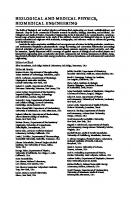
Calcium Alkoxide Masuda et al. (1990) studied nanohydroxyapatite powder production using the alkoxide-based system containing calcium diethoxide, triethyl phosphite, ethanediol, and ethanol, modiied with water and acetic acid. Within this system, they synthesized powders and found that the determining factor for the composition of the resultant powder was the solution’s pH. This was the irst systematic approach on controlling the chemistry for pure nanohydroxyapatite production. No attempts were made to produce monolithic materials or coatings. Based on the basic chemistry of Matsuda et al. (1990), Ben-Nissan et al. (Ben-Nissan and Chai 1995; Chai et al. 1998; Gross et al. 1998; Ben-Nissan et al. 2001), and Green et al. (2001) employed a modiied alkoxide process to synthesize HAp powders and coatings via the sol–gel technique. In a further modiied technique, Milev et al. (Milev et al. 2002, 2003; BenNissan et al. 2001) used multinuclear NMR spectroscopy to monitor the synthesis of carbonate-containing HAp for powder, nanoplatelets and nanocoating productions (Figure 2.9). Layrolle and Lebugle (1994) developed a synthesis route of different calcium phosphates, using anhydrous ethanol as solvent and calcium diethoxide (Ca(OEt)2) and orthophosphoric acid (H3PO4) as reagents. In a systematic approach using a simple variance of the ratio of reagents, calcium phosphates of various chemical compositions Ca x(HPO4)y(PO4)z were precipitated in the ethanol. The solids that formed were characterized by different physicochemical and thermal analyses. The results revealed that the different solid calcium phosphates are amorphous and of the nanoscale and have large speciic surface areas and high reactivities. Layrolle et al. (1998) also described the production of a nanosized, amorphous, and carbonate-containing calcium phosphate powder synthesized from calcium diethoxide and phosphoric acid in ethanol via a sol–gel method. They concluded that after sintering, the decomposition of carbonated HAp generated a microporous ceramic with an average pore size of 0.2 μm and an open porosity of 15.5% and that this microporous bioceramic can be used as bone iller. Roest et al. (Roest et al. 2001, 2004; Roest 2010) developed carbonate nanohydroxyapatite coatings on anodized titanium and titanium alloy (Ti–6Al–4V) by dip and spin coating methods successfully. Similar methods were used to coat a range of substrates with zirconia nanocoatings. Zreiqat et al. (2005) compared the effect of surface chemistry modiication of titanium alloy (Ti–6Al–4V) with zinc, magnesium, and alkoxide-derived hydroxy carbonate apatite (a)
(b)
(Å) 1967 984 0 4
4 3 3
2 (µm)
1
1 0
2 (µm)
0
FIGURE 2.9 (a) SEM of nanohydroxyapatite coating (scale 100 nm), (b) AFM image of the same nanohydroxyapatite coating.
© 2011 by Taylor & Francis Group, LLC
56
Biological and Biomedical Coatings Handbook: Processing and Characterization
produced by Roest et al. 2001, on the regulation of key intracellular signaling proteins in human bone-derived stem cells (HBDC) cultured on these modiied Ti–6Al–4V surfaces. They concluded that the surface modiication with carbonate apatite coated or Mg incorporated apatite may contribute to successful osteoblast function and differentiation at the skeletal tissue-device interface. Calcium Acetate Aqueous sol–gel chemistry routes based on ammonium hydrogen phosphate as the phosphorus precursor and calcium acetate monohydrate as the source of calcium ions have been developed by Bogdanoviciene et al. (2006) to prepare hydroxyapatite powder samples with different morphological properties. In the sol–gel processes, an aqueous solution of ethylenediaminetetraacetic acid (EDTA) or tartaric acid (TA) as complexing agents was added to the reaction mixture. It was reported that the monophasic Ca10(PO4)6(OH)2 samples were obtained by calcination of precursor gels for 5 h at 1000°C. They demonstrated that the proposed aqueous sol–gel methods are very simple, inexpensive, and thus appropriate for the large-scale fabrication of calcium hydroxyapatite powders and ceramics. Cihlar and Castkova (1998) examined the synthesis of calcium phosphates from methyl-, ethyl, i-propyl, and n-butyl phosphates and calcium acetate in acidic and basic water– alcoholic solutions. A mixture of HAp and beta-tricalcium phosphate (β-TCP) was achieved through the reaction of all alkylphosphates with calcium acetate in an acidic solution. Calcium pyrophosphate was achieved when the reaction proceeded in the presence of ammonium hydroxide. HAp with an admixture of calcium pyrophosphate or β-TCP was prepared by means of monoethanolamine or diethanolamine catalysts. Calcium Chloride Andersson et al. (2005) developed a degradable, hierarchically porous apatite composite material from a simple low-temperature synthesis. HAp was produced through a sol–gel method at near room temperature conditions. They used CaCl2·2H2O, Na2HPO4·2H2O, cetyltrimethylammonium bromide (C16TAB), ammonia solution, and tetraethoxysilane (TEOS) as starting material for this investigation. Two stock solutions were prepared from Na2HPO4·2H2O and CaCl2·2H2O, using distilled and deionized water. C16TAB was dissolved in phosphate-containing stock solution, after which ammonia was added. The mixture was kept under constant stirring in a closed beaker. Gel formation was induced upon addition of the calcium chloride stock solution to the mixture. The resulting gel was reported to consist of HAp and sodium calcium phosphate. The hybrid material was shown to eficiently induce calcium phosphate formation under in vitro conditions and simultaneously work as a carrier system for drugs. Sarig and Kahana (2002) synthesized nanocrystalline plate-shaped particles of HAp directly precipitated from dilute calcium chloride and sodium phosphate solutions. The direct precipitation of hydroxyapatite was achieved by submitting the aqueous solutions of calcium and phosphate to microwave irradiation immediately after mixing. Calcium Hydroxide Sol–gel inorganic–organic hybrid material coated on glassy carbon electrode used for the immobilization and study of double-stranded DNA with redox-active molecules was developed by Wang et al. (2005). They produced a hybrid material coating consisting of © 2011 by Taylor & Francis Group, LLC
Synthesis and Characterization of Hydroxyapatite Nanocoatings by Sol–Gel Method
57
nanohydroxyapatite (HAp)–polyvinyl alcohol (PVA). The hybrid was prepared from phosphoric acid solution and saturated calcium hydroxide solution, while the PVA was dissolved in distilled water. They discovered that mixing a suitable quantity of PVA in HAp sol can prevent the HAp coating from cracking and enhance its stability. The properties of the nano-HAp-PVA hybrid were affected by the concentration of PVA. HAp and tricalcium phosphate (TCP) powders and coatings were synthesized by Tkalcec et al. (2001) via the sol–gel technique to examine the formation mechanism of crystalline phases in the iring processes of coatings with different Ca/P molar ratios. Calcium hydroxide was suspended in ethanol and ethylhexanoic acid (EHA) was added dropwise to this suspension. The solution was then iltered by pressure iltering to obtain a clear solution of calcium 2-ethylhexanoate (Ca(O2C8H15)2). Calcium 2-ethylhexanoate and 2-ethyl-hexyl-phosphate were used as calcium and phosphorus precursors, respectively. Coatings were deposited on Si–wafer and Ti–alloy substrates by dipping the substrates into sols at room temperature. The results from the work showed that dip-coating and sintering in two cycles yielded a homogeneous and dense coated ilm with a thickness of 250 nm. Calcium Nitrate Calcium nitrate (Ca(NO3)2) has been a popular calcium precursor for the synthesis of hydroxyapatite. The citric acid sol–gel combustion method has been employed by Han et al. (2004) for the synthesis of nanocrystalline HAp powders from calcium nitrate, diammonium hydrogen phosphate, and citric acid. HAp powder was used to sinter a monolithic ceramic product in order to illustrate its sinterability, open porosity, lexural strength, and structural rigidity. Microscopy revealed that there were many pores in the micropore sizes ranging between 1 and 5 μm of irregular shape. Although the open porosity of the resulting ceramic was about 19%, the pore size is not good for bone ingrowth. After sintering at 1200°C, the grain size is about 3 μm. Weng et al. (2002) also examined the effect on the addition of citric acid on the formation of sol–gel derived HAp. In order to improve the gelation in the sol–gel preparation of HAp by using Ca(NO3)2 and PO(OH)3−x(OEt)x as precursors, citric acid was selected as an enhancing gelation additive. HAp derived from the mixed precursor solutions with citric acid showed a different reaction path from that without citric acid. They suggest that citric acid plays a role in enhancing gelation through the strong coordination ability of Ca ions with citrate groups. They have also concluded that the addition of citric acid can provide a way to synthesize a pure oxy-HAp or an apatite with carbonated HAp, HAp, and minor β-TCP, which might have good bioactivity. Balamurugan et al. (2006) developed a different sol–gel technique for the synthesis phase of pure HAp powder. Triethyl phosphite and calcium nitrate were used as phosphorus and calcium precursors. The powders obtained were dried and calcined at different temperatures up to 900°C. X-ray diffraction analysis and Raman spectra were reported to show the presence of pure HAp. Kim et al. (2005) coated hydroxyapatite composites with titania (TiO2) on titanium (Ti) substrate by a sol–gel route, and the mechanical and biological properties of the coating systems were examined. Calcium nitrate tetrahydrate (Ca(NO3)2·4H2O) and triethyl phosphite (P(OC2H5)3) were hydrolyzed together with ethanol and distilled water. Ammonium hydroxide (NH4OH) was added stepwise to the mixture. To produce a TiO2 sol, titanium propoxide (Ti(OCH2CH2CH3)4) was hydrolyzed within an ethanol-based solution © 2011 by Taylor & Francis Group, LLC
58
Biological and Biomedical Coatings Handbook: Processing and Characterization
containing diethanolamine ((HOCH2CH2)2NH) and distilled water. The prepared HAp and TiO2 sols were mixed together and stirred vigorously to obtain HAp–TiO2 composite sols. Coatings were produced under a controlled spinning and heat treatment process. The HAp–TiO2 composite coating layers were homogeneous and highly dense, with a thickness of about 800 to 900 nm. The adhesion strength of the coating layers with regard to the Ti substrate increased with increasing TiO2 addition. The osteoblast-like cells were tried and reported that they grew and spread actively on all the composite coatings. They concluded that the sol–gel derived HAp–TiO2 composite coatings possess excellent properties for hard tissue applications. HAp coatings on titanium and its alloy were synthesized by Stoch et al. (2005) for facilitating and shortening the processes towards osseointegration. HAp coatings were obtained by the sol–gel method with sol solutions prepared from calcium nitrate tetrahydrate and triammonium phosphate trihydrate as the calcium and phosphorous sources. Two types of gelatin were added to the sol: agar–agar or animal gelatine. Both were found to enhance the formation and stability of amorphous HAp using soluble salts as the sources of calcium and phosphate. The biological activity of phosphate coatings was observed in the SBF. They found that the chemical composition and structure of HAp coatings depends on the pH and inal thermal treatment of the layer. Sol–gel synthesis and template preparation of nanomaterials to yield a new general route for fabricating highly ordered HAp nanowire arrays were fabricated by Yang et al. (2005) using a porous anodic aluminum oxide (AAO) template from a sol–gel solution containing P2O5 and Ca(NO3)2. The AAO template membrane was immersed into this sol for the desired amount of time and allowed to dry in air. Excess sol on the membrane surface was carefully wiped off and then heat-treated in an open furnace. HAp nanowire arrays were formed inside the pores of the AAO template. Various characterization techniques such as TEM, SEM, XRD, and XPS were applied to examine the structure of HAp nanowires. HAp nanowires had a uniform length and diameter and form highly ordered arrays, which are determined by the pore diameter and the thickness of the applied AAO template. They have reported that their novel method of preparing highly ordered HAp nanowires with a large area might be very important in many biomedical applications. No attempts were made to use the wires as nanocomposite coatings. Thin sol–gel formed calcium phosphate (Ca–P) ilms were produced on sintered poroussurfaced implants as an approach to increase the rate of bone ingrowth by Gan and Pilliar (2004). Porous-surfaced dental implants (endopores implants) were used for the sol–gel coating of sintered porous surface structures. The porous surface was created by sintering Ti–6Al–4V microspheres of 45 to 150 μm in diameter onto a machined Ti–6Al–4V substrate. The ilms were prepared using both an inorganic precursor solution (with calcium nitrate tetrahydrate and ammonium dihydrogen phosphate) and an organic precursor solution (with calcium nitrate tetrahydrate and triethyl phosphite). They reported that both approaches resulted in the formation of nanocrystalline carbonated HAp ilms but with different Ca/P ratios and structures. They commented that while both the inorganic and organic methods resulted in ilms with nanocrystalline or submicron crystalline carbonated HAp ilms, the inorganic method resulted in ilms that differed signiicantly in structure, displayed a more irregular surface texture, and were less dense. Cross-sectional TEM studies revealed an interfacial reaction product phase when using the inorganic method, and calcium titanium oxide was developed. In order to improve thermal stability and strength of hydroxyapatite powder during thermal or plasma spraying, luorine is added to hydroxyapatite to form HAp/luoroapatite (FA) solid solution. © 2011 by Taylor & Francis Group, LLC
Synthesis and Characterization of Hydroxyapatite Nanocoatings by Sol–Gel Method
59
In 2001, Cheng et al. (2001) developed a sol–gel method to synthesize a (HAp)/(FA) solid solution. Calcium nitrate–4 hydrate, phosphoric pentoxide, and triluoroacetic acid (TFA) were used as the precursors. Triethanolamine (TEA) was used as a promoter for incorporating luorine into Ca phosphates. Mixed ethanol solutions of the Ca and P precursors in Ca/P ratio of 1.67 with different amounts of TFA and TEA were prepared; the mixed solutions were dried on a hot plate to convert them to the as-prepared powders. HAp/ FA solid solutions were obtained after the powders were calcined at temperatures up to 900°C. Cheng et al. (2004) utilized a sol–gel method to synthesize a luoridated hydroxyapatite (FHAp) phase. Calcium nitrate tetrahydrate, phosphoric pentoxide, and ammonium hexaluorophosphate were used as precursors. The Ca, P, and F precursors were mixed under designated proportions to form solutions with a Ca/P ratio of 1.67. In order to obtain an FHA phase with various luorine contents, different amounts of ammonium hexaluorophosphate were added in the Ca–P mixed solutions. The synthesis of HAp nanopowders using a sol–gel route with calcium nitrate and ammonium hydrogen phosphate as calcium and phosphorous precursors, respectively, were described by Bose and Saha (2003). Sucrose was used as the template material, and alumina was added as a dopant to study its effects on particle size and surface area. The average particle size of porous HAp samples was between 30 and 50 nm. Hsieh et al. (2002) successfully developed a simple rapid-heating method for calcium phosphate coatings on Ti–6Al–4V substrates deposited by using a sol–gel derived precursor. The preparation of the precursor was carried out by mixing Ca(NO3)2·4H2O and (C2H5O)3PO in 2-methoxy ethanol. Upon aging, the as-prepared solution was closely capped and placed in an oil bath for 16 h. Upon gelation (drying), the solvent was evaporated in the same oil bath so that a viscous precursor was obtained. Adhesive strength tests were conducted and the results indicated that, at the irst coating layer using either spin or dip coating, the breakages occur at the glue-coating interface, representing an adhesive strength higher than 90 MPa. Thus, the irst layer is irmly adhered to the substrate. Hsieh et al. also found that a porous structure, with a pore size of 10 to 20 μm, was formed on the outermost coating surface. It was reported that this structure is due to the fast decomposition during rapid heating of the precursor deposited on the substrate, and is very suitable for ingrowth of living cells. Although this comment is true for cell penetration it does not allow vascularization, which requires pore sizes of 140 to 500 μm. Lim et al. (2001) investigated the bioactivities of the coating by analyzing the variation of ion concentrations of Ca and P in simulated body luid after soaking, using an inductively coupled plasma–atomic emission spectrometer. Ti/HAp coating solutions with variable HAp concentrations were derived from calcium nitrate (Ca(NO3)2·4H2O) and phosphoric acid (H3PO4) that were dissolved in ethylene glycol monomethyl ether (CH3OCH2CH2OH). Coating surfaces, after soaking in simulated body luid, indicated signiicant morphological changes when investigated by ield emission-scanning electron microscopy. Dicalcium Phosphate Dihydrate The crystal growth and morphology of the nanosized HAp powders synthesized from dicalcium phosphate dihydrate (CaHPO4·2H2O) and CaCO3 have been investigated by Shin et al. (2004). The nanosized HAp powders were obtained from the hydrolysis of dicalcium phosphate dihydrate and CaCO3 with NaOH. They discovered that the only product synthesized from dicalcium phosphate dihydrate was HAp, and the crystallinity of the HAp was improved with increasing annealing temperature. The crystallite size of the HAp © 2011 by Taylor & Francis Group, LLC
60
Biological and Biomedical Coatings Handbook: Processing and Characterization
samples with Ca/P equal to 1.0 was about 50 nm thick and 100 nm long. As the Ca/P ratio increased by adding CaCO3, the particle size increased to 200 nm thick and 500 nm long.
Sol–Gel Hydroxyapatite-Nanocoated Coralline Apatite Coral mineral has had considerable success as a bone graft material in view of its interconnected porous structure, which ranges from 150 to 500 μm (Figure 2.10). In morphology, it is similar to the human cancellous bone and is one of a limited number of materials that will form chemical bonds with bone and soft tissue in vivo. On the other hand, unless it is modiied by chemical means, coral as calcium carbonate is unsuitable for bone graft applications due to its high dissolution rate. Conversion to hydroxyapatite and the use of nanocoatings improves a range of properties. Nanocoated coralline hydroxyapatite has been reported to have enhanced bioactivity and strength (Hu et al. 2001; Ben-Nissan et al. 2004). Natural Skeletons Using natural skeletons in a direct way as a scaffold for growing cells into tissue emerged for making new bone tissue as a product of hydrothermal processing (Weber et al. 1974; Roy et al. 1974). Transformed coral has been the primary source of natural skeletons for bone tissue engineering because of its chemical, crystallographic, and structural similarity to human bone. Since then researchers have attempted to make use of the skeletons of hydrozoans, cuttleish (Rocha et al. 2005), marine sponges (Green et al. 2003), nacre seashell, and echinoderm spines (Martina et al. 2005; Roy et al. 1974) as templates with optimal ranges of pore sizes, channels, and structural networks for organizing and nourishing the growth of human tissues as a prelude to transplantation into the patient. In a number of studies, various candidate biomatrices were identiied in nature with varied chemical homologies and structural analogies to human extracellular matrices and whole tissues (Green 2003; Green and Ben-Nissan 2008). They include nacre marine shell,
Acc.V Spot Magn 30.0 kV 3.0 80x
FIGURE 2.10 Natural coral containing interconnected pores.
© 2011 by Taylor & Francis Group, LLC
Det WD GSE 11.5 Wet
200 µm 0.9 Torr
Synthesis and Characterization of Hydroxyapatite Nanocoatings by Sol–Gel Method
61
marine sponge skeletons, echinoderm skeletal elements, and coral skeletons. The utility of selected species of these marine animals has been applied to the regeneration of human bone and cartilage. However, their full utility in these tissues and other tissues has yet to be harnessed and exploited. Coral and Coralline Apatite Natural coral exoskeletons have been used widely as a bone replacement in orthopedic, craniofacial, dental, and neurosurgery owing to their combination of good mechanical properties, open porosity, and ability to form chemical bonds with bone and soft tissues in vivo (Ben-Nissan 2004). In fact corals have the best mechanical properties of the porous calcium-based ceramics and resorb at a rate equivalent to host bone formation. The abundance, conformation, and composition of the organic matrices are responsible for successful biological integration of coral with human host (Dauphin 2003). Use of coral skeletons for general routine orthopedic surgery and tissue engineering has so far been limited to external ixation devices as they are inappropriate for strictly load-bearing applications. Sol–gel coating technologies can be used to enhance the strength of corals and this enables them to be used at more skeletal locations. Corals offer great opportunities to tissue engineering of bone either in their natural form or as hybridized synthetic forms (Petite et al. 2000). Coral skeleton combined with in vitro expanded human bone marrow stromal cells (HBMSC) increased osteogenesis more than that obtained with scaffold alone or scaffold with fresh marrow. In vivo large animal segmental defect studies led to complete recorticalization and formation of a medullary canal with mature lamellar cortical bone giving rise to clinical union in a high number of cases (Petite et al. 2000). Structural and biomineralization studies of coral can be used as a guide for the development of new advanced functional materials because of the unique nanoscale organization of organic tissue and mineral as highlighted by Ehrlich et al. (2006). At a macrostructural level, the deep-sea bamboo coral exhibited bonelike biochemical and mechanical properties. A specialized collagen matrix (acidic ibrillar) serves as a model for future potential tissue engineering applications. The matrix supported both osteoblast and osteoclast growth and the exceptional bioelastomeric properties of the collagen matrix (gorgonin) of this coral make it potentially suitable for blood vessel implants. Quinones cross-link and harden the collagenous gorgonin proteins and closely resemble human keratin. The mechanism by which gorgonin is synthesized and interacts with the process of mineralization may provide lessons for the generation of a synthetic collagen-like material (Ehrlich et al. 2006). Nanocoated Coralline Apatite Current commercially available bone graft materials using hydrothermal conversion only achieve partial conversion of coralline calcium carbonate to HAp. Unfortunately, being limited to the outer surface, the inner core remains as unconverted calcium carbonate of the original coral (Shors 1999). This material has the advantage of retaining a favorable pore size and bioactivity, with improved properties, compared to native coral. Unfortunately, this also generates an unknown factor of biodegradation due to the differing solubility rates of hydroxyapatite and unconverted calcium carbonate. As a result, this material is subject to fast dissolution in the physiologic environment, compromising strength, durability, tissue integration, and ultimately the longevity. It was discovered (Hu et al. 2001; Ben-Nissan et al. 2004) that the application of a hydroxyapatite sol–gel coating onto the monophasic HAp derived from the hydrothermally © 2011 by Taylor & Francis Group, LLC
62
Biological and Biomedical Coatings Handbook: Processing and Characterization
converted coral increased its mechanical properties. This nanocoating was reported to increase all of the mechanical properties. Coral, in addition to the macropores, also contains meso- and nanopores ranging between 5 and 50 nm within a ibrous structure that constitutes the interpore area between the large macropores. The method involves a unique patented two-step conversion procedure. In the irst stage, corals possessing a suitable macropore structure are converted to pure HAp, with complete replacement of calcium carbonate by phosphatic material throughout the specimen. The HAp can be prepared from coral by a hydrothermal reactor. The reaction can be carried out at 250°C with an ammonium monohydrogen phosphate solution for a predetermined period of time. Additional stage involves the use of sol–gel derived HAp with the converted coralline apatite. In general, the alkoxide method used involves the formulation of a homogeneous solution containing all of the component metals in the correct stoichiometry. Mixtures of metal alkoxides and/or metal alkanoates in organic solvents that have been stabilized against precipitation by chemical additives (amines, glycols, acetylacetone, etc.) have proven the most successful. All synthetic procedures for the preparation of sols were carried out in a dry nitrogen atmosphere due to the hygroscopic nature of the starting alkoxide precursors. The calcium alkoxide precursor solution was prepared by dispersing calcium diethoxide (Ca(OEt)2) in absolute ethanol (Et(OH)). Phosphorous precursor solution was then prepared by diluting triethyl phosphite (P(OEt)3) in absolute Et(OH) (Ben-Nissan et al. 2001). After complete dissolution of the calcium diethoxide, the phosphorous precursor solution can be added to the calcium precursor solution. The clear solutions were aged at ambient temperature before being used. Coatings were formed using these solutions followed by subsequent heat treatment for further densiication. Detailed analyses using SEM revealed that the coating step effectively obliterates the surface meso- and nanopore systems while leaving the macropore system intact (Figure 2.11). Application of nanocoating had two major effects; irst, the improvement of the mechanical properties compared to traditional coral materials, and second, it enhanced the bioactivity of the material. Mechanical testing indicated that all properties have increased including compression, biaxial, lexural strengths, and the elastic modulus (Ben-Nissan
300 nm
Mag = 40.34 K X
EHT = 1.00 kV Noise Reduction = Line Int. Diagonal A = SE2
Date: 4 Aug 2003
WD = 6 mm
Extractor I = 220.40 µA
Time: 14:15:59
Gun Vacuum = 7.51e-0.10 mBar
FIGURE 2.11 SEM reveals that the coating step effectively obliterates the surface meso- and nanopore systems, whilst leaving the macropore system intact.
© 2011 by Taylor & Francis Group, LLC
Synthesis and Characterization of Hydroxyapatite Nanocoatings by Sol–Gel Method
63
et al. 2004). It is anticipated that this new patented process and material can be applied to bone graft applications where high strength requirements and longevity are pertinent.
Mechanical Properties of Thin Films Understanding of the long-term mechanical reliability of biomedical thin ilms is pertinent in clinical applications. Hence, a number of methods capable of quantitatively measuring the mechanical properties are required. Since the 1980s there have been constant improvements and developments in equipment capable of extracting the structure and properties of thin ilms and also the adhesion of the coating to an underlying substrate (Ben-Nissan and Pezzotti 2002). A general review of thin ilm mechanical properties of coatings is given by Nix (2006). According to his work on both thin and thick ilm coatings, the main factors that can inluence mechanical reliability are many; however, the most important ones are the interfacial properties, residual stresses for thick coatings, substrate, and thin ilm thickness and its geometry. The evaluation of stress in a nanocoating due to deposition technique and heat treatments applied plays an important role in regards to mechanical stability. The potential for cracking and spalling of the coating due to inbuilt stresses (whether they are tensile or compressive) or from external mechanical loading plays a key part in the successful use of biomaterial implants. The stress in a ilm is a combination of the following components and is described in Equation 2.4: intrinsic (deposition, mode of growth, structure), thermal expansion mismatch between ilm and substrate (speciically in thick ilms) due to changes in temperature and externally applied stresses (Lepienski et al. 2004): σf = σ(intrinsic) + σ(thermal) + σ(external)
(2.4)
Stress measurement by substrate curvature is a simple method requiring either (1) a stylus proilometer capable of scans 10 mm in length or more, or (2) using a phase shifting interferometer. The advantages of using an optical method such as interferometry are high accuracy of about 6 nm, substrates with curvature of up to 3 µm are acceptable, and it is a rapid and straightforward technique to use. In stylus proiometry, the substrate needs to be suficiently thin for adequate measurement of the curvature. The method requires careful and precise placement of the sample, so that a cross scan in the x and y directions can be made on the surface (preferably both sides) before and after coating. The stress in the coating (intrinsic + thermal) can be evaluated using the Stoney formula without prior knowledge of the coating properties. The information that is required is coating thickness, substrate thickness, and its Young’s modulus. Stoney’s equation (Stoney 1909) shows the relationship between the change in the radius of a coated and uncoated substrate and the corresponding stress in the layer (Equation 2.5):
σ=
© 2011 by Taylor & Francis Group, LLC
Es ts2 1 1 1 − 6 Rf Ri (1 − ν s ) tf
(2.5)
Biological and Biomedical Coatings Handbook: Processing and Characterization
64
where Ri is the radius of curvature before coating, Rf after coating, Es and vs the modulus and Poisson’s ratio of the substrate, ts the substrate thickness, and tf the ilm thickness. Assuming that the scan length L of the substrate is much greater than the inal bow B of the substrate, the radius R can be calculated using Equation 2.6. R=
L2 8B
(2.6)
Compressive stress in the ilm leads to a convex delection, whereas tensile stress results in concave delection. Measurements can be made in situ during deposition or thermal treatment with optical means by interferometry or delection method (cantilever beam) using a low-power laser. Similarly, elastic strain in ilms can be measured by x-ray diffraction from the change in crystal lattice d-spacing, from which the stress can be determined given knowledge of Young’s modulus and strain-free lattice spacing (which may be unknown in many cases) (Tsui et al. 1998). The most commonly used methods for characterizing the performance of micro- and nanocoatings on substrates can generally be divided into the measurement of coating properties and adhesion strength. There are a number of excellent methods that can be used in thin ilm mechanical properties evaluation, and some of the commonly used methods are nanoindentation, tensile testing, scratch testing, adhesion and wear testing, pin-on-disk testing, pull-out test, and bending and bulge testing. Some of these are shown in Figure 2.12a, b, c, and d. (a)
(b) Pmax
Force sensor
Load, P
Acoustic sensor
dP dh
Holder Diamond tip
Sample Displacement, h (c)
(d) P/2
substrate
P/2
crack
h
coating
FIGURE 2.12 Some of the thin ilm testing methods: (a) typical scratch testing device (based on the Quad Group Inc. Romulus III universal test equipment), (b) schematic of a nanoindentation load vs. displacement load and unloading curve from an indentation experiment, (c) schematic of the four-point bend delamination method, and (d) Orthopod® pin on disk wear tester.
© 2011 by Taylor & Francis Group, LLC
Synthesis and Characterization of Hydroxyapatite Nanocoatings by Sol–Gel Method
65
Adhesion testing is essential to ensure the coating will adhere properly to the substrate to which it is applied. Many techniques have been used for adhesion measurement of ilms and coatings as demonstrated by Mittal (1995). The most popular test methods for measuring the bond strength of ilm on substrate systems include pull-off, cross-cut, indentation scratching at increasing loads, and pin-on-disk. Microtensile testing is also an excellent method to determine the adhesion integrity of nanocoatings. Pull-off testing is perhaps the most common method for determining the bond strength between a thin ilm and a thick substrate. Many types of conigurations have been proposed (Vallin et al. 2005) using universal testing machines or dedicated tensile testers. The main requirements are that the alignment of grips and sample ixture is precise to ensure uniform loading and that the adhesive used to bond the sample to the ixture is suficiently strong (stronger than the bond strength of the ilm–substrate) and does not penetrate the interface of interest. The bond strength is determined from the critical load required to separate the ilm–substrate contact area. The main advantage of pull-off testing is its applicability and versatility to a wide range of coating/substrate systems. It can be used for both soft lexible coating as well as hard brittle ones. The weakness in typical pull testing is the wide variation in data. One must perform multiple tests on a given sample and statistical analysis to obtain reliable quantitative data. In biomaterials, pull-out is a more common mode of failure of a bone implant than bone fracture. Pull-out may not necessarily occur at the interface between bone and coating, but instead between the metal and the hydroxyapatite coating. Pin-on-disk tribometers are used to determine the wear resistance and friction coeficient of surfaces. The tester consists of a pin (normally a ruby, tungsten carbide, or metal sphere) under a static load in contact with a rotating sample. Wear coeficients for the pin and disk material are calculated from the volume of material lost during the test. The method facilitates the study of friction and wear behavior of many material combinations with or without lubricant. Pin-on-disk test can be run for an extended period of time either in air or a simulated body environment to provide information on the degradation of the coating with time (sliding distance). Similar devices that are used in biomaterials research are pin-on-plate type wear testing machines, such as the Ortho-Pod instrument (Advanced Mechanical Testing, Inc., Watertown, MA) (Figure 2.12d). This has six stations for the pins with independent servocontrolled variables that correspond to rotary motion of both the plate and the pins and the normal load applied to each of the six pins. The pin rotation feature gives this machine the ability to generate pin/plate sliding motions that are typically not available on standard pin-on-disk machines. The Ortho-pod is an excellent tool for testing implant materials whose wear characteristics depend upon various sliding directions (crossings) as well as load, in either dry or a fully lubricated environment (serum or other luids). Scratch testers (Figure 2.12a) use a small diamond stylus or hard metal (such as tungsten carbide) normally with a 200-µm radius that is drawn across the coated surface at a constant velocity at increasing load. The load on the diamond causes stresses to be increased at the interface between the coating and the substrate, which can result in laking or chipping of the coating. The load at which the coating irst delaminates is called the critical load and is a measure of coating adhesion. Coating failure can be determined from load and the distance at which delamination begins using microscopy, or from the change in friction or using an acoustic emission sensor. In addition to the critical load, the applied normal force, the tangential (friction) force, and the penetration depth are obtained. Examining scratch test results is dificult due to the complex stress states involved and the broad array of damage processes that can occur depending on ilm thickness and the © 2011 by Taylor & Francis Group, LLC
66
Biological and Biomedical Coatings Handbook: Processing and Characterization
mechanical properties of the ilm and substrate. The test is sensitive to loading rate, stylus shape, environment (humidity), and scratch speed. Thus, it is dificult to relate the critical load to ilm adhesion. Three- and four-point bending methods have been used to ascertain the interfacial fracture resistance between dissimilar materials and ilms on substrates and to provide quantitative measures of the interfacial fracture energy. The thicknesses of these substrates are usually much smaller than their lateral dimensions, so that simple beam bending mechanics can be applied to describe their elastic response (Saha and Nix 2002). A fracture-mechanics-based method for four-point bending developed by Charalambides et al. (1989) for interfaces between dissimilar materials has been applied in many areas including biomaterials research (Angelelis et al. 1998; Kuper et al. 1997; Dauskardt et al. 1998; Hoinger et al. 1998; Suansuwan and Swain 2003) to measure interface fracture energy. The method requires a bend bar of the coated substrate with a notch machined in the coated layer (Figure 2.12c). As the bending moment increases, a crack initiates from the notch and propagates to the interface. For a suficiently weak interface bond, the cracks delect and propagate along the interface. The interfacial fracture energy is given by Equation 2.7:
γ =
(
21Pc2l 2 1 − ν s2 2 3
16Esb h
)
(2.7)
where b is the specimen or beam width, h is the total thickness, l is the moment arm (distance between inner and outer loading lines), Pc is the critical load for stable crack propagation, and vs and Es are Poisson’s ratio and Young’s modulus of the substrate, respectively. This method has the advantage that the interface fracture energy is independent of the crack length as long as the crack tip is not too close to the precrack or the loading points. In bulge and blister testing, the ilm–substrate system is pressurized with a luid or gas through a hole in the substrate. The height of the resulting hemispherical bulge in the ilm is then measured by optical microscopy or an interferometer. The pressure and delection height can be used to provide in-plane information on elastic, plastic, and time-dependent deformation. In blister testing the pressure is increased until the ilm starts to debond from the substrate. The interfacial energy can be determined from the critical pressure for debonding as shown in Equation 2.8 (Bennet et al. 1974):
γ =
(
)
p 2 3 − ν f2 r 4 3 f f
16E t
(2.8)
where p is the applied pressure, r is the radius of the hole, Ef is Young’s modulus of the ilm, vf is Poisson’s ratio of the ilm, and tf is the ilm thickness. Two of these commonly used methods, namely, microtensile testing and nanoindentation, are discussed in more detail below given their relevance in biomaterial property evaluations and based on studies by the main author’s research group. Microtensile Testing The method is suitable for determining properties of both thin and thick coatings on a variety of ductile substrates and provides insights into interfacial delamination susceptibility © 2011 by Taylor & Francis Group, LLC
Synthesis and Characterization of Hydroxyapatite Nanocoatings by Sol–Gel Method
67
by the application of controlled external stresses (Filiaggi et al. 1996; Wang et al. 1998; Roest et al. 2004; Latella et al. 2007a, 2007b). In this adhesion test, the coating is deposited on a tensile coupon, which can then be pulled in a universal testing machine or a specialized device that can be placed under the objective lens of an optical microscope or in a scanning electron microscope. Figure 2.13a shows a schematic of a tensile sample with a thin coating layer that can be uniaxially loaded at deined rates. The cracking, damage evolution, and failure in the coating can be viewed in situ or ex situ after application of speciic strains. Brittle coatings on ductile substrates when uniaxially stressed produce parallel cracks in the coating layer perpendicular to the tensile axis and normal to the interface as demonstrated in Figure 2.13b for a sol–gel silica ilm on stainless steel strained to about 15%. These cracks generally extend through the thickness of the coating and along the width of the sample and increase in number with additional elongation, leading to a decrease in the crack spacing. For some systems, cracks may also be accompanied by localized delamination of the coating from the substrate. Eventually, delamination of the coating signals the end of the lifetime of the coated system. For softer and more compliant ilms, cracking can be irregular and ilm debonding reduced substantially. The drawback with these semibrittle ilms is that quantitative analysis becomes more dificult. Tensile testing is advantageous in that the stress ield is uniform along the gauge length of the sample and relatively small specimens can be used. Similarly, using optical or scanning electron microscopy to view the damage in situ during loading offers useful insights into material failure mechanisms (Ignat et al. 1999; Latella et al. 2004). The only prerequisite for this type of test is that for analysis of the coating behavior, the residual stress, and Young’s modulus of the coating are required by other means, such as from substrate curvature measurements and nanoindentation, respectively. Microtensile tests provide insights into delamination and fracture processes and for ranking the practical adhesion performance of different coatings. The ilm debonding behavior is essential to the reliability of ilm–substrate systems, particularly where mechanical loading and chemical interactions are encountered. For ilms that crack and debond in a controlled fashion, one can use linear elastic fracture mechanics relations to
(a)
(b)
6 um FIGURE 2.13 (a) Shows a schematic of the tensile test specimen, (b) parallel cracks and damage in a sol–gel silica coating on stainless steel strained to about 15% (tensile axis is in the horizontal direction). Small debonded ilm region between cracks can be seen in the center of the image.
© 2011 by Taylor & Francis Group, LLC
68
Biological and Biomedical Coatings Handbook: Processing and Characterization
extract intrinsic ilm properties (strength and fracture toughness) and interfacial adhesion characteristics (Ignat 1996; Harry et al. 1998; Scaidi and Ignat 1998). On tensile straining, the coating-substrate sample is examined to determine the instant of irst cracking in the coating, which corresponds to a strain εc. Using Young’s modulus of the ilm (Ef) the critical stress, σc, for cracking may be calculated as follows: σc = εcEf + σr
(2.9)
where σr is the residual stress of the coating. The fracture energy of the coating is obtained from the following equation (Hu and Evans 1989): γf =
σ c2 h
Ef
π g(α ) +
σc 3τ
(2.10)
where γf is the fracture energy (J m−2), h is the thickness of the coating, and α is Dundar’s parameter α = (Ef − Es)/(Ef + Es), where Es is Young’s modulus of the substrate. The g(α) is obtained from Beuth and Klingbeil (1996) and τ = σ y / 3 , where σy is the yield stress of the substrate. The toughness of the ilm is then given by K IC = γ f Ef
(2.11)
Adhesion of the ilm to the substrate is determined by the measurement of the interfacial fracture energy. During tensile straining, the instant of irst debonding of the ilm corresponds to a strain εd. The interfacial fracture energy is calculated as follows: γi =
1 Ef hε d2 2
(2.12)
Nanoindentation The methodology and instrumentation have been developed markedly since the early 1990s and it is now considered a routine and relatively effective means of obtaining accurate measures of Young’s modulus and hardness of coatings. It is the method of choice by many practitioners in the biomaterials ield for measuring the mechanical properties of nanocoatings and implants due to the simplicity of operation. The main requirements for obtaining the best possible results with such testing rely on adequate sample preparation, calibration of equipment, and corrections for thermal drift, initial penetration, frame compliance, and indenter tip shape (Oliver and Pharr 1992; Field and Swain 1993; Swain and Mencik 1994; Field and Swain 1995; Mencik and Swain 1995; Gan et al. 1996; Mencik et al. 1997; Fischer-Cripps 2002). In the well-known conventional microindentation testing, a load is applied through a diamond tip of known geometry (typically Rockwell, Vickers, or Knoop) into the material surface and then removed and the area of the residual impression is measured by optical means to give the material hardness, an example of which is shown by Kealley et al. (2008) © 2011 by Taylor & Francis Group, LLC
Synthesis and Characterization of Hydroxyapatite Nanocoatings by Sol–Gel Method
69
for HAp ceramics. By contrast, in nanoindentation testing the size of the residual impressions are often only a few microns and this makes it very dificult to obtain a direct measure using optical techniques. In nanoindentation a set load (in the mN range) is applied to the indenter in contact with the specimen. As the load is applied the penetration depth is measured (nm range). At maximum load the area of contact is determined by the depth of the impression and the known angle or radius of the indenter. The result is a continuous measurement of the load and displacement (Figure 2.12b) as a function of time that yields contact pressure or hardness as well as Young’s modulus from the shape of the unloading curve using software based on the model and the diamond indenter type (pointed, i.e., Berkovich, Vickers, Knoop, or spherical) (Field and Swain 1995). Likewise different types of loading and unloading methods can be used to extract desired properties as a function of depth of penetration (Fischer-Cripps 2002; Gan and Ben-Nissan 1997a, 1997b; Fischer-Cripps 2006). In the analysis of nanoindentation the elastic modulus is obtained from the contact stiffness S, which is the slope of the unloading portion of an indentation load–displacement curve at maximum load (Figure 2.12b): S=
dP 2 = E* A dh π
(2.13)
with A the contact area at maximum load and E* is the combined elastic modulus of the indenter and specimen expressed as:
(
) (
1 − ν i2 1 − ν s2 1 = + E* Ei Es
)
(2.14)
where Ei, vi and Es, vs are Young’s modulus and Poisson’s ratio of the indenter and specimen, respectively. Equation 2.13 is valid for elastic contacts of axis-symmetric indenters (i.e., spherical, conical, and cylindrical punches). The hardness or mean contact pressure for indentation is obtained from the maximum load, P, over the projected contact area, A: H=
P A
(2.15)
The contact area, A, is determined by the indenter geometry and the contact depth (FischerCripps 2002). Nanoindentation not only provides a comprehensive assessment of hardness and Young’s modulus of the coating but shows the elastic–plastic response from the loading and unloading curves based on the coating–substrate combination (i.e., soft/hard and rigid/compliant coating on soft/hard and rigid/compliant substrate). Furthermore, many tests can be performed in selected regions or in speciic areas of interest that may show local variations in properties. Nanoindenters have been used to measure residual stress, coating adhesion from the load at which delamination occurs (taken from the pop-in that corresponds to a plateau or discontinuity in the load–displacement curve) and also function as scratch testers depending on the equipment capability (Fischer-Cripps 2002). Similarly, creep and viscoelastic behavior can be examined (Fischer Cripps 2004; Latella 2008) for softer materials and is particularly relevant in bone, dental composites/resins, and biological tissue studies. © 2011 by Taylor & Francis Group, LLC
© 2011 by Taylor & Francis Group, LLC 17-18.9 (p)a 11.5 (n) 19.4 ± 2.3 (p) 15 ± 2.5 (n) 94 ± 5
20.01 ± 0.23
137 ± 3
23-33 138 13.6 ± 0.4 42.66 ± 2.33 259
25 42.73 ± 4.4 60-100
Young’s Modulus (GPa)
Note: Comparative data is provided for bulk HAp, bone, and dentin. Tensile strength – testing direction parallel (p) or normal (n) to the axis of the bone.
3.23 ± 0.38
-
-
-
Enamel occlusal section (human tooth)
0.79 ± 0.02
Sintered
0.52-0.74
16.1 ± 0.5
4.2 2.5 ± 0.27 2.4 ± 0.29 13.9 ± 0.2
Plasma-spray Sol–gel Sol–gel Sol–gel Thermal oxidation
Sintered
0.38 1.5-5.0
Hardness (GPa)
Sol–gel Sol–gel Plasma-spray
Deposition Method
Dry trabeculae
Dense HAp (bulk ceramic) ≈ 1% porosity Porous HAp (bulk ceramic) ≈ 50% porosity Compact human bone
HAp on pure titanium HAp on Ti6Al4V HAp on stainless steel (316) HAp on Ti6Al4V ZrO2 on pure titanium SiO2 on polyester SiO2 on copper Thermally grown TiO2 on pure titanium
Coating on Substrate
-
124-174 (p) 49 (n) -
-
-
480 ± 50 1706 1340 ± 60
481 ± 38 598.22 ± 61.6 -
Strength (MPa)
-
-
-
-
-
4 ± 0.8 20 -
0.45 ± 0.1 -
Interface Fracture Energy (J/m2)
Xu et al. (1998)
Rho et al. (1999)
Suchanek and Yoshimura (1998)
He et al. (2008)
Kealley et al. (2008)
Yang and Lui (2008) Roest (2010) Chan et al. (2000) Atanacio et al. (2005) Latella et al. (2007a)
Roest (2010) Zhang et al. (2007) Dey et al. (2009)
Study
Mechanical Property Data of Sol–Gel Derived HAp Coatings Compared to HAp from Other Deposition Techniques and Other Coatings
TABLE 2.2
70 Biological and Biomedical Coatings Handbook: Processing and Characterization
Synthesis and Characterization of Hydroxyapatite Nanocoatings by Sol–Gel Method
71
A selection of micromechanical property data based on nanoindentation and tensile testing of HAp coatings deposited on titanium substrates by the sol–gel method are given in Table 2.2 along with comparisons to other deposition techniques and other coatings on different substrates, from a range of literature sources. Also provided for comparative purposes are data for bulk HAp ceramics (dense and porous), human bone, and dentin. There is a clear difference in the hardness and elastic modulus of bone compared to dentin. The properties of porous HAp (50% porosity) are similar to bone and the range in data for HAp coatings indicates that there is plenty of scope for selecting appropriate properties and ilm microstructures that can be matched to bone where applicable. It must be emphasized that there is a degree of compromise involved in any implants or restorations with bioactivity and in vivo response being critical along with judicious selection of coating properties and adequate adhesive bonding to the underlying substrate.
Future Perspective One of the major disadvantages of current synthetic implants is their failure to adapt to the local tissue environment. Recently, tissue engineering has been directed toward taking advantage of the combined use of living cells and three-dimensional ceramic scaffolds to deliver vital cells to damaged sites in the body. Stem cells have been incorporated into a range of bioceramics. The use of stem cells in regenerative medicine has increased the potential to restore a greater range of tissues in a more sustainable manner and for longer than with conventional tissue-speciic differentiated cells. Cultured bone marrow cells derived from adult stem cells can be considered as mesenchymal precursor cell populations and are similar to stem cells in that they can also differentiate into different lineages, which are osteoblasts, chondrocytes, adipocytes, and myocytes. When implanted, these cells can combine with mineralized three-dimensional scaffolds to form highly vascularized bone tissue. These nanocoated and nanoscale cultured cell/bioceramic composites can be used to treat full-thickness gaps in lone bone shafts with excellent integration of the ceramic scaffold with bone and good functional recovery. Nanostructured materials are associated with a variety of uses within the medical ield, such as nanoparticles in slow drug delivery systems, in diagnostic systems, in devices, and in regenerative medicine. Tissue engineers are faced with the challenge of developing scaffolds with diverse functions that must be bioresponsive and evolve in real time to a dynamic host environment. Nanoscale coatings and surface modiication methods are currently being used to produce body-interactive materials, helping the body to heal, and promoting regeneration of tissues, thus restoring physiological function. This approach is being explored in the development of a new generation of nanobioceramics with a widened range of applications in maxillofacial and orthopedic surgery. While the impact of nanotechnology is generally considered to be very beneicial, consideration has to be given to the potential risk associated with nanoparticles and nanopowders. Problems can arise from their unsafe use; for example, in the workplace, while their long-term health effects in products used by humans (e.g., sunscreens) are still unknown. A number of research institutions are currently working on the diagnostic methods and to improve the safe work practices. © 2011 by Taylor & Francis Group, LLC
72
Biological and Biomedical Coatings Handbook: Processing and Characterization
Conclusion Both thick and thin nanocoatings offer the opportunity to modify the surface properties of surgical-grade materials to achieve improvements in biocompatibility, reliability, and performance. In recent years, the use of hydroxyapatite as coatings for drug-delivery systems and medical devices has gone through a transformation from being a rarity to being an absolute necessity. Sol–gel derived coatings demonstrate signiicant promise in clinical applications due to their relative ease of production and the ability to form a chemically and physically uniform and pure coating over complex geometric shapes. Sol–gel derived coatings also have the potential to deliver exceptional mechanical properties owing to their nanocrystalline structure. Currently used micro- and macrohydroxyapatite coatings on titanium alloys and cobalt chromium alloy implants have had nearly 20 years of clinical use, and their success rate has been controversial and in some instances negative. The equipment used is expensive and control of the production factors is cumbersome. The work on sol–gel derived nanocrystalline hydroxyapatite both in vitro and in vivo studies are very promising and their application at tissue-implant interfaces on knee, hip, and dental implants due to their bioactivity can be advantageous and can help to improve reliability and longevity of the implants.
References Aksakal, B. and Hanyaloglu, C. 2008. Bioceramic dip-coating on Ti–6Al–4V and 316L SS implant materials. J. Mater. Sci.: Mater. Med. 19:2097–2104. Anast, M., Bell, J., Bell, T., and Ben-Nissan, B. 1992. precision ultra-microhardness measurements of sol–gel derived zirconia thin ilms. J. Mater. Sci. Lett. 11:1483–1485. Anast, M. 1996. Production and characterization of sol–gel derived thin ilm ceramic coatings. M.Sc. thesis, University of Technology, Sydney, Australia. Anderson, P., and Klein, L.C. 1987. Shrinkage of lithium aluminosilicate gels during drying. J. Noncryst. Solids 93:415–422. Andersson, J., Areva, S., Spliethoff, B., and Lindén, M. 2005. Sol–gel synthesis of a multifunctional, hierarchically porous silica/apatite composite. Biomaterials. 26:6827–6835. Angelelis, C., Ducarroir, M., Felder, E., Ignat, M., and Scordo, S. 1998. Mechanical testing by bending, nano- and macro-indentation of micro-wave PACVD sic coatings on steel. Ann. Chim.-Sci. Mater. 23:891–898. Atanacio, A.J., Latella, B.A., Barbe, C.J., and Swain, M.V. 2005. Mechanical properties and adhesion characteristics of hybrid sol–gel thin ilms. Surf. Coat. Technol. 192:354–364. Balamurugan, A., Michel, J., Fauré, J., Benhayoune, H., Wortham, L., Sockalingum, G., Banchet, V., Bouthors, S., Laurent-Maquin, D., and Balossier, G. 2006. Synthesis and structural analysis of sol gel derived stoichiometric monophasic hydroxyapatite. Ceramic-Silikáty 50:27–31. Bartlett, J.R. and Woolfrey, J.L. 1990. Preparations of multicomponent ceramic powders by sol– gel processing, 191–196. In Better Ceramics Through Chemistry, 4th Edition. B.J.J. Zelinski, C.J. Brinker, D.E. Clark, and D.R. Ulrich (eds.). Pittsburgh, PA: Materials Research Society. Ben-Nissan, B. 2004. Nanoceramics in biomedical applications. MRS Bull. 29, 1:28–32. Ben-Nissan, B., Anast, M., Bell, J.M., Johnston, G.E., West, B.O., Spiccia, L., de Villiers D., and Watkins, I.D. 1994. Production and characterisation of sol–gel derived zirconia thin ilms. J. Aust. Ceram. Soc. 30, 2:68–75. © 2011 by Taylor & Francis Group, LLC
Synthesis and Characterization of Hydroxyapatite Nanocoatings by Sol–Gel Method
73
Ben-Nissan, B. and Chai, C.S. 1995. Sol–gel derived bioactive hydroxyapatite coatings. In Advances in Materials Science and Implant Orthopedic Surgery, NATO ASI Series, Series E: Applied Sciences, 294:265–275. R. Kossowsky and N. Kossovsky (eds.). Germany: Kluwer Academic Publishers. Ben-Nissan, B., Green, D.D., Kannangara, G.S.K., Chai, C.S., and Milev, A. 2001. 31P NMR studies of diethyl phosphite derived nanocrystalline hydroxyapatite. J. Sol–Gel Sci. Technol. 21:27–37. Ben-Nissan, B., Milev, A., Vago, R., Conway, M. and Diwan, A. 2004. Sol–gel derived nano-coated coralline hydroxyapatite for load bearing applications. Key Eng. Mater. 254–256:301–304. Ben-Nissan, B. and Pezzotti, G. 2002. Bioceranics: Processing routes and mechanical evaluation. J. Ceram. Soc. Jpn. 110:601–608. Bennet, S.J., Devries, K.L., and Williams, M.L. 1974. Adhesive fracture mechanics. Int. J. Fracture 10:33–43. Berndt, C.C., Haddad, G.N., Farmer, A.J.D., and Gross, K.A. 1990. Thermal spraying for bioceramic applications. Mater. Forum 14:161–173. Beuth, J.L. and Klingbeil N.W. 1996. Cracking of thin ilms bonded to elastic–plastic substrates. J. Mech. Phys. Solids 44(9):1411–1428. Bogdanoviciene, I., Beganskiene, A., Tõnsuaadu, K., Glaser, J., Meyer, H.J., and Kareiva, A. 2006. Calcium hydroxyapatite, Ca10(PO4)6(OH)2 ceramics prepared by aqueous sol–gel processing. Mater. Res. Bull. 41:1754–1762. Bose, S. and Saha, S.K. 2003. Synthesis of hydroxyapatite nanopowders via sucrose-templated sol– gel method. J. Am. Ceram. Soc. 86:1055–1057. Bradley, D.C., Mehrota, R.C., and Gaur, D.P. 1978. Metal Alkoxides. London, UK: Academic Press. Brinker, C.J., Clark, D.E., and Ulrich, D.R. (eds.). 1988. Better Ceramics Through Chemistry, 3rd Edition. Pittsburgh, PA: Materials Research Society. Brinker, C.J. and Scherer, G.W. 1990. Sol–Gel Science: The Physics and Chemistry of Sol–Gel Processing. London: Academic Press. Cassidy, D. Woolfrey, J.J.L., Bartlett, J.R., and Ben-Nissan, B. 1997. The effect of precursor chemistry on the crystallisation and densiication of sol–gel derived mullite gels and powders. J. Sol–Gel Sci. Technol. 10(6):19–30. Chai, C., Ben-Nissan, B., Pyke, S., and Evans, L. 1995. Sol–gel derived hydroxyapatite coatings for biomedical applications. Mater. Manuf. Process. 10(2):205–216. Chai, C.S., Gross, K.A., and Ben-Nissan, B. 1998a. Critical ageing of hydroxyapatite sol–gel solutions. Biomaterials 19:2291–2296. Chai, C.S., Gross, K.A., Hanley, L. and Ben-Nissan, B. 1998b. Critical ageing and chemistry of nanocrystalline hydroxyapatite sol–gel solutions. J. Aust. Ceram. Soc. 34:263–268. Chai, C. and Ben-Nissan, B. 1999. Bioactive nano-crystalline sol–gel hydroxyapatite coatings. J. Mater. Sci.: Mater Med. 10:465–469. Chan, C.M., Cao, G.Z., Fong, H., Sarikaya, M., Robinson, T. and Nelson, L. 2000. Nanoindentation and adhesion of sol–gel-derived hard coatings on polyester. Mater. Res. Soc. 15:148–154. Charalambides, P.G., Lund, J., Evans, A.G., and McMeeking, R.M. 1989. A test specimen for determining the fracture resistance of biomaterial interfaces. J. Appl. Mech. 56:77–82. Chen, T.S. and Laceield, W.R. 1994. Crystallisation of ion beam deposited calcium phosphate coatings. J. Mater. Res. 9:1284–1296. Cheng, K., Shen, G., Weng, W.J., Han, G.R., Ferreira, J.M.F., and Yang, J. 2001. Synthesis of hydroxyapatite/luoroapatite solid solution by a sol–gel method. Mater. Lett. 51:37–41. Cheng, K., Weng, W.J., Du, P.Y., Shen, G., Han, G.R., and Ferreira, J.M.F. 2004. Synthesis and characterization of luoridated hydroxyapatite with a novel luorine-containing reagent. Key Eng. Mater. 254–256:331–334. Choi, A.H. and Ben-Nissan, B. 2007. Sol–gel production of bioactive nanocoatings for medical applications: Part II. current research and development. Nanomedicine 2(1):51–61. Cihlar, J. and Castkova, K. 1998. Synthesis of calcium phosphates from alkyl phosphates by the sol– gel method. Ceramics-Silikaty 42:164–170. Colby, M.W., Osaka, A., and Mackenzie, J.D. 1988. Temperature dependence of the gelation of silicon alkoxides. J. Noncryst. Solids 99:129–139. © 2011 by Taylor & Francis Group, LLC
74
Biological and Biomedical Coatings Handbook: Processing and Characterization
Cromme, P., Zollfrank, C., Müller, L., Müller, F. A., and Greil, P. 2007. Biomimetic mineralisation of apatites on Ca2+ activated cellulose templates. Mater. Sci. Eng. C 27:1–7. Dauphin, Y. 2003. The organic matrices of corals and biocompatibility. In NATO ASI Symposium: Learning from Nature How to Design New Implantable Biomaterials. R. Reis and S. Weiner (ed.). Alvor Portugal, Poster presentation 76, NATO Science Series, vol. 171. The Netherlands: Kluwer Academic Publishers. Dauskardt, R.H., Lane, M., and Ma, Q. 1998. Adhesion debonding of multi-layer thin ilm structures. Eng. Fract. Mech. 61:141–162. de Kambilly, H. and Klein, L.C. 1989. Effect of methanol concentration on lithium aluminosilicates. J. Noncryst. Solids 109:69–78. Dey, A., Mukhopadhyay, A.K., Gangadharan, S., Sinha, M.K., Basu, D., and Bandyopadhyay, N.R. 2009. Nanoindentation study of microplasma sprayed hydroxyapatite coating. Ceram. Int. 35:2295–2304. Dislich, H. 1988. Thin ilms from the sol–gel process, 50–77. In Sol–Gel Technology for Thin Films, Fibers, Preforms, Electronics and Specialty Shapes. L.C. Klein (ed.). Park Ridge, NJ: Noyes Publishing. Dorozhkin S.V. 2009. Nanodimensional and nanocrystalline apatites and other calcium orthophosphates in biomedical engineering, biology and medicine. Materials 2:1975–2045. Ducheyne, P., Radin, S., Heughebaert, M., and Heughebaert, J.C. 1990. Effect of calcium phosphate ceramic coatings on porous titanium: Effect of structure and composition on electrophoretic deposition, vacuum sintering and in vitro dissolution. Biomaterials 11:244–254. Ebelmen, J. 1846. Untersuchungen über die Verbindung der Borsaure und Kieselsaure mit Aether. Ann. Chim. Phys. Ser. 3, 57:319–355. Ehrlich, H., Etnoyer, P., Litvinov, S.D., Olennikova, M.M., Domaschke, H., Hanke, T., Born, R.H., Meissner, H., and Worch, H. 2006. Biomaterial structure in deep-sea bamboo coral (Anthozoa: Gorgonacea: Isididae): Perspectives for the development of bone implants and templates for tissue engineering. Materwiss. Werksttech. 37(6):552–557. Eichorst, D.J. and Payne, D.A. 1988. Sol–gel processing of lithium niobates thin layers on silicon, 773– 778. In Better Ceramics Through Chemistry, Third Edition. Brinker, C.J., Clark, D.E. and Ulrich D.R. (eds). Pittsburgh, PA: Materials Research Society. Field, J. S. and Swain, M.V. 1993. A simple predictive model for spherical indentation. J. Mater. Res. 8:297–306. Field, J.S. and Swain, M.V. 1995. Determining the mechanical properties of small volumes of material from submicrometer spherical indentations. J. Mater. Res. 10:101–112. Filiaggi, M.J., Pilliar, R.M., and Abdulla, D. 1996. Evaluating sol–gel ceramic thin ilms for metal implant applications: II. Adhesion and fatigue properties of zirconia ilms on Ti–6Al–4V. J. Biomed. Mater. Res. 33:239–256. Fischer-Cripps, A.C. 2002. Introduction to Nanoindentation. New York: Springer. Fischer-Cripps, A.C. 2004. A simple phenomenological approach to nanoindentation creep. Mater. Sci. Eng. A 385:74–82. Fischer-Cripps, A.C. 2006. Critical review of analysis and interpretation of nanoindentation test data. Surf. Coat. Technol. 200:4153–4165. Floch, H.G., Belleville, P.F., Priotton, J.J., Pegon, P.M., Dijonneau, C.S., and Guerain, J. 1995. Sol–gel optical coatings for lasers. I. Am. Ceram. Soc. Bull. 74:60–63. Gabriel, A.O. and Riedel, R. 1997. Novel non-oxide sol–gel process to Si–C–N ceramics. Ceram. Eng. Sci. Proc. 18:713–720. Gan, L. and Pilliar, R. 2004. Calcium phosphate sol–gel derived thin ilms on porous-surfaced implants for enhanced osteoconductivity: Part I. Synthesis and characterization. Biomaterials 25:5303–5312. Gan, L.B., Ben-Nissan, B., and Ben-David, A. 1996. Modelling and inite element analysis of ultramicrohardness indentation of thin ilms. Thin Solid Films 290–291:362–366. Gan, L.B. and Ben-Nissan, B. 1997a. The effect of mechanical properties of thin ilms on nanoindentation data: Finite element analysis. Comput. Mater. Sci. 8:273–281. © 2011 by Taylor & Francis Group, LLC
Synthesis and Characterization of Hydroxyapatite Nanocoatings by Sol–Gel Method
75
Gan, L.B. and Ben-Nissan, B. 1997b. Finite element analysis and the behaviour of sol–gel derived thin ilms under ultra-microhardness indentation. J. Aust. Ceram. Soc. 32:51–55. Gao, J., Xiao, H., Li, Z., and Du, H. 1997. Preparation of nanosized silicon nitride powders by ammonic sol–gel process. Trans. Nonferrous Met. Soc. China 7:21–24. Geffcken, W. and Berger, E. 1939. Änderung des Relexionsvermogens Optischer Gläser. German Patent 736411. Green, D.D. 2001. Characterisation of hydroxyapatite powders produced by an eficient alkoxide sol–gel process. MSc thesis, University of Technology, Sydney, Australia. Green, D.W., Howard, D., Yang, X.B., Kelly, M., and Oreffo, R.O.C. 2003. Natural marine sponge ibre skeleton: A biomimetic scaffold for human osteoprogenitor cell attachment, growth and differentiation. Tissue Eng. 9, 6:1159–1166. Green, D.W. and Ben-Nissan, B. 2008. Bio-inspired engineering of human tissue scaffolding in regenerative medicine, 364–388. In Biomaterials in Asia. Tateishi, T. (ed). Singapore: World Scientiic Publishing Co. Pte. Ltd. Gross, K.A., Chai, C.S., Kannangara, G.S.K., Ben-Nissan, B. and Hanley, L. 1998. Thin hydroxyapatite coatings via sol–gel synthesis. J. Mater. Sci.: Mater. Med. 9(12):839–843. Gottardi, V., Guglielmi, M., Bertoluzza, A., Fagnano, C., and Morelli, M.A. 1984. Further investigations on Raman spectra of silica gel evolving toward glass. J. Noncryst. Solids 63:71–80. Han, Y.C., Li, S.P., Wang, X.Y., and Chen, X.M. 2004. Synthesis and sintering of nanocrystalline hydroxyapatite powders by citric acid sol–gel combustion method. Mater. Res. Bull. 39:25–32. Harris, M.T., Byers, C.H., and Brunson, R.R. 1988. A study of solvent effects on the synthesis of pure component and composite ceramic powders by metal alkoxide hydrolysis, 287–292. In Better Ceramics Through Chemistry, 3rd Edition. Brinker, C.J., Clark, D.E., and Ulrich D.R. (eds.). Pittsburgh, PA: Materials Research Society. Harris, E.E. and Malyango, A.A. 2005. Evolutionary explanations in medical and health profession courses: Are you answering your students’ ‘why’ questions? BMC Med. Educ. 5:16. Harry, E., Rouzaud, A., Ignat, M., and Juliet, P. 1998. Mechanical properties of W and W(C) thin ilms: Young’s modulus, fracture toughness and adhesion. Thin Solid Films 332:195–201. Hasegawa, I., Nakamura, T., Motojima, S., and Kajiwara, M. 1997. Synthesis of silicon carbide ibers by sol–gel processing. J. Sol–Gel Sci. Technol. 8:577–579. He, L.H., Standard, O.C., Huang, T.T.Y., Latella, B.A., and Swain, M.V. 2008. Mechanical behaviour of porous hydroxyapatite. Acta Biomater. 4:577–586. Heimke, G. and Griss, P. 1980. Ceramic implant materials. Med. Biol. Eng. Comput. 18:503–510. Hench, L.L. 1991. Bioceramics: From concept to clinic. J. Am. Ceram. Soc. 74(7):1487–1510. Hench, L.L. and West, J.K. 1990. The sol–gel process. Chem. Rev. 90:33–72. Hoinger, I., Oechsner, M., Bahr, H.A., and Swain, M.V. 1998. Modiied four-point bending specimen for determining the interfacial fracture energy for thin, brittle layers. Int. J. Fract. 92:213–220. Hofmann, I., Mülloer, L., Greil, P., and Müller, F.A. 2006. Calcium phosphate nucleation on cellulose fabrics. Surf. Coat. Technol. 201:2392–2398. Hollister, S.J. 2005. Porous scaffold design for tissue engineering. Nat. Mater. 4:518–524. Hollister, S.J. and Lin, S.Y. 2007. Computational design of tissue engineering scaffolds. Comput. Methods Appl. Mech. Eng. 196:2991–2998. Hsieh, M.F., Perng, L.H., and Chin, T.S. 2002. Hydroxyapatite coating on Ti6Al4V alloy using a sol– gel derived precursor. Mater. Chem. Phys. 74(3):245–250. Hu, M. S. and Evans, A. G. 1989. The cracking and decohesion of thin ilms on ductile substrates. Acta Metall. 37(3):917–925. Hu, J., Russell, J.J., Ben-Nissan, B., and Vago, R. 2001. Production and analysis of hydroxyapatite from Australian corals via hydrothermal process. J. Mater. Sci. Lett. 20:85–87. Hulbert, S.F., Young, F.A., Mathews, R.S., Klawitter, J.J., Talbert, C.D., and Stelling, F.H. 1970. Potential of ceramic materials as permanently implantable skeletal prostheses. J. Biomed. Mater. Res. 4(3):433–456. © 2011 by Taylor & Francis Group, LLC
76
Biological and Biomedical Coatings Handbook: Processing and Characterization
Ignat, M. 1996. Mechanical response of multilayers submitted to in-situ experiments. Key Eng. Mater. 116–117:279–290. Ignat, M., Marieb, T., Fukimoto, H., and Flinn, P.A. 1999. Mechanical behaviour of submicron multilayers submitted to microtensile experiments. Thin Solid Films 353:201–207. Jimenez, C. and Langlet, M. 1994. Formation of TiN by nitration of TiO2 ilms deposited by ultrasonically assisted sol–gel technique. Surf. Coat. Technol. 68–69:249–252. Kealley, C.S., Latella, B.A., Van Riessen, A., Elcombe, M., and Ben-Nissan, B. 2008. Micro- and nanoindentation of a hydroxyapatite–carbon nanotube composite. J. Nanosci. Nanotechnol. 8:3936–3941. Kim, H.W., Kim, H.E., Salih, V., and Knowles, J.C. 2005. Hydroxyapatite and titania sol–gel composite coatings on titanium for hard tissue implants; mechanical and in vitro biological performance. J. Biomed. Mater. Res. Part B: Appl. Biomater. 72B:1–8. Kim, S.S., Park, M.S., Gwak, S.J., Choi, C.Y., and Kim, B.S. 2006. Accelerated bonelike apatite growth on porous polymer/ceramic composite scaffolds in vitro. Tissue Eng. 12:2997–3006. Kirk, P. and Pilliar, R. 1999. The deformation response of sol–gel-derived thin ilms on 316L stainless steel using a substrate straining test. J. Mater. Sci. 34:3967–3975. Klein, L.C. (ed.). 1988. Sol–Gel Technology for Thin Films, Fibers, Preforms, Electronics and Specialty Shapes. Park Ridge, NJ: Noyes Publishing. Kokubo, T., Kushitani, H., Ohtsuki, C., Sakka, S., and Yamamuro, T. 1992. Chemical reaction of bioactive glass and glass–ceramics with a simulated body luid. J Mater Sci: Mater. Med. 3(2):79–83. Kokubo T., Kim, H.M., Kawashita M., and Nakamura T. 2000. Novel ceramics for biomedical applications. J. Aust. Ceram. Soc. 36:37–46. Kokubo, T. and Takadama, H. 2006. How useful is SBF in predicting in vivo bone bioactivity? Biomaterials 27:2907–2915. Kolos, E.C., Ruys, A.J., Rohanizadeh, R., Nuir, M.M., and Roger, G. 2006. Calcium phosphate ibres synthesized from a simulated body luid. J. Mater. Sci.: Mater. Med. 17:1179–1189. Kraus, G.T., Oldweiler, C.S., and Giannelis, E.P. 1996. Synthesis and oxidation kinetics of sol–gel and sputtered tantalum nitride thin ilms. 410, 295–300. In Covalent Ceramics III—Science and Technology of Non-Oxides. Pittsburgh, PA: Materials Research Society. Kuper, A., Clissold, R., Martin, P.J., and Swain, M.V. 1997. A comparative assessment of three approaches for ranking the adhesion of TiN coatings onto two steels. Thin Solid Films 308–309:329–333. Latella, B.A., Ignat, M., Barbé, C.J., Cassidy, D.J., and Li, H. 2004. Cracking and decohesion of sol–gel hybrid coatings on metallic substrates. J. Sol–Gel Sci. Technol. 31:143–149. Latella, B.A., Gan, B., and Li, H. 2007a. Fracture toughness and adhesion of thermally grown titanium oxide on medical grade pure titanium. Surf. Coat. Technol. 201:6325–6331. Latella, B.A., Triani, G., and Evans, P. 2007b. Toughness and adhesion of atomic layer deposited alumina ilms on polycarbonate substrates. Scr. Materi. 56:493–496. Latella, B.A., Gan, B.K., Barbé, C.J., and Cassidy, D.J. 2008. Nanoindentation hardness, Young’s modulus, and creep behavior of organic–inorganic silica-based sol–gel thin ilms on copper. J. Mater. Res. 23(9):2357–2365. Layrolle, P. and Lebugle, A. 1994. Characterization and reactivity of nanosized calcium phosphate prepared in anhydrous ethanol. Chem. Mater. 6:1996–2004. Layrolle, P., Ito, A., and Tateishi, T. 1998. Sol–gel synthesis of amorphous calcium phosphate and sintering into microporous hydroxyapatite bioceramics. J. Am. Ceram. Soc. 81:1421–1428. LeGeros, R.Z. 1991. In Calcium Phosphates in Oral Biology and Medicine. Monographs in Oral Sciences, Vol. 15. Myers, H. (ed). Basel: S. Karger. LeGeros, R.Z. 1993. Biodegradation and bioresorption of calcium phosphate ceramics. Clin Mater. 14:65–88. LeGeros, R.Z., Coelho, P.G., Holmes, D., Dimaano, F., and LeGeros, J.P. 2011. Orthopedic and dental implant surfaces and coatings. 295–328. In Biological and Biomedical Coatings: Applications, Zhang, S. (ed). Boca Raton, Florida: CRC Press. © 2011 by Taylor & Francis Group, LLC
Synthesis and Characterization of Hydroxyapatite Nanocoatings by Sol–Gel Method
77
Lee, J.W., Won, C.W., Chun, B.S., and Sohn, H.Y. 1993. Dip-coating of alumina ilms by the sol–gel method. J. Mater. Res. 8:3151–3157. Lepienski, C.M. Pharr, G.M., Park, Y.J., Watkins, T.R., Misra, A., and Zhang, X. 2004. Factors limiting the measurement of residual stresses in thin ilms by nanoindentation. Thin Solid Films 447–448:251–257. Lim, Y.M., Hwang, K.S., and Park, Y.J. 2001. Sol–gel derived functionally graded TiO2/HAp ilms on Ti–6Al–4V implants. J. Sol–Gel Sci. Technol. 21:123–128. Liu, Y., Hunziker, E.B., Layrolle, P., Van Blitterswijk, C., Calvert, P.D., and de Groot, K. 2003, Remineralization of demineralized albumin–calcium phosphate coatings. J. Biomed. Mater. Res. Part A 67(4):1155–1162. Martina, M., Subramanyam, G., Weaver, J.C., Hutmacher, D.W., Morse, D.E., and Valiyaveettil, S. 2005. Developing macroporous bicontinuous materials as scaffolds for tissue engineering. Biomaterials 26:5609–5616. Masuda, Y., Matubara, K., and Sakka, S. 1990. Synthesis of hydroxyapatite from metal alkoxides through sol–gel technique. J. Ceram. Soc. Jpn. 98:84–94. Mazdiyasni, K.S. 1982. Powder synthesis form metal–organic precursors. Ceram. Int. 8:42–56. Melpolder, S.M. and Coltrain, B.K. 1988. Optimization of sol–gel ilm properties, 811–816. In Better Ceramics Through Chemistry, 3rd Edition. Brinker, C.J., Clark, D.E., and Ulrich D.R. (eds.). Pittsburgh, PA: Materials Research Society. Mencik, J. and Swain, M.V. 1995. Errors associated with depth-sensing microindentation tests. J. Mater. Res. 10:1491–1501. Mencik, J., Munz, D., Qut, E., Weppelmann, E.R., and Swain, M.V. 1997. Determination of elastic modulus of thin layers using nanoindentation. J. Mater. Res. 12:2475–2484. Milev, A., Kannangara, G.S.K., and Ben-Nissan, B. 2002. Ligand substitution and complex formation in hydroxyapatite sol–gel system. Key Eng. Mat. 218–220:79–84. Milev, A., Kannangara, K., and Ben-Nissan, B. 2003. Morphological stability of plate-like carbonated hydroxyapatite. Mater. Lett. 57(13–14):1960–1965. Mittal, K.L. 1995. Adhesion measurement of ilms and coatings: A commentary. In Adhesion Measurements of Films and Coatings. Mittal, K.L. (ed.) Utrecht: VSP. Nix, D.W. 2006. Mechanical properties of thin ilms (class notes for a graduate class at Stanford University), iMechanica, http://imechanica.org/node/530. Oliver, W.C. and Pharr, G.M. 1992. A new improved technique for determining hardness and elastic modulus using load and sensing indentation experiments. J. Mater. Res. 7:1564–1582. Orcel, G. and Hench, L.L. 1986. Effect of formamide additive on the chemistry of silica sol–gels: Part I. NMR of silica hydrolysis. J. Noncryst. Solids 79:177–194. Oonishi, H., Aoki, H., and Sawai, K. (eds.) 1988. Bioceramics, Volume 1. Proceedings of 1st International Symposium on Ceramics in Medicine, Ishiyaku EuroAmerica, Inc. Tokyo.
Parker, A.R. and Townley, H.E. 2007. Biomimetics of photonic nanostructures. Nat. Nanotechnol. 2:347–353. Parker, A.R. and Martini, N. 2006. Structural colour in animals—Simple to complex optics. Optics Laser Technol. 38:315–322. Percy, M.J., Bartlett, J.R., Spiccia, L. West, B.O., and Woolfrey, J.L. 2000. The inluence of b–diketones on hydrolysis and particle growth from zirconium (IV) N-propoxide in n-propanol. J. Sol–Gel Sci. Technol. 19:315–319. Pettit, R.B., Ashley, C.S., Reed, S.T., and Brinker, C.J. 1988. Antirelective ilms from the sol–gel process, 80–109. In Sol–Gel Technology for Thin Films, Fibers, Performs, Electronics, and Specialty Shapes. Klien, L.C. (ed.) Park Ridge, NJ: Noyes Publishing. Petite, H., Viateau, V., Bensaïd, W., Meunier, A., de Pollak, C., Bourguignon, M., Oudina, K., Sedel, L., and Guillemin, G. 2000. Tissue-engineered bone regeneration. Nat. Biotechnol. 18:959–963. Paterson, M.J., Paterson P.J.K., and Ben-Nissan, B. 1998. The dependence of structural and mechanical properties on ilm thickness in sol–gel zirconia ilms. J. Mater. Res. 13(2):388. © 2011 by Taylor & Francis Group, LLC
78
Biological and Biomedical Coatings Handbook: Processing and Characterization
Raman, V., Bahl, O.P., and Dhawan, U. 1995. Synthesis of silicon carbide through the sol–gel process from different precursors. J. Mater. Sci. 30:2686–2693. Rho, J.Y., Roy, M.E., Tsui, T.Y., and Pharr, G.M. (1999). Properties of microstructural components of human bone tissue as measured by nanoindentation. J. Biomed. Mater. Res. 45:48–54. Rocha, J.H.G., Lemos A.F., Agathopoulos, S., Valero, P., Kannan, S., Oktar, F.N., and Ferriera, J.M.F. 2005. Scaffolds for bone restoration from cuttleish. Bone 850–857. Roest, R. 2010. Interfacial characterisation of sol–gel derived coatings of hydroxyapatite and zirconia thin ilms with anodised titanium substrates. Ph.D. thesis, University of Technology, Sydney, Australia. Roest, R. and Ben-Nissan, B. 2001. Surface modiication of anodized titanium for calcium phosphate coatings. Proceedings of the Engineering Materials 2001, Pereloma, E. and Raviprasad, K. (eds.), 115–120. Roest, R., Eberhardt, A.W., Latella, B.A., Wuhrer, R., and Ben-Nissan, B. 2004. Adhesion of sol–gel derived zirconia nano-coatings on surface treated titanium. In Bioceramics 16. Key Eng. Mat. 254–256:455–458. Roy, R. 1987. Ceramics by the solution–sol–gel route. Science 238(4834):1664–1669. Roy, D.M. and Roy, R. 1954. An experimental study of the formation and properties of synthetic sepentines and related layer silicates. Am. Mineral. 39:957–975. Saha, R. and Nix, W. D. 2002. Effects of the substrate on the determination of thin ilm mechanical properties by nanoindentation. Acta Material. 50:23–38. Sakka, S., Kamiya, K, Makita, K., and Tamamoto, Y. 1984. Formation of sheets and coating ilms from alkoxide solutions. J. Noncryst. Solids 63:223–235. Sarig, S. and Kahana, F. 2002. Rapid formation of nanocrystalline apatite. J. Cryst. Growth 237–239:55–59. Scaidi, P. and Ignat, M. 1998. Cracking and loss of adhesion of Si3N4 SiO2:P ilms deposited on Al substrates. J. Adhes. Sci. Technol. 12:1219–1242. Schmidt, H., Rinn, G., Nab, R., and Sporn, D. 1988. Film preparation by inorganic–organic sol–gel synthesis. Mater. Res. Soc. Symp. Proc. 32:743–754. Schroder H. 1966. New sun-shielding glasses for architectural purposes. Vetro Silicati. 10:10–14. Schroeder, H. 1965. Water-dispersed industrial and architectural coatings. Paint Varnish Prod. 55:31–46. Schwart, I., Anderson, P., de Lambilly, H., and Klein, L.C. 1986. Stability of lithium silicate gels. J. Noncryst. Solids 83:391–399. Scriven, L.E. 1988. Physics and application of dip coating and spin coating. Mater. Res. Soc. Symp. Proc. 121:717–729. Sengers B.G., Please, C.P., and Oreffo, R.O.C. 2007. Experimental characterization and computational modeling of two-dimensional cell spreading for skeletal regeneration. J. R. Soc. Interface 4:1107–1117. Shih, W.J., Chen, Y.F., Wang, M.C., and Hon, M.H. 2004. Crystal growth and morphology of the nanosized hydroxyapatite powders synthesized from CaHPO4·2H2O and CaCO3 by hydrolysis method. J. Cryst. Growth 270:211–218. Shors, E.C. 1999. Porous ceramics and bone growth factors for bone grafting: Now and into the millennium. 12th International Symposium on Ceramics in Medicine, Bioceramics 12. Nara, Japan. Stoch, A., Jastrzebski, W., Dlugon, E., Lejda, W., Trybalska, B., Stoch, G.J., and Adamczyk, A. 2005. Sol–gel derived hydroxyapatite coatings on titanium and its alloy Ti6Al4V. J. Mol. Struct. 744–747:633–640. Stoney, G.G. 1909. The tension of thin metallic ilms deposited by electrolysis. Proc. R. Soc. London A 82:172–173. Strawbridge, I. and James, P.F. 1986. Thin silica ilms prepared by dip coating. J. Noncryst. Solids 82:366–372. Suansuwan, N. and Swain, M.V. 2003. Adhesion of porcelain to titanium and a titanium alloy. J. Dent. 31:509–518. © 2011 by Taylor & Francis Group, LLC
Synthesis and Characterization of Hydroxyapatite Nanocoatings by Sol–Gel Method
79
Suchanek, W. and Yoshimura, M. 1998. Processing and properties of hydroxyapatite-based biomaterials for use as hard tissue replacement implants. J. Mater. Res. 13:94–117. Swain, M.V. and Mencik, J. 1994. Mechanical property characterization of thin ilms using spherical tipped indenters. Thin Solid Films 253:204–211. Tas, A.C. and Bhaduri, S.B. 2004. Rapid coating of Ti6A14V at room temperature with a calcium phosphate solution similar to 10× simulated body luid. J. Mater. Res. 19: 2742–2749. Thomas, I.M. 1988. Multicomponent glasses from the sol–gel process, 2–15. In Sol–Gel Technology for Thin Films, Fibers, Preforms, Electronics and Specialty Shapes. Klein, L.C. (ed.). Park Ridge, NJ: Noyes Publishing. Tkalcec, E., Sauer, M., Menninger, R., and Schmidt, H. 2001. Sol–gel derived hydroxyapatite powders and coatings. J. Mater. Sci. 36:5253–5263. Turner, C.W. 1991. Sol–gel process—Principles and applications. Ceram. Bull. 70:1487–1490. Tsui, Y.C., Doyle, C., and Clyne, T.W. 1998. Plasma sprayed hydroxyapatite coatings on titanium substrates—Part 1: Mechanical properties and residual stress levels. Biomaterials 19:2015–2029. Tjong, T. and Chen, H. 2004. Nanocrystalline materials and coatings. Mater. Sci. Eng. R 45:1–88. Vallin, O., Jonsson, K., and Lindberg, U. 2005. Adhesion quantiication methods for wafer bonding. Mater. Sci. Eng. R. 50:109–165. Wallace, S. and Hench, L.L. 1984. Metal organic-derived 20L gel monoliths. Ceram. Eng. Sci. Proc. 5:568–573. Wang, H.S., Wang, G.X., and Pan, Q.X. 2005. Electrochemical study of the interactions of DNA with redox-active molecules based on the immobilization of dsDNA on the sol–gel derived nano porous hydroxyapatite–polyvinyl alcohol hybrid material coating. Electroanalysis 17:1854–1860. Wang, J.S., Sugimura, Y., Evans, A.G., and Tredway, W.K. 1998. The mechanical performance of DLC ilms on steel substrates. Thin Solid Films 325:163–174. Weng, W.J., Han, G.R., Du, P.Y., and Shen, G. 2002. The effect of citric acid addition on the formation of sol–gel derived hydroxyapatite. Mater. Chem. Phys. 74:92–97. Weber, J.N. and White, E.W. 1973. Carbonate minerals as precursors of new ceramic, metal, and polymer materials for biomedical applications. Miner. Sci. Eng. 5(2):312–323. Williams, G.C. and Nesse, R.M. 1991. The dawn of Darwinian medicine. Q. Rev. Biol. 66(1):1–22. Wu, C., Chang, J., Zhai, W., and Ni, S. 2007. A novel bioactive porous bredigite (Ca7MgSi4O16) scaffold with biomimetic apatite layer for bone tissue engineering. J. Mater. Sci.: Mater. Med. 18:857–864. Xu, H.H.K., Smith, D.T., Jahanmir, S., Romberg, E., Kelly, J.R., Thompson, V.P., and Rekow, E.D. 1998. Indentation damage and mechanical properties of human enamel and dentin. J. Dent. Res. 77:472–480. Yang, C.W. and Lui, T.S. 2008. Microstructural self-healing effect of hydrothermal crystallization on bonding strength and failure mechanism of hydroxyapatite coatings. J. Eur. Ceram. Soc. 28:2151–2159. Yang, Z., Huang, Y., Chen, S.T., Zhao, Y.Q., and Li, H.L. 2005. Template synthesis of highly ordered hydroxyapatite nanowire arrays. J. Mater. Sci. 40:1121–1125. Yoldas, B.E. 1984. Wide-spectrum anti-relective coatings for fused silica and other glasses. Appl. Opt. 23:1418. Zhang, S., Wang, Y.S., Zeng, X.T., Cheng, K., Qian, M., Sun, D.E., Weng, W.J., and Chia, W.Y. 2007. Evaluation of interfacial shear strength and residual stress of sol–gel derived luoridated hydroxyapatite coatings on Ti6Al4V substrates. Eng. Fract. Mech. 74:1884–1893. Zheng, H., Colby, M.W., and Mackenzie, J.D. 1988. The control of precipitation in sol–gel solutions, 537–540. In Better Ceramics Through Chemistry, 3rd Edition. Brinker, C.J., Clark, D.E., and Ulrich, D.R. (eds). Pittsburgh, PA: Materials Research Society. Zreiqat, H., Valenzuela, S.M., Ben-Nissan, B., Roest, R., Knabe, C., Radlanski, R.J., Renz, H., and Evans, P.J. 2005. The effect of surface chemistry modiication of titanium alloy on signalling pathways in human osteoblasts. Biomaterials. 26:7579–7586. © 2011 by Taylor & Francis Group, LLC
3 Hydroxyapatite and Other Biomedical Coatings by Electrophoretic Deposition Charles C. Sorrell, Hariati Taib, Timothy C. Palmer, Fei Peng, Zengmin Xia, and Mei Wei CONTENTS Introduction ................................................................................................................................... 82 Principles of Electrophoresis .......................................................................................................84 Double Layer.............................................................................................................................84 Derjaguin, Landau, Verwey, and Overbeek Theory ............................................................ 85 Electrophoretic Mobility.......................................................................................................... 87 Zeta Potential ............................................................................................................................ 88 Suspension Stability ...................................................................................................................... 91 Suspension Stabilization ......................................................................................................... 91 Initial Assessment of Suspension Stabilization .................................................................... 93 Aqueous Suspensions .............................................................................................................. 95 Organic Suspensions .............................................................................................................. 105 Other Factors Affecting Electrophoretic Deposition .............................................................. 106 Overview ................................................................................................................................. 106 Suspension Parameters.......................................................................................................... 106 Particle Size ........................................................................................................................ 106 Electrical Conductivity of Suspension............................................................................ 106 Dielectric Constant of Medium ....................................................................................... 106 Solids Loading ................................................................................................................... 107 Viscosity of Medium ......................................................................................................... 107 Processing Parameters ........................................................................................................... 107 Applied Voltage and Deposition Time ........................................................................... 107 Electrical Conductivity of Substrate ............................................................................... 108 Surface Area of Substrate ................................................................................................. 108 Electrode Separation ......................................................................................................... 108 Electrophoretic Deposition of Hydroxyapatite....................................................................... 111 Electrophoretic Deposition ................................................................................................... 111 Ceramic–Metal Interface ....................................................................................................... 111 Metallic Substrates ................................................................................................................. 118 Interfacial Stresses and Adhesion ........................................................................................ 119 Hydroxyapatite–Polymer Composite Coatings ................................................................. 121 Biomedical Considerations ................................................................................................... 123 Summary ...................................................................................................................................... 126 References..................................................................................................................................... 127
81
82
Biological and Biomedical Coatings Handbook: Processing and Characterization
Introduction In his extensive review of bioceramics, Hench [1] indicated that one of two primary clinical applications of porous ceramics was in the form of hydroxyapatite coatings for (1) prostheses as alternatives to cement ixation and (2) dental implants for bioactive ixation. Although there are many reports of methods that can be used to fabricate thin (and thick) ilms of ceramics on the surfaces of substrates and their properties, the most common types of fabrication can be categorized generally according to Figure 3.1 [2–17]. The focus of the present work is electrophoretic deposition, particularly of hydroxyapatite (Ca10[PO4]6[OH]2), which is one of two well-known analogs of electrodeposition [18,19]: • Electrolytic deposition: surface coating produced from dissolved ions or complexes • Electrophoretic deposition: surface coating produced from suspended particles Table 3.1 [20,21] summarizes the differences between these two techniques for surface coating application. Although electrolytic deposition is well known as the process by which metals are plated on other metals, there has been a number of reports of the use of this technique to produce ceramic coatings, including Al2O3, TiO2, and hydroxyapatite [19]. In electrophoretic deposition, what are typically colloidal particles are deposited onto a conductive substrate in the presence of an external electrical ield [20,22]. These particles, which are conductive owing to surface electrical charge, migrate to the substrate of opposite charge, and so particle deposition may occur either on the cathode or anode. Generally, any solid that can be suspended, typically in the form of a powder less than ~30 µm in size, can be used for electrophoretic deposition [19,23]. This process is applicable to many types of materials, including oxides, carbides, nitrides, glasses, metals, and polymers.
Thin film coatings
Chemical methods
Solid source ∙ Evaporation ∙ Atomic layer epitaxy
Physical methods
Liquid Solid source source ∙ Sputtering ∙ Evaporation ∙ Pulsed laser ∙ Sol–gel spin casting deposition ∙ Sol–gel ∙ Molecular dip-coating beam epitaxy ∙ Spray pyrolysis ∙ Gel oxidation ∙ Anodic oxidation
FIGURE 3.1 Summary of fabrication methods for ceramic thin ilms.
Suspension source ∙ Electrophoretic deposition (EPD) ∙ Dipcoating ∙ Sol–gel screen printing ∙ Aerosol spraying ∙ Tape casting
Hydroxyapatite and Other Biomedical Coatings by Electrophoretic Deposition
83
TABLE 3.1 Comparison between Electrophoretic and Electrolytic Deposition Processes Parameter
Electrophoretic Deposition
System Moving species Electrode reactions
Suspension Particles None
System electrical conductivity Deposited material Deposition rate Deposit thickness Deposit composition control
Low Ceramics or metal 100–103 µm/min 100–103 µm By powder stoichiometry
Electrolytic Deposition Solution Ions or complexes Electrogeneration of OH– and neutralization of cationic species High Metal 10–3–100 µm/min 10–3–101 µm By solution composition
Source: Heavens, S.N., Advanced Ceramic Processing and Technology, William Andrews Publishing/Noyes, Park Ridge, NJ, 1990; Besra, L., Liu. M., Prog. Mater. Sci., 52, 1, 1–61, 2007. With permission.
There are two basic components of electrophoretic deposition: electrophoresis and deposition [22]. That is, the process includes movement of charged particles in a suspension toward an electrode under the inluence of an electric ield followed by deposition on the electrode. Calcination or iring generally follows in order to (1) convert the weak initial physical bond to a stronger chemical bond, (2) pyrolyze any binder (if used), and (3) densify the deposit. A schematic of the process of cathodic electrophoretic deposition is shown in Figure 3.2. In addition to the fabrication of coatings, electrophoretic deposition can be used to produce the following [20,22,24]: • • • • •
Die-formed monolithic shapes Free-standing monolithic shapes Laminates Iniltrated porous bodies Iniltrated woven iber preforms
In the fabrication of coatings, electrophoretic deposition offers a number of advantages over other methods of fabrication: • • • • • • • • •
Even (matched) proile over irregular surfaces Highly precise and reproducible coating thicknesses High deposition rates Operation in air Simplicity of materials and process Low cost of infrastructure and operation Capacity to produce patterned coatings (using a mask) Capacity to produce composite coatings (as above) Capacity to operate continuously
For these reasons, electrophoretic deposition is of considerable interest from the technical and commercial perspectives.
Biological and Biomedical Coatings Handbook: Processing and Characterization
84
Cathode Anode Particle +
+ + + + + + +
+ + + + +
+ + + + + + + +
+
+
+
+ +
+ +
+ +
+
+ +
+
+
+
FIGURE 3.2 Schematic of cathodic electrophoretic deposition.
Principles of Electrophoresis Double Layer Figure 3.3 illustrates the nature of a particle and the surface potential (ψ) associated with the unsaturated chemical bonds that are present at the terminating grain surface [24–26]. A double layer forms when a charged particle in suspension is surrounded by ions of opposite charge in concentrations higher than that of the bulk concentration of these ions in the medium. The electrochemical double layer formed around the particle surface consists of an inner Stern layer of counterions ixed on the particle surface, which produce the Stern potential (ψ ), and an outer diffuse layer. The Debye length 1 is determined by the point at which S
κ
the effects of the electrical forces are countered by random thermal motion. The zeta potential (ζ; or electrokinetic potential), which is used widely to assess the magnitude of the electrical charge at the double layer, is the electrical potential at the slipping plane, which is the interface between the stationary adsorbed liquid layer and the mobile medium beyond it. The stability of a suspension (its resistance to gravitational settling) is determined by the Debye length, which is deined in Equation 3.1 [19,22,27] 1 κ
where ε = permittivity of medium εo = permittivity of vacuum 1 = Debye length κ
=
εε o kT
e2
∑
ni zi
=
k ε o2 kT e2
∑
ni zi
(3.1)
Hydroxyapatite and Other Biomedical Coatings by Electrophoretic Deposition
85
Slipping plane
Negative surface charged particle
Double layer Stern layer
Diffuse layer
Potential
Surface potential (ψ) Stern potential (ψs) Zeta potential (ζ)
δ
Electrical forces ≈ random thermal motion
1/κ Distance from particle surface
FIGURE 3.3 Schematic of a particle and associated surface charge. (Adapted from Van der Biest, O.O. and Vandeperre, L.J., Annu. Rev. Mater. Sci., 29 [1] 327–52 (1999); Usui, S., Electric Charge and Charge Neutralization in Aqueous Solutions, pp. 432–39 in Powder Technology Handbook. Marcel Dekker, New York, 1991; Cazes, J. (ed.)., Encyclopedia of Chromatography, 3rd Edition, CRC Press, Boca Raton, FL, 2005.)
k T e ni zi k′
= = = = = =
Boltzmann constant absolute temperature electron charge concentration of ions valence of ions dielectric constant of medium (ε/εo [28])
A high surface charge on a particle, regardless of the charge type, results in the formation of a thick double layer [29]. This condition prevents particles from approaching closely to one another owing to electrostatic repulsion. This condition typically results in suspensions of low viscosities, delocculation, and high stability. With lower surface charges and thinner double layers, suspensions typically exhibit high viscosities, locculation, and rapid gravitational settling. Derjaguin, Landau, Verwey, and Overbeek Theory The most commonly applied theoretical model describing the force between charged surfaces in a liquid medium is the Derjaguin, Landau, Verwey, and Overbeek (DLVO) theory, which is applicable for dilute suspensions [19,21,22,29,30]. However, the Gouy–Chapman (GC) theory [31] and the Gouy–Chapman–Stern–Grahame (GCSG) theory [26] also are
Biological and Biomedical Coatings Handbook: Processing and Characterization
86
used. The starting point for the DLVO model is the interaction between two spheres, which are subject to both van der Waals attractive potential energy and electrostatic repulsive potential energy, as given by Equation 3.2: VT = VA + VR
(3.2)
where: VT = total potential energy VA = attractive potential energy (van der Waals) VR = repulsive potential energy (double layer) In simpliied form, the van der Waals attractive potential energy is given by Equation 3.3: VA = − where: VA = A = D = r1 = r2 =
A r1r2 6D r1 + r2
(3.3)
attractive potential energy (van der Waals) Hamaker constant of the particle in a medium distance between particles radius of particle 1 radius of particle 2
The double layer repulsive potential energy generally is given in terms of a single particle radius by Equation 3.4: VR = where: VR = ε = ψ = r = 1 = κ
εψ r
2
(
ln 1 + e −κ D
)
(3.4)
Repulsive potential energy (double layer) Permittivity of medium Surface potential Radius of particle Debye length
D = Distance between particles
Using these equations, the potential energy of the interaction between particles can be shown schematically, which is done in Figure 3.4. This can be interpreted in terms of the following phenomena [22,29]: • Point A. At D ≈ 0, the particles are in contact, with maximal attractive potential energy (VA), which dominates the total potential energy (VT). • As the distance between the particles increases, the balance between the attractive potential energy (VA) and repulsive potential energy (VR) shifts in favor of the latter. • Point B. At the maximal VT, an energy barrier (EB) to particle locculation is established, so delocculation occurs.
Hydroxyapatite and Other Biomedical Coatings by Electrophoretic Deposition
87
Double layer repulsion (VR)
Potential energy of interaction
+
Energy barrier (EB)
B
Total potential energy (VT)
EB
Distance between particles (D)
C
Secondary minimum van der Waals attraction(VA) A
FIGURE 3.4 Schematic of interaction energy between two particles. (Adapted from Sarkar, P. and Nicholson, P.S. J. Am. Ceram. Soc., 79 [8] 1987–2002 (1996).)
• As the distance between the particles increases, the balance between the attractive potential energy (VA) and repulsive potential energy (VR) shifts in favor of the former. • Point C. At the secondary minimum (the primary minimum is off-scale, beyond point A), if the concentration of counterions is suficient, locculation occurs.
Electrophoretic Mobility Electrophoresis generally occurs when the distance over which the double layer charge falls toward zero is large compared to the particle size [20]. Hence, the effect of an applied electric ield is greater on the particle and so it will move under its inluence. The velocity at which this occurs is given by Equation 3.5 [19]: v = μE
(3.5)
where: v = particle velocity μ = electrophoretic mobility E = applied electric ield The electrophoretic mobility for a rigid spherical particle is given by Equation 3.6 [20]: =
2εε 0ζ 2k ε o2ζ f (κ r ) = f (κ r ) 3η 3η
where μ = electrophoretic mobility of particle ε = permittivity of medium εo = permittivity of vacuum
(3.6)
Biological and Biomedical Coatings Handbook: Processing and Characterization
88
ζ = zeta potential of particle in suspension η = viscosity of medium 1 = Debye length κ
r = radius of particle k′ = dielectric constant of medium (ε/εo [28]) The function f (κr) varies from 1 to 1.5 according to the size of the particle compared to 1 the Debye length [19]. κ
For particles that are small relative to the Debye length ( f (κr) ≈ 1; κr > 1), the Smoluchowski formula, given in Equation 3.8, applies: =
εε 0ζ k ε 02ζ = η η
(3.8)
where: μ = electrophoretic mobility of particle ε = permittivity of medium εo = permittivity of vacuum ζ = zeta potential of particle in suspension η = viscosity k′ = dielectric constant of medium (ε/εo [28]) Zeta Potential As mentioned, the zeta potential is used widely to assess the magnitude of the electrical charge at the double layer. It also is known as the electrokinetic potential. Figure 3.3 illustrates that the zeta potential is the electrical potential at the interface between the stationary adsorbed liquid layer and the mobile medium beyond it. For effective suspension of particles, which generally is a prerequisite to electrophoretic deposition, a high and uniform surface charge on the particles is desirable [21]. In this regard, the zeta potential is important to this process by determining the following: • Level of repulsive interaction and consequent suspension stabilization • Direction and speed of particle migration • Green (unired) bulk density of the deposit It is possible to manipulate the zeta potential through the use of charging agents, including acids, bases, and adsorbed ions and polyelectrolytes [19]. This manipulation can extend to complete reversal of the sign of the zeta potential (positive versus negative).
Hydroxyapatite and Other Biomedical Coatings by Electrophoretic Deposition
89
A common method of altering the surface charge is by metal oxide or metal hydroxide surface hydrolysis through particle surface ionization. This may occur either by protonation or deprotonation of acid or base groups by changing the pH. For example, when oxide particles are dispersed in an aqueous medium, the surfaces are coordinated by water molecules to form hydroxylated surfaces. The charge of the particle surface then depends on the pH, as shown in Reactions 1 and 2 [19,30]: pH < 7: pH > 7:
M-OH + H+ ↔ M-OH2+
Reaction 1
M-OH + OH− ↔ M-O− + H2O
Reaction 2
There are two terms used to deine the state of the solid/medium interface of dispersed particles. The isoelectric point corresponds to the condition where the zeta potential of a particle surface is zero (ζ = 0) [32]. This also is considered that point at which the surface charge of the particle only is zero [33]. The pH at which this occurs is the pHiep. The other related parameter is the point of zero charge, which corresponds to the condition where positive ([M-OH2+]) and negative ([M-O−]) surface electrolyte concentrations are equal (i.e., ψ = 0) [32]. This also is considered the point at which the net total of the external and internal surface charges of the particle is zero [33]. The pH at which this occurs is the pHzpc. The isoelectric point and point of zero charge often are used interchangeably. However, they are equivalent only if the sorption of ions and dissociation of counterions are ignored [32]. Whether this is the case depends principally on the method of powder fabrication, stoichiometry, crystal structure, degree of surface hydration, leaching, and impurities. Consequently, the differences between these two parameters can be signiicant. In general, it can be observed that (1) the pHzpc tends to be close to the natural pH of a suspension [22] but (2) the pHiep is strongly inluenced and altered by the preceding factors. In this sense, the zero point charge can be considered more of an intrinsic quantity while the isoelectric point can be viewed pragmatically as an extrinsic quantity. In effect, the ease of altering the surface isoelectric point explains why it is used to control the surface charge more frequently than the point of zero charge. Table 3.2 [25,34] provides a selection of pH values for isoelectric points (pHiep) determined for some oxide ceramic powders. The Australian authors of the present work recently have described the relation between the pH, zeta potential, and rheology of suspensions in terms of charge saturation at the particle surface [35]. This model differs from the conventional approach in three principal ways: • Conventionally, particles are considered to have only intrinsic positive or negative surface charge. In the present model, they possess both positive and negative surface charges, which result from the anisotropic directional bonding in most crystal structures, although only one typically dominates. • Conventionally, the solid/liquid interface is viewed in terms of homogeneous and complete saturation of the solid by oppositely charged species in the medium, as shown in Figure 3.3. In the present model, while the surface charge is assumed to be homogeneous, it is not assumed to be saturated. • Conventionally, locculation is viewed to result from compression of the repulsive double layer with increasing electrolyte concentration [19]. In the present model, anisotropic surface charges contribute to this compression.
90
Biological and Biomedical Coatings Handbook: Processing and Characterization
TABLE 3.2 Selected pH Values of Isoelectric Points for Oxide Powders Oxide
pHiep
Reference
MgO La2O3 CuO Al2O3 ZnO Cr2O3 CeO2 Fe2O3 Fe3O4 TiO2 SnO2 Amorphous SiO2
12.4 10.4 9.5 9.4 8.8 7.0 6.7 6.7 6.5 6.0 5.4 2.5
34 34 34 25 25 34 34 25 25 25 25 25
Source: Usui, S., Powder Technology Handbook, Marcel Dekker, New York, 1991; Lewis, J.A., J. Am. Ceram. Soc., 83, 10, 2341–59, 2000, With permission.
These concepts are illustrated schematically in Figures 3.5 and 3.6. In effect, this model attempts to provide a phenomenological interpretation of the effect of pH and charge anisotropy on the zeta potential. However, Figure 3.6 is an idealized curve that is applicable to any suspended particle, regardless of whether the surface charge is isotropic or anisotropic. The model merely clariies the change in behavior in terms of physical parameters. The nominated values of zeta potential (±30 and ±60 mV) are based on well-known observed thresholds for suspension stability. The terms overly stable and appropriately stable (right side of Figure 3.6) and Eparticle repulsion and Eexternal ield (left-hand side of Figure 3.6) are relevant to electrophoresis, where it is possible for the suspension to be too stable because pH range Zeta potential range
Particle surface charge schematic
Saturation of surface charge State of agglomeration
Attraction
B –60 to –30 mV and +30 to +60 mV Weak repulsion
+ + + – – – + –+ – + – + + + Low pH + – – – – – – + – –+– – – – – High pH
+ – + – –+ + + + – – + + + + Low pH – – – – –– – – – – – –+ + – – – – – – – High pH
A –30 to +30 mV
Low Flocculated
+
– +
Moderate Moderately deflocculated
C > +60 and < –60 Strong repulsion –
– – + –
– –
–
– – – + – – – – –
– – – – – – –
– – +
– –
–
– – Low pH Complete Strongly deflocculated
FIGURE 3.5 Effects of surface charge anisotropy on suspensions. (Reprinted from Taib, H., Synthesis and Electrophoretic Deposition of Tin Oxide (SnO2). Ph.D. Thesis, University of New South Wales, 2009. With permission.)
Hydroxyapatite and Other Biomedical Coatings by Electrophoretic Deposition
91
pH Range C
B
A
Positive
Eparticle repulsion> Eexternal field ~ Constant +60
B
C
OVERLY STABLE
Saturated surface charge Eparticle repulsion pHiep Anode: Zn Cathode: Pd
Anode: graphite, Zn Cathode: graphite, Zn Electrode separation: 2 cm
Aqueous
α-Al2O3
Substrate Anode: Pt Cathode: Zn Electrode separation: 2 cm
0.5 μm
α-Al2O3
Medium Type
Aqueous
Particle Size
Coating
5 wt.%
10, 20, 30 wt.%
Medium: H2O Suspension pH: 10 pH adjustment: HNO3 Dispersant: Dolapix ET85, PC33 a Binder: 2% PVA in water
3 wt.%
5, 10, 20 wt.%
5, 20 wt.%
Solids Loading
Medium: H2O Suspension pH: 2 to 11 pH adjustment: HCl, NaOH Dispersant: Dolapix CE64 (0.35 wt.%)
Medium: H2O Suspension pH: 2 to 11 pH adjustment: HCl, NaOH
Medium: H2O Dispersant: Dolapix CE64 (0–5 wt.%)
Medium: H2O Dispersant: Dolapix CE64
Suspension Medium
30–250
10–700
0–160
100+
Voltage (V)
2, 5, 10
2, 5
3
10–30
30
Time (min)
Summary of Reported Work on Aqueous and Organic Electrophoretic Deposition of Other Bioceramics
TABLE 3.3
24, 31, 38
25
25–40
25
Temp. (°C)
1550°C, 2h
None
None
1550°C, 2h
Heat Treatment
Deposit thickness: 10–60 μm
Deposit thickness: 2.13–2.23 mm
Deposit thickness: 0.5–1.8 mm
Deposit Properties
41
40
39
38
37
Reference
96 Biological and Biomedical Coatings Handbook: Processing and Characterization
Anode: stainless steel Cathode: stainless steel Electrode separation: 0.35 cm
Interposing membrane: cellulose
Cathode: Pd Electrode separation: 2 cm
Nonaqueous
Nonaqueous
Nonaqueous
Aqueous
Aqueous
0.6 μm
1.4 μm
150 nm
0.15 nm
0.15 μm
α-Al2O3
α-Al2O3
α-Al2O3
α-Al2O3
α-Al2O3
Electrode separation: 2 cm
Anode: stainless steel Cathode: stainless steel Electrode separation: 0.5 cm, 3 cm
Anode: graphite Cathode: Pt Electrode separation: 2 cm
Aqueous
α-Al2O3
10 vol.%
25 wt.%
Medium: H2O Suspension pH: 7.5–9.0 Dispersant: Darvan C
Medium: H2O Suspension pH: 4
20–70 vol.%
80
1, 20
5
0.5, 5
6
150, 300
0.05–0.4 wt.%
2.6, 15, 20 vol.%
10
50–700
5 wt.%
Medium: ethanol Suspension pH: 4, 7, 11 pH adjustment: glacial acetic acid, tetramethyl ammonium hydroxide Dispersant: polyethylene imine
Medium: ethanol Suspension pH: 3 pH adjustment: glacial acetic acid Dispersant: citric acid
Medium: methylamylketone, n-butylamine, ethanol, HNO3 Suspension pH: 0.78
Medium: H2O Suspension pH: 10 pH adjustment: HNO3 Dispersant: ester polyphosphate (C213), Darvan 821-A
25
25
25
23–33
1600°C, 2h
1200°C, 2 h, air; b HIPed , 160 MPa, 1250°C, 2 h, Ar
1250°C 2 h, air; b HIPed 180 MPa, 1250°C, 2 h, Ar
47
46
45
44
43
(continued)
Deposit thickness: 150 μm, alternating layers, no cracking,
Full density with solids loading of 50 vol.%
Thin deposit
42
Hydroxyapatite and Other Biomedical Coatings by Electrophoretic Deposition 97
Anode: stainless steel, Ni, Invar Cathode: stainless steel
Nonaqueous
Nonaqueous
1 μm
β-Al2O3
Aqueous
Aqueous
37 nm
33 nm
γ-Al2O3
γ-Al2O3
β-Al2O3
Anode: stainless steel Cathode: graphite
Aqueous versus nonaqueous
0.7 μm
α-Al2O3
Anode: stainless steel Cathode: Pd Electrode separation: 2 cm
Anode: graphite Cathode: Cu Electrode separation: 2 cm
Anode: steel Cathode: Zn Electrode separation: 2 cm
Electrode separation: 0.6 cm
Nonaqueous
0.2–0.4 μm
α-Al2O3
Substrate Electrode separation: 3.5 cm
0.3-0.5 μm
α-Al2O3
Medium Type
Nonaqueous
Particle Size
Coating
200– 1000
30
40–750 g/L
0.01–0.16 vol.%
3–5 wt.%
Medium: H2O Suspension pH: 2 and 11 pH adjustment: HCl, NaOH Medium: H2O Suspension pH: 5–6 pH adjustment: HCl, NaOH
100–500
5–60
50
Voltage (V)
Medium: n–amyl alcohol
40 g/L
50 wt.%
Medium: H2O, ethanol Dispersant: Dolapix CE64, citric acid
Medium: dichloromethane
60 wt.%
100 g/L
Solids Loading
Medium: ethanol Dispersant: polyacrylic acid, polyethylene imine
Medium: ethanol + n-butylamine Dispersant: Dolapix CE64
Suspension Medium
0–5
10
Time (min)
Summary of Reported Work on Aqueous and Organic Electrophoretic Deposition of Other Bioceramics
TABLE 3.3 (Continued)
25
25
25
25
25
25
Temp. (°C)
1050°C, 1h
1700°– 1825°C
1700°– 1750°C, 1–5 h
1550°C, 2h
1550°C, 2h
Heat Treatment
Porous deposit, Pore size 18–25 nm
Deposit thickness: 4–5 mm
Deposit Properties
54
53
52
51
50
49
48
Reference
98 Biological and Biomedical Coatings Handbook: Processing and Characterization
0.02 μm
α-Al2O3 + ZrO2
α-Al2O3 + Y-ZrO2 (YSZc)
α-Al2O3 + ZrO2
0.32 μm
Ce-ZrO2 d (CeSZ )
170 nm
470 nm
75 nm
220 nm
60 nm
0.6 μm
α-Al2O3
Y-ZrO2 (YSZc)
α-Al2O3
Anode: stainless steel Cathode: stainless steel, Ni, Pt, Pd
Aqueous
Nonaqueous
Anode: stainless steel Cathode: stainless steel Electrode separation: 2.6 cm
Anode: stainless steel Cathode: stainless steel
Anode: stainless steel Cathode: stainless steel Electrode separation: 0.35 cm
Nonaqueous
Nonaqueous
Anode: graphite Electrode separation: 1 cm
Nonaqueous
Medium: monochloroacetic acid in isopropanol
Medium: ethanol pH adjustment: HCl, NaOH Dispersant: triethylamine + citric acid
Medium: H2O Suspension pH: 4
Medium: ethanol pH adjustment: HCl, NaOH Dispersant: Darvan C + n-butylamine
Medium: ethanol
15 wt.%
5 wt.%
5 vol.%
Ce-ZrO2 1.5 vol.%
α-Alumina 2.5 vol.%
10 vol.%
85–105
20, 15
5–120 (over time)
100, 300
0–600
0–30
3, 5
30
20
0–5
25
25
25
1500°C, 2h
1350°C, 2h
1550°C, 6h
Deposit thickness: ≤1250 μm
Deposit thickness: 10 μm, 15 μm
Al2O3 + ZrO2 laminate
59, 60
58
57
56
55
(continued)
YSZc deposit thickness: 30–110 μm
Al2O3 deposit thickness: 60–180 μm
Hydroxyapatite and Other Biomedical Coatings by Electrophoretic Deposition 99
Y-ZrO2 (CSZe)
Nonaqueous
Nonaqueous
Y-ZrO2 (CSZe)
Anode: NiO–YSZc + graphite Cathode: stainless steel Electrode separation: 1 cm
Anode: Fecralloy Cathode: Fecralloy Electrode separation: 1 cm
Anode: steel Cathode: corrugated steel
Aqueous
Y-ZrO2 (CSZe)
0.26 μm
Cathode: Pt Electrode separation: 2 cm
Y-ZrO2
(YSZc)
Aqueous
Substrate
Y-ZrO2 (YSZc)
Medium Type Anode: porous Ni-cermet/Cu Cathode: Cu Electrode separation: 1 cm
Particle Size
Nonaqueous
Coating
Medium: acetylacetone, ethanol
Medium: acetylacetone Suspension pH: 4.4–8.4 pH adjustment: acetic acid, triethanolamine
Medium: H2O Suspension pH: 3–7 pH adjustment: 0.1 M HCl
Medium: H2O + acetic acid
Medium: ethanol pH adjustment: glacial acetic acid Dispersant: polyethylene imine
Suspension Medium
25 g/L
4–8 wt.%
40 wt.%
2 vol.%
Solids Loading
0–50
60
5–30
1–30
Voltage (V)
0–15
0.5–2
20–60
1–4
Time (min)
Summary of Reported Work on Aqueous and Organic Electrophoretic Deposition of Other Bioceramics
TABLE 3.3 (Continued)
25
25
25
Temp. (°C)
1400°C, 2h
1200°C, 6h
1000°C, 45 min
1450°C, 2h
Heat Treatment
Deposit thickness: 13–32 μm, no cracking
Deposit thickness: 50 μm, no cracking
Deposit thickness: 5 μm in trenches, 2 μm on top of proile
Deposit thickness: 2–4 mm, porous, no cracking
Deposit thickness: 12 μm
Deposit Properties
65
64
63
62
61
Reference
100 Biological and Biomedical Coatings Handbook: Processing and Characterization
0.26 μm
Y-ZrO2 (YSZ ) + α-Al2O3
Anode: stainless steel Cathode: stainless steel Electrode separation: 1 cm Anode: Fecralloy Cathode: Fecralloy Electrode separation: 1 cm
Aqueous
Nonaqueous
10 μm 1.73 μm 1.0 μm 0.29 μm 1.27 μm
10 μm
ZrO2 + Y2O3
Y-ZrO2 (CSZe) + α-Al2O3 + Glass
α-Alumina
ZrO2 + Y2O3
Anode: stainless steel Cathode: Ti6Al4V Electrode separation: 4 cm
Nonaqueous
Y-ZrO2 (YSZc) + Bioglass
Medium: acetylacetone
50 g/L
10 wt.%
YSZc 0.5 wt.% Bioglass 1 wt.%
Medium: ethanol, H2O Dispersant: PVA
Medium: H2O Suspension pH: 2 pH adjustment: HCl, tetramethylammonium hydroxide (TMAH) Dispersant: Dolapix CE64
150 g/L
50–60 wt.%
0.01 g/mL
Medium: methyl ethyl ketone pH adjustment: glacial acetic acid Dispersant: n-butylamine Binder: nitrocellulose
Medium: ethanol Dispersant: PVA, diethyl amine, polyethyleneimine, benzoic acid, 4-hydroxybenzoic acid Binder: Butvar B-98
Anode: Cu + plaster Cathode: Pt
Anode: stainless steel Cathode: stainless steel Electrode separation: 3.5 cm
Medium: ethanol, isopropanol, acetylacetone, n-propanol, ethanol + acetylacetone
Anode: NiO–YSZc Cathode: stainless steel
Nonaqueous
Nonaqueous
Y-ZrO2 (YSZc) + α-Al2O3
c
0.26 μm
Y-ZrO2 (YSZc)
Y-ZrO2 e (CSZ )
100–300
0.5–5
50, 200
300
30
50
0.5–1
10
1
5
10, 15, 20
3
25
25
25
25
1100°C, 20 h
None
900°C, 2 h, Ar
1450°– 1500°C, 1h
Deposit thickness: 50 μm
Deposit thickness: 30 μm, no cracking
Thick deposit
Deposit thickness: 600–1200 μm, no cracking
Deposit thickness: 5 μm
(continued)
71
70
69
68
67
66
Hydroxyapatite and Other Biomedical Coatings by Electrophoretic Deposition 101
Particle Size
3.2 μm
12 μm
0.48 μm
30 nm
0.4 μm
Coating
SiO2
SiO2
TiO2 (Rutile)
TiO2 (Rutile)
TiO2 (Rutile)
Aqueous
Aqueous
Anode: alumina coated with 100 nm layer of Au 80%/Pd 20% Cathode: alumina coated with 100 nm layer of Au 80%/Pd 20% Electrode separation: 2 cm
Anode: stainless steel Cathode: Pd Electrode separation: 2 cm
Anode: stainless steel Cathode: stainless steel Electrode separation: 1 cm
Working electrode: Al Cathode: stainless steel Electrode separation: 0.5 cm
Nonaqueous
Aqueous
Anode: Al Cathode: stainless steel Electrode separation: 1 cm
Substrate
Nonaqueous
Medium Type
5 vol.%
5–20 vol.%
Medium: H2O Suspension pH: 10 pH adjustment: nitric acid Dispersant: tetraethylammonium hydroxide, sodium salt of polymethacrylic acid, Tiron Cosolvent: ethanol
20 vol.%
3–10 g/L
Solids Loading
Medium: H2O pH adjustment: HCl and ammonia solution Dispersant: polyethylenimine
Medium: H2O pH adjustment: titanium tetraisopropoxide, lactic acid
Medium: acetone
Medium: acetone
Suspension Medium
10–200
10–100
Voltage (V)
10
15
1–10
1–5
Time (min)
Summary of Reported Work on Aqueous and Organic Electrophoretic Deposition of Other Bioceramics
TABLE 3.3 (Continued)
25
25
25
25
25
Temp. (°C)
1000°C, 2h
Calcined 300°C, 8h
Heat Treatment
Deposit thickness: 0.5 μm – 5 mm
Deposit thickness: 100 μm
Deposit Properties
76
75
74
73
72
Reference
102 Biological and Biomedical Coatings Handbook: Processing and Characterization
TiO2 Nanotubes
Nonaqueous
Anode: Al Cathode: stainless steel mesh Electrode separation: 1 cm
Nonaqueous
TiO2
12 nm Ø, 200–400 nm L
Anode: stainless steel Cathode: stainless steel Electrode separation: 1 cm
Nonaqueous
5 nm
TiO2
Nonaqueous
Nanopowder
TiO2 (Rutile + Anatase)
Anode: SnO2-glass Cathode: stainless steel Electrode separation: 1 cm
Cathode: stainless steel, Ti Electrode separation: 1 cm
Anode: stainless steel Cathode: stainless steel
Nonaqueous
7 nm
TiO2 (Anatase)
Anode: Al Cathode: stainless steel Electrode separation: 1.0 cm
Nonaqueous
TiO2 (Anatase)
Medium: ethanol Suspension pH: 4 pH adjustment: nitric acid Dispersant: PVBf
Medium: isopropanol
Medium: isopropanol Dispersant: triethanolamine
Medium: acetylacetone Dispersant: iodine
Medium: acetone Suspension pH: 3–5
Medium: isopropanol
50 g/L
20 g/L
250 g/L
1.05 wt.%
0.3 g/L
20 g/L
10–30
195
5–20
10
10–240
200
8
0.5
0.1–1
2.0
0–10
0.5–2
25
25
25
25
25
25
350°– 550°C, 2h
500°C, 1h
700°– 900°C, Ar
600°– 800°C, 1h
500°C, 0.5 h
Thin ilm
Deposit thickness: 8 μm (smooth) 10 μm (thick), no cracking
Deposit thickness 10–20 μm, cracking after heat treatment
Thick ilm
Deposit thickness: 30–80 μm
(continued)
82
81
80
79
78
77
Hydroxyapatite and Other Biomedical Coatings by Electrophoretic Deposition 103
20 μm
PEEKh + Bioglass®
h
g
f
e
d
c
b
a
Anode: Nitinol wires on stainless steel Cathode: stainless steel Electrode separation: 2.0 cm
Nonaqueous
20 μm
PEEKh
PVA, polyvinyl alcohol. HIPed, hot isostatically pressed. YSZ, yttria partially stabilized zirconia. CeSZ, ceria partially stabilized zirconia. CSZ, cubic stabilized zirconia. PVB, polyvinyl butyral. TEOS, tetraethyl orthosilicate. PEEK, polyetheretherketone.
1–50 μm
Anode: austenitic steel Cathode: austenitic steel Electrode separation: 1 cm
Aqueous versus nonaqueous
1.7–3.7 μm
Anode: stainless steel Cathode: stainless steel
Substrate
CaSiO3 (Wollastonite)
Nonaqueous
Medium Type
150 μm
Particle Size
Zeolite (Clinoptilolite)
Coating
Medium: ethanol pH adjustment: NaOH Dispersants: HCl
Medium: H2O, ethanol
Medium: ethanol Binder: TEOSg, NaOH
Suspension Medium
1–6 wt.%
3–50
50
50–200
8 g/L
7.5 g/L
Voltage (V)
Solids Loading
2–20
3
5.0
Time (min)
Summary of Reported Work on Aqueous and Organic Electrophoretic Deposition of Other Bioceramics
TABLE 3.3 (Continued)
25
25
25
Temp. (°C)
340°C, 0.33 h, Ar
1100°– 1300°C, 1h
Heat Treatment
Deposit thickness: 10–15 μm, no cracking
Porous thick ilm
No cracking
Deposit Properties
85
84
83
Reference
104 Biological and Biomedical Coatings Handbook: Processing and Characterization
Hydroxyapatite and Other Biomedical Coatings by Electrophoretic Deposition
105
Organic Suspensions Conversely to the case of aqueous suspensions, a general perception is that organic liquids are associated with the following advantages [24]: • • • •
No risk of electrolysis Little risk of Joule heating, so high electrical ield strengths can be applied No risk of chemical attack of the substrate No risk of chemical attack of the deposit
However, there also are some disadvantages [24]: • Low dielectric constants, which limit the amount of surface charge • High costs of media • Necessity of proper disposal of waste media With organic media, it appears that electron transfer between solid and liquid is the means by which the surface charge changes [20,24]. There is evidence that it is possible to use the pH and the zeta potential to assess the suspensions, analogously to the behavior in water. However, in this case, the relevant phenomenon is the electron donicity, which is deined as a measure of the tendency of the medium to donate electrons. If the medium has a higher electron donicity than the particle, then the former will donate electrons to the latter, thereby facilitating a particle of negative surface charge. Conversely, if the donicity of the medium is lower than that of the particle, then the latter will donate electrons to the former, thereby forming a positive surface charge. Alcohols are regarded as neutral amphiprotic media and so they can donate or accept H+ and OH− ions [24]. Hence, they are similar to water in their effect on the surface charge and so the preceding comments concerning aqueous media are relevant to alcohols. In the case of proton donation, the mechanism of particle charging in alcohol is [86]: Pure alcohol:
RCH2OH + RCH2O-OH ↔ RCH2O− + RCH2OH2+
Aqueous alcohol:
RCH2O-H + H2O ↔ RCH2O− + H3O+
Reaction 3 Reaction 4
For the pure alcohol, the adsorbed alcohol ionizes into a protonated alcohol (RCH2OH2+) and an alkoxide ion (RCH2O−), followed by the dissociation of the protonated alcohol [86]. The dissociated alcohol and the alkoxide ion then desorb into the solution, leaving the proton on the particle surface. On the other hand, ketones and ethers are aprotic media and so they cannot donate or accept a proton (i.e., the hydrogen ion is nondissociable) [20]. They have relatively low dielectric constants and it has been observed that relatively high dielectric constants, in the limited range 12 to 25, are necessary for electrophoresis. Equation 3.1 shows that the Debye length is proportional to the dielectric constant, so low values are equivalent to compression of the repulsive double layer. It is apparent that the ionization of these media is insuficient to donate charge to the particle surface. Table 3.3 [37–85] provides a representative example of reports of the organic electrophoretic deposition of a range of bioceramics.
Biological and Biomedical Coatings Handbook: Processing and Characterization
106
Other Factors Affecting Electrophoretic Deposition Overview Although the preceding text provides general coverage of a range of features relevant to the success or failure of electrophoretic deposition, there are some other speciic parameters that are critical to the process [21]. These are more of a practical nature than those discussed to this point and these points are made only briely. These features can be separated into two categories, as shown in Table 3.4. Suspension Parameters Particle Size Particle sizes in the range 1 to 20 µm have been suggested to ensure good deposition [20]. Larger particles have a tendency to settle rapidly, so their suspension requires either a stronger surface charge or a thicker double layer [21]. If large particles are subject to rapid settling during the process, then nonuniform and inhomogeneous ilms result. Electrical Conductivity of Suspension It has been shown that the dielectric constant and bulk electrical conductivity for solidliquid mixtures show a linear proportionality [87]. Hence, the electrical conductivity must be suficiently high to facilitate ionization and thus charging but suficiently low so that excessive ionization does not compress the double layer [21]. This is why deposition occurs only over a limited range of dielectric constants (12–25) for aprotic media. An alternative approach to overcome this limitation is the addition of polyelectrolytes or temperature regulation to control a suspension’s electrical conductivity. It is known that the electrical conductivity of a suspension is proportional to the ionic strength of the suspension in acidic or basic conditions [88]. Hence, when the pH is close to the pHiep, the electrical conductivity is low. Conversely, when the electrical conductivity is high, the main current carriers are the free ions in the suspension rather than the particles, so particle motion is reduced. Dielectric Constant of Medium As mentioned, the dielectric constant of aprotic organic media should be neither too low nor too high [20]. A range of 12 to 25 has been observed to be advantageous. More generally, for aqueous and amphiprotic media, high dielectric constants are advantageous. The TABLE 3.4 Summary of Parameters Relevant to Electrophoretic Deposition Suspension Parameters Particle size Electrical conductivity of suspension Dielectric constant of medium Solids loading Viscosity of medium
Processing Parameters Applied voltage and deposition time Solids concentration Electrical conductivity of substrate Surface area of substrate Electrode separation
Hydroxyapatite and Other Biomedical Coatings by Electrophoretic Deposition
107
high dielectric constant of water of 80 is one of the reasons for its widespread use as a suspending medium [89]. Solids Loading The DLVO theory is applicable to dilute suspensions because its starting point is two spheres free of inluence from the electric ields of other spheres [19,21,22,29,30]. Thus, in a real suspension, the proximity of other particles affects the probability of agglomeration. With dilute suspensions, this generally is not a concern. However, when the solids loading increases, then the distance between particles decreases, thereby increasing the likelihood of agglomeration and altering the shape of the curve for the total potential energy (VT) in Figure 3.4 through the effect on Equations 3.3 and 3.4. Viscosity of Medium The viscosity of the medium can have a beneicial or deleterious effect. If the particles are large, then a viscous medium causes drag on the particles and assists in resisting sedimentation. However, if the particles are small, then the drag from a viscous medium retards electrophoretic mobility, as shown in Equations 3.7 and 3.8. Processing Parameters Applied Voltage and Deposition Time The rate of deposition depends principally on the following factors: • Voltage • Current • Solids concentration Most electrophoresis power supplies operate on the principle of a voltage set point, with the current’s not being controlled. The solids concentration tends to be suficiently high so that the amount of deposit is so low that it does not change the remaining solids concentration signiicantly during the process. Curves for the measurement of the deposit weight as a function of time vary according to the conditions of constant or variable voltage, current, and solids concentration [22]. Figure 3.10 represents the most common observation for these measurements, which usually show an initial linear rate followed by a logarithmically decreasing rate. These curves are assigned to the following simplistic phenomenological scenario: • Linear segment. The circuit is overbiased from an excessive voltage setting, resulting in a steady-state drive to satisfy Ohm’s law through increasing resistance of the deposit as it thickens. • Logarithmic segment. Once Ohm’s law has been satisied, further resistance increase from the thickening deposit at constant voltage requires a decrease in the current and thus a corresponding decrease in particle movement. The effect of increasing deposition rate with increasing voltage is simply a response to a greater level of overbias. That is, for the same thickness of deposit at two different voltages,
Biological and Biomedical Coatings Handbook: Processing and Characterization
Deposition weight
108
Increasing voltage
Time FIGURE 3.10 Effect of voltage on rate of deposition.
since the resistances are the same, then the current associated with the higher voltage must be higher, and so the rate of deposition also must be higher. Electrical Conductivity of Substrate Most electrophoresis work is done using conducting substrates, including metals and graphite. It is obvious that a highly conducting substrate is desirable in order to reduce the resistance of the circuit. However, there have been a number of studies of deposition of ZrO2 on porous insulating substrates backed by an electrically conducting surface. These reports are summarized in Table 3.5 [90–95]. In these studies, it is considered that the porosity is essential as it provides a pathway to complete the circuit to the conducting back surface. However, doubt has been cast on this requirement by recent work by the Australian authors of the present work [35]. This work revealed that tin oxide (SnO2) could be deposited on single-crystal sapphire (Al2O3) backed by graphite tape. The deposits were very thin but they were coherent, lat, and of even thickness. Surface Area of Substrate When the current is reported, it usually is done in terms of the current density, which is the current divided by the surface area of the substrate. It is clear that this will have a signiicant impact on the rate of deposition because a higher current density deposits more quickly. That is, for the same voltage setting, a small substrate will be coated more rapidly than a large one owing to the greater current. Electrode Separation The intensity of the electric ield (V/cm) is a direct function of the electrode separation. Since the voltage affects the rate of deposition, as shown in Figure 3.10, then a higher ield strength resulting from a smaller electrode separation increases the deposition rate.
Anode: Pt Cathode: porous NiO–YSZ (thickness 300 μm) of different porosities, carbon sheet backing
Material: Y-ZrO2 (YSZA) Solids loading: 10 g/L Suspension medium: acetyl acetone
Material: Y-ZrO2 (YSZA) Solids loading: 4 g/L Suspension medium: ethanol
Material: Y-ZrO2 (YSZA) Solids loading: 10 g/L Suspension medium: acetyl acetone
Electrodes
Anode: porous NiO–YSZ, reversecoated with graphite (commercial graphite spray coating, layer thickness 0.6–1 μm) Cathode: stainless steel Anode: porous NiO–YSZ reversecoated with graphite (commercial graphite spray coating, layer thickness 0.6–1 μm) Cathode: stainless steel Anode: Pt Cathode: porous NiO–YSZ (thickness 300 μm) of different porosities
Material: Y-ZrO2 (YSZA) Solids loading: 4 g/L Suspension medium: ethanol
Material and Suspension
Voltage: 25–100 V Time: 1–3 min Electrode separation: 1.5 cm Stirring during process: yes
Voltage: 50–300 V Time: 1–5 min Electrode separation: 1.5 cm Stirring during process: yes
Voltage: 400 V Time: 0.5 min Electrode separation: 1 cm Stirring during process: yes
Voltage: 400–900 V Time: 0.5 min Electrode separation: 1 cm Stirring during process: yes
Processing Parameters
Summary of Reported Work on Electrophoretic Deposition on Insulating Substrates
TABLE 3.5
Remarks
•
•
•
•
• • •
• • • •
93
92
91
90
Ref.
(continued)
Deposit weight proportional to applied voltage Deposit thickness ~6 μm at 50 V Deposit density increased with substrate porosity Dense deposits with good adherence to the substrate Some closed porosity No deposition on dense substrates Deposit density increased with substrate porosity at 25 V and 100 V, reaching a stable value with time Minimal threshold substrate porosity level for electrophoresis to take place obtained from extrapolation of deposition curve Threshold substrate porosity level decreased with increasing voltage Deposits were dense, with good adherence and little closed porosity Deposit thickness ~40 μm at 100 V
• Dense deposits of thickness ~5–10 μm on porous substrates • No deposition on dense substrates • Good coating adherence • Grain growth during iring • Dense and continuous deposits of thickness ~5–10 μm on porous substrates • No deposition on dense substrates
Hydroxyapatite and Other Biomedical Coatings by Electrophoretic Deposition 109
a
Anode: Au Interposing membrane: porous alumina (10 μm pore size) Cathode: Au
Material: wollastonite, 3 μm Solids loading: 0.5 g/mL Suspension medium: acetone Dispersant: iodine
YSZ, Yttria partially stabilized zirconia.
A
Anode: Pt Cathode: Porous La0.85Sr0.15MnO3 (LSM), LSM–YSZ composite
Electrodes
Material: Y-ZrO2 (YSZ ), 0.3 μm Solids loading: 2.5–20 g/L Suspension medium: acetyl acetone, acetone, ethanol, mixture of acetone and ethanol (3:1) Dispersant: iodine
Material and Suspension
Voltage: 1,000 V Time: 1 min Electrode separation: 30 mm Stirring during process: no
Voltage: 5–40 V Time: 3–30 min Electrode separation: 1.5 cm Stirring during process: yes
Processing Parameters
Summary of Reported Work on Electrophoretic Deposition on Insulating Substrates
TABLE 3.5 (Continued)
• Dense, pore-free, crack-free deposits on LSM and LSM–YSZ obtained by controlling parameters (sintering temperature, heating rate) • Optimal deposition time 8 min • Deposit thickness ~10 μm • Optimal solids loading 9 g/L (15
50–200
50
Thickness (μm)
Yes
No
No
Yes/No
Quality (Cracks)
112 Biological and Biomedical Coatings Handbook: Processing and Characterization
Submicron HAp
Nano-HAp, polystyrene spheres for pores
Hap powder 0.3 μm
HAp
HAp
HAp
Ti
Stoichiometric and calciumdeicient Hap powder
HAp powder
HAp
HAp
Ti6Al4V
316L stainless steel
HAp
Ti
316L stainless steel
316L stainless steel
HAp powder
Ti, Ti6Al4V, 316L stainless steel
HAp
HAp powder
HAp
Ti
Stainless steel cortical screws
Nano-HAp
HAp
Ti6Al4V, femoral shaft of hip prosthesis
HAp
Nano-HAp
HAp
12
400
3 g/L
H2O– ethylenediol
30–90
100
200, 400, 800
60
5 g/L
30 g/L
2.50 wt.%
50–200
50
20, 200 (dynamic)
0.10 wt.%
5 g/L
10–30
58 wt.%
Ethanol–HCl
Isopropanol
Ethanol–HNO3
Ethanol
Ethanol
Isopropanol
Ethanol
Ethanol-PVAbN,N-dimethylformamide
Ethanol
10
2–5
3
1
0.05
2–5
2
5–11
25–75
800°C, 2 h
800°C, 1 h, 10–5 Torr
1200°C, 2 h
900°C, 1 h
800°C, 2 h
800°C, 1 h, 10–5 Torr
950°C, 1 h, Ar
875°, 900°, 950°, 975°, 1000°, 1050°C, 1 h, Ar
800°C, 2 h, Ar
500°C, 1 h
Yes
No
No
No
5–15
50
20–30
(continued)
116
115
114
113
112
111
110
109
108
107
106
Hydroxyapatite and Other Biomedical Coatings by Electrophoretic Deposition 113
HAp Type
Uncalcined HAp
Raw uncalcined HAp
Precipitated HAp
Precipitated HAp
Natural HAp (from bovine cortical bone)
HAp powder
Precipitated HAp
Synthetic HAp
Precipitated HAp
HAp powder
Precipitated HAp
HAp powder
Coating
HAp
HAp
HAp
HAp
HAp
HAp
HAp
HAp
HAp
HAp
HAp
HAp
Ti6Al4V
Carbon iber (Tenax), carbon felt (Lydall)
Ti
Ti
Ti dental implant
Ti
Ti
316L stainless steel
Ti6Al4V
Ti
Ti6Al4V
Ti, Ti6Al4V, 316L stainless steel
Substrate
Ethylenediol
Isopropanol
Ethanol
Ethanol–HCl
Ethanol–HCl
n–Butanol, n–propanol, ethanol, methanol, triethanolamine dispersant
Ethanol–PVAb
Isopropanol, polyethylenimine
Isopropanol
Ethanol
Ethanol
Ethanol
Medium
3 g/L
30 g/L
2–40 g/L
400–450
10, 50
50–300
24
30
10–200
0.05–0.5 wt.% 100 g/L
30, 60, 90
10–200
12
200
50
Voltage (V)
40 g/L
30 g/L
5 g/L
15 g/L
5 g/L
HAp Concentration
2–5
0.3
5
Time (min)
5–10
0.2–5
1–10
3
1
3–10
1–5
0.1–300
Summary of Recent Studies of Electrophoretic Deposition of Hydroxyapaptite (HAp)
TABLE 3.6 (Continued)
25-75
25
25
25
25
25
25
25
25
25
Temperature (°C)
900°C pyrolysis, 1200°C
700°– 800°C, 2 h, Ar
930°C, 2 h, O2
850°C, 2 h
800°C, 0.25 h, vacuum
930°C, 2 h vacuum
800°C, 2 h partial Ar
875°, 900°, 950°, 975°, 1000°, 1050°C, 1 h, Ar
Sintering
No
No
Yes
Yes/No
Yes/No
Yes/No
Yes
Yes
Quality (Cracks)
15–30
200
4–8
30–140
5–15
Thickness (μm)
128
127
126
125
124
123
122
121
120
119
118
117
Reference
114 Biological and Biomedical Coatings Handbook: Processing and Characterization
Acetic acid, ethanol, isopropanol Ethanol, acetylacetone
Carbon-coated alumina
Ti6Al4V
Ti6Al4V
Ti
Precipitated Si-substituted HAp
Precipitated HAp
Precipitated HAp
Submicron HAp
Nano-HAp
Nano-HAp
HAp HAp + YSZc
HAp Al2O3
HAp + CNTd
HAp + CNTd
HAp + CNTd
Ni foil, carbon felt, graphite
Ti
Precipitated HAp
Precipitated HAp
Nano-HAp
Nano-HAp
HAp + CNTd
HAp + TCPa + Ca2SiO4
HAp + CaSiO3 (Wollastonite)
HAp + glass
HAp + glass
Ti6Al4V
Ti6Al4V
Graphite, NiTi shape memory alloy
Precipitated HAp
CNTd
HAp +
Ti wire
Ti6Al4V
Nano-HAp
Precipitated HAp
HAp + CNTd
Ti
8 wt.%
Ethanol–H2O– PVBe 8 wt.%
2 g/L
Ethanol
30–200 g/L
4 g/L
Ethanol–H2O
Isopropanol– PVBe
5 wt.%
5 g/L
5 wt.%
2.5 wt.%
0.25–10 g/L
12.5 g/L
20 g/L
30–100 g/L
H2O– triethanolamine
Ethanol (pH 3.5)
Ethanol (pH 4–5)
HCl solution– Darvan C
Ethanol
n–Butanol, triethanolamine
n–Butanol– chloroform– triethanolamine
Si-HAp
Ti
Si-substituted HAp
Isopropanol
Si-HAp
Carbon iber (Tenax), carbon felt (Lydall)
Precipitated HAp
HAp
20
20
50–200
10–50
20
20
30
20
200
30, 60, 90
100
40
30
50–200
7–8
3
1
≤1
1–3
1
4
30
0.5–6
2–10
1.5
0.2–10
25
25
25
20
25
25
25
25
25
25
25
950°C, N2
600°C pyrolysis, 950°C, N2
25
≤800°C
600°C, 2 h, N2
700°C, 2 h, Ar
600°C, 2 h, N2
800°C, 1 h, 5 Torr vacuum
1400°C
820°C
700°C, 2 h
(continued)
143
No
141
140
139
138
137
136
135
134
133
132
131
142
10
0.5–10
10–15
10
10–20
25
10
6–30
130
129
No
Yes
No
No
No
No
No
Hydroxyapatite and Other Biomedical Coatings by Electrophoretic Deposition 115
Precipitated HAp
HAp + chitosan
Nanoneedle HAp
Nano-HAp
HAp + chitosan + heparin
HAp + bioglass + chitosan + heparin
e
d
c
b
NiTi shape memory alloy
304 stainless steel, Pt (foil), graphite
Pt (foil), Ti (wire), platinized Si wafer
316L stainless steel
Ti (foil), graphite, 316L stainless steel (foil, wire)
Pt, stainless steel (plate, wire), graphite
316L stainless steel (foil, wire)
Substrate
TCP, tricalcium phosphate. PVA, polyvinyl alcohol. YSZ, yttria partially stabilized zirconia. CNT, carbon nanotubes. PVB, polyvinyl butyral.
Nanoneedle HAp
HAp + bioglass + chitosan HAp + bioglass + alginate
a
Nanoneedle HAp
HAp + CaSiO3 + chitosan
HAp
Nano-HAp
HAp + chitosan
HAp + SiO2 + chitosan
HAp Type
Coating
0.5–1.0 g/L
0–1 g/L
0.5–1.0 g/L
0.5 g/L chitosan
H2O–chitosan– sodium alginate
H2O–acetic acid
Ethanol–H2O
2.5 g/L
Ethanol–H2O
Ethanol–H2O
10–30
10–30
10–30
20
10–30
1–10
25
25
25
25
Temperature (°C) Sintering
≤1000°C
1000°C
≤1200°C
8 g/L
Time (min)
Ethanol–H2O– chitosan
Voltage (V) 1000°C
HAp Concentration
Ethanol–H2O
Medium
Summary of Recent Studies of Electrophoretic Deposition of Hydroxyapaptite (HAp)
TABLE 3.6 (Continued)
No
No
No
Quality (Cracks)
1–30
2–100 (Multilayered)
0.1–20 (single layer)
~100
50
~60
Thickness (μm)
150
149
148
147
146
145
144
Reference
116 Biological and Biomedical Coatings Handbook: Processing and Characterization
Hydroxyapatite and Other Biomedical Coatings by Electrophoretic Deposition
117
(a)
30 µm
10 µm (b)
20 µm 5 µm
10 µm FIGURE 3.11 SEM images of a deposited HAp layer (a) cross-section of the fracture surface before sintering and (b) crosssection of coating after sintering at 1300°C (inset: higher magniication of the surface). (Reproduced by courtesy of Journal of Materials Science Materials.)
from diffusion of the metallic ions into the HAp structure, resulting in decomposition and associated decrease in the HAp decomposition temperature [154]. At the HAp–Ti interface, a large-scale graded microstructure was observed following heat treatment [155–157]. It was found that these implants displayed a graded structure of different compounds at the microscopic and macroscopic levels. Under reducing or nonoxidizing atmospheres, a layer of Ti–P phase was formed and HAp decomposed into tetracalcium phosphate [157]. Under oxidizing atmospheres, CaTiO3 was formed at the interface and HAp decomposed into tricalcium phosphate. Energy dispersive spectroscopy (EDS) scans of the principal elements of the HAp coating (Ca, P, and O) and the Ti substrate (Ti) at the interface between the two supported the preceding observation, as shown in Figure 3.12 [154]. These elemental scans revealed that Ca ions diffused into the Ti substrate at the interface while Ti ions diffused into the HAp coating. X-ray diffraction (XRD) results conirmed that substantial chemical reaction occurred at the interface. In addition to HAp decomposition, a signiicant amount of CaTiO3 formed.
118
Biological and Biomedical Coatings Handbook: Processing and Characterization
0Ka, 71
PKa, 226
CaKa, 309
TiKa, 741
HAp
Ti
FIGURE 3.12 Energy dispersive spectroscopy line scans across a HAp–Ti (left to right) interface (12 μm length; 1 μm divisions), heat-treated at 950°C for 1 h. (Reproduced by courtesy of Journal of Materials Science Materials in Medicine.)
Previous studies revealed that many other oxides in contact with HAp also cause decomposition [158,159]. These phases included Al2O3, SiO2, ZrO2, SiC, graphite, and 316L stainless steel, all of which reacted with HAp and reduced the decomposition temperature. Metallic Substrates Concerning titanium substrates, there are several problems that can be expected from heat treatment at high temperatures, which are: • Phase transformation. The α → β phase transformation in pure titanium occurs at 882°C [160]. Although this normally does not affect the mechanical properties, it could disrupt the HAp microstructure. The use of alloying elements to stabilize the α or β phase is well known [161]. Aluminum additions stabilize the α phase by increasing the transformation temperature while vanadium additions stabilize the β phase by decreasing it. As a result, the phase transition temperature of Ti6Al4V is 1000°C. • Grain growth. In general, grain coarsening in metals degrades the mechanical properties. This has been demonstrated in titanium alloys [162]. • Oxidation. Both Ti and Ti6Al4V are very reactive and so they are susceptible to oxygen dissolution and rapid oxidation reaction at high temperatures, which are well known to cause embrittlement [154]. In light of these risks, it is desirable to minimize the heat treatment temperatures of HApcoated Ti and Ti6Al4V, which typically are in the range 600°C to 1050°C, depending on the HAp powder, particle size, and substrate [154]. In general, for uncalcined and other ine particles, densiication can be done at relatively low temperatures; coarser calcined powders require higher temperatures. In comparison, 316L stainless steel (16–18 wt.% Cr, 10–14 wt.% Ni, 2–3 wt.% Mo, 0.03 wt.% C, and 0.1 wt.% N) and Fecralloy (22 wt.% Cr and 4.8 wt.% Al) are less susceptible to high-temperature oxidation and elevated temperature strength degradation than are Ti
Hydroxyapatite and Other Biomedical Coatings by Electrophoretic Deposition
119
and Ti6Al4V [104,160]. In particular, Fecralloy has good high-temperature stability, which allows it to be heated to high temperatures without sacriicing its mechanical properties. Interfacial Stresses and Adhesion Despite the achievement of chemical bonding formed at the HAp/metal interface, the adhesion of the HAp layer to the substrate tends to be extremely weak [163]. This outcome is largely a result of stresses at the HAp/metal interface [164]: • Drying shrinkage (HAp). When the HAp is removed from the suspension, it dries and undergoes shrinkage while the Ti does not. • Heating expansion (Ti). When the coated substrate is heated initially, the Ti expands signiicantly while the deposit, which expands to a lower degree, is unired and very weak. • Thermal expansion mismatch. Upon cooling, the brittle ceramic, which is bonded to the metal, is subjected to tensile stress owing to the different coeficients of thermal expansion (α) [165]: α HAp = 11–14 × 10−6 °C−1 α Ti = 8.7–10.1 × 10⁻⁶ °C−1 α Ti6Al4V = 8.7–9.8 × 10⁻⁶ °C−1 Owing to the stresses arising from these mismatches, slow heating and cooling rates are required. Metals with coeficients of thermal expansion similar to that of HAp have attracted considerable attention. Fecralloy, with a coeficient of thermal expansion of 11.1 × 10⁻⁶ °C−1, has been used as a substrate for HAp coatings, resulting in dense and crack-free HAp coatings [104]. Another advantage of using Fecralloy is that a dense, alumina, passivating layer forms in situ on the metal surface during the sintering process and this can protect the metal from corrosion in the body environment. Metals with much higher coeficients of thermal expansion than that of HAp also have been used. The coeficient of thermal expansion of 316L stainless steel is 16.0 to 19.0 × 10⁻⁶ °C−1, which is advantageous because it places the HAp in compression during and after cooling [117,166]. It is well known that ceramics are brittle and hence weak in tension but they are very strong in compression. There have been considerable efforts made to improve the interfacial strength between the HAp coating and the substrate. One method involved the fabrication of a dual-layer electrophoretic deposit strategy, which required applying a HAp coating and heat treating twice [117]. The purpose of this was to use the bottom layer as a diffusion barrier for metallic ions, thereby reducing the decomposition of the HAp coating in the top layer. Since the top coating layer was applied seamlessly to the bottom coating layer, it illed the cracks created in the bottom layer, thus improving the adhesive strength of the coating to the substrate. Shear strengths up to 23 MPa were achieved. Another method is to obtain densiied HAp coatings without signiicantly increasing the heat treatment temperature. This has been approached by electrophoretically depositing a well-packed green ceramic coating. The two main methods of doing this are careful adjustment of the coating parameters [167] or use of ine HAp particles, especially nanoHAp
120
Biological and Biomedical Coatings Handbook: Processing and Characterization
[168]. Fine uncalcined HAp powders were electrophoretically deposited as high-density coatings and heat treated at 1050°C [169]. Another study conirmed that submicron-scale HAp particles can be densiied at relatively low heating temperatures [119]. In general, HAp approaches full density at temperatures in the range 1100°C to 1400°C but ine HAp particles can achieve relatively high densities at lower heat treatment temperatures. It has been demonstrated that well-dispersed HAp particles are crucial for producing densely packed deposits [123]. Citric acid (2 wt.% relative to the weight of HAp powder) was used as a dispersant [106]. Citric acid was found to be effective in preventing the reagglomeration of the HAp particles after ball milling, suspension, and coating. The well-dispersed HAp particles contributed to the formation of an even and dense HAp coating. The efforts to obtain high-quality materials also have extended to optimization of the media in order to stabilize suspensions. A mixture of n-butanol, chloroform, and triethanolamine was found to give results superior to those for n-butanol alone in the suspension of nanorod-like Si-substituted HAp (Si-HAp) [167]. The particles were found to exhibit superior bonding within the deposit across the Si-HAp/metal interface. After heating at only 700°C for 2 h, a shear strength of ~20 MPa was achieved. Good results also were achieved with a medium of acetic anhydride [168]. After heat treatment at 800°C to 900°C, the HAp particles were densiied and adhered to the substrate, giving a uniform and crack-free coating. The effects of different substrates coated with HAp also have received attention [114]. HAp was electrophoretically deposited on 316L stainless steel and heated in air and vacuum at 900°C for 1 h. Heating in air resulted in severe oxidation of the metallic substrate and the decomposition of HAp into tricalcium phosphate. In comparison, heating in vacuum at the same temperature for the same time led to the formation of adherent stoichiometric HAp. In order to reduce the decomposition of HAp and minimize oxidation of the metallic substrates, besides vacuum, protective atmospheres such as argon [115] and nitrogen [170] also have been used during heat treatment. Calcium-deicient HAp was electrophoretically deposited on Ti sheets and heated at 800°C for 2 h in a partial argon atmosphere [115]. This coating resembled biological apatite and remained stable during the heating process. HAp reinforced with carbon nanotube (CNT) was electrophoretically deposited Ti6Al4V and heated at 600°C for 2 h in lowing nitrogen [170]. Crack-free and well-bonded composite coatings were obtained. In an attempt to minimize the damage to the metallic substrate but densify the HAp coating, laser surface treatment was used and resulted in a seamless bond between HAp and Ti [171]. The composition of the laser-treated surface was comprised mainly of HAp, Ti, and CaTiO3. This treatment substantially improved the bond strength as well as the microhardness of the coating. The three-point lexural strength of the HAp coating reached as high as 87.5 ± 15 MPa and the Vickers microhardness was relatively high at 582 ± 98 HV in the Ti–HAp composite region. An intermediate layer with coeficient of thermal expansion between those of HAp and the metal substrate has been used to reduce the thermal stresses created during the heating and cooling. A titanium dioxide layer (coeficient of thermal expansion = 9.19 × 10⁻⁶ °C−1) has been used as an intermediate layer with HAp coatings on Ti6Al4V and Ti substrates [99,103]. Improved bonding strengths relative to controls without the intermediate layer were reported. The use of a titania layer yielded shear strengths in the range 12 to 21 MPa, depending on the applied voltage used during electrophoretic deposition. At lower voltages, less cracking occurred during the drying process [99]. When nano-HAp particles were used in combination with the titania intermediate layer, an average shear strength
Hydroxyapatite and Other Biomedical Coatings by Electrophoretic Deposition
121
HAp
Ti
FIGURE 3.13 SEM image of the cross-section of a dense nano-HAp coating on a Ti substrate. (Reproduced by courtesy of Journal of Biomedical Materials Research B: Applied Biomaterials.)
of 18 MPa was obtained, with a maximum of 47 MPa [103]. Figure 3.13 shows the dense nano-HAp coating that was formed on the surface of a Ti substrate using electrophoretic deposition. In order to reduce the thermal expansion mismatch between the HAp coating and the underlying metallic substrate, glass has been codeposited with HAp for improved bonding strength [133,142]. Homogenous and crack-free HAp–glass composite coatings on acetabular cup implants were fabricated by electrophoretic deposition [142]. A composite coating of calcium phosphate glass and HAp powder was used as an adhesive layer adjacent to the substrate for improvement in the bonding strength of a multilayered apatite composite coatings [133]. Recently, multiwalled carbon nanotubes (MWNTs) have been added to the suspension and codeposited with HAp onto the substrate to form composite coatings [135]. The addition of carbon nanotubes not only substantially improved the microhardness and elastic modulus of the coating but it also signiicantly increased the shear strength of deposited layers. The MWNTs provided reinforcement to the deposit and helped prevent its peeling. Crack-free coatings as thick as 25 µm were produced using codeposited nano-HAp (20 nm) and MWNTs on Ti6Al4V substrates [170]. The samples were heated for 2 h at the unusually low heat treatment temperature of 600°C, which probably explains the relatively low bond strength of 2.9 MPa. In a similar study, MWNT-reinforced nano-HAp (30–50 nm) was electrophoretically deposited on Ti sheet at thicknesses of 10 to 20 μm and heated at 700°C for 2 h in a lowing argon [136]. A shear strength as high as 35 MPa was obtained. The corrosion resistance of the coated metal also was said to be superior to that of the bare metal. Coatings of CNT-reinforced HAp showed increased microhardness while retaining adequate corrosion resistance and adhesive strength [134]. Hydroxyapatite–Polymer Composite Coatings In 2005, the organic phase chitosan was introduced to HAp for the irst time to produce HAp/polymer composites at room temperature [172]. In this method, the chitosan was
122
Biological and Biomedical Coatings Handbook: Processing and Characterization
applied by electrolytic deposition followed by electrophoretic deposition of the HAp coating. The polymer served the two important functions of (1) acting as an adhesive to bind the HAp particles together and (2) adhering the HAp coating to the substrate. More complex composites consisting of HAp, chitosan, and MWNTs have been used to improve the corrosion resistance [139]. This coating also was observed to provide protection for NiTi shape-memory alloys against Ringer’s solution. Recent studies show that HAp-chitosan coatings with a laminated microstructure or a graded composition could be achieved by electrophoretic deposition [146,149,150]. For an instance, coatings containing multiple alternating layers of chitosan and HAp-chitosan were attained on NiTi shape-memory alloy with thicknesses in the range 1 to 30 μm [150]. HAp-chitosan–silica coatings also have been produced using electrophoretic deposition [146]. Figure 3.14 shows cross sections of these microstructures for HAp–chitosan composites prepared using different solids loadings. Crack-free coatings as thick as ~100 μm were deposited on 316L stainless steel wires at room temperature. Similarly, HAp–chitosan– silicate composite coatings have been prepared on metallic substrates [147]. HAp–chitosan– CaSiO3 composite coatings with the composition’s being controlled by adjusting the HAp and CaSiO3 concentrations were prepared by adding the solids to a chitosan suspension. The results from potentiodynamic polarization and electrochemical impedance spectros-
5 µm
X
Y Z
(a)
5 µm
(b) FIGURE 3.14 (a) Graded microstructure: cross-section of thick-layer high-solids-loading HAp–chitosan [X]; cross-section of thin-layer low-solids-loading HAp–chitosan [Y]; graphite substrate [Z]. (b) Laminated HAp–chitosan microstructure: cross-section of two types of layers with different solids loadings. (Reproduced by courtesy of Materials Characterization.)
Hydroxyapatite and Other Biomedical Coatings by Electrophoretic Deposition
(a)
123
(b)
1 µm
1 µm
FIGURE 3.15 SEM images of porous HAp coatings electrophoretically deposited on Ti substrates and sintered at (a) 900°C and (b) 1000°C for 1 h in air. (Reproduced by courtesy of Journal of the Ceramic Society of Japan.)
copy studies indicated that the composite coating provided corrosion protection to the substrates in simulated physiological solution. HAp–chitosan–bioactive glass and HAp–alginate–bioactive glass composite coatings were fabricated using electrophoretic deposition on a range of substrates, including 316L stainless steel, Pt foil, Ti wire, and platinized silicon wafers [148]. The use of chitosan and alginate enabled electrosteric stabilization and effective deposition of both HAp and bioactive glass. Both the composition and the microstructure of the ceramic–polymer composite coatings could be adjusted by controlling the HAp and glass concentrations in the suspensions. Silicon-substituted HAp (Si-HAp) and poly(ε-caprolactone) (PCL) were used to fabricate composite coatings on Ti substrates using electrophoretic deposition [130]. It was discovered that the PCL signiicantly improved the bonding strength of the green coating but it also reduced the deposition rate of the Si–HAp coating. Finally, macroporous HAp coatings were produced using electrophoretic deposition by codeposition of polymer microspheres and hydroxyapatite nanoparticles, followed by heat treatment [105,112]. By carefully choosing the processing parameters, a highly ordered porous structure was created by three-dimensional assembly using a polymer microsphere template and a ceramic outer layer. The microstructure of the coating was dependent largely on the coating parameters and heat treatment conditions. At a sintering temperature of 900°C, a porous HAp coating with good adhesive strength was achieved, as shown in Figure 3.15. However, when the sintering temperature was increased to 1000°C, the ordered porous structure of the HAp coating was destroyed owing to grain growth of the HAp particles. Biomedical Considerations Perhaps the most exciting development in these materials and techniques is that the HAp– chitosan composite coatings hold out the potential to resolve the long-standing problems associated with high-temperature heat treatment required following electrophoretic deposition. HAp coatings produced at room temperature will allow the fabrication of bioactive organic–inorganic composite coatings suitable for many different types of biomedical applications. More importantly, this new approach allows the incorporation of drugs and
124
Biological and Biomedical Coatings Handbook: Processing and Characterization
bioagents, such as growth factors and other proteins into the coating during the fabrication process, which further broadens the applications of electrophoretically deposited coatings. Heparin has already been codeposited with HAp–chitosan composite coatings, being located in the top layer of multilayered or functionally graded composite microstructures [149]. Heparin is an anticoagulant drug that has been used to modify different bloodcontacting materials surfaces. By incorporating it into the top layer of the coating, it can improve the blood biocompatibility of the implant. This discovery has demonstrated the feasibility of adding other drugs, such as proteins and growth factors, into the electrophoresis system, thereby facilitating codeposition onto implant surfaces for different biomedical applications. Besides heparin, silver also has been codeposited with HA–chitosan composites to fabricate antimicrobial coatings [173]. The composite coating was attained by adding AgNO3 to the coating medium. It was found that the coating also provided corrosion protection to the underlying 316L stainless steel substrate. More broadly, the biocompatibilities of HAp coatings and HAp–polymer composite coatings produced by electrophoretic deposition have been evaluated in vitro and in vivo. Both silicon-substituted HAp coatings and silicon-substituted HAp–poly(ε-caprolactone) composite coatings have the ability to induce bonelike apatite formation after immersion in simulated body luid for ~1 week, indicating the good bioactivity of these coatings [130,167]. Moreover, these coatings support the attachment, proliferation, and mineralization of osteoblast cells and stem cells [103,104,171]. In vitro studies have shown that HAp coatings support the attachment and growth of human primary osteoblast cells (HOBs) and they exhibit greater mineralization than uncoated substrates [104]. Laser-treated HAp coatings have shown superior biocompatibility than Ti controls. After 11 days of culture with the osteoblast precursor cell line (OPC1), coated surfaces indicated good cell spreading and coverage [171]. Figure 3.16 shows the morphology of rabbit mesenchymal stem cells (MSC) growing on nano-HAp coatings after 2 and 10 days of culture [103]. After 10 days, the cells were well spread on the substrate and formed a conluent monolayer.
(a)
(b)
5 µm
FIGURE 3.16 Scanning electron microscope (SEM) images of human primary osteoblast cells (HOBs) growing on the surface of a nano-HAp coating produced by electrophoretic deposition. (a) After 2 days, the pseudopod of cells can be seen clearly. (b) After 10 days, the surface is extensively covered by cells, which are lattened and form a conluent monolayer. (Reproduced by courtesy of Journal of Biomedical Materials Research B: Applied Biomaterials.)
Hydroxyapatite and Other Biomedical Coatings by Electrophoretic Deposition
125
The surface bioactivity of CNT- or MWNT-reinforced HAp coatings also has been studied in vitro. The addition of CNTs increased the hardness of the HAp coating without compromising the biocompatibility. Apatite could grow on CNT-HAp coatings after immersion in Hanks’ solution for 4 weeks, indicating superior bioactivity of the coating [134]. In vitro cell culture studies also were conducted on MWNT–HAp composite coatings using osteoblast-like MG63 cells. This work demonstrated that MG63 cells attach and grow well on the composite coating surface [136]. The cells exhibited high afinity for the coating. A porous HAp coating with a uniform and interconnected pore structure was fabricated using electrophoresis by repeated deposition [113]. It was reported that the coating scaffold provided good support for human ibrosarcoma (HT1080) cell seeding and anchoring, maintaining cell viability. (a)
(b)
(c)
(d)
Anterior
Posterior
FIGURE 3.17 Three-dimensional micro-CT reconstructions of mouse calvariae and implants (solid grey shading) retrieved 21 days after implantation: (a) control Ti (no new bone formation), (b) HAp (no new bone formation), (c) ng/rhBMP-2 (new bone stimulated), (d) HAp + ng/rhBMP-2 (nearly complete coverage). (Reproduced by courtesy of Bone.)
Biological and Biomedical Coatings Handbook: Processing and Characterization
126
In vivo tests also demonstrated that HAp coatings produced by electrophoretic deposition on the surface of cortical screws have excellent biocompatibility and osteoconductivity [109]. Three groups of samples were prepared, these being uncoated, HAp-coated, and coated with HAp + a xonotlite (6CaO·6SiO2·H2O) interlayer. As with Al2O3 and TiO2, xonotlite has a coeficient of thermal expansion between that of HAp and Ti. The samples were heated at 950°C for 1 h in argon. They then were implanted into sheep femurs for 2 months. After sacriice, it was found that the bond at the bone/screw interface was much stronger in the testing groups than that in the uncoated control. Extensive bone ingrowth was observed for both test groups. The torques required to extract the test groups were much greater than that for the control. Consequently, the screws with the electrophoretically deposited HAp coating had signiicantly improved bone-to-implant integration. Electrophoretically deposited HAp coatings also were used in combination with bone morphogenetic protein-2 (ng/rhBMP-2) to guide new bone growth in a murine calvarial model [174]. Following retrieval after 3 weeks, it was found that the untreated implant, which was a Ti dental screw, moved when touched. In comparison, the HAp-coated implant demonstrated much better stability, even though no apparent bone formation occurred in either case after such a short implantation period. When ng/rhBMP-2 was added, substantially more supracalvarial bone formation was observed in both the implants with and without the HAp coating. It appeared that the HAp coating assisted in retention of the ng/rhBMP-2, resulting in sustained release of the growth factor. Three-dimensional computer tomography (micro-CT) images of the implants are shown in Figure 3.17.
Summary The present work has reviewed two main areas, citing 174 references: • Principles of electrophoretic deposition • Reports of electrophoretic deposition of hydroxyapatite and other biomaterials The importance of the underpinning of the concepts of the DLVO theory, and in particular the double layer, has been emphasized. Likewise, the assessment of the double layer in terms of the zeta potential has been highlighted. Complementing the preceding has been coverage of the importance of producing stable suspensions and the means of doing so in both aqueous and organic media. These means include electrostatic, steric, and electrosteric stabilization. Practical issues associated with the achievement of suspension stability and electrophoretic deposition that have been discussed briely include: Suspension parameters • • • • •
Particle size Electrical conductivity of suspension Dielectric constant of medium Solids loading Viscosity of medium
Hydroxyapatite and Other Biomedical Coatings by Electrophoretic Deposition
127
Processing parameters • • • •
Applied voltage and deposition time Electrical conductivity of substrate Surface area of substrate Electrode separation
The DLVO and other theories assume that the surface charge of particles is isotropic. While this is the case in cubic and amorphous materials, this is not so with other crystalline materials. Hence, the present work introduces a new consideration in the form of the (1) effect of anisotropic surface charge on the suspension and electrophoretic deposition of powders and (2) effect of surface charge saturation. These considerations were explained briely in the text but they were clariied more fully in graphical form. A large range of published studies of the electrophoretic deposition of hydroxyapatite has been presented. This coverage was categorized according to the following topics: • • • • • •
Electrophoretic deposition Ceramic–metal interfaces Metallic substrates Interfacial stresses and adhesion Hydroxyapatite–polymer composite coatings Biomedical considerations
Probably the most encouraging information is embodied in the recent work on hydroxyapatite–chitosan composites, where the polymer phase provides both bonding between the ceramic particles and to the metallic substrate, thereby obviating the need for hightemperature densiication and ixation to the substrate, which often is associated with intractable shortcomings in the resultant materials. The present work has been complemented by extensive tabulated data that summarize the materials, processing parameters, and outcomes of published work in the following areas: • Electrophoretic deposition of alumina, zirconia, and other oxides in aqueous and organic media • Electrophoretic deposition of zirconia on insulating substrates • Electrophoretic deposition of hydroxyapatite in organic media
References 1. L. Hench, Bioceramics, J. Am. Ceram. Soc., 81 [7] 1705–28 (1998). 2. D. Manno, G. Micocci, R. Rella, A. Serra, A. Taurino, and A. Tepore, Titanium Oxide Thin Films for NH3 Monitoring: Structural and Physical Characterizations, J. Appl. Phys., 82 [1] 54–59 (1997).
128
Biological and Biomedical Coatings Handbook: Processing and Characterization
3. M.H. Park, Y.J. Jang, H.M. Sung-Suh, and M.M. Sung, Selective Atomic Layer Deposition of Titanium Oxide on Patterned Self-Assembled Monolayers Formed by Microcontact Printing, Langmuir, 20 [6] 2257–60 (2004). 4. P.S. Shinde and C.H. Bhosale, Properties of Chemical Vapour Deposited Nanocrystalline TiO2 Thin Films and their Use in Dye-Sensitized Solar Cells, J. Anal. Appl. Pyrolysis, 82 [1] 83–88 (2008). 5. J.Y. Kim, S.H. Kim, H.H Lee, K. Lee, W. Ma, X. Gong, and A.J. Heeger, New Architecture for High-Eficiency Polymer Photovoltaic Cells Using Solution-Based Titanium Oxide as an Optical Spacer, Adv. Mater., 18 [5] 572–76 (2006). 6. M. Hemissi, H. Amardjia-Adnani, and J.C. Plenet, Titanium Oxide Thin Layers Deposited by Dip-Coating Method: Their Optical and Structural Properties, Curr. Appl. Phys., 9 [4] 717–21 (2009). 7. H.P. Deshmukh, P.S. Shinde, and P.S. Patil, Structural, Optical and Electrical Characterization of Spray-Deposited TiO2 Thin Films, Mater. Sci. Eng. B, 130B [1–3] 220–27 (2006). 8. H.Z. Abdullah and C.C. Sorrell, Preparation and Characterisation of TiO2 Thick Films by Gel Oxidation, Mater. Sci. Forum, 561–565, 2167–70 (2007). 9. H.Z. Abdullah and C.C. Sorrell, Preparation and Characterisation of TiO2 Thick Films Fabricated by Anodic Oxidation, Mater. Sci. Forum, 561–565, 2159–62 (2007). 10. G.K. Mor, O.K. Varghese, M. Paulose, K.G. Ong, and C.A. Grimes, Fabrication of Hydrogen Sensors with Transparent Titanium Oxide Nanotube-Array Thin Films as Sensing Elements, Thin Solid Films, 496 [1] 42–48 (2006). 11. M. Walczak, E.L. Papadopoulou, M. Sanz, A. Manousaki, J.F. Marco, and M. Castillejo, Structural and Morphological Characterization of TiO2 Nanostructured Films Grown by Nanosecond Pulsed Laser Deposition, Appl. Surf. Sci., 255 [10] 5267–70 (2009). 12. X. Weng, P. Fisher, M. Skowronski, P.A. Salvador, and O. Maksimov, Structural Characterization of TiO2 Films Grown on LaAlO3 and SrTiO3 Substrates Using Reactive Molecular Beam Epitaxy, J. Cryst. Growth, 310 [3] 545–50 (2008). 13. H.Z. Abdullah and C.C. Sorrell, Preparation and Characterisation of TiO2 Thick Films Fabricated by Electrophoretic Deposition, Mater. Sci. Forum, 561–565, 2163–66 (2007). 14. R. Rohanizadeh, M. Al-Sadeq, and R.Z. LeGeros, Preparation of Different Forms of Titanium Oxide on Titanium Surface: Effects on Apatite Deposition, J. Biomed. Mater. Res. A, 71A [2] 343–52 (2004). 15. I. Seigo, P. Chen, P. Comte, M.K. Nazeeruddin, P. Liska, P. Péchy, and M. Grätzel, Fabrication of Screen-Printing Pastes from TiO2 Powders for Dye-Sensitised Solar Cells, Prog. Photovoltaics Res. Appl., 15 [7] 603–12 (2007). 16. R. Vaßen, Z. Yi, H. Kaßner, and D. Stöver, Suspension Plasma Spraying of TiO2 for the Manufacture of Photovoltaic Cells, Surf. Coat. Technol. 203 [15] 2146–49 (2009). 17. K.H. Zuo, D.L. Jiang, J.X. Zhang, and Q.L. Lin, Forming Nanometer TiO2 Sheets by Nonaqueous Tape Casting, Ceram. Int., 33 [3] 477–81 (2007). 18. R. Gould, Thin Films, pp. 659–716 in Springer Handbook of Electronic and Photonic Materials. Springer US, New York, 2006. 19. I. Zhitomirsky, Cathodic Electrodeposition of Ceramic and Organoceramic Materials. Fundamental Aspects, Adv. Coll. Interface Sci., 97 [1–3] 277–315 (2002). 20. S.N. Heavens, Electrophoretic Deposition as a Processing Route for Ceramics, pp. 255–279 in Advanced Ceramic Processing and Technology. William Andrews Publishing/Noyes, Park Ridge, NJ, 1990. 21. L. Besra and M. Liu, A Review on Fundamentals and Applications of Electrophoretic Deposition (EPD), Prog. Mater. Sci., 52 [1] 1–61 (2007). 22. P. Sarkar and P.S. Nicholson, Electrophoretic Deposition (EPD): Mechanisms, Kinetics, and Application to Ceramics, J. Am. Ceram. Soc., 79 [8] 1987–2002 (1996). 23. A.R. Boccaccini and I. Zhitomirsky, Application of Electrophoretic and Electrolytic Deposition Techniques in Ceramics Processing, Curr. Opin. Solid State Mater. Sci., 6 [3] 251–60 (2002).
Hydroxyapatite and Other Biomedical Coatings by Electrophoretic Deposition
129
24. O.O. Van der Biest and L.J. Vandeperre, Electrophoretic Deposition of Materials, Ann. Rev. Mater. Sci., 29 [1] 327–352 (1999). 25. S. Usui, Electric Charge and Charge Neutralization in Aqueous Solutions, pp. 432–39 in Powder Technology Handbook. Marcel Dekker, New York, 1991. 26. J. Cazes, Editor, Encyclopedia of Chromatography, 3rd Edition. CRC Press, Boca Raton, FL, 2005. 27. L. Bergström, Colloidal Processing of Ceramics, pp. 201–18 in Handbook of Applied Surface and Colloid Chemistry. John Wiley & Sons Ltd., West Sussex, UK, 2001. 28. J. Speight, Lange’s Handbook of Chemistry, 16th Edition. McGraw Hill, New York, 2005. 29. G. Cao, Nanostructures & Nanomaterials–Synthesis, Properties & Applications. Imperial College Press, London, 2004. 30. J.H. Adair, E. Suvaci, and J. Sindel, Surface and Colloid Chemistry, pp. 8996–9006 in Encyclopedia of Materials Science and Technology. Edited by K.H.J. Buschow, R.W. Cahn, M.C. Flemings, B. Ilschner, E.J. Kramer, and S. Mahajan. Elsevier Science Ltd., Oxford, 2001. 31. D.J. Shaw, Introduction to Colloid and Surface Chemistry, 2nd Edition. Butterworths, London, 1970. 32. J.J. Gulicovski, L.S. Čerović, and S.K. Milonjić, Point of Zero Charge and Isoelectric Point of Alumina, Mater. Manuf. Proc., 23 [6] 615–19 (2008). 33. J.A. Menéndez, M.J. Illán-Gómez, C.A. León y León, and L.R. Radovic, On the Difference between the Isoelectric Point and the Point of Zero Charge of Carbons, Carbon, 33 [11] 1655–59 (1995). 34. J.A. Lewis, Colloidal Processing of Ceramics, J. Am. Ceram. Soc., 83 [10] 2341–59 (2000). 35. H. Taib, Synthesis and Electrophoretic Deposition of Tin Oxide (SnO2). Ph.D. Thesis, University of New South Wales, 2009. 36. M. Fellows and W.O.S. Doherty, Insights into Bridging Flocculation, Macromol. Symp., 231 [1] 1–10 (2006). 37. B. Ferrari, J.C. Fariñas, and R. Moreno, Determination and Control of Metallic Impurities in Alumina Deposits Obtained by Aqueous Electrophoretic Deposition, J. Am. Ceram. Soc., 84 [4] 733–39 (2001). 38. R. Moreno and B. Ferrari, Effect of the Slurry Properties on the Homogeneity of Alumina Deposits Obtained by Aqueous Electrophoretic Deposition, Mater. Res. Bull., 35 [6] 887–97 (2000). 39. T. Uchikoshi and Y. Sakka, Electrophoretic Deposition Characteristics of Alumina Particles in Aqueous Media, J. Ceram. Soc. Japan, 112 [1] S63–S66 (2004). 40. B. Ferrari and R. Moreno, Electrophoretic Deposition of Aqueous Alumina Slips, J. Eur. Ceram. Soc., 17 [4] 549–56 (1997). 41. K. Simović, V.B. Miškovic-Stanković, D. Kićević, and P. Jovanić, Electrophoretic Deposition of Thin Alumina Films from Water Suspension, Colloids Surf. A Physicochem. Eng. Aspects, 209A [1] 47–55 (2002). 42. B. Ferrari and R. Moreno, The Conductivity of Aqueous Al2O3 Slips for Electrophoretic Deposition, Mater. Lett., 28 [4–6] 353–55 (1996). 43. G. Anné, K. Vanmeensel, J. Vleugels, and O. Van der Biest, A Mathematical Description of the Kinetics of the Electrophoretic Deposition Process for Al2O3-Based Suspensions, J. Am. Ceram. Soc., 88 [8] 2036–39 (2005). 44. M. Menon, S. Decourcelle, N. Attia, S. Ramousse, and P.H. Larsen, Stabilization of Ethanol Based Ceramic Suspensions for Electrophoretic Deposition, Ceram. Eng. Sci. Proc., 26 [3] 239–46 (2005). 45. M. Shan, X. Mao, J. Zhang, and S. Wang, Electrophoretic Shaping of Sub-Micron Alumina in Ethanol, Ceram. Int., 35 [5] 1855–61 (2009). 46. A. Braun, G. Falk, and R. Clasen, Transparent Polycrystalline Alumina Ceramic with SubMicrometre Microstructure by Means of Electrophoretic Deposition, Materialwiss. Werkst., 37 [4] 293–97 (2006). 47. T. Uchikoshi, T.S. Suzuki, H. Okuyama, Y. Sakka, and P.S. Nicholson, Electrophoretic Deposition of Alumina Suspension in a Strong Magnetic Field, J. Eur. Ceram. Soc., 24 [2] 225–29 (2004).
130
Biological and Biomedical Coatings Handbook: Processing and Characterization
48. L. Zhang, A.K. Kanjarla, J. Vleugels, and O. Van der Biest, Textured α–Alumina through Electrophoretic Deposition and Templated Grain Growth, Key Eng. Mater., 412, 261–66 (2009). 49. K. Moritz and E. Müller, Investigation of the Electrophoretic Deposition Behaviour of NonAqueous Ceramic Suspensions, J. Mater. Sci., 41 [24] 8047–58 (2006). 50. S. Novak and K. König, Fabrication of Alumina Parts by Electrophoretic Deposition from Ethanol and Aqueous Suspensions, Ceram. Int., 35 [7] 2823–29 (2009). 51. J.H. Kennedy and A. Foissy, Fabrication of Beta-Alumina Tubes by Electrophoretic Deposition from Suspensions in Dichloromethane, J. Electrochem. Soc., 122 [4] 482–86 (1975). 52. R.W. Powers, The Electrophoretic Forming of Beta-Alumina Ceramic, J. Electrochem. Soc., 122 [4] 490–500 (1975). 53. W.J. Seng and C.H. Wu, Aggregation, Rheology and Electrophoretic Packing Structure of Aqueous Al2O3 Nanoparticle Suspensions, Acta Mater., 50 [12] 3757–66 (2002). 54. F. Tang, T. Uchikoshi, K. Ozawa, and Y. Sakka, Electrophoretic Deposition of Aqueous Nano-γAl2O3 Suspensions, Mater. Res. Bull., 37 [4] 653–60 (2002). 55. P.S. Nicholson, P. Sarkar, and X. Haung, Electrophoretic Deposition and its Use to Synthesise ZrO2/Al2O3 Micro-Laminate Ceramic/Ceramic Composites, J. Mater. Sci., 28 [23] 6274–78 (1993). 56. A.M. Popa, J. Vleugels, J. Vermant, and O. Van der Biest, Inluence of Ammonium Salt of PolyMethacrylic Acid and Butyl Amine Addition on the Viscosity and Electrophoretic Deposition Behaviour of Ethanol-Based Powder Suspensions, Colloids Surf. A Physicochem. Eng. Aspects, 267A [1–3] 74–78 (2005). 57. T. Uchikoshi, K. Ozawa, B.D. Hatton, and Y. Sakka, Dense, Bubble-Free Ceramic Deposits from Aqueous Suspensions by Electrophoretic Deposition, J. Mater. Res., 16 [2] 321–24 (2001). 58. M.F.D. Riccardis, D. Carbone, and A. Rizzo, A Novel Method for Preparing and Characterizing Alcoholic EPD Suspensions, J. Colloid Interface Sci., 307 [1] 109–15 (2007). 59. H. Hadraba, K. Maca, and Z. Chlup, Alumina and Zirconia Based Composites: Part 1 Preparation, Key Eng. Mater., 412, 221–26 (2009). 60. Z. Chlup and H. Hadraba, Alumina and Zirconia Based Composites: Part 2 Fracture Response, Key Eng. Mater., 412, 227–32 (2009). 61. J. Will, M.K.M. Hruschka, L. Gubler, and L.J. Gauckler, Electrophoretic Deposition of Zirconia on Porous Anodic Substrate, J. Am. Ceram. Soc., 84 [2] 328–32 (2001). 62. K. Moritz and T. Moritz, Electrophoretically Deposited Porous Ceramics and their Characterisation by X-ray Computer Tomography, Key Eng. Mater., 412, 255–60 (2009). 63. A. Pfrengle, H. von Both, R. Knitter, and J. Haußelt, Electrophoretic Deposition and Sintering of Zirconia Layers on Microstructured Steel Substrates, J. Eur. Ceram. Soc., 26 [13] 2633–38 (2006). 64. H. Xu, I.P. Shapiro, and P. Xiao, pH Effect on Electrophoretic Deposition in Non-Aqueous Suspensions and Sintering of YSZ Coatings, Key Eng. Mater., 412, 165–70 (2009). 65. T. Talebi, B. Raissi, and A. Maghsoudipour, Electrophoretic Deposition of YSZ Electrolyte on Porous NiO-YSZ Substrate for Solid Oxide Fuel Cells, Key Eng. Mater., 412, 215–20 (2009). 66. I.A. Borojeni, B. Raissi, A. Maghsoudipour, M. Kazemzad, and E. Marzbanrad, Aging Behavior of Yttria Stabilized Zirconia (YSZ), Key Eng. Mater., 412, 279–86 (2009). 67. T. Moritz, W. Eiselt, and K. Moritz, Electrophoretic Deposition Applied to Ceramic Dental Crowns and Bridges, J. Mater. Sci., 41 [24] 8123–29 (2006). 68. G. Anne, K. Vanmeensel, B. Neirinck, O. Van der Biest, and J. Vleugels, Ketone-Amine Based Suspensions for Electrophoretic Deposition of Al2O3 and ZrO2, J. Eur. Ceram. Soc., 26 [16] 3531–37 (2006). 69. S. Radice, P. Kern, G. Bürki, J. Michler, and M. Textor, Electrophoretic Deposition of ZirconiaBioglass® Composite Coatings for Biomedical Implants, J. Biomed. Mater. Res. A, 82A [2] 436–44 (2007). 70. S. Bonas, J. Tabellion, and J. Hauβelt, Effect of Particle Size Distribution and Sedimentation Behaviour on Electrophoretic Deposition of Ceramic Suspensions, Key Eng. Mater., 314, 69–74 (2006).
Hydroxyapatite and Other Biomedical Coatings by Electrophoretic Deposition
131
71. I.P. Shapiro, X. Zhao, H. Xu, and P. Xiao, Monitoring Constrained Sintering of YSZ Coatings Using Fluorescence Spectroscopy and Micro-Hardness, Key Eng. Mater., 412, 177–82 (2009). 72. A. Miyamoto, H. Negishi, A. Endo, B. Lu, K. Sakaki, T. Ohmori, H. Yanagishita, and K. Watanabe, Electrophoretic Deposition Mechanism of Mesoporous Silica Powder in Acetone, Key Eng. Mater., 412, 131–36 (2009). 73. H. Negishi, A. Endo, A. Miyamoto, K. Sakaki, and T. Ohmori, Inluence of Water on the Preparation of Thick Mesoporous Silica Coatings by the Electrophoretic Deposition Method, Key Eng. Mater., 412, 171–76 (2009). 74. O. Sakurada, M. Komaba, S. Obata, M. Hashiba, and Y. Takahashi, Electrophoretic Deposition on Anodes from Aqueous Titania Suspensions with Titanate Solution, Key Eng. Mater., 412, 313–16 (2009). 75. F. Tang, T. Uchikoshi, K. Ozawa, and Y. Sakka, Effect of Polyethylenimine on the Dispersion and Electrophoretic Deposition of Nano-Sized Titania Aqueous Suspensions, J. Eur. Ceram. Soc., 26 [9] 1555–60 (2006). 76. S. Lebrette, C. Pagnoux, and P. Abélard, Fabrication of Titania Dense Layers by Electrophoretic Deposition in Aqueous Media, J. Eur. Ceram. Soc., 26 [13] 2727–34 (2006). 77. S. Yanagida, A. Nakajima, Y. Kameshima, N. Yoshida, T. Watanabe, and K. Okada, Preparation of a Crack-Free Rough Titania Coating on Stainless Steel Mesh by Electrophoretic Deposition, Mater. Res. Bull., 40 [8] 1335–44 (2005). 78. C.K. Lin, T.J. Yang, Y.C. Feng, T.T. Tsung, and C.Y. Su, Characterisation of Elecrophoretically Deposited Nanocrystalline Titanium Dioxide Films, Surf. Coat. Tech., 200 [10] 3184–89 (2006). 79. M.J. Santillán, N. Quaranta, F. Membrives, J.A. Roether, and A.R. Boccaccini, Processing and Characterization of Biocompatible Titania Coatings by Electrophoretic Deposition, Key Eng. Mater., 412, 189–94 (2009). 80. M. Ghorbani and M. Roushanafshar, Electrophoretic Deposition of Titania Nanopowders, Key Eng. Mater., 412, 77–82 (2009). 81. S. Yanagida, A. Nakajima, Y. Kameshima, and K. Okada, Photocatalytic Destruction of 1,4Dioxane in Aqueous System by Surface-Roughened TiO2 Coating on Stainless Mesh, Key Eng. Mater., 412, 137–41 (2009). 82. N. Wang, H. Lin, J. Li, X. Yang, and B. Chi, Electrophoretic Deposition and Optical Property of Titania Nanotubes Films, Thin Solid Films, 496 [2] 649–52 (2006). 83. S. Hayashi, J. Onoe, K. Ebina, and N. Kodama, Electrophoretic Deposition/Iniltration of Natural Zeolite Particles on/into Various Substrates, Key Eng. Mater., 412, 119–23 (2009). 84. S. Hayashi, Z. Nakagawa, A. Yasumori, and K. Okada, Effects of H2O in EtOH–H2O Disperse Medium on the Electrophoretic Deposition of CaSiO3 Fine Powder, J. Eur. Ceram. Soc., 19 [1] 75–79 (1999). 85. A.R. Boccaccini, C. Peters, J.A. Roether, D. Eiler, S.K. Misra, and E.J. Minay, Electrophoretic Deposition of Polyetheretherketone (PEEK) and PEEK/Bioglass® Coatings on NiTi Shape Memory Alloy Wires, J. Mater. Sci., 41 [24] 8152–59 (2006). 86. R. Damodaran and B.M. Moudgil, Electrophoretic Deposition of Calcium Phosphates from Non-Aqueous Media, Colloids Surf. A Physicochem. Eng. Aspects, 80A [2–3] 191–95 (1993). 87. M. Persson, Evaluating the Linear Dielectric Constant-Electrical Conductivity Model Using Time-Domain Relectometry, Hydrol. Sci. J., 47 [2] 269–77 (2002). 88. C. Wang, J. Ma, W. Cheng, and R. Zhang, Thick Hydroxyapatite Coatings by Electrophoretic Deposition, Mater. Lett. 57 [1] 99–105 (2002). 89. D.R. Lide, Editor, CRC Handbook of Chemistry and Physics, 76th Edition. CRC Press, Boca Raton, FL, 1995. 90. M. Matsuda, T. Hosomi, K. Murata, T. Fukui, and M. Miyake, Direct EPD of YSZ Electrolyte Film onto Porous NiO–YSZ Composite Substrate for Reduced-Temperature Operating AnodeSupported SOFC, Electrochem. Solid-State Lett., 8 [1] A8–A11 (2005). 91. T. Hosomi, M. Matsuda, and M. Miyake, Electrophoretic Deposition for Fabrication of YSZ Electrolyte Film on Non-Conducting Porous NiO–YSZ Composite Substrate for Intermediate Temperature SOFC, J. Eur. Ceram. Soc., 27 [1] 173–78 (2007).
132
Biological and Biomedical Coatings Handbook: Processing and Characterization
92. L. Besra, C. Compson, and M. Liu, Electrophoretic Deposition of YSZ Particles on NonConducting Porous NiO/YSZ Substrates for Solid Oxide Fuel Cell Applications, J. Am. Ceram. Soc., 89 [10] 3003–3009 (2006). 93. L. Besra, C. Compson, and M. Liu, Electrophoretic Deposition on Non-Conducting Substrates: The Case of YSZ Film on NiO–YSZ Composite Substrates for Solid Oxide Fuel Cell Application, J. Power Sources, 173 [1] 130–36 (2007). 94. F. Chen and M. Liu, Preparation of Yttria-Stabilized Zirconia (YSZ) Films on La0.85Sr0.15MnO3 (LSM) and LSM-YSZ Substrates Using an Electrophoretic Deposition (EPD) Process, J. Eur. Ceram. Soc., 21 [2] 127–34 (2001). 95. S. Yamaguchi and T. Yao, Development of Bioactive Alumina–Wollastonite Composite by Electrophoretic Deposition, Key Eng. Mater., 284–286, 863–68 (2005). 96. P. Ducheyne, W.V. Raemdonck, J.C. Heughebaert, and M. Heughebaert, Structural Analysis of Hydroxyapatite Coatings on Titanium, Biomaterials, 7 [2] 97–103 (1986). 97. M.S. Djošić, V.B. Mišković-Stanković, Z.M. Kačarević-Popović, B.M. Jokić, B.M.N. Bibić, M. Mitrić, S.K. Milonjić, R. Jančić-Heinemann, and J. Stojanović, Electrochemical Synthesis of Nanosized Monetite Powder and its Electrophoretic Deposition on Titanium, Colloids Surf. A Physicochem. Eng. Asp., 341A [1–3] 110–17 (2009). 98. T. Ikoma, M. Tagaya, N. Hanagata, T. Yoshioka, D. Chakarov, B. Kasemo, and J. Tanaka, Protein Adsorption on Hydroxyapatite Nanosensors with Different Crystal Sizes Studied in situ by a Quartz Crystal Microbalance with the Dissipation Method, J. Am. Ceram. Soc., 92 [5] 1125–28 (2009). 99. O. Albayrak, O. El-Atwani, and S. Altintas, Hydroxyapatite Coating on Titanium Substrate by Electrophoretic Deposition Method: Effects of Titanium Dioxide Inner Layer on Adhesion Strength and Hydroxyapatite Decomposition, Surf. Coat. Tech., 202 [11] 2482–87 (2008). 100. L. Gao and J. Lin, Electrophoretic Coating of Hydroxyapatite on Pyrolytic Carbon Using Glycol as Dispersion Medium, J. Wuhan Univ. Tech. Mater. Sci. Ed., 23 [3] 293–97 (2008). 101. M. Javidi, S. Javadpour, M.E. Bahrololoom, and J. Ma, Electrophoretic Deposition of Natural Hydroxyapatite on Medical Grade 316L Stainless Steel, Mater. Sci. Eng. C, 28C [8] 1509–15 (2008). 102. M. Roy, A. Bandyopadhyay, and S. Bose, Laser Surface Modiication of Electrophoretically Deposited Hydroxyapatite Coating on Titanium, J. Am. Ceram. Soc., 91 [11] 3517–21 (2008). 103. F. Chen, W.M. Lam, C.J. Lin, G.X. Qiu, X.H. Wu, K.D.K. Luk, and W.W. Lu, Biocompatibility of Electrophoretical Deposition of Nanostructured Hydroxyapatite Coating on Roughened Titanium Surface: In Vitro Evaluation Using Mesenchymal Stem Cells, J. Biomed. Mater. Res. B, 82B [1] 183–91 (2007). 104. X. Guo, J. Gough, and P. Xiao, Electrophoretic Deposition of Hydroxyapatite Coating on Fecralloy and Analysis of Human Osteoblastic Cellular Response, J. Biomed. Mater. Res. A, 80A [1] 24–33 (2007). 105. J. Hamagami, Y. Ato, and K. Kanamura, Macroporous Hydroxyapatite Ceramic Coating by Using Electrophoretic Deposition and then Heat Treatment, J. Ceram. Soc. Jap., 114 [1] 51–54 (2006). 106. H. Mayr, M. Ordung, and G. Ziegler, Development of Thin Electrophoretically Deposited Hydroxyapatite Layers on Ti6Al4V Hip Prosthesis, J. Mater. Sci., 41 [24] 8138–43 (2006). 107. X. Meng, T.-Y. Kwon, Y. Yang, J.L. Ong, and K.-H. Kim, Effects of Applied Voltages on Hydroxyapatite Coating of Titanium by Electrophoretic Deposition, J. Mater. Res. B, 78B [2] 373–77 (2006). 108. M. Wei, A.J. Ruys, B.K. Milthorpe, and C.C. Sorrell, Precipitation of Hydroxyapatite Nanoparticles: Effects of Precipitation Method on Electrophoretic Deposition, J. Mater. Sci. Mater. Med., 16 [4] 319–24 (2005). 109. O.S. Yildirim, B. Aksakalb, H. Celik, Y. Vangolu, and A. Okur, An Investigation of the Effects of Hydroxyapatite Coatings on the Fixation Strength of Cortical Screws, Med. Eng. Phys., 27 [3] 221–28 (2005). 110. N. Eliaz, T.M. Sridhar, U. Kamachi Mudali, and Baldev Raj, Electrochemical and Electrophoretic Deposition of Hydroxyapatite for Orthopaedic Applications, Surf. Eng., 21 [3] 238–42 (2005).
Hydroxyapatite and Other Biomedical Coatings by Electrophoretic Deposition
133
111. P. Mondragón-Cortez and G. Vargas-Gutiérez, Electrophoretic Deposition of Hydroxyapatite Submicron Particles at High Voltages, Mater. Lett., 58 [7–8] 1336–39 (2004). 112. J. Hamagami, Y. Ato, and K. Kanamura, Fabrication of Highly Ordered Macroporous Apatite Coating onto Titanium by Electrophoretic Deposition Method, Solid State Ionics, 172 [1–4] 331–34 (2004). 113. J. Ma, C. Wang, and K.W. Peng, Electrophoretic Deposition of Porous Hydroxyapatite Scaffold, Biomater., 24 [20] 3505–10 (2003). 114. T.M. Sridhar, U.K. Mudali, and M. Subbaiyan, Sintering Atmosphere and Temperature Effects on Hydroxyapatite Coated Type 316L Stainless Steel, Corr. Sci., 45 [10] 2337–59 (2003). 115. L.A. de Sena, M.C. de Andrade, A.M. Rossi, and G. de Almeida Soares, Hydroxyapatite Deposition by Electrophoresis on Titanium Sheets with Different Surface Finishing, J. Biomed. Mater. Res. A, 60A [1] 1–7 (2002). 116. X. Nie, A. Leyland, A. Matthews, J.C. Jiang, and E.I. Meletis, Effects of Solution pH and Electrical Parameters on Hydroxyapatite Coatings Deposited by a Plasma-Assisted Electrophoresis Technique, J. Biomed. Mater. Res. A, 57A [4] 612–18 (2001). 117. M. Wei, A.J. Ruys, B.K. Milthorpe, C.C. Sorrell, and J.H. Evans, Electrophoretic Deposition of Hydroxyapatite Coatings on Metal Substrates: A Nanoparticulate Dual-Coating Approach, J. Sol–Gel Sci. Tech., 21 [1–2] 39–48 (2001). 118. M. Wei, A.J. Ruys, B.K. Milthorpe, and C.C. Sorrell, Solution Ripening of Hydroxyapatite Nanoparticles: Effects on Electrophoretic Deposition, J. Biomed. Mater. Res. A, 45A [1] 11–19 (1999). 119 L. Ágata de Sena, M. Calixto de Andrade, A.M. Rossi, and G. de Almeida Soares, Hydroxyapatite Deposition by Electrophoresis on Titanium Sheets with Different Surface Finishing, J. Biomed. Mater. Res. A, 60A [1] 1–7 (2002). 120. I. Zhitomirsky and L. Gal-Or, Electrophoretic Deposition of Hydroxyapatite, J. Mater. Sci. Mater. Med., 8 [4] 213–19 (1997). 121. M. Javidi, S. Javadpour, M.E. Bahrololoom, and J. Ma, Electrophoretic Deposition of Natural Hydroxyapatite, Key Eng. Mater., 412, 183–88 (2009). 122. X. Meng, T.-Y. Kwon, and K.-H. Kim, Different Morphology of Hydroxyapatite Coatings on Titanium by Electrophoretic Deposition, Key Eng. Mater., 309–311, 639–42 (2006). 123. X.F. Xiao and R.F. Liu, Effect of Suspension Stability on Electrophoretic Deposition of Hydroxyapatite Coatings, Mater. Lett., 60 [21–22] 2627–32 (2006). 124. C.C. Almeida, L.A. Sena, A.M. Rossi, M. Pinto, C.A. Muller, and G.A. Soares, Effect of Electrophoretic Apatite Coating on Osseointegration of Titanium Dental Implants, Key Eng. Mater., 254–256, 729–32 (2004). 125. Z. Feng, Q. Su, and Z. Li, Electrophoretic Deposition of Hydroxyapatite Coating, J. Mater. Sci. Tech., 19 [1] 30–32 (2003). 126. A. Stoch, A. Brożek, G. Kmita, J. Stoch, W. Jastrzębski, and A. Rakowska, Electrophoretic Coating of Hydroxyapatite on Titanium Implants, J. Mol. Struct., 596 [1–3] 191–200 (2001). 127. I. Zhitomirsky, Electrophoretic Hydroxyapatite Coatings and Fibres, Mater. Lett., 42 [4] 262–71 (2000). 128. X. Nie, A. Leyland, and A. Matthews, Deposition of Layered Bioceramic Hydroxyapatite/ TiO2 Coatings on Titanium Alloys Using a Hybrid Technique of Micro-Arc Oxidation and Electrophoresis, Surf. Coat. Tech., 125 [1–3] 407–14 (2000). 129. I. Zhitomirsky, Electrophoretic and Electrolytic Deposition of Ceramic Coatings on Carbon Fibers, J. Eur. Ceram. Soc., 18 [7] 849–56 (1998). 130. X. Xiao, R. Liu, and X. Tang, Electrophoretic Deposition of Silicon-Substituted Hydroxyapatite/ Poly(ε-Caprolactone) Composite Coatings, J. Mater. Sci. Mater. Med., 20 [3] 691–97 (2009). 131. F.J. Xiao, Y. Zhang, and L.J. Yun, Electrophoretic Deposition of Titanium/Silicon-Substituted Hydroxyapatite Composite Coating and its Interaction with Bovine Serum Albumin, Trans. Nonferrous Met. Soc. China, 19 [1] 125–30 (2009). 132. K. Yamashita, M. Nagai, and T. Umegaki, Fabrication of Green Films of Single- and Multicomponent Ceramic Composites by Electrophoretic Deposition Technique, J. Mater. Sci., 32 [24] 6661–64 (1997).
134
Biological and Biomedical Coatings Handbook: Processing and Characterization
133. K. Yamashita, E. Yonehara, X. Ding, M. Nagai, T. Umegaki, and M. Matsuda, Electrophoretic Coating of Multilayered Apatite Composite on Alumina Ceramics, J. Biomed. Mater. Res. B, 43B [1] 46–53 (1998). 134. C.T. Kwok, P.K. Wong, F.T. Cheng, and H.C. Man, Characterization and Corrosion Behavior of Hydroxyapatite Coatings on Ti6Al4V Fabricated by Electrophoretic Deposition, Appl. Surf. Sci., 255 [13–14] 6736–44 (2009). 135. C. Kaya, Electrophoretic Deposition of Carbon Nanotube-Reinforced Hydroxyapatite Bioactive Layers on Ti–6Al–4V Alloys for Biomedical Applications, Ceram. Inter., 34 [8] 1843–47 (2008). 136. C. Lin, H. Han, F. Zhang, and A. Li, Electrophoretic Deposition of HA/MWNTs Composite Coating for Biomaterial Applications, J. Mater. Sci. Mater. Med., 19 [7] 2569–74 (2008). 137. I. Singh, C. Kaya, M.S.P. Shaffer, B.C. Thomas, and A.R. Boccaccini, Bioactive Ceramic Coatings Containing Carbon Nanotubes on Metallic Substrates by Electrophoretic Deposition, J. Mater. Sci., 41 [24] 8144–51 (2006). 138. C. Kaya, F. Kaya, J. Cho, J.A. Roether, and A.R. Boccaccini, Carbon Nanotube-Reinforced Hydroxyapatite Coatings on Metallic Implants Using Electrophoretic Deposition, Key Eng. Mater., 412, 93–97 (2009). 139. K. Grandield, F. Sun, M. FitzPatrick, M. Cheong, and I. Zhitomirsky, Electrophoretic Deposition of Polymer–Carbon Nanotube–Hydroxyapatite Composites, Surf. Coat. Tech., 203 [10–11] 1481–87 (2009). 140. I. Zhitomirsky, Electrophoretic Deposition of Chemically Bonded Ceramics in the System CaO– SiO2–P2O5, J. Mater. Sci. Lett., 17 [24] 2101–2104 (1998). 141. S. Sharma, V.P. Soni, and J.P. Bellare, Chitosan Reinforced Apatite–Wollastonite Coating by Electrophoretic Deposition on Titanium Implants, J. Mater. Sci. Mater. Med., 20 [7] 1427–36 (2009). 142. H. Zhang, J. Krajewski, Z. Zhang, T.D. Xiao, and D. Reisner, Nano-Hydroxyapatite Coated Acetabular Cup Implant by Electrophoretic Deposition, NSTI-Nanotech, 2, 99–102 (2006). 143. H. Zhang, J. Krajewski, Z. Zhang, M. Masopust, and D.T. Xiao, Nano-Hydroxyapatite Coated Femoral Stem Implant by Electrophoretic Deposition, Mater. Res. Soc. Symp. Proc., 975E, Symposium DD, Paper 0975–DD06–05 (2007). 144. X. Pang and I. Zhitomirsky, Electrophoretic Deposition of Composite Hydroxyapatite-Chitosan Coatings, Mater. Character., 58 [4] 339–48 (2007). 145. X. Pang and I. Zhitomirsky, Electrodeposition of Composite Hydroxyapatite-Chitosan Films, Mater. Chem. Phys., 94 [2–3] 245–51 (2005). 146. K. Grandield and I. Zhitomirsky, Electrophoretic Deposition of Composite HydroxyapatiteSilica-Chitosan Coatings, Mater. Character., 59 [1] 61–67 (2008). 147. X. Pang, T. Casagrande, and I. Zhitomirsky, Electrophoretic Deposition of Hydroxyapatite– CaSiO3–Chitosan Composite Coatings, J. Colloid Interface Sci., 330 [2] 323–29 (2009). 148. D. Zhitomirsky, J.A. Roether, A.R. Boccaccini, and I. Zhitomirsky, Electrophoretic Deposition of Bioactive Glass/Polymer Composite Coatings with and without HA Nanoparticle Inclusions for Biomedical Applications, J. Mater. Proc. Tech., 209 [4] 1853–60 (2009). 149. F. Sun, X. Pang, and I. Zhitomirsky, Electrophoretic Deposition of Composite Hydroxyapatite– Chitosan–Heparin Coatings, J. Mater. Proc. Tech., 209 [3] 1597–1606 (2009). 150. F. Sun, K. Sask, J. Brash, and I. Zhitomirsky Surface Modiications of Nitinol for Biomedical Applications, Colloids Surf. B Biointerfaces, 67B [1] 132–39 (2008). 151. M. Javidi, M.E. Bahrololoom, S. Javadpour, and J. Ma, Studying Surface Charge and Suspension Stability of Hydroxyapatite Powder in Isopropyl Alcohol to Prepare Stable Suspension for Electrophoretic Deposition, Adv. Appl. Ceram., 108 [4] 241–48 (2009). 152. A.J. Ruys, M. Wei, C.C. Sorrell, M.R. Dickson, A. Brandwood, and B.K. Milthorpe, Sintering Effects on the Strength of Hydroxypatite, Biomater., 16 [5] 409–15 (1995). 153. J. Weng, X. Liu, X. Zhang, and K. de Groot, Integrity and Thermal Decomposition of Apatite in Coatings Inluenced by Underlying Titanium during Plasma Spraying and Post-HeatTreatment, J. Biomed. Mater. Res. A, 30A [1] 5–11 (1996).
Hydroxyapatite and Other Biomedical Coatings by Electrophoretic Deposition
135
154. M. Wei, A.J. Ruys, M.V. Swain, B.K. Milthorpe, and C.C. Sorrell, Hydroxyapatite-Coated Metals: Interfacial Reactions during Sintering, J. Mater. Sci. Mater. Med., 16 [2] 101–106 (2005). 155. H. Ji and P.M. Marquis, Effect of Heat Treatment on the Microstructure of Plasma-Sprayed Hydroxyapatite Coating, Biomater., 14 [1] 64–68 (1993). 156. P. Ducheyne and K.E. Healy, The Effect of Plasma-Sprayed Calcium Phosphate Ceramic Coatings on the Metal Ion Release from Porous Titanium and Cobalt–Chromium Alloys, J. Biomed. Mater. Res., 22 [12] 1137–63 (1988). 157. P. Ducheyne, P.D. Bianco, and C. Kim, Bone Tissue Growth Enhancement by Calcium Phosphate Coatings on Porous Titanium Alloys: The Effect of Shielding Metal Dissolution Product, Biomater., 13 [9] 617–24 (1992). 158. A.J. Ruys, M. Wei, B.K. Milthorpe, A. Brandwood, and C.C. Sorrell, Hydrothermal Sintering of ZrO2 and Al2O3 Fibre-Reinforced Hydroxyapatite, J. Aust. Ceram. Soc., 29 [1/2] 51–56 (1993). 159. A.J. Ruys, K.A. Zeigler, B.K. Milthorpe, and C.C. Sorrell, Hydroxyapatite-Ceramic/Metal Composites: Quantiication of Additive-Induced Dehydration, pp. 591–97 in Ceramics: Adding the Value. Edited by M.J. Bannister. CSIRO, Melbourne, 1992. 160. J.B. Park and R.S. Lakes, Biomaterials: An Introduction, 2nd Edition. Plenum Press, New York, NY, 1992. 161. Hugh Baker, Editor, ASM Handbook, Volume 3: Alloy Phase Diagrams. ASM International, Materials Park, OH, 1992. 162. L.S. Moroz and I.N. Razuvaeva, Effect of β Stabilizers on the Mechanical Properties of Titanium Alloys with an α Structure, Metall. Termich. Obrab. Metall., [3] 34–39 (1971). 163. L.M. Boulton, P.J. Gregson, M. Tuke, and T. Baldwin, Adhesively Bonded Hydroxyapatite Coating, Mater. Lett., 12 [1–2] 1–6 (1991). 164. C.S. Kim and P. Ducheyne, Compositional Variations in the Surface and Interface of Calcium Phosphate Ceramic Coatings on Ti and Ti–6Al–4V due to Sintering and Immersion, Biomater., 12 [5] 461–69 (1991). 165. A. Ravaglioli and A. Krajewski, Bioceramics: Materials, Properties, Applications. Chapman & Hall, London, 1992. 166. J. Breme, Y. Zhou, and L. Groh, Development of a Titanium Alloy Suitable for an Optimised Coating with Hydroxyapatite, Biomater., 16 [3] 239–44 (1995). 167. X.F. Xiao, R.F. Liu, and X.L. Tang, Electrophoretic Deposition of Silicon Substituted Hydroxyapatite Coatings from n-Butanol–Chloroform Mixture J. Mater. Sci. Mater. Med., 19 [1] 175–82 (2008). 168. Z.C. Wang, F. Chen, L.M. Huang, and C.J. Lin, Electrophoretic Deposition and Characterization of Nano-Sized Hydroxyapatite Particles, J. Mater. Sci., 40 [18] 4955–57 (2005). 169. M. Wei, A.J. Ruys, M.V. Swain, S.H. Kim, B.K. Milthorpe, and C.C. Sorrell, Interfacial Bond Strength of Electrophoretically Deposited Hydroxyapatite Coatings on Metals, J. Mater. Sci. Mater. Med., 10 [7] 401–409 (1999). 170. C. Kaya, I. Singh, and A.R. Boccaccini, Multi-Walled Carbon Nanotube-Reinforced Hydroxyapatite Layers on Ti6Al4V Medical Implants by Electrophoretic Deposition (EPD), Adv. Eng. Mater., 10 [1] 131–38 (2008). 171. M. Roy, A. Bandyopadhyay, and S. Bose, Laser Surface Modiication of Electrophoretically Deposited Hydroxyapatite Coating on Titanium, J. Am. Ceram. Soc., 91 [11] 3517–21 (2008). 172. I. Zhitomirsky and X. Pang, Electrodeposition of Composite Hydroxyapatite–Chitosan Films, Mater. Chem. Phys., 94 [2–3] 245–51 (2005). 173. X. Pang and L. Zhitomirsky, Fabrication of Chitosan–Hydroxyapatite Coatings for Biomedical Applications, ECS Trans., 3 [26] 15–22 (2007). 174. M. Freilich, C.M. Patel, M. Wei, D. Shafer, P. Schleier, P. Hortschansky, R. Kompali, and L. Kuhn, Growth of New Bone Guided by Implants in a Murine Calvarial Model, Bone, 43 [4] 781–88 (2008).
4 Thermal Sprayed Bioceramic Coatings: Nanostructured Hydroxyapatite (HA) and HA-Based Composites Hua Li CONTENTS Background and Current Problems .......................................................................................... 138 Principle of Thermal Spray ........................................................................................................ 142 Synthesis of HA Powder for Coating Deposition................................................................... 145 Properties of HA ..................................................................................................................... 145 Synthesis and Fabrication of HA Powder ........................................................................... 145 HA-Based Composite Powder ............................................................................................. 148 Nanostructured HA-Based Bioceramic Coatings Deposited by Thermal Spray ............... 148 Mechanical Properties and Relationship between Nanostructure and Properties............ 167 Nanostructured HA-Based Composite Coatings ................................................................... 171 Co-/Postspray Treatment of HA Coatings .............................................................................. 178 Inluence of HA Feedstock .................................................................................................... 178 Biocompatibility Evaluation of the Nanostructured Bioceramic Coatings by In Vitro Cell Culture .................................................................................................................................. 185 References..................................................................................................................................... 190
The predominant purpose of biomedical materials is to produce a part or facilitate a function of the human body in a safe, reliable, economical, and physiologically acceptable manner. A prerequisite for any synthetic material implanted in the body is that it should be biocompatible in the sense of not producing an inlammatory tissue reaction. In addition, the implanted material is expected to withstand applied physiological forces without substantial dimensional changes, catastrophic brittle fracture, or fracture in the long term from creep, fatigue, or stress corrosion. Accordingly, thermal sprayed bioceramic coatings, which have been extensively proposed as implants for bone and joint replacements, must possess acceptable biocompatibility and suficient mechanical performances. This chapter addresses the fundamentals of coating deposition of the bioceramics, typically hydroxyapatite (HA) and HA-based composites, apart from other related issues, such as fabrication of nanostructured feedstock, characterization of the nanostructures inside the coatings and their inluence on coating properties, effect of the nanostructures and phase compositions on behaviors of the osteoblast cells cultured on the biomedical coatings, co-/postspray treatment of the coatings, and so forth. The biomaterials–cells interactions control © 2011 by Taylor & Francis Group, LLC
137
138
Biological and Biomedical Coatings Handbook: Processing and Characterization
dynamic behaviors of the cells, such as adhesion, proliferation, and differentiation, on biomaterial surface. This chapter also discusses the problems encountered during the coating deposition and elucidates the overall fabrication procedure and applications of the thermal sprayed biomedical coatings.
Background and Current Problems Since a biomaterial is a material in contact with luids, cells, and tissues of the living body to repair or replace any tissue or organ of the body, prerequisites of the biomaterial include its favorable biocompatibility and suficient mechanical properties that accomplish its quick ixation after surgery and long-term functional service. According to all the prerequisites, attempts have been made to ind suitable materials to repair or replace any deicient tissue or body organ throughout the history of mankind. In orthopedic surgery, biomaterials provide an alternative approach in the treatment of bone defects, with initial emphasis placed on the replacement of the missing tissue with biomaterials designed to induce minimal or no immune response. Among the materials for orthopedic surgery, ceramics play important roles owing to their signiicant advantages, such as promising mechanical properties, compared to other materials. There are two major classes of ceramics used as biomaterials: structural (or technical) and resorbable (or soluble), the latter includes the so-called bioceramics. In recent decades, several kinds of bioceramics have been used in orthopedic surgery, which can be clinically classiied into (1) bioinert, and (2) bioactive ceramics from the point of view of the reactions they elicit in the adjacent tissues (Park 1984). Bioactive implants normally act as a scaffold for cells, enabling them to anchor, attach, and differentiate. Among all the bioceramics explored, hydroxyapatite (HA) ceramics are particularly suitable as bone graft substitutes owing to a chemical composition that is similar to the mineral nature of bone. HA, which is regarded as synthetic bone and the most common calcium phosphate ceramic, is well established as a biocompatible ceramic capable of forming a good bond with natural bone (Jarcho 1981). The irst application of calcium phosphate materials as bone substitute or bone graft may be traced to Albee, who reported that a “triple calcium phosphate” compound used in a bony defect promoted osteogenesis or new bone formation (Albee 1920). Application of HA-based bioceramics include dental implants, percutaneous devices, and use in periodontal treatment, alveolar ridge augmentation, orthopedics, maxillofacial surgery, and spinal surgery (Luo et al. 1995). However, the principal limitation in the clinical use of HA as a load-bearing implant material is its brittleness (tensile strength = ~200 MPa, fracture toughness = 0.5–1.2 MPa m1/2). At the same time, ceramics are dificult to shape due to their high melting points as well as limited ductility. Metal alloys such as Ti–6Al–4V have a long clinical history of implantation (Williams 1981). Although metal implants have superior mechanical properties, concern over the toxic responses continues to increase. For example, studies showed that during implantation, metal alloys, in particular titanium, released corrosion products into surrounding tissues and luids (Healy et al. 1992). Advances in coating technology have brought about a new dimension in the processing of biomaterials. Therefore, there has been a signiicant interest in the use of HA-coated metal implants (Hardy et al. 1999; Yoshikawa et al. 1996). Figure 4.1 shows the formation of trabecular bone between unsorbed HA coating and bony tissue after 3 years of implantation. Due to the high impact © 2011 by Taylor & Francis Group, LLC
Thermal Sprayed Bioceramic Coatings: Nanostructured Composites
(a)
139
(b)
i ha tb
(c) FIGURE 4.1 HA-coated Ti6Al4V femoral implant. (a) Morphology before implantation, and (b) radiograph of the implant 3 years after implantation. Formation of trabecular bone (tb) in the periprosthetic gap and in continuity with the host bone. HA coating appears unabsorbed. (i): metallic implant. Scale bar: 500 µm. (From Hardy, et al., Eur. J. Orthop. Surg. Traumatol., 9, 75–81, 1999. With permission.)
that HA has in biomedical applications, it is very important to investigate the production methods and the properties/processing parameters. Many methods have been used for the production of HA powders and coatings on different substrates, among which thermal spray is the most promising technique for depositing HA coatings with controllable microstructure and properties. To date, the potential medical applications of the HA-coated prosthesis have been investigated. However, in order to achieve those goals, it is essential to optimize production methods for and clarify property/process relationships of the HA coatings. To achieve the properties required by the service circumstance, many manufacturing methods for HA coating preparation have been attempted. In recent years, research on nanobiomaterials has been booming and improved performances have been widely reported, even though synthesis/fabrication of nanobiomaterials in an economic and reliable manner remains challenging. Nevertheless, it seemed clear that surface modiication of biomaterials (e.g., nanostructuring) gives rise to enhanced biocompatibility of the biomaterials. The presence of nanostructures within the coatings and at the coating/substrate interface might also enhance the properties of the coatings. Thermal sprayed HA coatings might, through optimized experiment design, be able to provide favorable surface patterns apart from the phases that favor cell attachment and proliferation. A good prosthetic design should accommodate eventualities such as coating failure without jeopardizing the function of the implant. This perception is important to ensure © 2011 by Taylor & Francis Group, LLC
140
Biological and Biomedical Coatings Handbook: Processing and Characterization
that the role and purpose of the coatings are not misunderstood. Coatings have speciic functions ranging from improving ixation by establishing strong interfacial bonds, to shielding the metallic implant from environmental attack or leading effects (Cheang et al. 1996a). When used in load-bearing such as dental and orthopedic implants, HA coating has the following advantages: fast bony adaptation, absence of ibrous tissue seams, irm implant–bone attachment, reduced healing time, increased tolerance of surgical inaccuracies, and inhibition of ion release. These advantages are of relatively short-term effect, but may provide factors that increase long-term implant stability. Generally, the mechanical properties and phase composition, as well as the operation feasibility, are the most considered factors as these methods are to be adopted. The HA coatings attained from these various techniques differ in chemistry and crystallinity, which would in return affect the biological response of the coatings and ultimately their performance. In addition, composite coatings have the potential of combining the advanced properties of its components. Therefore, there are many attempts in recent years of producing HA-based composite coatings for medical applications. One effective way of fabricating such composite coatings is to deposit precomposite powder so that favorable coatings are anticipated. The criteria for fabricating such composites include controllable particle sizes, none or minor chemical reaction between the components, and unique mixing of the components. Pure HA is quite brittle; therefore, several types of bioinert ceramic, such as alumina (Al2O3) and partially stabilized zirconia (PSZ), as well as titanium dioxide (TiO2), have been chosen as additives in HA coatings to improve the implantation duration based on their nonbiochemical inluence on cell differentiation and proliferation (Li et al. 1996; Chang et al. 1997; Champion et al. 1996). The composite coating made from HA and bioinert ceramic is capable of alleviating the brittleness and other property limitations of pure HA material, as well as solving the bioinert instinct of the reinforcements. In order to expand the exploration of the potential use of composite bioceramic coatings, the behavior of the additives in the composites and the strengthening mechanism are important factors that need to be clariied. There have been attempts in recent years toward the development of processing methods to deposit HA onto metallic substrates while minimizing its inherent mechanical property limitations. A proliferation of studies has taken place in which various processing techniques have been utilized to fabricate HA coatings. Yankee et al. (1990) divided the various methods into categories of “thick coatings” and “thin ilms” techniques. Most of the processing techniques are listed below. 1. Sintering method (Lange et al. 1987; Silva et al. 2001). Thick HA coating (>500 μm) can be rapidly produced with dense microstructure economically by this method. However, there are a number of disadvantages that need to be considered; that is, the elevated temperatures required to sinter dried HA layer tend to degrade the metallic substrate properties and cause the decomposition of HA. 2. Electrophoresis method (Wei et al. 1999; Wei et al. 2001). This method is suitable for uniform coating formation with complex shapes such as porous-surfaced implant devices. The process of coating deposition is also relatively rapid. The main shortcomings of this process are porous structure and poor bonding to the substrate because of the low energy with which particles are deposited on the substrate. 3. Electrochemical route (Shirkhanzadeh et al. 1995; Vijayaraghavan et al. 1994). An important aspect of this process for fabricating bioactive coatings is that the chemical composition of the electrolyte can be easily altered, and thus coatings with a desired chemical composition may be tailored for speciic applications. © 2011 by Taylor & Francis Group, LLC
Thermal Sprayed Bioceramic Coatings: Nanostructured Composites
4.
5.
6.
7.
8.
9.
141
Additionally, the operation temperature is low, and process variables can be easily monitored and controlled. However, the resorbability of the coating is a big consideration since the coating is very thin. Physical vapor deposition (PVD). Radio frequency sputtering methods have been reported (Yamashita et al. 1994; van Dijk et al. 1998). The main advantage of this method is that a thin coating (~3 μm) with a “clean” interface and dense microstructure as well as good adhesion to substrate can be obtained. However, the potential decomposition of complex target molecules may occur, thus the materials arriving at the substrate may be composed of individual atoms, simple molecules, or ions, rather than stoichiometric HA molecules. The resultant coating may not possess the chemical and structural integrity of initial HA target. Furthermore, the PVD technique cannot produce a thick coating, which is very important for bony tissue ixation with the total implant. Plasma spraying (Reis et al. 1996; Gross et al. 1998a; Wang et al. 1993). Plasma spraying is by far the most widely used and the main industrial process to deposit thick HA coatings. The attraction lies in the easy operation and high eficiency to produce HA coatings, as well as relatively low substrate temperature, available technology and equipment, acceptable production costs, and its ability to apply tailored coatings rapidly and reproducibly on complex shapes. However, it is more or less limited by low cohesion and adhesion strength, as well as signiicant phase transformation of HA that is induced by the extremely high temperature of the plasma torch. Suspension plasma spraying (Kozerski et al. 2010). There have been successful efforts in recent years in applying suspension plasma spraying in depositing HA coatings. The major advancement of this technology is its capability of easily producing nanostructured HA coatings. While the challenges for this approach are the potential overheating of the ine HA suspension particles during the spraying, which might trigger unfavorable HA phase transformation. HVOF spraying (Cheang et al. 1995; Lugscheider et al. 1996; Sturgeon et al. 1995; Lewis et al. 1998). So far, only preliminary experimental results have been collected on HVOF-sprayed HA coatings. Due to its attractive performances (i.e., high lame velocity and moderate lame temperature), HVOF has received increased attention since its irst inception in the early 1980s. Studies showed that the HVOF lame temperature was relatively low, less than 3400°C, which is believed to be an advantage concerning the phase transformation of HA material at elevated temperatures. This process was believed to be one potentially interesting method for HA coating fabrication. Blast coating (Ishikawa et al. 1997). The advantage of this method is that the processing can be pursued at room temperature, but adhesion is poor. The low operating temperature leads to little phase transformation, but the mechanical properties of the obtained coatings are rather poor. Ion beam dynamic mixing (IBDM) method (Yoshinari et al. 1994; Luo et al. 1999). This method is a combination of ion implantation and physical vapor deposition. The adhesive bonding strength of HA on Ti alloy substrate was reported to be up to 65 MPa (Yoshinari et al. 1994). Thus, the IBDM method was suggested to be useful for creating adherent ilms. However, the layer is too thin, which is less than 2 μm. Moreover, phase transformation from crystalline HA to amorphous calcium phosphate has been detected.
© 2011 by Taylor & Francis Group, LLC
142
Biological and Biomedical Coatings Handbook: Processing and Characterization
10. Pulsed laser deposition (Cottel et al. 1992). This approach is potentially very interesting because of conservation of the stoichiometry of HA. 11. Others. Preparation of HA ilms by surface-induced mineralization (Campbell et al. 1996), sol–gel technique (Piveteau et al. 1999; Hwang et al. 1999; Weng et al. 1998), and others, has also been reported. Generally, the mechanical properties and phase composition, as well as operation feasibility, are the main factors used to evaluate processing techniques. HA coatings that are deposited by these techniques possess differences in chemistry and crystallinity, which can affect the biological response to HA and ultimately the coating performance. Among all the surface coating techniques, thermal spraying has shown wide application in depositing HA coatings due to its identiied characteristics: low substrate temperature, large coating thickness that can be up to several centimeters, good coating mechanical performance, low cost, and so forth.
Principle of Thermal Spray Thermal spray is a generic term for a group of coating processes used to apply metallic or nonmetallic coatings (Davis 2004). These processes are grouped into four major categories: lame spray, electric arc spray, cold gas spray, and plasma arc spray. The coating material (in powder, wire, or rod form) is heated by the energy sources and then projected at a high velocity onto a component surface as molten or semimolten or even slightly heated (cold spray) particle that lattens, undergo rapid solidiication or solid deformation, and form a deposit through successive impingement. Figure 4.2 shows a schematic diagram of particles impinging onto a substrate in the process. The coatings are generated through continuous overlapping of splats. Intensive cooling at spraying is of primary importance because the temperature gradients within the coating and the substrate, together with the quenching stresses within the individual lamellae (group of splats sprayed per layer), will control the residual stresses of the coatings as well as the formation amorphous phases (Sampath et al. 1996). Thus, a thermal sprayed coating consists of layers of splats (solidiied droplets; Pawlowski 2008, Figure 4.2b), which have a lamellar cross section. In fact, virtually all materials can be sprayed. However, special care has to be made when handling the materials that decompose before melting as hydroxyapatite or sublimate as graphite. The effort concerns the powder preparation and choice of spray parameters. The strength of as-sprayed coatings depends substantially on the features such as porosity and interlamellar strength, originated from the building-up process of solidiied droplets, or splats (Pawlowski 1995). These features result from the splat process on the substrate, and thus the properties of coatings are correlated closely to the temperature and velocity of the particles upon impact. Thermal spraying covers a range of spraying processes that can be employed depending on the materials and desired coating performance. Table 4.1 compares the main thermal spraying techniques being used in the biomedical ield for the production of bioactive coatings (Espanol Pons 2003). For comparison purposes, the values on the particles velocity have been given for an alumina powder with an average medium size of 30 μm. It must be noted that thermal spray is an active research area and there has always been © 2011 by Taylor & Francis Group, LLC
Thermal Sprayed Bioceramic Coatings: Nanostructured Composites
143
(a)
Droplet
(b) Void Unmelted particle
Substrate 20 kV
×2, 000
10µm
14 4.5
Pa
FIGURE 4.2 Buildup process of a coating by accumulation of individual splats (a) and a typical cross-sectional view of plasma sprayed zircon coating showing the layered structure. (From Gordon England, http://www.gordonengland.co .uk/tsc.htm 2010; Li, H., unpublished data, 2004. With permission.)
signiicant advancement in spray technique development, and hence further improved particle variables (i.e., temperature and velocity) have been achieved. Among the thermal spray processes, plasma spray and HVOF are the two most widely used processes for HA coating deposition (Figure 4.3). In plasma spraying, the torch operates with a central thoriated tungsten cathode and a water-cooled annular copper anode. TABLE 4.1 Comparison between Different Thermal Spray Techniques Used to Produce Ha-Based Coatings Gas temp. (°C) P = 100 kPa P = 25 kPa P = 7 kPa Particle vel. (m/s) Al2O3, 30 μm P = 100 kPa P = 25 kPa P = 7 kPa Flame length (cm) P = 100 kPa P = 25 kPa P = 7 kPa Part. Injection mode
Flame
HVOF
APS
IPS
VPS
RF
2700 – –
3,000 – –
14,000 – –
14,000 – –
– 10,000 5,000
– 8,000 –
70 – –
350 – –
230 – –
250 – –
– 380 300
– 30 –
1) of increasing failure rate (IFR) [249,251]. The HT-HACs also show a wearout failure model with a higher Weibull modulus (m = 5.0 and 6.4 for HT125 and HT150, respectively), which represents the microstructural self-healing and homogeneity resulted from hydrothermal crystallization has evident beneits to effectively enhance the bonding strength of plasma-sprayed HACs. A material with a higher Weibull modulus is selected as it may be an indicator for clinical use or lesser technique sensitivity. The Weibull modulus can be also a measure of the variability of the data, which gets larger as the degree of bonding strength luctuation decreases. Evident beneits of the failure probability density function (Figure 6.33a) and failure rate (Figure 6.34a) curves shift to a higher bonding strength with a concentrated data distribution are achieved for HT150 specimens. The hydrothermal treatment not only effectively enhances the bonding strength of plasma-sprayed HACs, but helps to acquire more stable HACs with less reliability decrease (Figure 6.34b) while the loading exceeds the minimum strength. The representative failure morphologies of these coatings are shown in Figure 6.35. It can be seen that the failure morphology represents a combination of the cohesive failure region (co) and the adhesive failure region (ad). The cohesive failure is dominated by microstructural features such as crystallinity, defects, lamellar texture, and a large area fraction of cohesive failure can be commonly observed at high strength coatings [63,99]. Compared with the failures of plasma-sprayed HACs shown in Figure 6.35a, since strengthening TABLE 6.6 Results of Bonding Strength Measurements and Weibull Statistical Analysis of Plasma-Sprayed HACs and HT-HACs
Plasma-sprayed HACs HT125 (12 h) HT150 (6 h) a b
Bonding Strength (MPa), σ a
Minimum Strength (MPa), σob
Characteristics Strength (MPa), ηb
Weibull Modulus, mb
32.4 ± 1.5 38.1 ± 1.2 38.9 ± 1.0
26.8 32.6 33.3
33.1 38.7 39.4
3.8 5.0 6.4
Each value is the average of 20 tests (n = 20). Data obtained from lnln(1/1 − F(σi)) vs. ln(σi−σo) plots (Figure 6.32b) using Equation 6.36.
Biological and Biomedical Coatings Handbook: Processing and Characterization
284
1.0
1.0
(a)
(b)
Failure rate, λ(σ)
Reliability, R(σ)
As-sprayed HACs HT125 HT150
0.8 0.6 0.4
0.632 0.5
As-sprayed HACs HT125 HT150
0.2 0.0
28
32 36 Bonding strength (MPa)
0.0
40
28
32 36 Bonding strength (MPa)
40
FIGURE 6.34 (a) Failure rate function λ(σ) curves, and (b) reliability function R(σ) curves of plasma-sprayed and various HT-HACs. These curves start from minimum strength (σo), which is the safety strength for biological application of HACs.
(a)
L
S
ad
(b)
L
S
co
(c)
L
2 µm S
2 µm 6 mm FIGURE 6.35 Failure morphologies of (a) plasma-sprayed HACs, (b) HT150, and (c) HT125 specimens after tensile adhesion tests. Bonding strength of coatings measured is a manifestation of cohesive (co) and adhesive (ad) strength. L, loading ixture; S, substrate ixture.
Self-Healing Effect on Behaviors of Hydroxyapatite Coatings
285
coatings resulted from the microstructural self-healing effect of hydrothermal crystallization, the failure morphologies of HT-HACs represent crystallized, homogeneity, and display a larger area fraction of cohesive failure as displayed in Figure 6.35b and c. In contrast, the decreased area fraction of adhesive failure represents that the adhesion of HT-HACs to the Ti–6Al–4V substrate is signiicantly improved, especially for the HT125 condition. Referring to the evidences demonstrated from the XPS analysis as shown in Figure 6.18, the hydrothermal treatment effectively helps to promote the interfacial crystallization through the replenished and the chemisorbed OH− groups, which results in a signiicant chemical bonding of the HA coating to Ti substrate interface. It can be summarized from the above-mentioned results that performing low-temperature hydrothermal treatments is an available process and will allow plasma-sprayed HA-coated implants to have desirable mechanical ixation and reliability for long-term applications without dissociation problems.
Summary HA is today a conventional applied bioactive ceramic material, which is considered an excellent hard tissue substitute in dentistry and orthopedics due to its favorable osteoconductivity steoconductivity ivity and osseointegration properties. Plasma-sprayed HAs on metallic substrate exhibits enhanced interfacial strength and tends to avoid the inherent mechanical property limitations of HA without signiicant loss in biocompatibility. As has been represented in this chapter, plasma-sprayed HACs have advantages and disadvantages as far as their properties (i.e., microstructural, mechanical, biological, and material reliability), and applications are concerned with the realization of chemical stability in solution and thermal stability of HA. Since the phase stability of crystalline HA is reduced during plasma spraying, a good understanding of phase decomposition products, such as ACP, TCP, TP, CaO, and other nonstoichiometric calcium phosphate, would contribute to the knowledge on dissolution mechanism and stability of HACs. The identiication of these phases can be achieved by XRD and Raman spectroscopy techniques. The quantiication of the crystallinity and phase content of plasma-sprayed HACs can be obtained by the internal standard method and the quantitative phase analysis (QPA) of Rietveld method by x-ray or neutron diffraction. Postspray heat treatment is required and is an effective way to improve the crystallization state and the dissolution problems of plasma-sprayed HACs. Compared with different heat treatments, hydrothermal treatment is more favorable to eliminate the impurity phases and ACP than high temperature heat treatments in vacuum or in the air. The derivation from Arrhenius kinetics demonstrates that heating temperature is a controlling factor for HA crystallization. A higher crystallization rate and lower activation energy of HA crystallization for the hermetically hydrothermal treatment can be recognized as the effect of ambient heating atmosphere with a saturated steam pressure. Hydrothermal crystallization obviously improves the microstructural homogeneity of plasma-sprayed HACs through the self-healing effect. The enhanced bonding strength and erosion resistance are resulted from the increased cohesive strength of dense coatings and the increased adhesive strength with a signiicant chemical interlocking between the hydrothermally treated HACs and substrate interface. Relative low-temperature hydrothermal treatment can help to avoid the detrimental oxidation layer and compressive
286
Biological and Biomedical Coatings Handbook: Processing and Characterization
residual strain, which resulted from high-temperature heat treatments, at the coating/ substrate interface. In addition, the failure behaviors of plasma-sprayed HACs is also an important task review, and the statistics can help to evaluate the data distribution, statistical signiicance, and predict the long-term stability of biomaterials for the further clinical applications. Reliability engineering via a powerful statistical function of the Weibull model can not only evaluate the failure probability and failure modes of materials, but predict the fracture possibility, which resulted from the stages of material design and manufacturing processes. Biological coatings with a higher Weibull modulus and a wearout failure with IFR are adopted as it is an indicator for clinical use or lesser technique sensitivity. According to the results of Weibull model analysis, an increased Weibull modulus represents that the bonding strength and the reliability of plasma-sprayed HACs are further improved by the hydrothermal crystallization.
References 1. Holmes, R. E., Bucholz, R. W., and V. Mooney. 1986. Porous hydroxyapatite as a bone-graft substitute in metaphyseal defects. J. Bone Jt. Surg. 68A:904–911. 2. Bucholz, R. W., Carlton, A., and R. E. Holmes. 1989. Interporous hydroxyapatite as a bone graft substitute in tibial plateau fractures. Clin. Orthop. 240:53–62. 3. Munting, E., Verhelpen, M., Li, F., and A. Vincent.. 1990. Contribution of hydroxy-apatite coatings to implant ixation. In CRC Handbook of Bioactive Ceramics, Vol. II, T. Yamamuro, L. L. Hench, and J. Wilson (eds.), 143–148. Boca Raton, FL: CRC Press Inc., Taylor & Francis. 4. Jansen, J. A., van de Waerden, J. P. C. M., Wolke, J. G. C., and K. de Groot.. 1991. Histologic evaluation of the osseous adaptation to titanium and hydroxy-apatite-coated titanium implants. J. Biomed. Mater. Res. 25:973–989. 5. Yuan, H., Yang, Z., de Bruijn, J. D., de Groot, K., and X. Zhang. 2001. Material-dependent bone induction by calcium phosphate ceramics: A 2.5-year study in dog. Biomaterials 22:2617–2623. 6. Hench, L. L. 1991. Bioceramics: From concept to clinic. J. Am. Ceram. Soc. 74[7]:1487–1510. 7. Schreurs, B. W.,, Huiskes, R.,, Buma, P.,, and T. J. J. H. Slooff.. 1996. Biomechanical and histological evaluation of a hydroxyapatite-coated titanium femoral stem ixed with an intramedullary morsellized bone grafting technique: An animal experiment on goats. Biomaterials 17:1177–1186. 8. de Groot, K. 1983. Ceramic of calcium phosphates: Preparation and properties. In Bioceramics of Calcium Phosphate, K. de Groot (ed.), 100–114. Boca Raton, FL: CRC Press Inc., Taylor & Francis. 9. Denissen, H., Mangano, C., and G. Cenini. 1985. Hydroxylapatite Implants. India: Piccin Nuova Libraria, S.P.A. 10. Hench, L. L. 1998. Bioceramics. J. Am. Ceram. Soc. 81[7]:1705–1728. 11. van Audekercke, R., and M. Martens. 1984. Mechanical properties of cancellous bone. In Natural and Living Biomaterials, G. W. Hastings and P. Ducheyne (eds.), 89–98. Boca Raton, FL: CRC Press Inc., Taylor & Francis. 12. de Groot, K., Klein, C. P. A. T., Wolke, J. G. C., and J. M. A. de Bliek-Hogervost. 1990. Chemistry of calcium phosphate bioceramics. In Handbook of Bioactive Ceramics, Vol. II, T. Yamamuro, L. L. Hench, and J. Wilson (eds.), 3–16. Boca Raton, FL: CRC Press Inc., Taylor & Francis. 13. van Audekercke, R., and M. Martens. 1984. Mechanical properties of cancellous bone. In Natural and Living Biomaterials, G. W. Hastings, and P. Ducheyne (eds.), 89–98. Boca Raton, FL: CRC Press Inc., Taylor & Francis.
Self-Healing Effect on Behaviors of Hydroxyapatite Coatings
287
14. Choi, J. W., Kong, Y. M., and H. E. Kim. 1998. Reinforcement of hydroxyapatite bioceramic by addition of Ni3Al and Al2O3. J. Am. Ceram. Soc. 81:1743–1748. 15. Ducheyne, P., Hench, L. L., Kagan, A., Martens, M., Bursens, A., and J. C. Mulier. 1980. Effect of hydroxyapatite impregnation on skeletal bonding of porous coated implants. J. Biomed. Mater. Res. 14:225–237. 16. Wolke, J. G. C., Klein, C. P. A. T., and K. de Groot. 1991. Bioceramics for maxillofacial applications. In Bioceramics and the Human Body, A. Ravaglioli and A. Krajewski (eds.), 166–180. England: Elsevier Science Publishers Ltd. 17. Geesink, R. G. T., de Groot, K., and C. P. A. T. Klein. 1988. Bonding of bone to apatite-coated implants. J. Bone Jt. Surg. [Br] 70B:17–22. 18. Cook, S. D., Thomas, K. A., Delton, J. E., Volkman, T. K., Whitecloud, T. S., and J. F. Key. 1992. Hydroxyapatite coating of porous implants improves bone ingrowth and interface attachment strength. J. Biomed. Mater. Res. 26:989–101. 19. Wang, B. C., Chang, E., Yang, C. Y., and D. Tu. 1993. A histomorphometric study on osteoconduction and osseointegration of titanium alloy with and without plasma-sprayed hydroxyapatite coating using back-scattered electron images. J. Mater. Sci.: Mater. Med. 4:394–403. 20. Bauer, T. W., Geesink, R. C. T., Zimmerman, R., and J. T. McMahon. 1991. Hydroxyapatitecoated femoral stems: Histological analysis of components retrieved at autopsy. J. Bone Jt. Surg. [Am] 73A:1439–1452. 21. Lintner, F., Böhm, G., Huber, M., and R. Scholz. 1994. Histology of tissue adjacent to an HACcoated femoral prostheses: A case report. J. Bone Jt. Surg. [Br] 76B:824–830. 22. Jarcho, M. 1981. Calcium Phosphate Ceramics as Hard Tissue Prosthetics. Clin. Orthop. 157:259–278. 23. Geesink, R. G. T., de Groot, K., and C. P. A. T. Klein. 1987. Chemical implant ixation using hydroxyapatite coatings. Clin. Orthop. 225:147–170. 24. Cook, S. D., Thomas, K., Kay, J. F., and M. Jarcho. 1988. Hydroxylapatite coated titanium for orthopaedic implant applications. Clin. Orthop. Rel. Res. 232:225–243. 25. Wei, M., Uchida, M., Kim, H. M., Kokubo, T., and T. Nakamura. 2002. Apatite-forming ability of CaO-containing titania. Biomaterials 23:167–172. 26. Wei,, M., .,, Ruys,, A.. J., .,, Milthorpe,, B.. K., .,, and C. C. Sorrell. 2005. Precipitation of hydroxyapatite nano-particles: Effects of precipitation method on electrophoretic deposition. J. Mater. Sci.: Mater. Med. 16:319–324. 27. Ong,, J.. L.,.,, Appleford,, M.,.,, and S. Oh et al. 2006. The characterization and development of bioactive hydroxyapatite coatings. JOM 58:67–69. 28. Peng, P., Kumar, S., Voelcker, N. H., Szili, E., Smart, R. S. C., and H. J. Griesser. 2006. Thin calcium phosphate coatings on titanium by electrochemical deposition in modiied simulated body luid. J. Biomed. Mater. Res. 76A:347–355. 29. Ozeki,, K., .,, Aoki,, H., .,, and Y. Fukui. 2006. Dissolution behavior and in vitro evaluation of sputtered hydroxyapatite ilms subject to a low temperature hydrothermal treatment. J. Biomed. Mater. Res. 76A:605–613. 30. Ben-Nissan, B., and A. H. Choi. 2006. Sol–gel production of bioactive nano-coatings for medical applications: Part 1. An introduction. Nanomedicine 1:311–319. 31. Liu,, X., .,, Chu,, P.. K., .,, and C. Ding. 2007. Formation of apatite on hydrogenated amorphous silicon (a-Si:H) ilm deposited by plasma-enhanced chemical vapor deposition. Mater. Chem. Phys. 101:124–128. 32. Kokubo, T., Hayashi, T., Sakka, S., Kitsugi, T., and T. Yamamuro. 1987. Bonding between bioactive glasses, glass-ceramics or ceramics in a simulated body fluid. J. Ceram. Soc. Jpn. 95:785–791. 33. Oonishi, H., Yamamoto, M., and H. Ishimaru et al. 1989. The effect of hydroxyapatite coating on bone growth into porous titanium alloy implants. J. Bone Jt. Surg. 71B:213–216. 34. Hardy, D. C. R., Frayssinet. P., and P. E. Delince. 1999. Osteointegration of hydroxyapatitecoated stems of femoral prostheses. Eur. J. Orthop. Surg. Traumatol. 9:75–81.
288
Biological and Biomedical Coatings Handbook: Processing and Characterization
35. Hayashi, K., Inadome, T., Mashima, T., and Y. Sugioka. 1993. Comparison of bone–implant interface shear strength of solid hydroxyapatite and hydroxyapatite-coated titanium implants. J. Biomed. Mater. Res. 27:557–563. 36. Burr, D. B., Mori, S., and R. D. Boyd et al. 1993. Histomorphometric assessment of the mechanisms for rapid ingrowth of bone to HA/TCP coated implants. J. Biomed. Mater. Res. 27:645–653. 37. Jaffe, W. L., and D. F. Scott. 1996. Current concepts review: Total hip arthroplasty with hydroxyapatite-coated prostheses. J. Bone Jt. Surg. [Am] 78A:1918–1934. 38. Block, M. S., Kent, J. N., and J. F. Kay. 1987. Evaluation of hydroxyapatite-coated titanium dental implants in dogs. J. Oral Maxillofac. Surg. 45:601–607. 39. Kitsugi, T., Yamamuro, T., Takeuchi, H., and M. Ono. 1988. Bonding behavior of 3 types of hydroxyapatite with different sintering temperatures implanted in bone. Clin. Orthop. 234:280–290. 40. Filiaggi, M. J., Coombs, N. A., and R. M. Pilliar. 1991. Characterization of the interface in the plasma sprayed HA coating/Ti–6Al–4V implant system. J. Biomed. Mater. Res. 25:1211–1229. 41. Chen, J., Zhou, J., Zhang, X., and D. Wan. 1991. A study on Ha-coated titanium dental implants part: II. Coating properties in vivo, implant design and clinical evaluation. In Bioceramics and the Human Body, A. Ravaglioli and A. Krajewski (eds.), 89–100. England: Elsevier Science Publishers Ltd. 42. Galante, J., Rostoker, W., Lueck, R., and R. D. Ray. 1971. Sintered iber metal composites as a basis for attachment of implants to bone. J. Bone Jt. Surg. 53A:101–114. 43. Albrektsson, T., Branemark, P. I., and H. A. Hansson et al. 1983. The interface zone of inorganic implants in vivo: Titanium implants in bone. Ann. Biomed. Eng. 11:1–27. 44. Ravaglioli, A., and A. Krajewski. 1992. Bioceramics: Materials, Properties, Applications. London: Chapman and Hall Press. 45. Wang, B. C., Chang, E., Lee, T. M., and C. Y. Yang. 1995. Changes in phases and crystallinity of plasma-sprayed hydroxyapatite coatings under heat treatment: A quantitative study. J. Biomed. Mater. Res. 29:1483–1492. 46. Gross, K. A.,, and C. C. Berndt. 1998. Thermal processing of hydroxyapatite for coating production. J. Biomed. Mater. Res. 39:580–587. 47. Yang, C. Y., Wang, B. C., Chang, E., and B. C. Wu. 1995. Bond degradation at the plasma-sprayed HA coating/Ti–6Al–4V alloy interface: An in vitro study. J. Mater. Sci.: Mater. Med. 6:258–265. 48. Yang, C. Y., Lin, R. M., and B. C. Wang et al. 1997. In vitro and in vivo mechanical evaluations of plasma-sprayed hydroxyapatite coatings on titanium implants: The effect of coating characteristics. J. Biomed. Mater. Res. 37:335–345. 49. Bauer, T. W., Taylor, S. K., Jiang, M., and S. V. Medendorp. 1994. An indirect comparison of 3-rd body wear in retrieved hydroxyapatite-coated porous and cemented femoral components. Clin. Orthop. 298:11–18. 50. Fu, Y. Q., Batchelor, A. W., Wang, Y., and K. A. Khor. 1998. Fretting wear behaviors of thermal sprayed hydroxyapatite (HA) coating under unlubricated conditions. Wear 217:132–198. 51. Gross, K. A., and M. Babovic. 2002. Inluence of abrasion on the surface characteristics of thermally sprayed hydroxyapatite coatings. Biomaterials 23:4731–4737. 52. Ji, H., and P. M. Marquis. 1993. Effect of heat treatment on the microstructure of plasma-sprayed hydroxyapatite coating. Biomaterials 14:64–68. 53. Zyman, Z., Weng J., Liu X., and X. Zhang. 1994. Phase and structural changes in hydroxyapatite coatings under heat treatment. Biomaterials 15:151–155. 54. Weng, J., Liu X., Zhang X., and K. de Groot. 1996. Integrity and thermal decomposition of apatite in coatings inluenced by underlying titanium during plasma spraying and post-heattreatment. J. Biomed. Mater. Res. 30:5–11. 55. Lu, Y. P., Li S. T., Zhu R. F., Li M. S., and T. Q. Lei. 2003. Formation of ultraine particles in heat treated plasma-sprayed hydroxyapatite coatings. Surf. Coat. Technol. 165:65–70. 56. Lu, Y. P., Song Y. Z., Zhu R. F., Li M. S., and T. Q. Lei.. 2003. Factors inl inluencing uencing phase compositions and structure of plasma sprayed hydroxyapatite coatings during heat treatment. Appl. Surf. Sci. 206:345–354.
Self-Healing Effect on Behaviors of Hydroxyapatite Coatings
289
57. Yang, Y., Kim K. H., Agrawal C. M., and J. L. Ong. 2004. Interaction of hydroxyapatite-titanium at elevated temperature in vacuum environment. Biomaterials 25:2927–2932. 58. Cao, Y., Weng, J., Chen, J., Feng, J., Yang, Z., and X. Zhang.. 1996. Water vapor-treated hydroxyapatite coatings after plasma spraying and their characteristics. Biomaterials 17:419–424. 59. Chen, J., Tong, W., Cao, Y., Feng, J., and X. Zhang. 1997. Effect of atmosphere on phase transformation in plasma-sprayed hydroxyapatite coatings during heat treatment. J. Biomed. Mater. Res. 34:15–20. 60. Kumar, R., Cheang, P., and K. A. Khor. 2004. Phase composition and heat of crystallization of amorphous calcium phosphate in ultra-ine radio frequency suspension plasma sprayed hydroxyapatite powders. Acta Mater. 52:1171–1181. 61. Feng, C. F., Khor, K. A., Liu, E. J, and P. Cheang. 2000. Phase transformations in plasma sprayed hydroxyapatite coatings. Scr. Mater. 42:103–109. 62. Lee, Y. P., Wang, C. K., Huang, T. H., Chen, C. C., Kao, C. T., and S. J. Ding. 2005. In vitro characterization of post heat-treated plasma-sprayed hydroxyapatite coatings. Surf. Coat. Technol. 197:367–374. 63. Yang, C. W., Lui, T. S., Lee, T. M., and E. Chang. 2004. Effect of hydrothermal treatment on microstructural feature and bonding strength of plasma-sprayed hydroxyapatite on Ti–6Al–4V. Mater. Trans. 45[9]:2922–2929. 64. Yang, C. W., Lee, T. M., Lui, T. S., and E. Chang. 2006. Effect of post vacuum heating on the microstructural feature and bonding strength of plasma-sprayed hydroxyapatite coatings. Mater. Sci. Eng. C. 26:1395–1400. 65. Yu, L. G., Khor, K. A., Li, H., and P. Cheang. 2003. Effect of spark plasma sintering on the microstructure and in vitro behavior of plasma sprayed HA coatings. Biomaterials 24:2695–2705. 66. Li, H., Khor, K. A., and P. Cheang. 2006. Effect of steam treatment during plasma spraying on the microstructure of hydroxyapatite splats and coatings. J. Thermal Spray Technol. 15[4]:610–616. 67. Driessens, F. C. M. 1983. Formation and stability of calcium phosphates in relation to the phase composition of the mineral in calciied tissue. In Bioceramic of Calcium Phosphate, K. de Groot (ed.), 1–32. Boca Raton, FL: CRC Press Inc., Taylor & Francis. 68. Adam, P., Nebelung, A.,, and M. Vogt.. 1988. Verhalten von mit Tricalciumphosphat beschichteten Titanimplantaten bei der Behandlung mit Wasser von 80°C (Behavior of titanium implants coated with tricalcium phosphate during treatment with water at 80°C). Sprechsaal. 121[10]:941–944. 69. Newesely, H. 1997. High temperature behavior of hydroxy- and luorapatite. J. Oral Rehab. 4:97. 70. Moreno, E. C., Kresak, M., and R. T. Zahradnik. 1977. Physicochemical aspects of luorideapatite systems relevant to the study of dental caries. Caries Res. 11: 142–177. 71. LeGeros, R. Z., and M. S. Tung. 1983. Chemical stability of carbonate and luoride-containing apatites. Caries Res. 17:419–429. 72. Christofferssen, J., and M. R. Christofferssen. 1982. Kinetics of dissolution of calcium hydroxyapatite: V. The acidity constant for the hydrogen phosphate surface complex. J. Cryst. Growth 57:21–26. 73. Hench, L. L., Splinter, R. J., Allen, W. C., and T. K. Greenlee. 1971. Bonding mechanisms at the interface of ceramic prosthetic materials. J. Biomed. Mater. Res. 2:117–141. 74. Margoils, H. C., and E. C. Moreno. 1992. Kinetics of hydroxyapatite dissolution in acetic, lactic and phosphoric acid solutions. Calcif. Tissue. Int. 50:137–143. 75. Kent, J. N., Quinn, J. H., Zide, M. F., Guerra, L. R., and P. J. Boyne. 1983. Augmentation of deicient alveolar ridge with non-resorbable hydroxyapatite alone or with autogenous cancellous bone. J. Oral Maxillofac. Surg. 41:429–435. 76. Ducheyne, P.,, Radin, S., and L. King.. 1993. The effect of calcium phosphate ceramic composition and structure on in vitro behavior: I. Dissolution. J. Biomed. Mater. Res. 27:25–34. 77. Radin, S. R., and P. Ducheyne. 1993. Effect of calcium phosphate ceramic composition and structure on in vitro behavior: II. Precipitation. J. Biomed. Mater. Res. 27:35–45.
290
Biological and Biomedical Coatings Handbook: Processing and Characterization
78. Garcia, R., and R. H. Doremus. 1992. Electron microscopy of the bone–hydroxyapatite interface from a human dental implant. J. Mater. Sci.: Mater. Med. 3:154–156. 79. Gregory, T. M., Moreno, E. C., Patel, J. M., and W. E. Brown. 1974. Solubility of β-Ca3(PO4)2 in the system Ca(OH)2-H3PO4-H2O at 5, 15, 25 and 37°C. J. Res. Natl. Bur. Stand. 78A:667–674. 80. McDowell, H., Gregory, T. M., and W. E. Brown. 1977. Solubility of Ca5(PO4)3OH in the system Ca(OH)2-H3PO4-H2O at 5, 15, 25 and 37°C. J. Res. Natl. Bur. Stand. A Phys. Sci. 81A:273–281. 81. Roth, R. S., Negas, T., and L. P. Cook. 1983. Phase Diagrams for Ceramists, Vol. 5, (pp. 321–322). Washington, DC: American Ceramic Society. 82. Zhou, J., Zhang, X., Chen, J., Zeng, S., and K. de Groot. 1993. High temperature characteristics of synthetic hydroxyapatite. J. Mater. Sci.: Mater. Med. 4:83–85. 83. Vogel, J., Russel, C., Gunther, G., Hartmann, P., Vizethum, F., and N. Bergner. 1996. Characterization of plasma-sprayed hydroxyapatite by 31P-MAS-NMR and the effect of subsequent annealing. J. Mater. Sci.: Mater. 7:495–499. 84. Locardi, B., and U. E. Pazzaglia. 1993. Thermal behaviour of hydroxyapatite intended for medical applications. Biomaterials 14:437–441. 85. Tucker, R. C. 1994. Advanced thermal spray deposition techniques. In Handbook of Deposition Technologies for Films and Coatings, R. F. Bunshah (ed.), 591–642. Park Ridge, NJ: Noyes. 86. de Groot, K., Geesink, R., Klein, C. P. A. T., and P. Serekian. 1987. Plasma sprayed coatings of hydroxyapatite. J. Biomed. Mater. Res. 21:1375–1381. 87. Bourdin, E., Fauchais, P., and M. Boulos. 1983. Transient heat conduction under plasma conditions. Int. J. Heat Mass Transfer. 26:567–582. 88. Fauchias, P., Coudert, J. F., Vardelle, M., Vardelle, A., and A. Denoirjean. 1992. Diagnostics of thermal spray plasma jets. J. Thermal Spray Technol. 1:117–128. 89. Pfender, E. 1994. Plasma jet behavior and modeling associated with the plasma spray process. Thin Solid Films 238:228–241. 90. Wang, M. 2004. Bioactive materials and processing. In Biomaterials and Tissue Engineering, D. Shi (ed.), 40–45. Berlin: Springer Verlag. 91. Grabmann, O., and R. B. Heimann. 2000. Compositional and microstructural changes of engineered plasma-sprayed hydroxyapatite coatings on Ti6Al4V substrates during incubation in protein-free simulated body luid. J. Biomed. Mater. Mater. B 53[6]:685–693. 92. Carayon, M. T., and J. L. Lacout. 2003. Study of the Ca/P atomic ratio of the amorphous phase in plasma-sprayed hydroxyapatite coatings. J. Solid State Chem. 172:339–350. 93. Montel, G., Bonel, G., Trombe, J. C., Heughebaert, J. C., and C. Rey. 1980. Progress in the area of chemistry of solid phosphorus-compounds with apatite structure—Application to biology and processing of minerals. Pure Appl. Chem. 52:973–987. 94. Heimann, R. B. 2006. Thermal spraying of biomaterials. Surf. Coat. Technol. 201:2012–2019. 95. Riboud, P. V. 1973. Composition and stability of apatites in system CaO-P2O5-iron oxide H2O at high-temperature. Ann. Chim. 8:381–390. 96. Dyshlovenko, S., Pateyton, B., Pawlowski, L., and D. Murano. 2004. Numerical simulation of hydroxyapatite powder behaviour in plasma jet. Surf. Coat. Technol. 179:110–117. 97. Dyshlovenko, S., Pateyton, B., Pawlowski, L., and D. Murano. 2004.. Erratum: Numerical simulation of hydroxyapatite powder behaviour in plasma jet. Surf. Coat. Technol. 187:408–409. 98. LeGeros, R. Z. 1993. Biodegradation and bioresorption of calcium phosphate ceramics. Clin. Mater. 14:65–88. 99. Kweh, S. W. K., Khor, K. A., and P. Cheang. 2000. Plasma-sprayed hydroxyapatite (HA) coatings with lame-spheroidized feedstock: Microstructure and mechanical properties. Biomaterials 21:1223–1234. 100. Yang, Y. C., and E. Chang. 2003. The bonding of plasma-sprayed hydroxyapatite coatings to titanium: Effect of processing, porosity and residual stress. Thin Solid Films 444:260–275. 101. Yang, C. W., Lee, T. M., Lui, T. S., and E. Chang. 2005. A comparison of the microstructural feature and bonding strength of plasma-sprayed hydroxyapatite coatings with hydrothermal and vacuum post-heat treatment. Mater. Trans. 46[3]:709–715.
Self-Healing Effect on Behaviors of Hydroxyapatite Coatings
291
102. Gross, K. A., Berndt, C. C., and H. Herman. 1998. Amorphous phase formation in plasmasprayed hydroxyapatite coatings. J. Biomed. Mater. Res. 39:407–414. 103. Zyman, Z., Weng, J., Liu, X., Zhang, X., and Z. Ma. 1993. Amorphous phase and morphological structure of hydroxyapatite plasma coatings. Biomaterials 14:225–228. 104. Li, H., Ng, B. S., Khor, K. A., Cheang, P., and T. W. Clyne. 2004. Raman spectroscopy determination of phases within thermal sprayed hydroxyapatite splats and subsequent in vitro dissolution examination. Acta Mater. 52:445–453. 105. Darimont, G. L., Gilbert, B., and R. Cloots. 2004. Non-destructive evaluation of crystallinity and chemical composition by Raman spectroscopy in hydroxyapatite-coated implants. Mater. Lett. 58:71–73. 106. Young, R. A. 1988. Pressing the limits of Rietveld reinement. Aust. J. Phys. 41:297–310. 107. Young, R. A. 1993. The Rietveld Method, International Union of Crystallography. New York: Oxford University Press. 108. Kumar, R., Cheang, P., Khor, K. A., and T. White. 2001. XRD and Rietveld quantitative phase analysis of radio frequency suspension plasma sprayed nano-hydroxyapatite powders. In Proceedings of the International Thermal Spray Conference, 93–98. ASM International. 109. Kumar, R., Cheang, P., and K. A. Khor. 2003. Radio frequency (RF) suspension plasma sprayed ultra-ine hydroxyapatite (HA)/zirconia composite powders. Biomaterials 24:2611–2621. 110. Keller, L. 1995. X-ray powder diffraction patterns of calcium phosphate analyzed by the Rietveld method. J. Biomed. Mater. Res. 29:1403–1413. 111. Keller, L., and W. A. Dollase. 2000. X-ray determination of crystalline hydroxyapatite to amorphous calcium-phosphate ratio in plasma sprayed coatings. J. Biomed. Mater. Res. 49:244–249. 112. Wang, B. C., Chang, E., Yang, C. Y., Tu, D., and C. H. Tsai. 1993. Characteristics and osteoconductivity of three different plasma-sprayed hydroxyapatite coatings. Surf. Coat. Technol. 58:107–117. 113. Li, H., Khor, K. A., and P. Cheang. 2002. Properties of heat-treated calcium phosphate coatings deposited by high-velocity oxy-fuel (HVOF) spray. Biomaterials 23:2105–2112. 114. Khor, K. A., Gu, Y. W., Pan, D., and P. Cheang. 2004. Microstructure and mechanical properties of plasma sprayed HA/YSZ/Ti-6Al-4V composite coatings. Biomaterials 25:4009–4017. 115. Espanol, M., ., Guipont, V., Khor, K. A., Jeandin, M., ., and N. Ilorca-Isern. 2002. Effect of heat treatment on high pressure plasma sprayed hydroxyapatite coatings. Surf. Eng. 18[3]:213–218. 116. Gross, K. A., Gross, V., and C. C. Berndt. 1998. Thermal analysis of amorphous phases in hydroxyapatite coatings. J. Am. Ceram. Soc. 81:106–112. 117. Chou, B. Y., and E. Chang. 2002. Phase transformation during plasma spraying of hydroxyapatite–10-wt%-zirconia composite coating. J. Am. Ceram. Soc. 85:661–669. 118. Cullity, B. D. 1978. Elements of X-ray Diffraction. Philippines: Addison-Wesley. 119. Yang, C.. W.,., and T.. S.. Lui. 2008. Crystallization effect on bonding strength and failure mechanism of plasma-sprayed hydroxyapatite coatings. In Biomimetic and Supramolecular Systems Research, Arturo H. Lima (ed.), Hauppauge, NY: Nova Science Publishers Inc. 120. Yang, C. W., and T. S. Lui. 2007. Effect of crystallization on the bonding strength and failures of plasma-sprayed hydroxyapatite. Mater. Trans. 48[2]:211–218. 121. Yang, C. Y., Lee, T. M., and C. W. Yang et al. 2007. The in vitro and in vivo biological responses of plasma-sprayed hydroxyapatite coatings with post-hydrothermal treatment. J. Biomed. Mater. Res. 83A:263–271. 122. Yang, C. W., and T. S. Lui. 2008. The self-healing effect of hydrothermal crystallization on the mechanical and failure properties of hydroxyapatite coatings. J. Eur. Ceram. Soc. 28:2151–2159. 123. Aoki, H. 1991. Science and Medical Applications of Hydroxyapatite. Takayama Press System Center Co., Tokyo: Japanese Association of Apatite Science, JAAS. 124. Ducheyne, P., Kokubo, T., and C. A. van Blitterswijk (eds.) 1992. Bone-Bonding Biomaterials. London: Reed Healthcare Communications.
292
Biological and Biomedical Coatings Handbook: Processing and Characterization
125. Yoshimura, M., and H. Suda. 1994. Hydrothermal processing of HAp: Past, present and future. In Hydroxyapatite and Related Compounds, P. W. Brown and B. Constantz (eds.), 45–72. Cleveland, OH: CRC Press Inc., Taylor & Francis. 126. Yamashita, K., and T. Kanazawa. 1989. Hydroxyapatite. In Inorganic Phosphate Materials, T. Kanazawa (ed.), 15. Materials Science Monograph 52. Tokyo: Kodansha and Elsevier. 127. Ioku, K., Yoshimura, M., and S. Somiya. 1989. Microstructure-designed HAp ceramics from ine single crystals synthesized hydrothermally. In Bioceramics, Proc. 1st Int. Bioceram. Symp., H. Oonishi, H. Aoki, and K. Sawai (eds.), 62–67. Tokyo: Ishiyaku Euro-America Inc. 128. Shi, D. 2004. Biomaterials and Tissue Engineering. Berlin: Springer. 129. Prener, J. S. 1967. The growth and crystallographic properties of calcium luor- and chlorapatite crystals. J. Electrochem. Soc. 114:77–83. 130. Oishi, S., and T. Kamiya. 1994. Flux growth of luorapatite crystals. J. Chem. Soc. Jpn. 9:800–804. 131. Oishi, S., and I. Sugiura. 1997. Growth of chlorapatite crystals from a sodium chloride lux. Bull. Chem. Soc. Jpn. 70:2483–2487. 132. Aoki, H. 1994. Medical Applications of Hydroxyapatite. Tokyo: Ishiyaku EuroAmerica. 133. Suchanek, W., and M. Yoshimura. 1998. Processing and properties of hydroxyapatite-based biomaterials for use as hard tissue replacement implant. J. Mater. Res. 13:1–24. 134. Hsu, Y. S., Chang, E., and H. S. Liu. 1998. Growth of phosphate coating on titanium substrate by hydrothermal process. Ceram. Int. 24:7–12. 135. Han, Y., Xu, K., and J. Lu. 1999. Morphology and composition of hydroxyapatite coatings prepared by hydrothermal treatment on electrodeposited brushite coatings. J. Mater. Sci.: Mater. Med. 10:243–248. 136. Zhang, H., Li, S., and Y. Yan. 2001. Dissolution behavior of hydroxyapatite powder in hydrothermal solution. Ceram. Int. 27:451–454. 137. Suchanek, W. L., Byrappa, K., Shuk, P., Riman, R. E., Janas, V. F., and K. S. TenHuisen. 2004. Preparation of magnesium-substituted hydroxyapatite powders by the mechanochemical– hydrothermal method. Biomaterials 25:4647–4657. 138. Oniki, T., and T. Hashida. 2006. New method for hydroxyapatite coating of titanium by the hydrothermal hot isostatic pressing technique. Surf. Coat. Technol. 200:6801–6807. 139. Hosoi, K., Hashida, T., Takahashi, H., Yamasaki, N., and T. Korenaga. 1996. New processing technique for hydroxyapatite ceramics by the hydrothermal hot-pressing method. J. Am. Ceram. Soc. 79[10]:2771–2774. 140. Jinawath, S., Polchai, D., and M. Yoshimura. 2002. Low-temperature hydrothermal transformation of aragonite to hydroxyapatite. Mater. Sci. Eng. C 22:35–39. 141. Zhang, X., and K. S. Vecchio. 2007. Hydrothermal synthesis of hydroxyapatite rods. J. Cryst. Growth 308:133–140. 142. Ashok, M., Kalkura, S. N., Sundaram, N. M., and D. Arivuoli. 2007. Growth and characterization of hydroxyapatite crystals by hydrothermal method. J. Mater. Sci.: Mater. Med. 18:895–898. 143. Zhu, R., Yu, R., Yao, J., Wang, D., and J. Ke. 2008. Morphology control of hydroxyapatite through hydrothermal process. J. Alloys Compd. 457:555–559. 144. Zhang, H.-B., Zhou, K.-C., Li, Z.-Y., and S.-P. Huang. 2009. Plate-like hydroxyapatite nanoparticles synthesized by the hydrothermal methods. J. Phys. Chem. Solids 70:243–248. 145. Yoshimura, M., Sujaridworakun, P., Koh, F., Fujiwara, T., Pongkao, D., and A. Ahniyaz. 2004. Hydrothermal conversion of calcite crystals to hydroxyapatite. Mater. Sci. Eng. C 24:521–525. 146. Riman, R. E., Suchanek, W. L., Byrappa, K., Chen, C. W., Shuk, P., and C. S. Oakes. 2002. Solution synthesis of hydroxyapatite designer particulates. Solid State Ionic 151:393–402. 147. Ishikawa, K., and E. D. Eanes. 1993. The hydrolysis of anhydrous dicalcium phosphate into hydroxyapatite. J. Dent. Res. 72:474–480. 148. Zhu, K., Yanagisawa, K., Onda, A., and K. Kajiyoshi. 2004. Hydrothermal synthesis and morphology variation of cadmium hydroxyapatite. J. Solid State Chem. 177:4379–4385. 149. Morey, G. W., and P. Niggli. 1913. The hydrothermal formation of silicates, a review. J. Am. Chem. Soc. 35:1086–1130.
Self-Healing Effect on Behaviors of Hydroxyapatite Coatings
293
150. Laudise, R. A. 1970. The Growth of Single Crystals, 278–281. Englewood Cliffs, NJ: PrenticeHall. 151. Rabenau, A. 1985. The role of hydrothermal synthesis in preparative chemistry. Angew. Chem. (Engl. Ed.) 24:1026–1040. 152. Lobachev, A. N. 1973. Crystallization Process under Hydrothermal Conditions, 1–255. New York, NY: Consultants Bureau. 153. Roy, R. 1994. Acceleration the kinetics of low-temperature inorganic syntheses. J. Solid State Chem. 111:11–17. 154. Byrappa, K. 1992. Hydrothermal Growth of Crystals, 1–365. Oxford, UK: Pergamon Press. 155. Roy, D. M., and S. K. Linnehan. 1974. Hydroxyapatite formed from coral skeletal carbonate by hydrothermal exchange. Nature 247:220–222. 156. Ito, A., Nakamura, S., and H. Aoki, et al. 1996. Hydrothermal growth of carbonate-containing hydroxyapatite single crystals. J. Cryst. Growth 163:311–317. 157. Ito, A., Teraoka, K., Tsutsumi, S., and T. Tateishi. 1996. Single crystal hydroxyapatite: Preparation, composition and mechanical properties. Bioceramics 9:189–192. 158. LeGeros, R. Z. 1991. Calcium Phosphates in Oral Biology and Medicine Vol. 15. Basel: S. Karger. 159. LeGeros, R. Z. 1967. Crystallographic studies of the carbonate substitution in the apatite structure. PhD thesis, New York University. 160. Kokubo, T., Kim, H. M., and M. Kawashita. 2003. Novel bioactive materials with different mechanical properties. Biomaterials 24:2161–2175. 161. Yamasaki, N., Yanagisawa, K., Nishioka, M., and S. Kanahara. 1986. Hydrothermal hot-pressing method: Apparatus and application. J. Mater. Sci. Lett. 5:355–356. 162. Onoki, T., Hosoi, K., and T. Hashida. 2003. Joining hydroxyapatite ceramics and titanium alloys by hydrothermal method. Key Eng. Mater. 240–242:571–574. 163. Onoki, T. Higashi, T., and X. Wang et al. 2009. Interface structure between Ti-based bulk metallic glasses and hydroxyapatite ceramics jointed by hydrothermal techniques. Mater. Trans. 50[6]:1308–1312. 164. Monma, H., and T. Kamiya. 1987. Preparation of hydroxyapatite by the hydrolysis of brushite. J. Mater. Sci. 22:4247–4250. 165. Li, J., and T. Hashida. 2007. Preparation of hydroxyapatite ceramics by hydrothermal hotpressing method at 300°C. J. Mater. Sci. 42:5013–5019. 166. Onoki, T., Hosoi, K., and T. Hashida et al. 2008. Effects of titanium surface modiications on bonding behavior of hydroxyapatite ceramics and titanium by hydrothermal hot-pressing. Mater. Sci. Eng. C 28:207–212. 167. Chang, C., Huang, J., Xia, J., and C. Ding. 1999. Study on crystallization kinetics of plasma sprayed hydroxyapatite coating. Ceram. Int. 25:479–483. 168. Roeder, R. K., Converse, G. L., Leng, H., and W. Yue. 2006. Kinetics effects on hydroxyapatite whiskers synthesized by the chelate decomposition method. J. Am. Ceram. Soc. 89[7]:2096–2104. 169. Campos, A. L., Silva, N. T., Melo, F. C. L., Oliverira, M. A. S., and G. P. Thim. 2002. Crystallization kinetics of orthorhombic mullite from diphasic. J. Non-Cryst. Solids 304:19–24. 170. Huang, L. Y., Xu, K. W., and J. Lu. 2000. A study of the process and kinetics of electrochemical deposition and the hydrothermal synthesis of hydroxyapatite coatings. J. Mater. Sci.: Mater. Med. 11:667–673. 171. Yang, C. W., and T. S. Lui. 2009. Kinetics of hydrothermal crystallization under saturated steam pressure and the self-healing effect by nanocrystallite for hydroxyapatite coatings. Acta Biomater. 5:2728–2737. 172. Tong, W., Chen, J., Cao, Y., Lu, L., Feng, J., and X. Zhang. 1997. Effect of water vapor pressure and temperature on the amorphous-to-crystalline HA conversion during heat treatment of HA coatings. J. Biomed. Mater. Res. 36:242–245. 173. Zeng, H., and W. R. Laceield. 2001. XPS, EDX and FTIR analysis of pulsed laser deposited calcium phosphate bioceramic coatings: The effects of various process parameters. Biomaterials 21:23–30.
294
Biological and Biomedical Coatings Handbook: Processing and Characterization
174. Dong,, Z.. L.,.,, Khor,, K.. A.,.,, Quek,, C.. H.,.,, White,, T.. J.,.,, and P. Cheang. 2003. TEM and STEM analysis on heat-treated and in vitro plasma-sprayed hydroxyapatite/Ti-6Al-4V composite coatings. Biomaterials 24:97–105. 175. Arias, J. L., Garcia-Sanz, F. J., and M. B. Mayor, et al.. 1998. Physicochemical properties of calcium phosphate coatings produced by pulsed laser deposition at different water vapour pressures. Biomaterials 19:883–888. 176. Boyd, A., Akay, M., and B. J. Meenan. 2003. Inl Inluence uence of target surface degradation on the properties of RF magnetron-sputtered calcium phosphate coatings. Surf. Interface. Anal. 35:188–198. 177. Takadama, H., Kim, H. M., Kokubo, T., and T. Nakamura.. 2001. An X-ray photoelectron spectroscopy study of the process of apatite formation on bioactive titanium metal. J. Biomed. Mater. Res. 55:185–193. 178. Massaro, C., Baker, M. A., Cosentino, F., Ramires, P. A., Klose, S., and E. Milella. 2001. Surface and biological evaluation of hydroxyapatite-based coatings on titanium deposited by different techniques. J. Biomed. Mater. Res. 58B:651–657. 179. Healy, K. E., and P. Ducheyne P. 1992. The mechanisms of passive dissolution of titanium in a model physiological environment. J. Biomed. Mater. Res. 26:319–338. 180. Ramires, P. A., Romito, A. M., Cosentino, F., and E. Milella. 2001. The inluence of titania/ hydroxyapatite composite coatings on in vitro osteoblasts behavior. Biomaterials 22:1467–1474. 181. Yang, Y., Kim, K. H., Agrawal, C. M., and J. L. Ong. 2003. Inluence of post-deposition heating time and the presence of water vapor on sputter-coated calcium phosphate crystallinity. J. Dent. Res. 82:833–837. 182. Liu, C., Huang, Y., Shen, W., and J. Cui. 2001. Kinetics of hydroxyapatite precipitation at pH 10 to 11. Biomaterials 22:301–306. 183. Ueda, M., Imai, Y., Motoe, A., Uchida, K., and N. Aso. 2000. Adhesion of hydroxyapatite layer prepared by thermal plasma spraying to titanium or titanium (IV) oxide substrate. J. Ceram. Soc. Jpn. 108:865–868. 184. Fernández-Pradas, J. M., García-Cuenca, M. V., Clèries, L., Sardin, G., and J. L. Morenza. 2002. Inluence of the interface layer on the adhesion of pulsed laser deposited hydroxyapatite coatings on titanium alloy. Appl. Surf. Sci. 195:31–37. 185. Cheng, K., Zhang, S., Weng, W., Khor, K. A., Miao, S., and Y. Wang. 2008. The adhesion strength and residual stress of colloidal-sol gel derived β-tricalcium phosphate/fluoridatedhydroxyapatite biphasic coatings. Thin Solid Films 516:3251–3255. 186. Ievlev, V. M., Domashevskaya, E. P., and V. I. Putlyaev et al. 2008. Structure, elemental composition, and mechanical properties of ilms prepared by radio-frequency magnetron sputtering of hydroxyapatite. Glass Phys. Chem. 34:608–616. 187. Cheng, K., Ren, C., and W. Wang et al. 2009.. Bonding strength of luoridated luoridated hydroxyapatite coatings: A comparative study on pull-out and scratch analysis. Thin Solid Films 517:5361–5364. 188. Heleno, R. A., Wagner, N. S., and J. R. T. Branco. 2009.. Performance evaluation of hydroxyapatite coatings thermally sprayed on surgical ixation pins. Key Eng. Mater. 396–398:69–75. 189. Xiong, X.-B., Zeng, X.-R., Zou, C.-L., Li, P., and Y.-B. Fan. 2009. Inl Inluence uence of hydrothermal temperature on hydroxyapatite coating transformed from monetite on HT-C/C composites by induction heating method. Surf. Coat. Technol. 204:115–119. 190. Wang, B. C., Lee, T. M., Chang, E., and C. Y. Yang. 1992. Effect of coating thickness on the shear strength and failure mode of plasma sprayed hydroxyapatite coatings to bone. Biomed. Eng. 4:605–609. 191. Hayashi, K., Inadome, T., Mashima, T., and Y. Sugioka. 1993. Comparison of bone-implant interface shear strength of solid hydroxyapatite and hydroxyapatite-coated titanium implants. J. Biomed. Mater. Res. 27:557–563. 192. Moroni, A., Caja, V. L., Sabato, C., Egger, E. L., Gottsauner-Wolf, F., and E. Y. S. Chao. 1994. Bone ingrowth analysis and interface evaluation of hydroxyapatite coated versus uncoated titanium porous bone implants. J. Mater. Sci.: Mater. Med. 5:411–416. 193. Wang, S., Laceield, W. R., and J. E. Lemons. 1996. Interfacial shear strength and histology of plasma sprayed and sintered hydroxyapatite implants in vivo. Biomaterials 17:1965–1970.
Self-Healing Effect on Behaviors of Hydroxyapatite Coatings
295
194. Thompson, J. I., Greqson, P. J., and P. A. Revell. 1999. Analysis of push-out test data based on interfacial fracture energy. J. Mater. Sci.: Mater. Med. 10:863–868. 195. Lopes, M. A., Santos, J. D., and F. J. Monteiro, et al. 2001. Push-out testing and histological evaluation of glass reinforced hydroxyapatite composites implanted in the tibia of rabbits. J. Biomed. Mater. Res. 54:463–469. 196. Lee, T. M., Yang, C. Y., Chang, E., and R. S. Tsai. 2004. Comparison of plasma-sprayed hydroxyapatite coatings and zirconia-reinforced hydroxyapatite composite coatings: In vivo study. J. Biomed. Mater. Res. A 71:652–660. 197. Sergo, V., Sbaizero, O., and D. R. Clarke. 1997. Mechanical and chemical consequences of the residual stresses in plasma sprayed hydroxyapatite coatings. Biomaterials 18:477–482. 198. Spivak, J. M., Ricci, J. L., Blumenthal, N. C., and H. Alexander. 1990. A new canine model to evaluate the biological response of intramedullary bone to implant materials and surfaces. J. Biomed. Mater. Res. 24:1121–1149. 199. Park, E., Condrate, R. A., Hoelzer, D. T., and G. S. Fischman. 1998. Interfacial characterization of plasma-spray coated calcium phosphate on Ti-6Al-4V. J. Mater. Sci.: Mater. Med. 9:643–649. 200. Wen, J., Leng, Y., Chen, J., and C. Zhang. 2000. Chemical gradient in plasma-sprayed HA coatings. Biomaterials 21:1339–1343. 201. DeBruijn, J. D., Bovell, Y., and C. van Blitterswijk. 1994. Structural arrangements at the interface between plasma sprayed calcium phosphates and bone. Biomaterials 15:543–550. 202. Tsui, Y. C., Doyle, C., and T. W. Clyne. 1998. Plasma sprayed hydroxyapatite coatings on titanium substrates: Part 1. Mechanical properties and residual stress levels. Biomaterials 19:2015–2029. 203. Ji, H., Ponton, C. B., and P. M. Marquis. 1992. Microstructural characterization of hydroxyapatite coating on titanium. J. Mater. Sci.: Mater. Med. 3:283–287. 204. Kurzweg, H., Heimann, R. B., and T. Troczynski. 1998. Adhesion of thermally sprayed hydroxyapatite-bond-coat systems measured by a novel peel test. J. Mater. Sci.: Mater. Med. 9:9–16. 205. Heimann, R. B., Kurzweg, H., Ivey, D. G., and M. L. Wayman. 1998. Microstructural and in vitro chemical investigations into plasma-sprayed bioceramic coatings. J. Biomed. Mater. Res. B 43[4]:441–450. 206. Heimann, R. B. 1999. Design of novel plasma sprayed hydroxyapatite-bond coat bioceramic systems. J. Therm. Spray Technol. 8[4]:597–604. 207. Heimann, R. B., Schürmann, N., and R. T. Müller. 2004. In vitro and in vivo performance of Ti6Al4V implants with plasma-sprayed osteoconductive hydroxylapatite-bioinert titania bond coat “duplex” systems: An experimental study in sheep. J. Mater. Sci.: Mater. Med. 15:1045–1052. 208. Heimann, R. B., and R. Wirth. 2006. Formation and transformation of amorphous calcium phosphates on titanium alloy surfaces during atmospheric plasma spraying and their subsequent in vitro performance. Biomaterials 27:823–831. 209. Lo, T. N., Chang, E., and T. S. Lui. 2004. Interfacial characterization of porcelain veneered on the pure titanium under vacuum iring. Mater. Trans. 45:3065–3070. 210. Yang, Y. C. 2007. Inluence of residual stress on bonding strength of plasma-sprayed hydroxyapatite coating after the vacuum heat treatment. Surf. Coat. Technol. 201:7187–7193. 211. Li, C.-J., Ohmori, A., and R. McPherson. 1997. The relationship between microstructure and Young’s modulus of thermally sprayed ceramic coatings. J. Mater. Sci. 32:997–1004. 212. Kim, H. J., and Y. G. Kweon. 1999. Elastic modulus of plasma-sprayed coatings determined by indentation and bend tests. Thin Solid Films 342:201–206. 213. Yang, Y. C., Chang, E., and S. Y. Lee. 2003. Mechanical properties and Young’s modulus of plasma-sprayed hydroxyapatite coating on Ti substrate in simulated body luid. J. Biomed. Mater. Res. A 67:886–899. 214. Chiang, Y. M., Birnie, D. P., and W. D. Kingery. 1997. Physical Ceramics: Principles for Ceramics Science and Engineering, 478–484. New York: John Wiley & Sons, Inc. 215. Beshish, G. K., Florey, C. W., Worzala, F. J., and W. J. Lenling. 1993. Fracture toughness of thermal spray ceramic coatings determined by the indentation technique. J. Thermal Spray Technol. 2:35–38.
296
Biological and Biomedical Coatings Handbook: Processing and Characterization
216. Brown, S. R., Turner, I. G., and H. Reiter. 1994. Residual stress measurement in thermal sprayed hydroxyapatite coatings. J. Mater. Sci.: Mater. Med. 5:756–759. 217. Yang, Y. C., Chang, E., Hwang, B. H., and S. Y. Lee. 2000. Biaxial residual stress states of plasmasprayed hydroxyapatite coatings on titanium alloy substrate. Biomaterials 21:1327–1337. 218. Yang, Y. C., and E. Chang. 2001. Inluence of residual stress on bonding strength and fracture of plasma-sprayed hydroxyapatite coatings on Ti-6Al-4V substrate. Biomaterials 22:1827–1836. 219. Yang, Y. C., and C. Y. Yang. 2008. The inluence of residual stress on the shear strength between the bone and plasma-sprayed hydroxyapatite coating. J. Mater. Sci.: Mater. Med. 19:1051–1060. 220. Yang, Y. C., and E. Chang. 2004. Measurements of residual stresses in plasma-sprayed coatings on titanium alloy. Surf. Coat. Technol. 190:122–131. 221. Evans, A. G., Crumley, G. B., and R. E. Demaray. 1983. On the mechanical behavior of brittle coatings and layers. Oxidat. Met. 20:196–216. 222. Mevrel, R. 1987. Cyclic oxidation of high-temperature alloys. Mater. Sci. Technol. 3:531–535. 223. Tucker, R. C. 2002. Thermal spray coatings: Broad and growing applications. Int. J. Powder Metall. 38:45–53. 224. Toma, D., Brandl, W., and G. Marginean. 2001. Wear and corrosion resistance of thermally sprayed cermet coatings. Surf. Coat. Technol. 138:149–158. 225. Liao, H., Normand, B., and C. Coddet. 2000. Inluence of coating microstructure on the abrasive wear resistance of WC/Co cermet coatings. Surf. Coat. Technol. 124:235–242. 226. Li, C.-J., and A. Ohmori. 2002. Relationship between the structure and properties of thermally sprayed coatings. J. Thermal Spray Technol. 11:365–374. 227. McPherson, R., and B. V. Shafer. 1982. Interlamellar contact within plasma-sprayed coatings. Thin Solid Films 97:201–214. 228. Ohmori, A., and C.-J. Li. 1991. Quantitative characterization of the structure of plasma sprayed Al2O3 coating by using copper electroplating. Thin Solid Films 201:241–252. 229. Ohmori, A., Li, C.-J., and Y. Arata. 1990. Inluence of plasma spray conditions on the structure of Al2O3 coatings. Trans. Jpn. Weld. Res. Inst. 19:259–270. 230. Lintner, F., Bohm, G., Huber, M., and R. Scholz. 1994. Histology of tissue adjacent to an HACcoated femoral prosthesis—a case report. J. Bone Jt. Surg. 76B:824–830. 231. Fu, Y. Q., Batchelor, A. W., and K. A. Khor. 1999. Fretting wear behavior of thermal sprayed hydroxyapatite coating lubricated with bovine albumin. Wear 230:98–102. 232. Coathup, M. J., Blackburn, J., Goodship, A. E., Cunninghum, J. L., Smith, T., and G. W. Blunn. 2005. Role of hydroxyapatite coating in resisting wear particle migration and osteolysis around acetabular components. Biomaterials 26:4161–4169. 233. Morks, M. F. 2008. Fabrication and characterization of plasma-sprayed HA/SiO2 coatings for biomedical application. J. Mech. Behav. Biomed. Mater. 1:105–111. 234. Liou, J. W., Chen, L. H., and T. S. Lui. 1995. The concept of effective hardness in the abrasion of coarse 2-phase materials with hard 2nd-phase particles. J. Mater. Sci. 30:258–262. 235. Liou, J. W., Lui, T. S., and L. H. Chen. 1997. SiO2 particle erosion of A356.2 aluminum alloy and the related microstructural changes. Wear 211:169–176. 236. Yang, C.. W.,., Lui, T.. S.,., and L.. H.. Chen. 2009. Hydrothermal crystallization effect on the improvement of erosion resistance and reliability of plasma-sprayed hydroxyapatite coatings. Thin Solid Films 517:5380–5385. 237. Lai, K. A., Shen, W. J., Chen, C. H., Yang, C. Y., Hu, W. P., and G. L. Chang. 2002. Failure of hydroxyapatite-coated acetabular cups: Ten-year follow-up of 85 Landos Atoll arthroplasties. J. Bone Jt. Surg. [Br] 84B:641–646. 238. Dodson, B., and D. Nolan. 2002. Reliability Engineering Handbook. Boca Raton, FL: CRC Press Inc., Taylor & Francis. 239. Burrow, M. F., Thomas, D., Swain, M. V., and M. J. Tyas. 2004. Analysis of tensile strengths using Weibull statistics. Biomaterials 25:5031–5035. 240. Weibull, W. 1951. A statistical distribution function of wide applicability. J. Appl. Mech. 18:293–297.
Self-Healing Effect on Behaviors of Hydroxyapatite Coatings
297
241. Keshevan, K., Sargent, G., and H. Conrad. 1980. Statistical analysis of the Hertzian fracture of Pyrex glass using the Weibull distribution function, J. Mater. Sci. 15:839–844. 242. Phani, K. K. 1987. A new modiied Weibull distribution function. Commun. Am. Ceram. Soc. 70:182–184. 243. Yang, L., English, J. R., and T. L. Landers. 1995. Modeling latent and patent failures of electronic products. Microelectron. Reliab. 35:1501–1505. 244. Quereshi, F. S., and A. K. Sheikh. 1997. Probabilistic characterization of adhesive wear in metals. IEEE Trans. Reliab. 46:38–44. 245. Almeida, J. B. 1999. Application of Weibull statistics to the failure of coatings. J. Mater. Process. Technol. 93:257–263. 246. Talker, P., and R. O. Weber. 2000. Power spectrum and detrended luctuation analysis: Application to daily temperatures. Phys. Rev. E 62:150–160. 247. Fok, S. L., Mitchell, B. C., Smart, J., and B. J. Marsden. 2001. A numerical study on the application of the Weibull theory to brittle materials. Eng. Fract. Mech. 68:1171–1179. 248. Villora, J. M., Callejas, P., Barba, M. F., and C. Baudin. 2004. Statistical analysis of the fracture behaviour of porous ceramic Raschig rings. J. Eur. Ceram. Soc. 24:589–594. 249. Abernethy, R. B. 2000. The New Weibull Handbook: Reliability and Statistical Analysis for Predicting Life, Safety, Survivability, Risk, Cost and Warranty Claims, 4th edition. North Palm Beach, FL: Robert B. Abernathy. 250. Faucher, B., and W. R. Tyson. 1988. On the determination of Weibull parameters. J. Mater. Sci. Lett. 7:1199–1203. 251. Lima, R. S., and B. R. Marple. 2003. High Weibull modulus HVOF titania coatings. J. Thermal Spray Technol. 12:240–249.
7 Bioceramic Coating on Titanium by Physical and Chemical Vapor Deposition Takashi Goto, Takayuki Narushima, and Kyosuke Ueda CONTENTS Introduction ................................................................................................................................. 299 Surface Modiication of Metallic Biomaterials ...................................................................300 PVD and CVD Methods ........................................................................................................ 301 Bioceramic Coating by PVD ......................................................................................................305 Sputtering ................................................................................................................................305 Ion Beam Deposition..............................................................................................................309 Pulsed Laser Deposition........................................................................................................ 309 Bioceramic Coating by CVD ...................................................................................................... 310 Thermal CVD .......................................................................................................................... 313 Laser CVD ............................................................................................................................... 315 Performance of Bioceramic Coating Prepared by Vapor Deposition .................................. 317 Bonding Strength.................................................................................................................... 317 Apatite Formation in SBF ...................................................................................................... 318 Biological Response ............................................................................................................... 321 Improvement in Wear and Corrosion Resistance .............................................................. 325 Factors Considered in Biomedical Coating on Metallic Biomaterials ............................ 325 Summary ...................................................................................................................................... 328 References..................................................................................................................................... 328
Introduction Metals, typically titanium (Ti) and its alloys, are reliable for use as biomaterials due to their strength, ductility, and durability in the human body. However, the tissue compatibility of such speciic metals (metallic biomaterials) is insuficient for biomedical applications. Since the microstructure and phase of metallic materials are generally well-controlled by thermomechanical treatment in order to satisfy the mechanical properties required for biomedical applications, tissue compatibility should be improved while maintaining the microstructure and mechanical properties of these materials. Surface modiication, in particular bioceramic coating, is a promising way to improve the tissue compatibility of biomaterials. In this chapter, the preparation of bioceramic coatings on metallic biomaterials, mainly Ti and its alloys, by vapor deposition and their properties are discussed. Calcium phosphate 299
300
Biological and Biomedical Coatings Handbook: Processing and Characterization
coatings such as apatite with bone compatibility are commonly used as coating phases, and the Ti and its alloys are the metallic biomaterials mainly used as substrates. Since these metals can be directly connected to living bone at an optical microscopic level (i.e., osseointegration),(1,2) they have been used as substitutes for hard tissues such as in stems of artiicial hip joints and dental implants for long-term implantation in bones.(3,4) Metallic biomaterials should usually be ixed in the human body without being moved for more than 3 months. A coating of bioactive calcium phosphate on Ti is applied for the stems of artiicial hip joints and dental implants to obtain a strong bonding with bones and to shorten the ixation period. Surface Modification of Metallic Biomaterials The surface modiication processes for improving the bone compatibility of metallic biomaterials are summarized in Figure 7.1.(5) They can be classiied as dry and wet processes. Morphology and/or phase/composition of the surface layer of metallic biomaterials are modiied in dry and wet processes by using ions/gases and solutions, respectively. The phase/composition is controlled by applying an apatite coating or by modifying the surface characteristics with nonapatite coating. Vapor deposition can be used to apply apatite and other bioactive layers on metallic biomaterials. Apatite coating on metallic biomaterials has been developed since the 1970s, and plasma spraying has been clinically applied to apatite coating on Ti–6Al–4V implants since the mid-1980s after FDA approval in 1981.(6–8) Although plasma spraying has a long history of clinical applications in apatite coating due to the advantages of high deposition rates with suficiently low cost, more reliable coatings have been sought to improve the bonding strength between the implants and the coatings while controlling the microstructure.
Phase/composition
Morphology
Thermal spraying
Ti plasma spraying Dry process
Vapor deposition
Porous
Ion implantation
Blasting
Gas treatment
Blasting + Acid etching
NaOH treatment and heating Sol–gel Dip coating Biomimetics
Wet process
Anodic oxidation Acid etching
No apatite formation
FIGURE 7.1 Surface modiication processes of metallic biomaterials.
Electrochemical deposition Apatite formation
Bioceramic Coating on Titanium by Physical and Chemical Vapor Deposition
301
In order to develop more advanced bioceramic coatings on metallic biomaterials, many calcium phosphate coating processes including vapor deposition, biomimetics, and electrochemical deposition have been investigated.(9) These coating processes are shown in Figure 7.2, where they are categorized by processing temperature and thickness of coating, and also as to adherence and coating area.(5) Vapor deposition can be advantageous for the preparation of uniform and dense coatings of calcium phosphate with a well-controlled phase, composition, ilm thickness, and high bonding strength to metallic biomaterials. Vapor deposition is generally classiied into physical vapor deposition (PVD) and chemical vapor deposition (CVD). Both PVD and CVD are used to prepare solid ilms or powders from a gas phase. Although hybrid processes such as activated reactive evaporation(10) have been reported, chemical reactions in the gas phase are basically involved in the CVD methods but not in the PVD methods. Ceramics are generally fabricated by powder sintering with various additives due to their high melting points, covalent nature, low selfdiffusivities, and so forth. Vapor deposition techniques are suitable for the fabrication of highly pure and dense ceramics at relatively lower temperature without additives. Typical methods of PVD and CVD are summarized in Figure 7.3. The details of each method are described in the next section. All the vapor deposition methods require energy for the activation of source gases. The interaction between the particles (atoms/ions/clusters) and solid surface changes depending on their kinetic energy as shown in Figure 7.4: deposition, sputtering, and ion implantation.(11) Sputtering as a PVD method utilizes the abovementioned phenomena of the kinetic energy of particles less than 103 eV for vaporization of target materials and of the kinetic energy of particles less than 10 eV for deposition from the gas phase. PVD and CVD Methods In PVD, a solid source material is physically vaporized by energy such as heat, plasma, or laser, and then thin ilms are deposited on a substrate. Consequently, the composition of
1200
900
IBD Sputtering CVD
CVD Sol–gel
Thermal spraying
600
300
Adherence
Processing temperature, T (°C)
Good Dip coating
Sputtering PLD Biomimetics IBD
1
10
Thermal spraying Sol–gel Dip coating Biomimetics Electrochemical deposition
Poor
Electrochemical deposition
R.T. 0.1
PLD
100
1000
Thickness of coating, t (µm) FIGURE 7.2 Processes for coating calcium–phosphate ilm on Ti substrate.
0.1
1
10
100 2
Coating area, S (cm )
1000
302
Biological and Biomedical Coatings Handbook: Processing and Characterization
Physical vapor deposition (PVD) Vapor deposition Chemical vapor deposition (CVD)
Vacuum evaporation Ion plating Sputtering Pulsed laser deposition (Laser ablation) Thermal CVD Plasma CVD Laser CVD
FIGURE 7.3 Typical methods of PVD and CVD.
thin ilms does not change signiicantly from that of the source materials. PVD methods such as vacuum deposition, sputtering, ion plating, pulsed laser deposition (PLD), and ion beam deposition (IBD) have been applied to bioceramic coating of metallic biomaterials. Figure 7.5 shows schematics of vacuum deposition, sputtering, ion plating, and PLD methods. In CVD, on the other hand, thin ilms or powders via chemical reactions such as thermal decomposition or hydrogen reduction of source gases are synthesized, and therefore the composition of ilms are often signiicantly different from that of the source gases. A schematic of the CVD method is depicted in Figure 7.6. Since CVD has generally more process parameters (deposition temperature, total pressure, partial pressure of each source gas, etc.) than PVD, the morphology and crystallographic orientation of coatings are more widely controllable. Therefore, pure, dense, and highly oriented ilms can be synthesized by CVD. In order to activate the chemical reactions, various energy sources such as heat, plasma, and laser are utilized in CVD. Tables 7.1 and 7.2 summarize studies(12–23) of bioceramic coatings on Ti by PVD and CVD, respectively. Some characteristics and advantages of each PVD and CVD methods are included in these tables. As the target or source materials for PVD, hydroxyapatite (Ca10(PO4)6(OH)2, HAp)(12–14,18,19), β-type tricalcium phosphate (Ca3P2O8, β-TCP),(15) HAp + β-TCP(17), and CaO–P2O5 glasses(24) have been fabricated by sintering or spraying. The thickness of bioceramic coatings prepared by PVD is usually less than several micrometers. Regarding CVD, on the other hand, few studies on bioceramic coating have been reported. Thermal(22,25–27) and laser(23,28) CVD methods have been applied to the bioceramic coatings
Ion
Substrate Deposition (Precipitation)
Ion
Target
Substrate
Sputtering
Ion implantation
0.1–1 Low
To substrate
1–100 Kinetic energy of particles, E (eV)
FIGURE 7.4 Interaction between particles and the solid surface.
103–105 High
Bioceramic Coating on Titanium by Physical and Chemical Vapor Deposition
Vacuum deposition
303
Sputtering
Substrate
Heater Gas inlet (Ar)
Substrate Source material Vacuum chamber
Surface Collision migration deposition Re-evaporation, resputtering E field Collision
Sputtering
Vacuum chamber
Coating
Scattering Ar+ ion Sputtered atom
Target
Heater Matching network
Exhaust
Exhaust
Ion plating
Pulsed laser deposition (PLD) Lens
Laser
Heater Substrate Substrate
Gas inlet
Gas inlet Plasma
Vacuum chamber
Plume Target
Vacuum chamber
Source material
Exhaust
Exhaust
FIGURE 7.5 Schematic of vacuum deposition, sputtering, ion plating, and pulsed laser deposition methods.
Energy Heat Plasma Laser Solid source material
Source gas
Gaseous source material Carrier gas
Substrate
Reaction chamber Liquid source material
Carrier gas FIGURE 7.6 Schematic of CVD method.
Coating
304
Biological and Biomedical Coatings Handbook: Processing and Characterization
TABLE 7.1 Bioceramic Coatings on Ti Substrate by PVD Processes and Advantages Electron beam evaporation (EBD) Wide variety of target materials Radiofrequency (RF) magnetron sputtering Commonly applied in industry Uniformity in coating on large area Ion beam deposition (EBD + IB) Strong adherence to substrate
Ion beam deposition (sputtering + IB) Strong adherence to substrate Pulsed laser deposition Wide variety of gas composition Coating composition close to target
Ion plating High deposition rate
Substrate
Target
Phase of Coating
Film Thickness (μm)
Reference
Ti–6Al–4V
Hot-pressed HAp + CaO
HAp + β-TCP +CaO (heat-treated at 903 K for 3.6 ks)
0.6
(12)
Ti–6Al–4V
Plasma-spray coated HAp layer Plasma-sprayed HAp disk
Apatite, amorphous calcium phosphate (ACP) Apatite (heat-treated in Ar at 573–973 K up to 86.4 ks) ACP, oxyapatite (OAp), ACP + OAp HAp, β-TCP (heat- treated at 903 K for 3.6 ks) ACP (as-deposited) HAp (heat-treated in air at 873 K for 3.6 ks) ACP (as-deposited) HAp (heat-treated in air at 773 K for 7.2 ks)
0.5–10
(13)
2.5
(14)
0.5–2
(15)
0.6
(12)
1.3
(16)
0.3
(17)
HAp (substrate temperature: 773–873 K) HAp (substrate temperature: 758 K) HAp + α-TCP + TTCP (substrate temperature: 848 K) HAp (heat-treated in air at 773 K for 14.4 ks)
10
(18)
0.83
(19)
150 W)
HAp (crystalline)
Bioactive
OAp (crystalline) OAp (low crystalline)
Bioactive Bioresorbable Bioactive Possible (002) orientation Highly bioresorbable Bioactive Bioactive Highly (002) orientation Bioresorbable Highly (510) orientation: grainlike Bioactive Non-orientation
Low ( 0.5) 800–900 K (Ca/P molar ratio = 0.5) 850–950 K (Ca/P molar ratio < 0.4) 800–900 K (Ca/P molar ratio > 0.4)
HAp + TTCP
950 K (Ca/P molar ratio < 0.4)
Remarks
α-TCP
HAp
Bioactive Non-orientation
β-TCP + HAp
Bioresorbable Non-orientation
HAp
Bioactive (300) orientation
β-TCP
Bioresorbable (220) orientation
328
Biological and Biomedical Coatings Handbook: Processing and Characterization
Summary Bioceramic coating by PVD and CVD on metallic biomaterials has been discussed, focusing on improving the bone compatibility of metallic biomaterials. Finally, the relationship between process parameters and phase, structure, and properties of coatings prepared by RF magnetron sputtering and thermal and laser CVD, which have been the main processes discussed in this chapter, are shown in Table 7.5. The vapor deposition can be promising processes for preparation of bioceramic coatings because it can provide well-deined coatings by adjusting many process parameters. Research and development of bioceramic coatings for applications to hard tissue replacements will continue. Bioceramic coating by vapor deposition is a promising surface modiication method accommodating mechanical, chemical, and biomedical properties.
References 1. Brånemark, P.-I., Hansson, B.O., and Adell, R., et al. 1977. Osseointegrated implants in the treatment of the edentulous jaw, experience from a 10-year period. Scand J Plast Reconstr Surg 11 Suppl 16: 1–132. 2. Brånemark, P.-I. 1983. Osseointegration and its experimental background. J Prosthet Dent 50: 399–410. 3. Williams, D.F. 2001. Titanium for medical applications. In Brunette, D.M., Tengvall, P., Textor, M., and Thomsen, P. (eds.), Titanium in Medicine, pp. 13–24, Berlin: Springer. 4. Niinomi, M. 2003. Recent research and development in titanium alloys for biomedical applications and healthcare goods. Sci Technol Adv Mat 4: 445–454. 5. Narushima, T. 2008. Surface modiication for improving biocompatibility of titanium materials with bone. J Jpn Inst Light Metals 58: 577–582. 6. LeGeros, R.Z. 1988. Calcium phosphate materials in restorative dentistry: a review. Adv Dent Res 2: 164–180. 7. Yankee, S.J., Pletka, B.J., Salsbury, R.L., and Johnson, W.A. 1991. Historical development of plasma sprayed hydroxylapatite biomedical coatings. In Sudarshan, T.S., Bhat, D.G., and Jeandin, M. (eds.), Surface Modiication Technologies IV, pp. 261–270, Warrendale, PA: TMS. 8. de Groot, K., Geesink, R., Klein, C.P.A.T., and Serekian, P. 1987. Plasma sprayed coatings of hydroxylapatite. J Biomed Mater Res 21: 1375–1381. 9. Yang, Y., Kim, K.H., and Ong, J.L. 2005. A review on calcium phosphate coatings produced using a sputtering process—An alternative to plasma spraying. Biomaterials 26: 327–337. 10. Nimmagadda, R. and Bunshah, R.F. 1971. Temperature and thickness distribution on substrate during high-rate physical vapor-deposition of materials. J Vac Sci Technol 8: VM85–VM94. 11. Narushima, T. 2007. Surface morphology and composition/phase control in metallic biomaterials. J Jpn Soc Biomater 25: 252–260. 12. Lee, I.-S., Whang, C.-N., Kim, H.-E., Park, J.-C., Song, J.H., and Kim, S.-R. 2002. Various Ca/P ratios of thin calcium phosphate ilms. Mater Sci Eng C 22: 15–20. 13. Wolke, J.C.G., van Dijk, K., Schaeken, H.G., de Groot, K., and Jansen, J.A. 1994. Study of the surface characteristics of magnetron-sputter calcium phosphate coatings. J Biomed Mater Res 28: 1477–1484. 14. Yoshinari, M., Hayakawa, T., Wolke, J.G.C., Nemoto, K., and Jansen, J.A. 1997. Inluence of rapid heating with infrared radiation on RF magnetron-sputtered calcium phosphate coatings. J Biomed Mater Res 37: 60–67.
Bioceramic Coating on Titanium by Physical and Chemical Vapor Deposition
329
15. Narushima, T., Ueda, K., Goto, T., et al. 2005. Preparation of calcium phosphate ilms by radiofrequency magnetron sputtering. Mater Trans 46: 2246–2252. 16. Yoshinari, M., Ohtsuka, Y., and Dérand, T. 1994. Thin hydroxyapatite coating produced by the ion beam dynamic mixing method. Biomaterials 15: 529–535. 17. Cui, F.Z., Luo, Z.S., and Feng, Q.L. 1997. Highly adhesive hydroxyapatite coatings on titanium alloy formed by ion beam assisted deposition. J Mater Sci Mater Med 8: 403–405. 18. Wang, C.K., Chern Lin, J.H., Ju, C.P., Ong, H.C., and Chang, R.P.H. 1997. Structural characterization of pulsed laser-deposited hydroxyapatite ilm on titanium substrate. Biomaterials 18: 1331–1338. 19. Arias, J.L., García-Sanz, F.J., Mayor, M.B., et al. 1998. Physicochemical properties of calcium phosphate coatings produced by pulsed laser deposition at different water vapour pressures. Biomaterials 19: 883–888. 20. Fernández-Pradas, J.M., Clèries, L., Sardin, G., and Morenza, J.L. 2002. Characterization of calcium phosphate coatings deposited by Nd:YAG laser ablation at 355 nm: Inluence of thickness. Biomaterials, 23: 1989–1994. 21. Yoshinari, M., Ozeki, K., and Sumii, T. 1991. Properties of hydroxyapatite-coated Ti-6Al-4V alloy produced by the ion-plating method. Bull Tokyo Dent Coll 32: 147–156. 22. Sato, M., Tu, R., Goto, T., Ueda, K., and Narushima, T. 2008. Apatite formation behavior on bioceramic ilms prepared by MOCVD. J Ceram Soc Jpn 117: 461–465. 23. Sato, M., Tu, R., Goto, T., Ueda, K., and Narushima, T. 2009. Preparation behavior in a Hanks’ solution on Ca-P-O ilms prepared by laser CVD. Mater Trans 50: 2455–2459. 24. Yamashita, K., Matsuda, M., Arashi, T., and Umegaki, T. 1998. Crystallization, luoridation and some properties of apatite thin ilms prepared through RF-sputtering from CaO-P2O5 glasses. Biomaterials 19: 1239–1244. 25. Sato, M., Tu, R., and Goto, T. 2006. Preparation conditions of CaTiO3 ilm by metal-organic chemical vapor deposition. Mater Trans 47: 1386–1390. 26. Sato, M., Tu, R., and Goto, T. 2007. Preparation of hydroxyapatite and calcium phosphate ilms by MOCVD. Mater Trans 48: 3149–3153. 27. Sato, M., Tu, R., Goto, T., Ueda, K., and Narushima, T. 2008. Hydroxyapatite formation on Ca–P–O coating prepared by MOCVD. Mater Trans 49: 1848–1852. 28. Sato, M., Tu, R., Goto, T., Ueda, K., and Narushima, T. 2009. Precipitation behavior in a Hanks’ solution on Ca–P–O ilms prepared by laser CVD. Mater Trans 50: 2455–2459. 29. Kelly, P.J. and Arnell, R.D. 2000. Magnetron sputtering: a review of recent developments and applications. Vacuum 56: 159–172. 30. Swann, S. 1988. Magnetron sputtering. Phys Technol 19: 67–75. 31. Wolke, J.G.C., van der Waerden, J.P.C.M., de Groot, K., and Jansen, J.A. 1997. Stability of radiofrequency magnetron sputtered calcium phosphate coatings under cyclically loaded conditions. Biomaterials 18: 483–488. 32. Nelea, V., Morosanu, C., Iliescu, M., and Mihailescu, I.N. 2004. Hydroxyapatite thin ilms grown by pulsed laser deposition and radio-frequency magnetron sputtering: comparative study. Appl Surf Sci 228: 346–356. 33. Ueda, K., Narushima, T., Goto, T., Taira, M., and Katsube, T. 2007. Fabrication of calcium phosphate ilms for coating on titanium substrates heated up to 773 K by RF magnetron sputtering and their evaluations. Biomed Mater 2: S160–S166. 34. Yang, Y., Kim, K.H., Agrawal, C.M., and Ong, J.L. 2003. Effect of post-deposition heating temperature and the presence of water vapor during heat treatment on crystallinity of calcium phosphate coatings. Biomaterials 24: 5131–5137. 35. Ding, S.-J., Ju, C.-P., and Lin, J.-H.C. 1999. Immersion behavior of RF magnetron-assisted sputtered hydroxyapatite/titanium coatings in simulated body luid. J Biomed Mater Res 47: 551–563. 36. Zhao, Y.T., Zhang, Z., Dai, Q.X., Lin, D.Y., and Li, S.M. 2006. Microstructure and bond strength of HA(+ZrO2+Y2O3)/Ti6Al4V composite coatings fabricated by RF magnetron sputtering. Surf Coat Technol 200: 5354–5363.
330
Biological and Biomedical Coatings Handbook: Processing and Characterization
37. Chen, M., Liu, D., You, C., Yang, X., and Cui, Z. 2007. Interfacial characteristic of graded hydroxyapatite and titanium thin ilm by magnetron sputtering. Surf Coat Technol 201: 5688–5691. 38. Ueda, K., Kawasaki, Y., Narushima, T., et al. 2009. Calcium phosphate ilms with/without heat treatments fabricated using RF magnetron sputtering. J Biomech Sci Eng 4: 392–403. 39. Aoki, H. 1989. Surface design and functions of hydroxyapatite. J Surf Sci Soc Jpn 10: 96–101. 40. Nakano, T., Fujitani, W., and Umakoshi, Y. 2004. Synthesis of apatite ceramics with preferential crystal orientation. Mater Sci Forum 449–452: 1289–1292. 41. Hoepfner, T.P. and Case, E.D. 2004. An estimate of the critical grain size for microcracks induced in hydroxyapatite by thermal expansion anisotropy. Mater Lett 58: 489–492. 42. Nakano, T., Kaibara, K., Tabata, Y., et al. 2002. Unique alignment and texture of biological apatite crystallites in typical calciied tissues analyzed by microbeam X-ray diffractometer system. Bone 31: 479–487. 43. van Dijk, K., Schaeken, H.G., and Wolke, J.C.G., et al. 1995. Inluence of discharge power level on the properties of hydroxyapatite ilms deposited on Ti6Al4V with RF magnetron sputtering. J Biomed Mater Res 29: 269–276. 44. Nelea, V., Morosanu, C., Iliescu, M., and Mihailescu, I.N. 2003. Microstructure and mechanical properties of hydroxyapatite thin ilms grown by RF magnetron sputtering. Surf Coat Technol 173: 315–322. 45. Haman, J.D., Scripa, R.N., Rigsbee, J.M., and Lucas, L.C. 2002. Production of thin calcium phosphate coatings from glass source materials. J Mater Sci Mater Med 13: 175–184. 46. Ding, S.-J., Ju, C.-P., and Chern Lin, J.-H. 1999. Characterization of hydroxyapatite and titanium coatings sputtered on Ti–6Al–4V substrate. J Biomed Mater Res 44: 266–274. 47. Yoshinari, M., Oda, Y., Inoue, T., and Shimono, M. 2002. Dry-process surface modiication for titanium dental implants. Metall Mater Trans A 33A: 511–519. 48. Zeng, H., Laceield, W.R., and Mirov, S. 2000. Structural and morphological study of pulsed laser deposited calcium phosphate bioceramic coatings: Inluence of deposition conditions, laser parameters, and target properties. J Biomed Mater Res, 50: 248–258. 49. Bryant, W.A. 1977. Review: The fundamentals of chemical vapor deposition. J Mater Sci 12: 1285–1306. 50. Clarke, D.R. and Levi, C.G., 2003. Materials design for the next generation thermal barrier coatings. Annu Rev Mater Res 33: 383–417. 51. Kadokura, H., Itoh, A., Kimura, T., and Goto, T. 2010. Moderate temperature and high-speed synthesis of α-Al2O3 ilms by laser chemical vapor deposition using Nd:YAG laser. Surf Coat Technol 204: 2302–2306. 52. Tu, R. and Goto, T. 2005. Thermal cycle resistance of yttria stabilized zirconia ilms prepared by MOCVD. Mater Trans 46: 1318–1323. 53. Pattanaik, A.K. and Sarin, V.K. 2001. Basic principles of CVD thermodynamics and kinetics. In Park, J.-H. (ed.), Chemical Vapor Deposition, Surface Engineering Series Vol. 2, pp. 23–43. Materials Park, OH: ASM International. 54. Duty, C., Jean, D., and Lackey, W.J. 2001. Laser chemical vapor deposition: Materials, modeling, and process control. Inter Mater Rev 46: 271–287. 55. Kimura, T. and Goto, T. 2003. Rapid synthesis of yttria-stabilized zirconia ilms by laser chemical vapor deposition. Mater Trans 44: 421–424. 56. Endo, J., Itoh, A., Kimura, T., and Goto, T. 2010. High-speed deposition of dense, dendritic and porous SiO2 ilms by Nd: YAG laser chemical vapor deposition. Mater Sci Eng B 166: 225–229. 57. Sato, M., Tu, R., Goto, T., Ueda, K., and Narushima, T. 2008. Preparation of Ca–Ti–O/Ca–P–O functionally graded bio-ceramic ilm by MOCVD. J Jpn Soc Powder Powder Metallurgy 55: 325–330. 58. Allen, G.C., Ciliberto, E., Fragalà, I., and Spoto, G. 1996. Surface and bulk study of calcium phosphate bioceramics obtained by metal organic chemical vapor deposition. Nucl Instrum Meth B 116: 457–460.
Bioceramic Coating on Titanium by Physical and Chemical Vapor Deposition
331
59. Darr, J.A., Guo, Z.X., Raman, V., Bououdina, M., and Rehman, I.U. 2004. Metal organic chemical vapour deposition (MOCVD) of bone mineral like carbonated hydroxyapatite coatings. Chem Commun 6: 696–697. 60. Cao, Y., Weng, J., Chen, J., Feng, J., Yang, Z., and Zhang, X. 1996. Water vapour-treated hydroxyapatite coatings after plasma spraying and their characteristics. Biomaterials 17: 419–424. 61. Yang, C.Y., Lin, R.M., Wang, B.C., et al. 1997. In vitro and in vivo mechanical evaluations of plasma-sprayed hydroxyapatite coatings on titanium implants: The effect of coating characteristics. J Biomed Mater Res 37: 335–345. 62. Kweh, S.W.K., Khor, K.A., and Cheang, P. 2002. An in vitro investigation of plasma sprayed hydroxyapatite (HA) coatings produced with lame-spheroidized feedstock. Biomaterials 23: 775–785. 63. Silva, P.L., Santos, J.D., Monteiro, F.J., and Knowles, J.C. 1998. Adhesion and microstructural characterization of plasma-sprayed hydroxyapatite/glass ceramic coatings onto Ti–6Al–4V substrates. Surf Coat Technol 102: 191–196. 64. Filiaggi, M.J., Coombs, N.A., and Pilliar, R.M. 1991. Characterization of the interface in the plasma-sprayed HA coating/Ti–6Al–4V implant system. J Biomed Mater Res 25: 1211–1229. 65. Narushima, T., Ueda, K., Goto, T., et al. 2008. Fabrication and evaluation of calcium phosphate coating ilms on blast-treated Ti–6Al–4V alloy substrate. J Jpn Soc Powder Powder Metall 55: 318–324. 66. Ducheyne, P. and Qiu, Q. 1999. Bioactive ceramics: The effect of surface reactivity on bone formation and bone cell function. Biomaterials 20: 2287–2303. 67. Kokubo, T., and Takadama, H. 2006. How useful is SBF in predicting in vivo bone bioactivity? Biomaterials 27: 2907–2915. 68. Sato, M., Tu, R., Goto, T., Ueda, K., and Narushima, T. 2007. Hydroxyapatite formation on MOCVD-CaTiO3 coated Ti. Key Eng Mater 352: 301–304. 69. Weng, J., Liu, Q., Wolke, J.G.C., Zhang, X., and de Groot, K. 1997. Formation and characteristics of the apatite layer on plasma-sprayed hydroxyapatite coatings in simulated body luid. Biomaterials 18: 1027–1035. 70. Wen, C.E., Xu, W., Hu, W.Y., and Hodgson, P.D. 2007. Hydroxyapatite/titania sol–gel coatings on titanium–zirconium alloy for biomedical applications. Acta Biomater 3: 403–410. 71. Sugino, A., Tsuru, K., Hayakawa, S., et al. 2009. Induced deposition of bone-like hydroxyapatite on thermally oxidized titanium substrates using a spatial gap in a solution that mimics a body luid. J Ceram Soc Jpn 117: 515–520. 72. Tanase, T., Akiyama, J., Iwai, K., and Asai, S. 2007. Characterization of surface biocompatibility of crystallographically aligned hydroxyapatite fabricated using magnetic ield. Mater Trans 48: 2855–2860. 73. Wolke, J.G.C., de Groot, K., and Jansen, J.A. 1998. Dissolution and adhesion behavior of radiofrequency magnetron-sputtered Ca-P coatings. J Mater Sci 33: 3371–3376. 74. Verestiuc, L., Morosanu, C., Bercu, M., Pasuk, I., and Mihailescu, I.N. 2004. Chemical growth of calcium phosphate layers on magnetron sputtered HA ilms. J Cryst Growth 264: 483–491. 75. van der Wal, E., Wolke, J.G.C., Jansen, J.A., and Vredenberg, A.M. 2005. Initial reactivity of rf magnetron sputtered calcium phosphate thin ilms in simulated body luids. Appl Surf Sci 246: 183–192. 76. Weng, J., Liu, Q., Wolke, J.G.C., Zhang, D., and de Groot, K. 1997. The role of amorphous phase in nucleating bone-like apatite on plasma-sprayed hydroxyapatite coatings in simulated body luid. J Mater Sci Lett 16: 335–337. 77. Ogata, K., Imazato, S., Ehara, A., et al. 2005. Comparison of osteoblast responses to hydroxyapatite and hydroxyapatite/soluble calcium phosphate composites. J Biomed Mater Res 72A: 127–135. 78. Zhao, B.H., Lee, I.-S., Bai, W., Cui, F.Z., and Feng, H.L. 2005. Improvement of ibroblast adherence to titanium surface by calcium phosphate coating formed with IBAD. Surf Coat Technol 193: 366–371.
332
Biological and Biomedical Coatings Handbook: Processing and Characterization
79. Hulshoff, J.E.G., van Dijk, K., van der Waerden, J.P.C.M., Wolke, J.G.C., Ginsel, L.A., and Jansen, J.A. 1995. Biological evaluation of the effect of magnetron sputtered Ca/P coatings on osteoblast-like cells in vitro. J Biomed Mater Res 29: 967–975. 80. Lee, I.-S., Kim, D.-H., Kim, H.-E., Jung, Y.-C., and Han, C.-H. 2002. Biological performance of calcium phosphate ilms formed on commercially pure Ti by electron-beam evaporation. Biomaterials 23: 609–615. 81. Ong, J.L., Bessho, K., Cavin, R., and Carnes, D.L. 2002. Bone response to radio frequency sputtered calcium phosphate implants and titanium implants in vivo. J Biomed Mater Res 59: 184–190. 82. Hayakawa, T., Yoshinari, M., Kiba, H., Yamamoto, H., Nemoto, K., and Jansen, J.A. 2002. Trabecular bone response to surface roughened and calcium phosphate (Ca–P) coated titanium implants. Biomaterials 23: 1025–1031. 83. Wolke, J.G.C., van der Waerden, J.P.C.M., Schaeken, H.G., and Jansen, J.A. 2003. In vivo dissolution behavior of various RF magnetron-sputtered Ca–P coatings on roughened titanium implants. Biomaterials 24: 2623–2629. 84. Wolke, J.G.C., de Groot, K., and Jansen, J.A. 1998. Subperiosteal implantation of various RF magnetron sputtered Ca-P coatings in goats. J Biomed Mater Res 43: 270–276. 85. Yoshinari, M., Oda, Y., Inoue, T., Matsuzaka, K., and Shimono, M. 2002. Bone response to calcium phosphate-coated and bisphosphonate-immobilized titanium implants. Biomaterials 23: 2879–2885. 86. Ueda, K., Narushima, T., Goto, T., et al. 2007. Evaluation of calcium phosphate coating ilms on titanium fabricated using RF magnetron sputtering. Mater Trans 48: 307–312. 87. Yoshinari, M., Oda, Y., Ueki, H., and Yokose, S. 2001. Immobilization of bisphosphonates on surface modiied titanium. Biomaterials 22: 709–715. 88. Chen, C., Lee, I.-S., Zhang, S.-M., and Yang, H.C. 2010. Biomimetic apatite formation on calcium phosphate coated titanium in Dulbecco’s phosphate buffered saline solution containing CaCl2 with and without ibronectin. Acta Biomater 6: 2274–2281. 89. Akisue, T., Kurosaka, M., Matsui, N., et al. 2001. Paratibial cyst associated with wear debris after total knee arthroplasty. J Arthroplasty 16: 389–393. 90. Streicher, R.M., Weber, H., Schön, R., and Semlitsch, M. 1991. New surface modiication for Ti–6Al–7Nb alloy: Oxygen diffusion hardening (ODH). Biomaterials 12: 125–129. 91. Kola, P.V., Daniels, S., Cameron, D.C., and Hashmi, M.S.J. 1996. Magnetron sputtering of TiN protective coatings for medical applications. J Mater Proc Technol 56: 422–430. 92. Paschoal, A.L., Vanâncio, E.C., de Campos Franceschini Canale, L., da Silva, O.L., Huerta-Vilca, D., and de Jesus Motheo, A. 2003. Metallic biomaterials TiN-coated: Corrosion analysis and biocompatibility. Artif Organs 27: 461–464. 93. Li, D.J. and Gu, H.Q. 2002. Cell attachment on diamond-like carbon coating. Bull Mater Sci 25: 7–13. 94. Pan, J., Leygraf, C., Thierry, D., and Ektessabi, A.M. 1997. Corrosion resistance for biomaterial applications of TiO2 ilms deposited on titanium and stainless steel by ion-beam-assisted sputtering. J Biomed Mater Res 35: 309–318. 95. Huang, N., Yang, P., Leng, Y.X., et al. 2003. Hemocompatibility of titanium oxide ilms. Biomaterials 24: 2177–2187. 96. Leng, Y.X., Chen, J.Y., Wang, J., et al. 2006. Comparative properties of titanium oxide biomaterials grown by pulsed vacuum arc plasma deposition and by unbalanced magnetron sputtering. Surf Coat Technol 201: 157–163. 97. Narushima, T. 2010. Calcium phosphate coating on titanium using dry process. Mater Sci Forum 654–659: 2162–2167. 98. Ueda, K., Kawasaki, Y., Goto, T., Kurihara, J., Kawamura, H., and Narushima, T. 2010. Fabrication and evaluation of multi-layered calcium phosphate coating ilm on titanium. J Jpn Soc Powder Powder Metall 57: 314–320.
8 Coating of Material Surfaces with Layer-by-Layer Assembled Polyelectrolyte Films Thomas Crouzier, Thomas Boudou, Kefeng Ren, and Catherine Picart CONTENTS Introduction .................................................................................................................................334 Processing Parameters Inluencing Film Growth and Structure.......................................... 336 Driving Forces for Film Buildup .......................................................................................... 336 Different Deposition Methods: Dip Coating, Spraying, Spin Coating ........................... 336 Growth Mode: Linear versus Exponential ......................................................................... 337 Film Hydration and Swellability: Sensitivity to External Parameters Such as pH and Ionic Strength .................................................................................................................. 338 Inluence of Molecular Weight on Film Buildup ............................................................... 339 Mechanical Properties ...........................................................................................................340 Protein Adsorption and Cell Adhesion onto PEM Films .....................................................344 Nonfouling Films ...................................................................................................................344 Films Made of Synthetic Polyelectrolytes as Cell Adhesive Substrates .........................344 Film as Mimics of Extracellular Matrix for Speciic Cell Cultures ..................................345 ECM Protein and Peptide Coatings on PEM Films ...........................................................346 Antibacterial Coatings ...........................................................................................................348 Film Biodegradability ............................................................................................................ 349 Delivery of Bioactive Molecules to Cells via PEM Films ...................................................... 351 Small Molecules or Drugs ..................................................................................................... 351 Surface Mediated Transfection ............................................................................................. 353 Bioactive Proteins and Growth Factors ............................................................................... 354 Cell and Stem Cell Differentiation ....................................................................................... 355 Cell Encapsulation ................................................................................................................. 357 Toward Biomedical Applications.............................................................................................. 358 PEM-Coated Implantable Biomaterials............................................................................... 358 In Vivo Studies on PEM-Coated Materials .........................................................................364 Acknowledgments ......................................................................................................................364 List of Abbreviations...................................................................................................................364 References..................................................................................................................................... 365
333
334
Biological and Biomedical Coatings Handbook: Processing and Characterization
Introduction In the ield of implantable biomaterials and tissue engineered constructs, the bulk properties of materials are usually recognized as being important for the overall properties, such as mechanical strength, of the materials. Surface properties, however, are of utmost importance because they have an impact on subsequent tissue and cellular events, including protein adsorption, cell adhesion, and inlammatory response (Thevenot et al. 2008), all of which are necessary for tissue remodeling. Considerable efforts are thus currently devoted toward the functionalization of biomaterial surfaces commonly used in biomedical applications (typically metals, polymers, ceramics) in order to provide them with new functional biological properties and to render them more biomimetic. In this work, biomimetic indicates an attempt to reproduce the self-organization of natural matrices. In particular, one of the major aims is to recreate the complex cell structure and environment at various length scales: from the cell membrane structure and pericellular coat (also called glycocalyx), which are important for signal transduction and the mechanical and chemical sensing of the cell (Zaidel-Bar et al. 2004), to the extracellular matrix composed of an entangled and hydrated network of proteins and glycosaminoglycans (Alberts et al. 1994). To this end, thin ilm coatings deposited on the “bulk” materials offer great potentialities. Designing thin ilms with nanometer-scale control over their internal structures while preserving the bioactivity of embedded molecules and adjusting their delivery is thus a great challenge, in particular when the delivery must be performed under physiological conditions (limited pH range, ixed ionic strength, presence of physiological luids and cells). Not only are thin ilms of utmost importance for the biomedical ield, but also in many other ields such as electronics, optical devices, sensors, and catalysis. Several techniques have thus been developed to design thin ilms at the molecular level, including Langmuir–Blodgett (LB) and self-assembled monolayers (SAMs). As already indicated by Tang et al. (2006) in their review, both present a certain number of limitations and disadvantages. The most problematic are probably the limited amounts of biological molecules incorporated into LB ilms because of their limited stability, their monolayer nature, and the need for the presence of thiols on the substrate (e.g., for only noble metals or silane) in order to deposit SAMs. For biological applications, there is thus a need for easier and more versatile deposition methods. The layer-by-layer (LbL) method initially introduced by Moehwald, Decher, and Lvov 15 years ago consists of alternately depositing polyelectrolytes that self-assemble and selforganize on the material’s surface, leading to the formation of polyelectrolyte multilayer (PEM) Films (Decher et al. 1992; Lvov et al. 1994). The procedure is simple and in principle applicable to many different kinds of substrate. In the irst 10 years of the development of this technique for biomedical applications, the proofs of concept were given and different types of ilms containing charged species were successfully prepared, including biological molecules (polypeptides, polysaccharides, DNA, proteins, and viruses) and various kinds of nanoparticles (clay platelets, carbon nanotubes, etc.) (Ai et al. 2003; Decher and Schlenoff 2003). In a second phase of the technical development, the behavior of the cells deposited on ilms began to be explored in 2001 (Chluba et al. 2001). At the same period, a different mechanism for ilm growth—exponential growth—was discovered, which opened up new opportunities for the design of thick ilms with reservoir capacities (Picart et al. 2002). Within the past 5 years, possibilities for the spatiotemporal control of cell growth have emerged and the irst in vivo studies have been performed. It is only recently that more complex cell processes such as cell differentiation have begun to be explored and controlled
Coating of Material Surfaces with Layer-by-Layer Assembled Polyelectrolyte Films
335
via PEM ilms. Overall, the possibilities for using a wide range of polyelectrolytes and nano-objects combined with the advantages offered by PEM coatings, such as spatial coninement and localized delivery, as well as protective effects on exposure to physiological media and external stresses, considerably enrich the biological applications for PEM ilms. Several reviews that include the biological ield have been published in the past 3 years. They concern either the internal structure of the ilms (Jaber and Schlenoff 2006; Schönhoff et al. 2007; Sukhishvili et al. 2006; von Klitzing 2006) or the applications of PEM ilms at the nanoscale (Hammond 2004). These applications can be for controlled erosion (Lynn 2007), protein inspired nanoilms (Zhang et al. 2007), polyelectrolyte blends (Quinn et al. 2007), and biomedical applications including drug delivery, biosensors, biomimetism, and tissue engineering (Tang et al. 2006). In this chapter, we focus our attention on the design of PEM ilms for biomaterial surface coatings and tissue engineering. We provide a global view of the biological applications for PEM ilms as a template for tissue mimetism and as biomaterial coatings that have been achieved within the past 5 years. This includes a survey of the physical and chemical properties that have emerged as key points for controlling ilm nanostructure in relation to biological processes. We also include the different possibilities for controlling cell behavior via ilm composition, bioactivity, mechanical properties, and spatiotemporal or three-dimensional organization (Figure 8.1). We focus on supported LbL ilms, although other forms, such as membranes and capsules, also show great promise for biomedical applications. In particular, PEM-based ilms are widely explored and have already been the subject of several reviews (De Geest et al. 2007; Sukhorukov et al. 2005; Sukhorukov et al. 2007). However, the ield of biosensors, which is very wide, will not be evoked because of space constraints.
Raw materials Fabrication methods
– – – – Cellular interactions – Adhesion, proliferation – Differentiation
LbL film Chemical properties Internal structure Mechanical properties 2D and 3D structuration
Bioactivity, biomimetism (peptides, ECM proteins, glycosaminoglycans, morphogens, nanoparticles, etc.)
Spatiotemporal control – Biodegradability – Micropatterns
Coating of biomaterials In vitro, in vivo studies FIGURE 8.1 Scheme of different levels of controls that can lead to LbL ilms (also called polyelectrolyte multilayer ilms) with deined functionalities. One of their numerous potential applications is in the ield of biomaterials and tissue engineering. (Reproduced with permission from Boudou et al., Adv. Mater., 21, 1–27, 2009. Copyright Wiley-VCH Verlag GmbH & Co. KGaA 2010.)
336
Biological and Biomedical Coatings Handbook: Processing and Characterization
Processing Parameters Influencing Film Growth and Structure Driving Forces for Film Buildup Figure 8.2 presents a schematic of all the techniques that can be employed to characterize ilm growth for ilms deposited on a supporting material. The growth of linearly and exponentially growing ilms can indeed be followed by quartz crystal microbalance with dissipation monitoring (QCM-D). The driving forces behind polyelectrolyte deposition using the LbL technique in order to form PEM have been already widely described and reviewed (von Klitzing 2006). These include electrostatic interactions as well as nonelectrostatic interactions, including short-range interactions such as hydrophobicity (Guyomard et al. 2005), hydrogen bonds (Sukhishvili and Granick 2002), van der Waals forces, charge transfer halogen interactions (Wang, Ma 2007), and possibly covalent bonds formed by click chemistry (Kinnane, Wark 2009). Thus, both the intrinsic properties of the polyelectrolytes themselves (structure of the polyelectrolyte, charge density, chain stiffness) and the physical and chemical properties of the suspending medium (presence and type of salt, pH) are key parameters. Importantly, it is now acknowledged that the driving force behind multilayer formation is not only of electrostatic origin, but also the gain in entropy due to the release of counterions (Dubas and Schlenoff 1999; von Klitzing 2006), very similar to what is observed in the formation of polyelectrolyte complexes (Sukhishvili et al. 2006). Different Deposition Methods: Dip Coating, Spraying, Spin Coating Various depositing methods have already been proposed for LbL buildup, including dip coating (Decher et al. 1992), spin coating (Jiang et al. 2004; Lee et al. 2001), and spraying (Schlenoff et al. 2000). The most common to date is probably dip coating. Shim et al. (2007) recently developed a new dewetting method that appears to be eficient, economical, and fast, and could be used to create unique adsorption topographies, including fractal networks and aligned ibers. For future use and industrial applications of LbL ilms, the total time required for ilm preparation and the anchorage of the layer to the underlying AFM (film topography)
15 MHz 25 MHz
QCM–D
Z–structure
5 MHz
CONFOCAL MICROSCOPY
Fim growth : – QCM–D – OWLS – Ellipsometry – UV–vis spectrum
Top of the film ATR–FTIR Infrared spectroscopy: Secondary structure AFM nano, indentation Film stiffness, E0
35 MHz
Supporting material (SiO2, gold...) FIGURE 8.2 Scheme of different techniques used to investigate LbL ilm buildup onto a planar supporting material. Film growth can be followed by quartz crystal microbalance (QCM-D), optical waveguide lightmode spectroscopy (OWLS), UV–visible spectrometry, and ellipsometry. Film chemical structure can be probed by Fouriertransform infrared spectroscopy, and z-structure can be imaged by confocal laser scanning microscopy (CLSM) for ilms thicker than ~800 nm. AFM can be used both in topography mode to image ilm surface and in force mode to perform nanoindentations (AFM nanoindentation) to determine ilm Young’s modulus, E0. E0 is a parameter characterizing ilm’s mechanical properties.
Coating of Material Surfaces with Layer-by-Layer Assembled Polyelectrolyte Films
337
substrate are probably important constraints. Therefore, particularly rapid methods such as spraying are being further developed (Izquierdo et al. 2005). Spray depositing was found to be effective even under conditions for which dipping failed to produce homogeneous ilms (e.g., extremely short contact times). Moreover, it was found that the rinsing step could be skipped, making it possible to speed up the whole buildup process. Regarding anchorage to the underlying substrate, a recent development reported by Lee et al. (2008) paves the way to better anchoring of the ilm and could be applied in the case of particularly hydrophobic surfaces such as poly(tetraluoroethylene) (PTFE) and poly(ethylene) (PE), which often require priming methods. These authors showed that mussel adhesive– inspired polymers containing catechol and amine functional groups, such as dopamine, can be grafted to various polyelectrolytes that allow the adsorption of polyelectrolytes and LbL buildup on various polymeric surfaces such as PTFE, polyethyleneterephthalate, and polycarbonate. These catecholamine polymers could thus be used as universal surface primers for facilitating LbL assembly on metal, oxide, and polymer substrates. Overall, the numerous possibilities for depositing methods and the recent development of reinforced polyelectrolyte/surface anchoring strengthen the notion that ilms can be eficiently and reproducibly coated onto any kind of substrate. Growth Mode: Linear versus Exponential The irst investigated polyelectrolyte systems were described by Decher et al. (1992). These systems showed linear growth of both mass and ilm thickness with the number of layers deposited. Poly(styrene sulfonate)/poly(allylamine hydrochloride) (PSS/PAH) ilms are one of the most prominent examples of linearly growing systems (Caruso et al. 1997; Picart et al. 2001a). These ilms have a stratiied structure, each polyelectrolyte layer interpenetrating only its neighboring layers. Films that grow exponentially have been described more recently by Elbert et al. (1999) and Picart et al. (2001b) for poly(l-lysine)/alginate (PLL/ALG) and PLL/hyaluronan (PLL/ HA) ilms. Initially, this type of growth was mostly observed in ilms based on polyaminoacids and polysaccharides (Lavalle et al. 2002; Richert et al. 2004c; Tezcaner et al. 2006) before being found to be much more commonly encountered. Either ilm roughness (McAloney et al. 2001) or polyelectrolyte diffusion in and out of the ilm of one of the polyelectrolytes (Picart et al. 2002) was found to be at the origin of this growth, with the latter mechanism being increasingly recognized as a key feature in ilm growth. Even ilms made of synthetic polyelectrolytes such as polyacrylic acid (PAA) can exhibit an exponential growth (Sun et al. 2007; Zacharia et al. 2007). Exponential growth can be evidenced by QCM-D (Figure 8.3a). In addition, polyelectrolyte diffusion can be easily visualized via confocal laser scan ning microscopy (CLSM) when the ilms are thick enough (at least 1 μm) (Figure 8.3b). This was shown by observing PLLFITC (Picart et al. 2002), chitosan (CHI)FITC (Richert et al. 2004c), and end-labeled PAA (Sun et al. 2007) diffusion. A mechanism for this diffusion has also been proposed (Lavalle et al. 2004). According to a theoretical model by Salomaki and Kankare (2007), PLL/HA and CHI/HA ilms should always grow exponentially. Recently, the exponential growth mechanism has seen some signiicant developments. Films containing inorganic sheets can thus also show exponential growth (Podsiadlo et al. 2008). In addition, growth can be ampliied by pH leading to even thicker ilms obtained in a very limited number of depositing cycles (Ji et al. 2006). Better understanding of the different growth mechanisms is also emerging (von Klitzing 2006). For instance, Porcel et al. (2006) showed that a transition from exponential to linear growth occurs at a certain level in ilm buildup. It also appears that even for synthetic polyelectrolyte ilms, exponential
Biological and Biomedical Coatings Handbook: Processing and Characterization
338
(a)
–∆f1 (Hz)
2000 1500 (b)
1000 500 0 0
1
2 3 4 5 6 Number of layer pairs
7
8
FIGURE 8.3 (a) QCM frequency shifts −Δf/ν for each layer as a function of number of layer pair n deposited on SiO2 substrate. Data are given for fundamental frequency at 5 MHz. Black line corresponds to it of data by an exponential law. (b) Z observation of a (PLL/HA)19-PLL20 multilayer ilm by CLSM. Vertical section through ilm containing two labeled PLL19FITC (green) and HA19TR layers. Image size is 26.2 × 8.4 μm. Supporting glass slide is indicated with a white line. Green luorescence (corresponding to PLLFITC) is visible over a total thickness of about 4 μm (white arrow). (Adapted from Picart et al., Proc. Natl. Acad. Sci. U S A, 99, 12531–12535, 2002.)
growth becomes dominant when NaCl concentrations increase (McAloney et al. 2001) or when temperature is increased (Salomaki et al. 2005). Interestingly, isothermal titration microcalorimetry investigations indicate that the linear growth regime is associated with exothermic complexation, whereas the exponential growth regime relates to endothermic complexation (Laugel et al. 2006). Film Hydration and Swellability: Sensitivity to External Parameters Such as pH and Ionic Strength Film hydration can be estimated by measuring the ilm refractive index using techniques such as optical waveguide lightmode spectroscopy (Picart et al. 2001) or ellipsometry (by measuring respectively dry and hydrated ilm thickness) (Burke and Barrett 2003). Refractive index of synthetic PEM ilms, such as (PSS/PAH) ilms, was measured in situ by OWLS to be approximately 1.5 under physiological conditions (Picart et al. 2001). This indicates that these ilms are relatively dense and contain only about 25% of water (a simple approximation of the water content is based on the following formula: nPEM = 1.3340 × a + (1 − a) × 1.56, where 1.334 is the refractive index of a 0.15 M NaCl solution, 1.56 is the refractive index of a pure polymer ilm (Burke and Barrett 2003), and a being the fraction of water). Similar measurements have been done using PLL, poly(d-lysine) (PDL), or even chitosan as polycation in combination with polyanions such as gelatin (Ai et al. 2003), poly(l-glutamic) acid (PGA) (Tryoen-Toth et al. 2002), or hyaluronan (Richert et al. 2004c). In general, ilms made of polypeptides and polysaccharides in comparable ionic strength conditions are more hydrated than ilms made of synthetic polyelectrolytes such as (PSS/PAH). This observation is based on refractive indices that are ≈1.36–1.38 for polysaccharide ilms (Picart et al. 2001; Richert et al. 2004c) and ≈1.42 for (PGA/PLL) ilms (Lavalle et al. 2002), which would correspond to water contents ranging respectively from 95% to 60%. Of note, the majority of synthetic polyelectrolytes have hydrophobic chain backbones, which determine ilm properties before complex formation. On the other hand, natural polyelectrolytes have
Coating of Material Surfaces with Layer-by-Layer Assembled Polyelectrolyte Films
339
hydrophilic groups on the backbone. This refractive index for (PLL/HA) ilms is of the same order of magnitude of that found via ellipsometry (Burke and Barrett 2003) for wet ilms (1.35), and has to be compared to the refractive index for dried ilms (1.56). This indicates that the ilm swells by about 830% (initial conditions for ilm assembly were pH 9 and 0.1 M NaCl). The high swelling capacities of polysaccharides, and in particular for hyaluronan (Lapcik et al. 1998) renders the buildup of much thicker ilms possible—up to several hundred nanometers (Richert et al. 2004c) or even several micrometers after deposition of 20 to 30 layer pairs (Picart et al. 2002). Because water content is an important parameter in ilm structure, the temperature of ilm buildup or of posttreatment storage can also play a role in the internal secondary structure of the ilm. This was nicely demonstrated by Boulmedais et al. (2003) for (PLL/PGA) ilms heated up to 89°C. These polysaccharide-based ilms were often, if not always, found to inhibit cell attachment (Elbert et al. 1999; Richert et al. 2004a; Richert et al. 2004c), except when ilms were stiffened by covalent cross-linking (Richert et al. 2004). Therefore, a trend that seems to emerge from all these cell lines and primary cell studies is that nanometer-thin and dense ilms formed by few layer pairs, which are also very stiff, are more favorable for cellular adhesion than thick and highly hydrated ilms that are much softer (Picart et al. 2007). A detailed study of the hydration and swelling properties of (PLL/HA) ilms indicates that the most important parameters are (1) the assembly pH (that can be varied from 5 to 9 for these particular ilms) and ionic strength and (2) the swelling medium (Burke and Barrett 2003). Thus, depending on the combination of these parameters, very different ilm properties can be achieved. Polysaccharides such as HA have a random coil conformation but can form hydrogen bonds with water (Hammond 1999). They can also exhibit hydrophobic interactions (Laurent 1998), which are inluenced by ionic strength. Very interestingly, the pKa of polyelectrolytes in the ilm demonstrates that both PLL and HA experience a signiicant shift in their pKa(apparent) values upon adsorption, compared to the accepted values (in dilute solution) of 9.36 ± 0.08 and 3.08 ± 0.03, respectively, in the presence of 1.0 mM NaCl. The pKa(apparent) values of both PLL and HA remained relatively constant after the irst three to four deposited layers (at pH = 7, it is 4.8 for HA and 6.8 for PLL). This decrease in the acid strength of HA and base strength of PLL is similar to that reported for other polyelectrolyte pairs (Boulmedais et al. 2002). It has been previously speculated and experimentally shown that the charge on the multilayer ilm surface strongly inluences the acid–base equilibria of adsorbing polyelectrolyte chains (Shiratori and Rubner 2000). According to Barret et al., for (PLL/HA) multilayer ilms, the overall trends in the pKa(apparent) shifts upon adsorption are inluenced by the ability of both of these polymers to adopt some degree of secondary conformational order with changes in the local pH and ionic strength environment (Burke and Barrett 2003, 2005; Turner et al. 1988; Yasui and Keigerling 1986). In the intermediate pH range, HA is known to have some degree of chain stiffening in solution due to local hydrogen bonded regions, whereas PLL chains are reported to experience a random coil to α-helix transition at pH = 10.5 (Yasui and Keigerling 1986). The same authors also investigated the swelling of (PAH/HA) ilms and found that these ilms exhibit a high dependence of swelling on the assembly solution pH. The swelling ratio varied between 2 at physiological pH = 7 to more than 8 at very acidic pH = 2 and was more pronounced than that at basic pH = 10 (swelling ratio of about 5). Influence of Molecular Weight on Film Buildup Few studies have systematically investigated the inluence of polymer molecular weight on the physical properties of PEM, either for synthetic polyelectrolytes (Sui et al. 2003) or
340
Biological and Biomedical Coatings Handbook: Processing and Characterization
for natural polyelectrolytes. One of the reasons is the dificulty in obtaining monodispersed polymers, especially for natural polyelectrolytes that have very diverse production methods and are subjected to natural variation. Kujawa et al. (2005) found that CHI/HA ilm thickness increased when the MW of these polysaccharides was higher. However, this effect was only attributed to a difference in ilm growth onset and not to actual differences in mass deposited per layer. Sun et al. (2007) used the (PAH/PAA) synthetic ilm model to underline the importance of molecular weight in the buildup process. With lower molecular weight PAA, they observed that growth approached that of exponentially growing systems. The use of low-molecular-weight PAA instead of a higher MW (the one commonly used and commercially available) made it possible to diffuse it within these ilms, resulting in thicker and exponentially growing ilms. Such differences in diffusion were also observed by Porcel et al. (2007), who studied MW changes in the PLL/HA system. Changes in PLL and HA molecular weight did not signiicantly affect the mass deposited per layer, but the use of high MW PLL did restrain PLL diffusion within the upper part of the ilm. Most of the investigations that focused on the inluence of polymer length essentially studied the inluence on the ilm growth curve and thickness, with other properties (e.g., mechanical) rarely investigated (Lingstrom and Wagberg 2008). Overall, both the nature of diffusing species and its length are important. Mechanical Properties In recent years, designing PEM with adjustable mechanical properties has become a major challenge for applications in chemistry, physics, and biology. The characterization of their viscoelastic properties is thus crucial, and several methods that are speciic to thin ilms have been employed. A common one is to perform nanoindentation experiments via atomic force microscopy (AFM), possibly using a colloidal probe as indenter (Dimitriadis et al. 2002; Richert et al. 2004b). Several other methods, relying on different physical principles, are well suited to characterizing thin ilms, some of them in a liquid state. These include quartz crystal microbalance (Salomaki et al. 2004; Salomaki and Kankare 2007), piezorheometry (Collin et al. 2004), or bulging tests (Lin et al. 2007). The stiffness of PEM can be modulated from a few kPa to several GPa depending on the structural properties of the polyelectrolytes, and also on the degree of cross-linking inside the ilm. In fact, both ionic cross-links, affected mostly by pH and ionic strength, and covalent cross-links induced by chemicals or photoactivation will impact ilm stiffness. It can also be observed that the stiffness of a native multilayer ilm is also related to the buildup regime in the LBL process. Films that grow exponentially are generally considered to be softer than those with a linear buildup (Collin et al. 2004). For instance, PLL/HA native ilms are rather viscous and Young’s modulus (E0) for cross-linked ilms reaches a maximum of 500 kPa, whereas PSS/ PAH microcapsules in water are 300 MPa (Picart et al. 2007). A irst means of modulation consists in modifying the ilm’s internal structure by using polyelectrolytes with different conformations such as carrageenans. Schoeler et al. (2006) thus characterized the stiffness of PEM containing PAH as the polycation and two different anionic sulfated polysaccharides: ι-carrageenan, which forms helical structures, and λ-carrageenan, which has a random coil conformation. Using AFM indentation, they found that ilms prepared with ι-carrageenan were about three times stiffer than those with λ-carrageenan, highlighting the strong inluence of polyelectrolyte structures on the ilm’s rigidity (Schoeler et al. 2006; Schönhoff et al. 2007). In a similar manner, grafting phospholipid (Kujawa et al. 2007) or sugar molecules, such as lactose or mannose
Coating of Material Surfaces with Layer-by-Layer Assembled Polyelectrolyte Films
341
(Schneider et al. 2006), onto one of the polyelectrolytes can signiicantly inluence the ilm’s stiffness. A second strategy for adjusting the mechanical properties of PEM ilms is to incorporate nanoparticles into the ilms. Inspired by the inorganic–organic composite material of seashells and lamellar bone, Kotov et al. studied the buildup of composite multilayer ilms containing cationic polyelectrolytes and anionic nanoparticles, such as carbon nanotubes (Tang et al. 2003; Gheith et al. 2005), montmorrillonite (Podsiadlo et al. 2007; Tang et al. 2003), or metallic nanoparticles (Jiang et al. 2004; Koktysh et al. 2002; Ostrander et al. 2001; Park et al. 2005). Evaluation of the mechanical properties of these composite ilms displayed up to 2 orders of magnitude more on Young’s modulus when compared with the pure polyelectrolyte (Srivastava and Kotov 2008). Another method of stiffening “soft” PEM ilms consists in inserting “stronger” polyelectrolytes. Caruso et al. and Schaaf et al. groups thus tailored PEM rigidity by mixing polyanions, whose behavior usually differed considerably when considered individually as ilm constituents (Ball et al. 2009; Cho et al. 2004; Hubsch et al. 2004). Although the rigidity in these studies was not measured directly, in many cases, the growth regime could be changed from exponential to linear by suitable blending, showing that most likely the mechanical properties had also changed. Considerable stiffening of the ilm was thus observed, for instance, by inserting “stiff” PSS/PAH layers on top of a “soft” PLL/HA ilm (Francius et al. 2007) or between layers of CHI/HA (Salomaki and Kankare 2009). One of the many attractive features of PEM is the extent to which their mechanical properties can be tailored by varying the conditions used to assemble the ilms. Because of the pH-dependent dissociation of the weak acidic and alkaline functional groups on the chains, ilms prepared from weak polyelectrolytes (only partially charged at moderate pH near their pK) are strongly modulated by the pH and ionic strength environment. Mermut et al. (2003) thus showed that Young’s modulus of ilms made of PAH and an azobenzenecontaining polyelectrolyte was reduced from 6.5 to about 0.1 MPa when the assembly pH increased from 5 to 9. Several other groups, in particular Rubner et al., investigated the remarkable nanoscale control that can be exercised over the properties of (PAH/PAA) ilms (i.e., stiffness, thickness, roughness, wettability, and swelling behavior), by varying the pH conditions used to assemble the ilms (Mendelsohn et al. 2003; Pavoor et al. 2004; Thompson et al. 2005). In brief, PAH/PAA ilms assembled at a relatively neutral pH are signiicantly thinner and about 2 orders of magnitude stiffer than those assembled in acidic conditions. It is also possible to adjust the mechanical properties of PEMs by chemical means, for instance, by creating covalent cross-links within the ilms. As an example, it is already known that high temperature (130°C) can induce the formation of amide or imide bonds within ilms (Dai et al. 2001). A protocol based on the carbodiimide chemistry for crosslinking carboxyl groups with amine groups in “mild” conditions (room temperature, saltcontaining medium), thereby forming covalent amide bonds (also called peptide bonds), was proposed by Richert et al. (2004a) and Schuetz and Caruso (2003). Of note, the carbodiimide used (1-ethyl-3-(3-dimethylaminopropyl) carbodiimide [EDC]) was a zero-length cross-linker, which means that no additional molecule was inserted into the ilm. The crosslinking results in the selective transformation of ionic (ammonium and carboxylate) crosslinks into covalent amide bonds (Figure 8.4). This versatile protocol can be applied to many different types of polyelectrolyte ilms, provided that they possess carboxylic and amine groups.
Biological and Biomedical Coatings Handbook: Processing and Characterization
342
N
O R1
R2
C OH
N
(HA)
O (1)
+ C
O
N
(EDC) O SO3Na
NH -R2 or R3 + HO
C O
C
R3
O R1
NH -R2 or R3
R1 C
(2)
N
R3 or R2 H
O
O
SO3Na R2 N + C
R1 C O N
C
O
R3 N N-R3 or R2
O
H
O
(Sulfo NHS) O O
O R1
(3)
+ H2N R4
O N
SO3Na
O
SO3Na
C
+ HO N
R1 C NH -R4
(PLL)
O
O
O R1 C
O
O SO3Na
O N O
+
SO3Na
O H2O
(4)
R1 C
+
HO N
OH O
FIGURE 8.4 EDC and sulfo-NHS coupling scheme. EDC reacts with a carboxylic group and activates it (1). Activated complex is conversed into an active ester with sulfo-NHS (2). Active ester reacts with primary amine to form an amide bound (3). Unreacted sites are hydrolyzed to give a regeneration of carboxyls (4). (Reproduced with permission from Richert et al., Biomacromolecules, 5, 284–294, 2004. Copyright American Chemical Society 2004.)
Cross-linking has major consequences on ilm structure and mechanical properties. Using AFM nanoindentation, considerable stiffening of both PLL/HA and CHI/HA ilms was evidenced and Young’s modulus was much higher when compared to the native (uncross-linked) ilms (Francius et al. 2006; Richert et al. 2004b; Schneider et al. 2007b). Moreover, another consequence of cross-linking is to signiicantly improve their resistance to the biodegradation of CHI/HA ilms, both in vitro and in vivo (Etienne et al. 2005b; Picart et al. 2005b). Tuning the EDC cross-linker concentration allows us to vary the Young’s modulus of (PLL/HA) ilms over 2 orders of magnitude (Figure 8.5) (Francius et al. 2006). Of note, the percentage of decrease in the carboxylic peak, which can be precisely quantiied by FTIR spectroscopy (Crouzier and Picart 2009), is found to be related to the ilm Young’s modulus E0 (Figure 8.6). Using a different strategy, Li and Haynie (2004) investigated cross-linking and stabilization of polypeptide PEMs by formation of disulide bonds, which are reversible. Disulide bonds are involved in the structural stabilization of proteins. More recently, Such et al. (2007) reported a new method for covalent cross-linking via click chemistry to facilitate the LbL assembly of thin ilms.
Coating of Material Surfaces with Layer-by-Layer Assembled Polyelectrolyte Films
343
500
E0 (kPa)
400 300 200 100 0 0
40 80 20 60 EDC concentration (mg/mL)
100
FIGURE 8.5 Surface Young’s modulus E0 determined by AFM nanoindentation technique for various EDC concentrations up to 100 mg/mL. An exponential asymptotic it to data is also represented (thick line). Error bars represent standard deviation of 6 to 16 measurements of E0 corresponding to various approach velocities. (Reproduced with permission from Francius et al., Microsc. Res. Tech., 69, 84–92, 2006. Copyright Wiley-VCH Verlag GmbH & Co. KGaA.)
A few recent approaches to adjusting the mechanical properties of PEMs are based on photo-cross-linking. One major advantage to photo-cross-linking is that it offers the possibility of patterning PEMs. Yang and Rubner (2002) extensively demonstrated the proofs of concept for this type of cross-linking. Pozos-Vásquez et al. (2009) also reported on the preparation of polyelectrolyte ilms based on PLL and HA derivatives modiied by photoreactive vinylbenzyl (VB) groups. The VB-modiied HA incorporated into the ilms was cross-linked on UV irradiation, and the force measurements taken by AFM proved that the rigidity of the cross-linked ilms was increased up to fourfold.
100
400
80
E0 (deduced from fit)
% reduction in COO–
(a)
60 40 20
(b)
350 300 250 200 150 100 50
0
0 0
20
40
60 80 100 EDC (mg/ml)
120 140
160
0
20 40 60 80 % reduction of carboxylic groups
100
FIGURE 8.6 (a) Percentage of carboxylic groups remaining in ilm after cross-linking procedure, as a function of initial EDC concentration. (b) Film Young’s modulus E0 plotted as a function of percentage of reduction of carboxylic groups (band at 1610 cm−1). Also shown is a regression line with the error interval (95%, dashed lines).
344
Biological and Biomedical Coatings Handbook: Processing and Characterization
Protein Adsorption and Cell Adhesion onto PEM Films Nonfouling Films Non- or low-fouling surfaces are interesting in biomedical applications for two reasons. They can be an effective way of controlling cellular and bacterial adhesion by enhanced resistance to serum proteins. Rendering a surface nonfouling can also serve as immuno“camoulage” to prevent immune rejection of implanted biomaterials or to enhance the eficiency of injected drug delivery vehicles. The proteins adsorbed on a material’s surface may in fact be denatured, or the material’s surface itself may present epitopes that could be recognized as foreign by the immune system and will thus induce immune reactions (Chen and Scott 2001). Derivatives of polyethylene glycol (PEG), a highly hydrated polymer, are very effective in rendering surfaces nonadsorbent to proteins and have been widely used since the 1990s to modify various substrates (Wagner et al. 2004). Compared to the standard chemical grafting techniques used for PEG surface functionalization, multilayer ilm depositing has the advantage of being rather independent of the nature or topology of the material. Thus, PEM ilms have been constructed using PEG-grafted polymers (Boulmedais et al. 2004) or by depositing a PEG layer on top of the ilms (Kidambi et al. 2008), yielding a nonfouling multilayer ilm. In a more biomimetic approach, phosphorylcholine (PC) and ethylene oxide (EO)3 groups, which are naturally nonfouling components of erythrocyte membranes, have been grafted onto a (PSS/PAH) ilm, thereby lowering protein adsoption (Reisch et al. 2009). The nonfouling properties were attributed to the zwiterionic properties of the molecules. Films containing natural polysaccharides are often nonfouling and nonadhesive for cells because of their high water content and softness. One of the advantages of nonfouling PEM is their ability to create a so-called “blank slate” (Croll et al. 2006) (e.g., a nonadhesive surface that can be subsequently modiied by covalently grafting adhesion peptides). Croll et al. (2006) presented cytophobic PEM made from high-molecular-weight hyaluronanic acid and chitosan that was resistant to serum protein adsorption. Upon covalent grafting of collagen IV on top of the ilms, the ilms switched to cytophilic. A similar strategy based on “click” chemistry was recently proposed by Kinnane et al. (2009). Alkyne or azide groups incorporated into the polymer are used to create covalent linkages between polymer layers or between polymers and other molecules under mild conditions (Kinnane et al. 2009). In this study, they designed low fouling PEG acrylate multilayers onto which they “clicked” an RGD peptide. Monkey kidney epithelial cells adhered and grew only on the RGD-functionalized PEG ilms. Films Made of Synthetic Polyelectrolytes as Cell Adhesive Substrates Synthetic polyelectrolytes such as PSS (a strong polyelectrolyte), PAA, or PAH have been widely used in cell/ilm studies. In this case, initial cell adhesion is mostly mediated through electrostatic interaction and, more indirectly, via serum proteins adsorbed onto the ilms. The main advantages of using synthetic polymers are: (1) the possibility of speciically adjusting certain parameters and (2) the possibility to easily chemically modify them. The most frequently studied synthetic PEM is, by far, linearly growing and dense PSS/ PAH ilms. Cell types such as endothelial cells (Boura et al. 2003), ibroblasts (Brunot et al. 2008; Mhamdi et al. 2006), osteoblastic cells (Tryoen-Toth et al. 2002), and hepatocytes (Wittmer et al. 2008) have been cultured on these ilms. As a general rule, adhesion and
Coating of Material Surfaces with Layer-by-Layer Assembled Polyelectrolyte Films
345
proliferation on these ilms are very good, which may be attributed partly to the presence of sulfonate groups. The importance of such groups was evidenced in hepatocytes by using ilms made from PDDA and PSS (Kidambi et al. 2004). The hepatocytes adhered only on the ilms terminated with a PSS layer and not on PDDA ending ilms. However, other cells lines, such as ibroblasts, were less sensitive and adhered on both the PDDA and PSS. Of note, certain serum proteins present in the cell culture medium, such as bovine serum albumin (BSA), adsorb onto the PSS-ending ilms, although only weakly (Ladam et al. 2000). PAH/PAA ilms are also widely studied. PAA-ending ilms were found to be resistant to the adsorption of BSA, ibrinogen or even to lysozyme, which is oppositely charged to PAA (Salloum and Schlenoff 2004). This was explained not only by the low charge density of PAA, but also by its strong hydration that creates an exclusion volume above the PAA layer. Usually, proteins adsorb preferentially onto ilms of opposite charge (Gergely et al. 2004; Ladam et al. 2001; Salloum and Schlenoff 2004). However, it now seems to be accepted that protein adsorption cannot account for the signiicant differences in cell adhesion (Mendelsohn et al. 2003; Olenych et al. 2005). For PAH/PAA ilms, the nonadhesiveness of the ilms built at pH 2 and the high adhesion observed for ilms built at pH 6.5 were instead attributed to the ability of the former to swell (Mendelsohn et al. 2003). Synthetic polymers were also employed by Salloum et al. (2005) to investigate the combined effects of increasing surface charge and hydrophobicity on vascular smooth muscle cell (SMCs) adhesion. On the most hydrophobic surfaces, the A7R75 SMCs spread and were not very motile, whereas on the most hydrophilic surfaces, these cells adhered poorly and displayed characteristics of being highly motile. If synthetic polymers are to be used for in vivo implantations, their possible toxicity must also be evaluated. The biocompatibility of a single PEI layer was tested on both ibroblastic and osteoblastic cells. Pure titanium (Ti) and nickel–titanium (NiTi) alloy were coated with PEI and morphology, adhesion and viability were assessed for up to 7 days after seeding. The results show that the cells were less viable and proliferated less on PEI-coated titanium than on the control, suggesting that PEI is potentially cytotoxic (Brunot et al. 2007). On the other hand, PSS/PAH ilms deposited on human umbilical arteries showed good grafting behavior and no inlammation in a rabbit model after 12 weeks of implantation (Kerdjoudj et al. 2008). Systematic studies for each speciic case are thus required. Film as Mimics of Extracellular Matrix for Specific Cell Cultures A step closer to recreating the original matrix into which cells develop in vivo is to use ECM components as building blocks for the ilms. One advantage of these natural components is their bioavailability and their possible biodegradability, as speciic enzymes are present in tissue and biological luids. Thus, besides being used as natural mimics, they can be potentially employed as biodegradable delivery systems. PEM made of ECM proteins such as collagen (COL) (Gong et al. 2007; Sinani et al. 2003; Zhang et al. 2005) or gelatin (GEL) (Zhu et al. 2003) and of glycoaminoglycans such as HA (Picart et al. 2001b), CS (Liu et al. 2005c; Tezcaner et al. 2006), and HEP (Mao et al. 2005; Tan et al. 2003; Wood et al. 2005) have been reported. Other polysaccharides, which are not present in the human body but can be found in algae, crustacean shells, or fungi, are also used. This is the case for ALG (Elbert et al. 1999; Yuan et al. 2007), dextran sulfate (DEXS) (Nakahara et al. 2007), and CHI (Richert et al. 2004c; Serizawa et al. 2002; Yuan et al. 2007), which are already being used in tissue engineering (Kumar 2000; Coviello et al. 2006) and
346
Biological and Biomedical Coatings Handbook: Processing and Characterization
have also been the subject of several studies. However, it is dificult to ind a general rule concerning cell behavior for such ilms, as this depends both on the properties of the ilm (thickness, hydration, mechanical properties) and cell type. For instance, PEM made from highly hydrated polysaccharides from a combination of polysaccharides and polyaminoacids often yield gel-like ilms. Some cells are known to adhere poorly to hydrated surfaces and materials that are too soft (Discher et al. 2005). This was indeed observed for chondrosarcoma cells, chondrocytes, and osteoblast adhesion onto ilms such as PLL/HA (Richert et al. 2004a; Richert et al. 2004b), CHI/HA (Croll et al. 2006; Schneider et al. 2007b), PLL/ ALG (Elbert et al. 1999), or PLL/PGA (Picart et al. 2005a). However, for certain cell types, softness is preferred. For instance, neuronal cells were found to adhere to COL/HA ilms (Wu et al. 2007). The outer layer chemistry has been found to be important in some cases as COL ending ilms showed improved adhesion, but COL was not necessary for adhesion. Cortical neurons and hippocampal neurons were sensitive to a different surface chemistry. Similarly, Tezcaner et al. (2006) showed that photoreceptor cells exhibit good viability on PLL/HA and PLL/CSA ilms. Gong et al. (2007) also reported that cartilage-mimetic PEM ilms made of COL and CSA have a beneicial effect on cell attachment, proliferation and also on glycosaminoglycan secretion. (CHI/PGA) ilms promoted the attachment and growth of C2C12 myoblast cells (Song et al. 2009). So far, it appears that there is limited understanding of the detailed molecular mechanisms of cell adhesion onto these biomimetic ilms. In particular, there is only a study that aimed to characterize the types of integrins involved in cell adhesion, PSS/PAH ilms being taken as substrate (Boura et al. 2005). ECM Protein and Peptide Coatings on PEM Films Several studies have tried to increase cell adhesion on PEM ilms by coating the inal layer with adhesion-promoting molecules such as ibronectin (FN), vitronectin (VN), or COL that are known to engage speciic cell receptors (Alberts et al. 1994). In this paragraph, we discuss studies that deal with cell interactions onto the ECM protein modiied ilms. The irst step of these studies is to characterize and quantify protein adsorption on the ilms. The underlying idea is to give an additional functionality to the ilms by enhancing cell interactions while preserving the “bulk” properties (biodegradability, mechanical properties, etc.). Wittmer et al. (2007) added a inal ibronectin layer to PLL/DEXS ilms and found that higher amounts of ibronectin were adsorbed on positively charged PLL ending ilms. Human umbilical vein endothelial cells spread to a greater extent and more symmetrically on FN-coated ilms. They also concluded that the presence of FN is a more important factor than ilm charge or layer number in controlling the interactions between multilayer ilms and living cells. Kreke et al. (2005) quantiied FN adsorption onto PAH/HEP ilms at various pH solutions and found the highest FN adsorption at pH 8.4, which they attributed to a charge effect. However, adsorbed amount of FN was not the sole factor explaining the differences observed in cell adhesion strength. Semenov et al. (2009) showed recently that FN adsorbed onto cross-linked PLL/HA ilms promoted focal adhesion formation and was critical for maintaining densely grown mesenchymal stromal cell cultures over weeks for their differentiation. A similar study was conducted on PAH/PSS ilms by Li et al. (2005). After coating the ilms with FN or GEL, they observed a general increase in the adhesion and proliferation of SMCs. However, they also noted that these properties depend on the number of layers in the PEM, meaning that not only outer layer chemistry but also ilm bulk nanostructure control cellular adhesion.
Coating of Material Surfaces with Layer-by-Layer Assembled Polyelectrolyte Films
347
Another strategy for selectively improving cell adhesion on PEM ilms is to graft peptides that are known to interact with speciic cell adhesion receptors. Basically, the idea underlying this strategy is similar to the previous one except that the method is different: here, only short sequences of the ECM proteins are considered and have to be covalently grafted to one of the polyelectrolyte. This requires irst a synthetic chemistry step. The most prominent example is that of the RGD sequence. Hersel et al. reviewed the considerable number of strategies that have been developed to immobilize RGD on polymers, RGD being a central integrin-binding region in FN and COL. Using PEM, a new strategy consisted of grafting the peptide to one of the polyelectrolytes and then adsorbing the modiied polyelectrolyte as a regular layer. PEM ilms exhibiting a poor adhesion are excellent candidates for such functionalization, which was applied using PAH-RGD and PGA-RGD for cell attachment (Berg et al. 2004; Picart et al. 2005a). Thus, the grafting of a 15–amino acid peptide containing the RGD motif (Figure 8.7) increased signiicantly the initial adhesion of primary osteoblasts onto PLL/PGA ilms. Interestingly, both ilm cross-linking and peptide grafting had an effect on the adhesion that could be potentialized when combined together (Picart et al. 2005a). Recently, in an elegant work by Werner et al. (2009), it was shown that a laminin-5–derived peptide grafted to PGA could induce speciic cell adhesive structures in epithelial cells called hemidesmosomes and activate β4 integrins. Using a different strategy, HA/CHI ilms onto which cells adhered poorly were rendered adherent by functionalization with an RGD containing peptide using carbodiimide chemistry (Chua et al. 2008). The immobilized RGD was shown to have a beneicial inluence on osteoblast adhesion and proliferation. Other peptides, such O N TFA, H2N O
PGA O H2N
n
O
H2N
OH H N O
O
H2N
OH EDC, SulfoNHS HEPES Buffer pH 6.5, 24 h, rt
O
OH
O OH O OH O OH n−m−p m P O H O H O OH N N N N N H O H O H O
O
O O
N H
O
OH
O
O
OH
O
H N
N H
O
OH
OH
O
NH
O O
PGA−RGD15m
N H O
OH
O N H
n−m O OH
N NH O
H N O
(i) HS
O
OH
m O
OH
RGD15m
(ii) HS−CH2CH2COOH CGPKGDRGDAGPKGA from human collagen I
O N
O
H N O
O
OH
HEPES Buffer pH 7.4, 24 h, rt
NH
N
O
PGA−Mal
O S
S
RGD15m
CH2CH2COOH FIGURE 8.7 Scheme of synthesis of 15–amino acid peptide that contained a –RGD– sequence (PGA-RGD15m). In a irst step, PGA was conjugated to maleimide groups (PGA-Mal). Then, conjugated PGA-Mal was mixed with PGD15m peptide. Mercaptopropionic acid was used to neutralize unreacted maleimide groups. Final product contains thus both RGD function and carboxylic sites that have a polyelectrolyte character. Grafting ratio was 10%. (Reproduced with permission from Picart et al., Adv. Funct. Mater., 15, 83–94, 2005a. Copyright Wiley-VCH Verlag GmbH & Co. KGaA 2005.)
348
Biological and Biomedical Coatings Handbook: Processing and Characterization
as alpha-melanocyte-stimulating hormone (α-MSH), with anti-inlammatory properties, have also successfully been integrated into multilayer ilms. Initially coupled with PLL, α-MSH was effective toward melanoma cells that were induced to produce melanocortin (Chluba et al. 2001.) Then, coupled with PGA and introduced into PLL/PGA ilms, it was eficient in annihilating the effect of a bacterial endotoxin that stimulated an inlammatory response in human monocytic cells (Jessel et al. 2004). The morphology of the monocytes was also affected by α-MSH as the cells formed many “iber like” protrusions not visible on standard PLL/PGA ilms. Importantly, however, the question has been raised as to whether these chemical modiications in the polyelectrolytes alter other physical chemical properties such as protein adsorption or mechanical properties, in turn inluencing cell adhesion and proliferation. This is supported by recent indings by Thompson et al. (2006) and Schneider et al. (2006b), who measured the mechanical properties of the ilms with or without modiied polyelectrolytes. Antibacterial Coatings The use of CHI in antibacterial dressings has received considerable attention in the past decade (Kumar 2000). The exact antibacterial mechanism of CHI is still unknown. One mechanism proposed is based on the interaction between positively charged chitosan molecules and negatively charged microbial membranes causing leakage of intracellular constituents. Bacterial adhesion (Escherichia coli Gram-negative strain) was investigated on certain types of natural based multilayer ilms containing CHI and/or HEP. (CHI/HA)10 ilms (built in 0.15 M NaCl) are highly resistant to bacterial adhesion and lead to a ≈80% decrease in bacterial adhesion as compared to bare glass (Richert et al. 2004c). On the other hand, (CHI/HA)20 ilms built in 10−2 M NaCl were less resistant to bacterial adhesion (40% less than control on the CHI ending ilms and 20% less on the HA-ending ilms). The differences observed were explained by the lower thickness of the (CHI/HA) ilms built in 10 −2 M NaCl (120 nm as compared to 300 nm for those built in 0.15 M NaCl). CHI/κ-carrageenan ilms were found to have a greater effect in decreasing initial bacterial adhesion than a thinner CHI coating, which was explained by the greater hydration of the multilayer ilms (Bratskaya et al. 2007). Adhesion of negatively charged enterococci was slightly enhanced on CHI-terminated multilayers, but the antibacterial effect was absent on κ-carregan–terminated multilayers. Heparin, with its antithrombogenicity and strong hydrophilicity, also prevented adhesion of bacteria. The antibacterial properties of ilms containing both polysaccharides have thus been explored. CHI/HEP multilayer ilms were found to kill the bacteria that had adhered to the surface. Initial E. coli adhesion was also greatly decreased on the multilayer ilms (Fu et al. 2005). The assembly pH was found to be an important parameter in the design of eficient antiadhesive and antibacterial ilms. To enhance the antibacterial effect of multilayer ilms, the same authors prepared ilms containing silver nanoparticles and coated a polyethylene terephthalate graft with alternating layers of CHI/HEP, chitosan being complexed with silver nanoparticles of 10–40 nm in size (Fu et al. 2006). The multilayer ilms containing nanosilver not only had effective antibacterial properties but also anticoagulant properties, while remaining nontoxic for the cells. Other types of ilm, such as PGA/lysozyme, were also found to inhibit bacterial adhesion (Rudra et al. 2006).
Coating of Material Surfaces with Layer-by-Layer Assembled Polyelectrolyte Films
349
Other strategies rely on the use of antifungal peptides embedded in ilms (Etienne et al. 2005a), possibly incorporated by means of an amphiphilic polyelectrolyte precomplex with an hydrophobic peptide (Guyomard et al. 2008) or on Ag+ ions as bactericides. In a irst approach, Lee et al. (2005) prepared hydrogen-bonded multilayers containing Ag nanoparticles synthesized in situ and that were deposited on both planar surfaces and magnetic colloidal particles. The duration of the sustained release of antibacterial Ag ions from these coatings was prolonged by increasing the total supply of zero valent silver in the ilms via multiple loading and reduction cycles. Later, Li et al. (2006) constructed thin ilms with two distinct layered functional regions: a reservoir for the loading and release of bactericidal chemicals and a nanoparticle surface cap with immobilized bactericides. This resulted in dual-functional bactericidal coatings with both a chemical-releasing bacteriakilling capacity and a contact bacteria-killing capacity. These dual-functional coatings showed very high initial bacteria-killing eficiency due to the release of the Ag ions and retained signiicant antibacterial activity after the depletion of the embedded Ag because of the immobilized quaternary ammonium salts. Another strategy consists in loading silver ions into liposomes and subsequently embedding liposome aggregates into PLL/HA ilms (Malcher et al. 2008). The strong bactericidal effect observed was attributed to the diffusion of the silver ions out of the AgNO3 coatings, leading to a signiicant bactericidal concentration close to the membrane of the bacteria. Film Biodegradability Although, in principle, multilayer ilms can be built under extremely different conditions in terms of pH and ionic strength, the inal suspending medium may depend on the foreseen application. In particular, when cell culture studies or deposition on biomaterial surfaces are foreseen, it is then necessary that the ilms are stable in culture medium and in physiological conditions. These requirements may greatly limit the range of possible buildup conditions due to stability constraints. On the other hand, if the ilms are to be used for a subsequent release of a ilm component itself or of a bioactive molecule (see below), then stability is not a matter of importance, or at least is not as important as in the irst case. It stems from the aforementioned properties of the natural-based multilayer ilms (weak electrostatic charge, high hydration and swellability, secondary interactions) that these softer ilms are also more fragile than synthetic ones. This is particularly true when the ilms are built in a medium that has a different pH and/or ionic strength from a physiological medium (ionic strength of about 0.15 M NaCl, neutral pH). Next, the ilms are subjected to stresses upon medium change and can potentially be disrupted due to very high internal stresses. Typical cases are ilms built at acidic pH such as COL/HA ilms or CHI/HA ilms, for which COL and CHI are polycationic at acidic pH (4 for COL and less than ~5.5 for CHI). Johansson et al. (2005) found that COL/HA ilms are not stable when the pH is raised from 4 to 7. This could be explained by the protonation/deprotonation process for the polyelectrolytes involved in the interaction. At pH 4.0, most acid functionalities are protonated, whereas they are deprotonated at pH 7. Regarding collagen, the number of negatively charged acids on collagen approaches the number of protonated amines or the isoelectric point. The protonation/deprotonation processes induces the changes in the three-dimensional structure of the polyelectrolytes, which affects the electrostatic forces that existed between the polyelectrolyte layers. This dissolution was found to be irreversible.
Biological and Biomedical Coatings Handbook: Processing and Characterization
350
However, and importantly, the ilm stability can be tuned depending on the nature of the ilm components and on the ilm’s posttreatment. Regarding CHI/HA ilms, we found that the stability depends on the molecular weight of the chitosan: whereas ilms built with high-molecular-weight chitosan are stable in physiological medium (Richert et al. 2004c), ilms built with chitosan oligosaccharides (MW = 5000 g/mol) are exhibiting a change in structure when introduced into the culture medium (Picart et al. 2005b). We evidenced that this change in structure was mostly due to the presence of divalent ions (Ca 2+, Mg2+ in the culture medium) and not to the change in pH. In fact, divalent ions are known to complex chitosan (Rhazi et al. 2002) and also alginate (Amsden and Turner 1999). Interestingly, the ilms can be degraded by enzymes present in body luids such as hyaluronidase (Figure 8.8) or lysozyme, a biodegradation that depends on the extent of ilm cross-linking (the more cross-linked the ilms are, the more resistant they are).
Fluorescence × 10−4 (A.U.)
14
(a)
12 10 8 6 4 2 0 0
200
400
600 800 1000 1200 1400 Time (min)
(b)
(c)
(d)
(e)
(f )
(g)
FIGURE 8.8 Degradation of a (CHI/HA)24-CHIFITC ilm after contact with hyaluronidase (type IV, 500U/mL) (same polyelectrolytes as in Figure 8.4): (a) followed by luorimetry versus time for a native ilm (open symbols) and for a crosslinked ilm (closed symbols). (b, c, e, f) observed by CLSM after 4 h of contact for native (b, e) and cross-linked ilms (c, f) ilms. Cross-linking was achieved at 200 mM EDC concentration. Top views (56 × 56 μm2) of the ilms (b, c) (scale bar, 10 μm) and vertical sections are shown (e, f). Control images of ilm before contact with enzyme are also given (d and g). Vertical section scales are respectively 18.5 μm for image e and 19.5 μm for images f and g (ilm thickness is about 6 μm, white line). (Reproduced with permission from Picart et al., Adv. Funct. Mater., 15, 1771–1780, 2005b. Copyright Wiley-VCH Verlag GmbH & Co. KGaA 2005.)
Coating of Material Surfaces with Layer-by-Layer Assembled Polyelectrolyte Films
351
Even when ilms are not built in acidic or basic conditions, they may be subjected to dissolution in physiological medium. This was observed for ilms containing PEI as polyanion and a mixture of heparin and acid ibroblast growth factors whose degradation could be observed in PBS at 37°C (Mao et al. 2005). In contrast, ilms built with basic ibroblast growth factor and chondroitin sulfate (Ma et al. 2007) were stable in PBS. However, it is dificult to establish a common rule and each type of ilm needs to be tested. It also has to be noted that the presence of cells, which are able to exert strong stress on their matrix (Discher et al. 2005), can also affect the ilm stability. It is important to stress that different strategies have been proposed to increase the mechanical resistance of the most fragile ilms (i.e., polypeptide or polysaccharide-based ones), in particular by cross-linking them using various strategies for increasing their mechanical properties (see Section 8.2.6). Besides spatial control of ilm organization, a great amount of work deals with the temporal control of ilm durability and, in particular, controlled degradability. This has become of utmost importance in the ield of drug delivery, in which PEMs have found many applications. The different stimulus pathways used to trigger deconstruction or dissolution have already been detailed by Tang et al. (2006) and Lynn (2007) for PEM ilms and De Geest et al. (2007) for PEM capsules. A new strategy relies on the preparation of ilms with adjustable biodegradability, depending on the d- over l-lysine enantiomer ratio in the polyelectrolyte solution (BenkiraneJessel et al. 2005). THP-1 macrophages produced TNF-α when they came into contact with protein A embedded in the ilm. The production of TNF-α started after a varying induction time and displayed a transition from no-production to full-production, which took place over a period that depended on both the ilm’s composition and the embedding depth. The same type of macrophages degraded cross-linked CHI/HA ilms in an adjustable manner that depended on the extent of ilm cross-linking (Picart et al. 2005b). Of note, the initial adhesion of these macrophages was also related to the degree of cross-linking. A development of the widely explored hydrolytically degradable polymers was recently presented by Liu et al. (2005c). It consists in synthesizing “charge-shifting” cationic polymers. Liu et al. demonstrated that the addition of citraconic anhydride to PAH yields an anionic, carboxylate-functionalized polymer (called polymer 2) that can be converted readily back to cationic PAH in acidic environments. The incorporation of polymer 2 into PEMs thus provides an approach to the manufacture of ilms that are stable at neutral pH but that erode over a period of several days in acidic media (e.g., a pH of 5). As proof of concept, they demonstrated that ultrathin ilms roughly 100 nm thick manufactured using polymer 2 sustained the release of luorescently labeled PAH for up to 4 days when incubated at pH 5.0. Furthermore, the synthetic approach was more recently applied to the release of DNA (Liu et al. 2008) using two different degradable polymers.
Delivery of Bioactive Molecules to Cells via PEM Films Small Molecules or Drugs Delivery of bioactive molecules (ions, drugs, proteins) often relies on diffusive processes that will depend on the ilm’s internal structure and nanometer scale porosity. Such processes are also extremely present in real tissues for the delivery of nutrients (Thorne et al. 2008).
Biological and Biomedical Coatings Handbook: Processing and Characterization
352
For instance, in the case of PEM capsules, diffusion is a method for loading molecules within the capsule’s interior and investigating their permeability using luorescent dextrans (Tong et al. 2005). The diffusion of small model molecules, such as dyes, in planar LbL ilms is often investigated. Kharlampieva and Sukhisvili (2004) found for hydrogenbonded multilayers that dye loading capacity was largely affected by the nature of the polyelectrolyte on top of the ilm (of opposite charge to that of the dye). An extraction of the dye through the ilm by polymers in solution contributed signiicantly to dye release in the case of electrostatically assembled ilms. Control of entrapment and the diffusion of silver (Ag) ions have attracted great interest due to the antibacterial properties of these ions (see Section 8.3.5). Thick ilms that are hydrated and/or porous are particularly suitable for being used as reservoirs for active compounds. Using PLL/HA ilm as a matrix, Vodouhê et al. (2006) observed, using CLSM, that paclitaxel Green 488 molecules diffused throughout the whole (PLL/HA)60 ilm section and that the luorescence was homogeneously distributed over the whole thickness of the ilm (12 μm). A similar strategy was employed by Schneider et al. (2007c), who loaded cross-linked PLL/HA ilms with the anti-inlammatory drug sodium diclofenac and with paclitaxel. The amount of drug loaded could be adjusted by varying the ilm’s thickness (Schneider et al. 2007a). Paclitaxel-loaded ilms were eficient in killing cells, as less than 10% of the cells were still alive after 3 days of culture (Figure 8.9) (Schneider et al. 2007c). Control of ilm porosity at the micrometer and nanometer scales is an important step toward controlling diffusion. Berg et al. (2006) showed that it is possible to adjust the amount of ketoprofen and cytochalasin D released from ilms by varying the number of layers in the porous regions of ilms, and the release rate depended on ilm pore size. Larger molecules, such as proteins, can diffuse within or at the surface of ilms, depending on the ilm’s structural properties. Thus, albumin was found to diffuse in and on PSS/ PAH ilms (Szyk et al. 2001). Recently, the diffusion of staphylococcal nuclease (SNase) was investigated by neutron relectometry (Jackler et al. 2005). It was shown that the SNase is (a)
200 *** 100
100 AP activity (%)
AP activity (%)
300
***
Control Taxol
**
**
(b)
*
80 60 ***
40
***
20 0
0 24 h
48 h
72 h
24 h
48 h
72 h
FIGURE 8.9 Acid phosphatase (AP) activity for HT29 cells cultured on cross-linked (PLL/HA)12 ilms loaded or not with paclitaxel, after different time periods of 24, 48, and 72 h in culture. Error bars represent standard deviation. Two different representations are shown: (a) value of 100% has been arbitrarily attributed to CL ilms at 24 h (**p < 0.01; ***p < 0.001 versus control at 24 h for control ilms or versus paclitaxel at 24 h for paclitaxel loaded ilms). (b) Value of 100% has been arbitrarily set at 100% for CL ilms at each time period (*p < 0.05; **p < 0.01; ***p < 0.001 versus controls, which are CL ilms at time 24, 48, and 72 h, respectively. (Reproduced with permission from Schneider et al., Biomacromolecules, 8, 139–145, 2007c. Copyright ACS 2007.)
Coating of Material Surfaces with Layer-by-Layer Assembled Polyelectrolyte Films
353
partially penetrating (or diffusing) into a PSS terminating PEM upon adsorption. This penetration is preferred when the positive charge of the protein is high. Release of bioactive molecules or of ilm components can be triggered by a wide variety of stimuli, such as ionic strength, light, temperature, and sensitivity to hydrolysis. The various methods developed for controlling each of these parameters have been reviewed in detail by De Geest et al. (2007) in their recent review on polyelectrolyte capsules and by Tang et al. (2006). It appears that ilm porosity, a certain level of hydration, and diffusion are important to allow for molecule mobility. Surface Mediated Transfection The controlled delivery of DNA complexes from PEMs offers the potential to enhance gene transfer by maintaining an elevated concentration of DNA within the cellular microenvironment with an appropriate polyelectrolyte ilm carrier that will facilitate DNA introduction. There are already several very interesting reviews about gene delivery through LbL method (Jewell and Lynn 2008; Lynn 2007). In this chapter, we will highlight recent studies that present new advances in this ield. Jessel et al. (2006) reported the fabrication of substrates containing β-cyclodextrin–DNA (CD-DNA) complexes embedded in a PEM ilm in which speciic expression of nuclear or cytoplasmic proteins is selectively and sequentially produced. These CD-DNA complexes adsorbed on PEM ilms acted as an eficient gene delivery tool to transfect cells. Synthesis of new cationic polymers is one of the important developments in the ield of PEMs for gene delivery. Lu et al. (2008) reported a biodegradable polycation poly(2-aminoethyl propylene phosphate), which could form multilayers with plasmid DNA (pDNA) and lead to prolonged pDNA delivery up to 2 months. Reducible polycations such as those containing disulide bonds are also of interest for triggering gene release from PEM ilms under reductive conditions in the presence of DTT for instance (Blacklock et al. 2007; Blacklock et al. 2009; Chen et al. 2007). Cai et al. (2008) reported multilayers of galactosylated CHI and pDNA. Because the galactose group is a speciic ligand for the asialoglycoprotein receptor (ASGP-R) of hepatocytes, these ilms have a speciic higher transfection rate on hepatoma G2 cells. An elegant strategy for bifunctionalization of PEM ilms was developed by Meyer et al. (2008). These authors show that it is possible to functionalize PEM ilms both for cell transfection and for activation via a peptide signaling pathway. Toward this end, they prepared ilms containing pDNA precomplexed with PEI and a peptide molecule NBPMSH. This peptide, grafted to PGA was used as a signal molecule for melanoma cells B16-F1 and for its ability to enhance gene delivery in a receptor-independent manner. Another development relies on the incorporation and functionality of other gene materials, such as viral vectors and silencing (Dimitrova et al. 2007; Dimitrova et al. 2008; Jia et al. 2007). Recently, Dimitrova et al. (2008) demonstrated, using hepatitis C virus infection (HCV) as a model, that siRNAs targeting the viral genome were eficiently delivered by PEM ilms. This delivery method resulted in a marked, dose-dependent, speciic, and sustained inhibition of HCV replication and infection in hepatocyte-derived cells. Comparative analysis demonstrated that delivery of siRNAs by the ilms was more sustained and durable than siRNAs delivery by standard methods, including electroporation or liposomes. The antiviral effect of siRNAs ilms was reversed by a hyaluronidase inhibitor, suggesting that active degradation of ilms by cellular enzymes is required for siRNA delivery.
354
Biological and Biomedical Coatings Handbook: Processing and Characterization
Bioactive Proteins and Growth Factors Since PEM ilms were irst developed, proteins have been employed as building blocks in LbL ilms. Thus, multicomponent LbL ilms containing proteins have been assembled via electrostatic interactions (Lvov et al. 1995; Onda et al. 1996; Lvov et al. 1998). One of the irst pieces of evidence that protein embedded in PEM ilms retain their bioactivity came from Jessel et al. (2003). In their study, protein A was embedded at different levels in (PLL/PGA) ilms and was found to induce a time-dependent expression of TNF-α in THP-1 phagocytic cells. Interestingly, the cells were shown to come into contact with the protein by local degradation of the ilms. Notably, the cells were able to degrade the PLL but not poly(d-lysine), which forms a barrier between the cells and protein A. In this case, TNF-α production was signiicantly reduced. Nonphagocytic cells such as neurons have also been shown to respond to protein embedded in a multilayer architecture. In the study by Vodouhe et al. (2005), multilayer ilms (mostly ending by PSS) were functionalized with a growth factor, brain derived neurotrophic factor (BDNF) or a chemorepulsive protein, semaphorin 3A (Sema3A). The quantitative amount of protein adsorbed was estimated by optical waveguide lightmode spectroscopy. The authors showed that the embedded proteins were stable in the multilayer architecture and that the protein was not released in the culture medium after 2 days in culture (or at least, the release level was below the detection level). Very interestingly, BDNF induced an increased neuronal activity and an increased neurite length, whereas Sema3A induced a decreased activity and neurite length. Thus, the structure of the ilms could be correlated to their effective biological activity. Ma et al. introduced a new class of bioactive ilms using directly growth factors (acidic or basic ibroblasts growth factors, aFGF or bFGF, respectively) as building blocks, either mixed with heparin and deposited alternately with PEI, or directly used as polycation and deposited with chondroitin sulfate A (Ma et al. 2007; Mao et al. 2005). An enhanced secretion of collagen type I and interleukin 6 (IL-6) by ibroblasts seeded on the ive layer pairs of (aFGF/HEP)/PEI was also observed by immunohistochemistry. When bFGF was directly built in multilayer ilms with CSA, the ilms containing bFGF had an improved bioactivity. In vitro incubation of the CSA/bFGF multilayers in PBS showed that about 30% of the incorporated bFGF was released within 8 days. The fact that growth factors retained their biological activity is extremely interesting for biomedical applications. Using ilms made of (PLL/CSA), Tezcaner et al. (2006) prepared functionalized multilayers by adsorbing bFGF or the insoluble fraction of the intercellular photoreceptor matrix (IPM) on or within the PLL/CSA PEMs. They showed that bFGF and IPM adsorption on top of the (PLL/CSA)10/PLL polyelectrolyte ilms increased the number of photoreceptor cells attached, and in particular bFGF adsorbed on the top led to a statistically signiicant increase in photoreceptor cell survival at day 7. Recent developments include the use of ilms containing growth factors, such as bone morphogenetic protein 2 (BMP2) and transforming growth factor 1 (TGFβ1) for inducing the speciic differentiation of embryonic stem cells to form bone tissue (Dierich et al. 2007). The authors used monocarboxylic β-cyclodextrins to favor the insertion of both growth factors and showed that both were required for inducing an effective differentiation. However, little is known about the exact amount of protein adsorbed or about the interaction mechanism of the growth factors and the embryonic-like bodies. Recently, the vascular endothelial growth factor was adsorbed onto (PLL/PGA) and (PSS/PAH) ilms deposited on porous titanium implants (Muller et al. 2008). The (PAH/ PSS)4 architecture was selected to functionalize porous titanium, both for its high eficiency
Coating of Material Surfaces with Layer-by-Layer Assembled Polyelectrolyte Films
355
to adsorb VEGF and for its biocompatibility toward endothelial cells. The authors demonstrated that the VEGF adsorbed on (PAH/PSS)4 maintained its bioactivity in vitro and stimulated endothelial cells proliferation. A speciic activation of the intracellular pathway (VEGF receptor and MAP ERK1/2 kinase) was also evidenced. Cell and Stem Cell Differentiation Cells with capacities to differentiate, and stem cells in particular, are currently the subject of several studies thanks to their potential applications in tissue repair in situ and tissue engineering. Stem cells in vitro or in vivo are in “niches,” a term that refers to the stem cell microenvironment (Scadden 2006). These niches are found during embryonic development (embryonic stem cells) but also in the human body (adult stem cells), where the stem cells can be activated by several signals to either promote self-renewal or differentiation to form new tissues. Important characteristics within the niche are cell–cell interactions between stem cells, as well as interactions between stem cells and neighboring differentiated cells, interactions between stem cells and adhesion molecules, extracellular matrix components, growth factors, cytokines, and physiochemical nature of the environment. Scientists are studying the various components of the niche and trying to replicate the in vivo niche conditions in vitro. This is because for regenerative therapies, cell proliferation and differentiation must be controlled in lasks, so that a suficient quantity of the proper cell type is produced before being introduced back into the patient for therapy. Other cells, such as skeletal muscle cells are called pluripotent in that they can differentiate in to different cell types depending on the signals received (Darabi and Perlingeiro 2008). Studies concerning stem cell adhesion, proliferation, and differentiation on PEM ilms are just emerging. Given the possibilities for spatially controlling ilm topography, providing cell cocultures, loading ilms with chemical factors such as morphogens and modulating ilm mechanical properties, PEM ilms appear to have great potential for applications in stem cell-based tissue engineering. Dierich et al. (2007) were the irst to show the use of PEM ilms for the differentiation of embryonic bodies (EBs) into cartilage and bone. A poly(l-lysine succinylated)/PGA ilm, into which BMP2 and TGFβ1 had been embedded, was chosen for this purpose. They found that both BMP2 and TGFβ1 needed to be present simultaneously in the ilm to trigger proteoglycan production and drive the EBs to cartilage and bone formation. This constituted the irst example of a multilayer whose biological activity was based on a synergy effect between two active compounds. The same authors subsequently investigated the effect of a growth factor, BMP4, and its antagonist, Noggin, embedded in a PLL/PGA ilm on tooth development (Nadiri et al. 2007). They showed that these ilms can induce or inhibit cell death in tooth development and that the biological effects of the active molecules are conserved. The functionalized PEMs could thus act as eficient delivery tools for activating cells. This approach shows promise because it can be used to inely reproduce architectures with cell inclusions as well as to provide tissue organization. A recent study by Crouzier et al. (2009) gave the proof that controlled amounts of a morphogen such as BMP2 can be trapped in a thick ilm made of (PLL/HA) and retain their activity. The amount of BMP2 trapped could be adjusted by varying both the number of layers in the ilm and the initial BMP2 concentration in solution. Interestingly, myoblast cells grown on unloaded ilms differentiated into myotubes in a manner that depended on the stiffness of the PLL/HA ilm (Ren et al. 2008). The same cells grown on BMP2-loaded ilms differentiated into osteoblasts, the expression of alkaline phosphatase (a marker for
356
Biological and Biomedical Coatings Handbook: Processing and Characterization
(a)
(a)’
(b)
(b)’
(c)
(c)’
(d)
(d)’
(e)
(e)’
FIGURE 8.10 Immunochemical and histochemical staining of troponin T (a marker for myotube) (a–e) and alkaline phosphatase (a marker for osteoblasts) (a′–e′) of C2C12 on BMP2 loaded ilms for increasing BMP-2 initial concentrations: (a) 0; (b) 0.5 μg/mL; (c) 1 μg/mL; (d) 10 μg/mL, (e) 50 μg/mL (scale bar: 150 μm). (Reproduced with permission from Crouzier et al., Small, 5, 598–608, 2009. Copyright Wiley-VCH Verlag GmbH & Co. KGaA, 2009.)
osteoblastic activity) depending on the amount of BMP2 loaded in the ilms (Figure 8.10) (Crouzier et al. 2009). A irst step in the development of nanomaterials for neural interfaces was provided by Jan and Kotov (2007), who demonstrated the differentiation of environment-sensitive neuronal stem cells (NSCs), both as neurospheres and single cells, on a (PEI/single-wall carbon
Coating of Material Surfaces with Layer-by-Layer Assembled Polyelectrolyte Films
357
nanotube) multilayer ilm. NSCs behaved similarly to those cultured on the standard and widely used poly(l-ornithine) substratum in terms of cell viability, development of neural processes, and appearance and progression of neural markers. In the vascular ield, an application of PEM in the endothelialization of vascular grafts has been investigated. Berthelemy and coworkers (2008) found that endothelial progenitors differentiated much faster on PSS/PAH multilayer ilms than on any other extracellular matrix that had been used up until then, including a layer of jugular venous endothelial cells. The differentiation occurred in 2 weeks as compared to 2 months for classical coatings, and the cells formed an endothelium-like conluent cellular monolayer. This system is, of course, extremely relevant for future therapeutic approaches, but it could also provide a very interesting template for further studies on the mechanisms of endothelial cell differentiation. In a recent study describing further efforts for providing stem cells with a biomimetic niche environment, Nichols et al. (2009) built an elegant scaffold with an inverted colloidal crystal topography reminiscent of bone marrow architecture, which was further coated with albumin/PDDA ilms. Bone marrow stromal cells were irst allowed to attach to the scaffold. Subsequently, CD34+ hematopoietic stem cells were seeded in the scaffold to create a three-dimensional coculture. By allowing CD34+ stem cells to self-organize within this scaffold in the presence of stromal cells, the authors could recreate ex vivo part of the complexity occurring in vivo. The authors demonstrated that the scaffold supports CD34+ cell expansion and B lymphocyte differentiation with production of antigen speciic IgG antibodies. Finally, implantation of these bone marrow constructs onto the backs of severe combined immunodeiciency mice proved successful and led to the generation of human immune cells. In addition to providing a structure that could be used for amplifying a large part of hematopoietic tissue, this three-dimensional matrix may also be useful for investigating the complex interactions occurring in bone marrow. Cell Encapsulation PEM ilms can potentially be employed for cell encapsulation as they can coat various cell types or even be used to build multilayered cell architectures. One of the irst examples was presented by Ai et al. (2002), who reported that platelets can be coated with LbL ilms and modiied with antibodies as a means of investigating targeted-delivery mechanisms within the walls of blood vessel substitutes. Krol et al. (2004) later reported that single yeast cells encased within PSS/PAH polyelectrolyte shells were able to maintain their viability, functionality, and normal exchange of nutrients and waste. LbL assembly has also been used for encapsulation of E. coli cells (Hillberg and Tabrizian 2006). Later on, Veerabadran et al. coated mesenchymal stem cells with PLL/ HA layers and showed that the cells maintained their shape and viability for up to 1 week (Veerabadran et al. 2007; Veerabadran et al. 2009). Using platelets as model cells, Fatisson et al. (2008) detected cytoskeletal changes in blood platelets coated with CHI/HA multilayers by QCM-D. Applications for cell coatings in pancreas tissue engineering have also emerged recently. Krol et al. (2006) applied a nanometer-thick PAH/PSS/PAH coating to cover and protect human pancreatic islets. Macroscopically, no signiicant changes in the morphology of the islets were observed and their functionality was proved by insulin release. In contrast, however, Wilson et al. (2008) found that these ilms were cytotoxic to human pancreatic islets. As an alternative coating, they employed PLL-g-PEG in combination with biotin and proved cell viability in a coating composed of eight layer pairs.
358
Biological and Biomedical Coatings Handbook: Processing and Characterization
Toward Biomedical Applications PEM-Coated Implantable Biomaterials For applications in the ields of implantable biomaterials and tissue engineering, ilms are used as surface coatings with the aim of providing an additional functionality for the original materials or engineered tissue. Several aspects therefore appear particularly important, as discussed in the following paragraphs. For coating the surfaces of biomaterials (metals, synthetic or natural polymers, ceramics), it is irst important to characterize the coating of the ilm on the materials and then to investigate the behavior of speciic cell types, depending on the planned application. Very interestingly, several type of materials have been modiied by LbL ilms (Figure 8.11 and Table 8.1). Table 8.1 summarizes all the studies performed in vitro on various materials as initial substrates. They are classiied according to the type of application: bone, vascular tissue, dental tissue, neuronal tissue, pancreas, tracheal prostheses, and general engineering applications. It appears that bone and vascular tissue engineering are the ields that have attracted the greatest number of studies. This is not surprising as these two ields represent the largest markets of implantable biomaterials. For applications in the ield of orthopedics, osteoblasts are usually investigated. One of the most studied materials is titanium because of its large application for orthopedic implants (Geetha et al. 2009). New types of nano- and microporous scaffolds as future tissue engineered constructs are also currently being investigated, including electrospun ibers (Li et al. 2008) and polymer-based scaffolds (Liu et al. 2005b). As irst step, cell adhesion, proliferation, and viability are quantiied. The ilm coating has to allow cells to adhere. In the vascular engineering ield, the most used materials are stainless steels (standard material for stents) and synthetic polymers such as polyethylene terephtalate (PET), polycaprolactone, and polytetraluoroethylene (or PTFE, Telon®). These later ones are currently employed as vascular grafts. As the ilm-coated materials are going to be in contact with blood and with the vascular wall, studies often concern endothelial cells, platelets, or inlammatory cells such as macrophages. In this context, natural polyelectrolytes can potentially be used in multilayer ilms because of their intrinsic bioactivity. DEX and HEP can be used for their antithrombogenicity. HA can be used for its high water retention capacity. CHI/DEX ilms were found to exhibit anticoagulant properties only when dextran was the outermost layer of the ilm and when the ilms were built in 0.5 M NaCl or 1 M NaCl (Serizawa et al. 2002). On the other hand, CHI/HEP ilms built in 1 M NaCl also exhibited strong anticoagulant activity regardless of the outermost surface of the ilm (Serizawa et al. 2002). This type of multilayer ilm thus has good potential for the surface modiication of medical implants in contact with blood. The thromboresistance of a (CHI/HA)4-coated NiTi substrate was also demonstrated by Thierry et al. (2003). These ilms were found to signiicantly reduce platelet adhesion by 38% after 1 h of exposure to platelet-rich plasma. On the contrary, the adhesion of polymorphonuclear neutrophils onto the coated surface increased slightly, compared to bare metal. Applications in the ield of dentistry are also foreseen, with titanium being again one of the materials of choice due to its biocompatibility. The design of the surfaces with a targeted functionality is a considerable challenge for future applications in tissue engineering and biomaterials. It is possible that adhesive peptides or ECM proteins may enhance speciic cell adhesion (see Section 8.3.4). The growth
Coating of Material Surfaces with Layer-by-Layer Assembled Polyelectrolyte Films
359
factors embedded in ilms can provide both a new functionality and a way to adjust cell differentiation. The irst studies concerning the beneicial effect of various proteins and growth factors have been presented (Section 8.4.3). Very interestingly, in all the works reported above, the bioactivity of the proteins or growth factors was always preserved. This indicates that the ilms are a good nano- and microenvironment for allowing an adequate preservation of the protein bioactivity, which is often a major concern when the bioactive moiety is grafted onto an underlying substrate. Thus, the very simple strategy of bioactive protein adsorption (physisorption) proves to be eficient when applied to PEM ilms. (a)
Acc.V Spot Magn 12.0 kV 4.0 800×
Det WD SE 9.7 fil 4a nu
20 µm
(a)’
Acc.V Spot Magn 12.0 kV 3.0 428×
Det WD SE 9.5 fil 3a
50 µm
(b)
Acc.V Spot Magn Det WD 10.0 kV 3.0 3200× SE 8.9 Stain Steel bare
(b)’
Acc.V Spot Magn Det WD 10.0 kV 3.0 3200× SE 8.6 Stain steel + film
10 µm
10 µm
(c)
Acc.V Spot Magn Det WD 10.0 kV 3.0 3200× SE 8.5 Nickel Titane bare
10 µm
(c)’
Acc.V Spot Magn Det WD 10 µm 10.0 kV 3.0 3200× SE 8.8 Nickel Titane + film
FIGURE 8.11 Coating of materials used in vascular engineering by LbL ilms made of PLL and HA. Scanning electron microscope images of bare materials (a, b, c) and of cross-linked (PLL/HA)24 ilm coated materials (a′, b′, c’): (a, a′) polyethylene terephtalate; (b, b′) stainless steel; (c, c′) nickel–titanium alloy. (Scale bar: 20 μm (a), 50 μm (a′), and 10 μm for all other images.)
Vascular engineering
Bone Marrow
Bone
Application
Gelatin/PSS coated with bonelike calcium phosphate PDDA/gelatine
Electrospun PCL ibers
PCL
PEI/GEL (PDDA/clay)/ (COL/FN) PDDA/Clay platelets (PSS/PAH) (PLL/PGA) (PLL/HA) –CHI-CL– gPEG/HEP
CHI/gelatine CHI/HA ilms + RGD X-linked at the surface
Ti Ti
PLA nanoibrous scaffold PLA scaffold PDMS (μluidic channels) PA hydrogel ICC scaffolds PET ilaments, thread and prostheses
(PLL/DNA) (PAH/DNA)
Film
Ti
Substrate
Platelets
Chondrocytes Murine bone marrow cells Hematopoietic stem cells –
Osteoprogenitors
Osteoblasts
Osteoblasts Osteoblasts Staphylococcus aureus
Osteoblasts
Cells
PEM Coatings on Materials for Different Tissue Engineering Applications
TABLE 8.1
– New derivative of CHI: chitosan-g-PCL-b-PEG – Increased in plasma recalciication time for the coating
– Change in surface wettability – Increase adhesion and proliferation – Increased adhesion and growth – Automated microluidic perfusion system – Increased cell attachment and spreading – Expansion of CD34+ stem cells and B-lymphocyte differentiation – Characterization of ilm deposition – Good mechanical stability of the ilms under stretching
– Deposition of calcium phosphate was enhanced on DNA coatings – Formation of carbonate apatite – Simulated body luids pretreated ilms increased the deposition of osteocalcin – Increased viability and proliferation – No adhesion for native CHI/HA ilm, enhanced adhesion in the presence of the peptide for CHI ending surface only – A decreased adhesion and enhance antibacterial activity of CHI/HA ilms (w or w/o RGD) – Enhancement of cytocompatibility – Increased proliferation
Main Findings
Liu et al. 2007
Zhu et al. 2004 Mehta et al. 2007 Nichols et al. 2009 Rinckenbach et al. 2007
Liu et al. 2005b
Li et al. 2008
Cai et al. 2005 Chua et al. 2008
van den Beucken et al. 2007a, 2007b
Reference
360 Biological and Biomedical Coatings Handbook: Processing and Characterization
Pancreas
Neuronal tissue
PAH/PSS Photo X-linked ALG/ HEP/pdiazonium diphenylamine polymer CHI/HEP HA/HEP
Cryopreserved artery
NiTi
Islets of Langerhans
PVA-SH/ PVA-Pyridyl disulide Biotin-BSA/ streptavidin
CHI/HEP (PDDA/ PSS)-(PDL/ anti-TGFβ1) SWNT/PAA
Polyethyleneterephtalate HYAFF 11
Free standing membrane
HEP/ALB
Polyethersulfone
Stainless steel
PSS/PAH CHI/HA
PTFE Vascular artery
Neuroblastoma and glyoma –
Platelets –
Leucocytes
–
Endothelial cells
Endothelial cells –
– Good attachment and neuronal differentiation – Guidance of neurites outgrowth – Eficient encapsulation of islets in thin ilms while preserving cell viability and insulin release function
– Longer blood clotting time than pure steel substrates – Control of releasing rate of Sirolimus by the number of layers – Suppression of smooth muscle cells growth – Reduced activation of coagulation – Reduction of the blood level of complement fragment C5a – Decrease in the number of viable bacteria – Immunological activity of anti-TGFβ1 preserved
– Enhanced adhesion and spreading on the ilms – Film coated in situ in the artery in physiological conditions – Prevention of platelet adhesion – Adhesion and spreading of endothelial cells – Increased expression of von Willebrand factor – Chemical—enhanced wettability, antifouling, and anticoagulation properties
(continued)
Gheith et al. 2005 Teramura et al. 2007 Teramura et al. 2008
Fu et al. 2005 Pastorino et al. 2006
Huang and Yang 2008 Huang and Yang 2006 Sperling et al. 2006
Kerdjoudj et al. 2007 Liu et al. 2007
Moby et al. 2007 Thierry et al. 2003
Coating of Material Surfaces with Layer-by-Layer Assembled Polyelectrolyte Films 361
Substrate
3D porous Ti
3D porous Ti
Ti
Ti
PMMA disks
Porous Ti
Ti and SiO2
Film
(PAH/PSS) (PLL/HA) (PLL/PGAαMSH) (PSS/PAH) (PLL/PGA) (PAH/PSS) (PLL/PGA)
(PLL/PGA)PGA- EMD (PLL/PGA) and laminin derived peptide (CHI/HA)
Cells
Endothelial cells
Chondrosarcomas
–
Fibroblasts
–
Epithelial cells
–
Main Findings
– More stable adhesion (focal contacts) on negatively charged or uncoated surfaces – Enhanced spreading and proliferation of endothelial cells via activation of VEGFR2 receptors and downstream kinases
– Immobilization of enamel matrix derivate (EMD) both on top and within PEM ilms – In vitro, the ilms enhance epithelial cell colonization and proliferation – Speciic formation of adhesive structures (hemidesmosomes) in the presence of the peptide – Enhanced resistance to enzymatic degradation of X-linked ilms – Enhanced adhesion and proliferation on (PAH/PSS) ilms – In vivo study (see Table 8.2)
Source: Boudou et al., Adv. Mater., 21, 1–27, 2009. Copyright Wiley-VCH Verlag GmbH & Co. KGaA 2010. With permission.
Tracheal prostheses
Dental applications
Application
PEM Coatings on Materials for Different Tissue Engineering Applications
TABLE 8.1 (Continued) Reference
Etienne et al. 2005b Brunot et al. 2008 Schultz et al. 2005 Vautier et al. 2003 Muller et al. 2008
Halthur et al. 2006 Werner et al. 2009
362 Biological and Biomedical Coatings Handbook: Processing and Characterization
Main Findings – Fibroblastic colonization of the peripharic site and respiratory epithelium on the internal side – More regular layer on PGA ending ilms – IL-10 production only when MSH is present – Much slower degradation of X-linked ilms – 60% of the ilm retained on PMMA disks – Partial degradation of CL ilms – Control of degradation by MW and extent of ilm X-linking – Adherent cells at the periphery of the capsule – macI positive cells, no type B and T lymphocytes – Uniform tissue response – Induction of ibrous tissue capsules for all the conditions – Focal contact formation on CL ilms – Colonization of the implant by cells of soft tissue – High vascularization around the construct – Production of CD34+ cells – Presence of both mature and immature precursor cells – Increase of bone to implant contact after 1 week – Simulated body luid DNA based coating was found to increase both early and late peri-implant bone respone – Promotion of reendothelialization on the ilm – Improved anticoagulation properties
Source: Boudou et al., Adv. Mater., 21, 1–27, 2009. Copyright Wiley-VCH Verlag GmbH & Co. KGaA 2010. With permission.
(CHI/HEP) ilm on stainless steel coronary stents in pigs
Bis-ureio-surfactant and DNA coating in rats
(PLL/PGA)-laminin 5 derived peptide or CL ilms on porous titanium (PDDA/clay platelet) ilms In inverted colloidal crystals
PAH/DNA or poly(d-lysine)/DNA in rats
(CHI/HA) native and X-linked ilms in a rat mouth model (CHI/HA) native and X-linked in a mouse peritoneal cavity (PLL/ALG)-PC coated alginate microcapsules
(PLL/PGA) αMSH ilms deposited on tracheal prostheses
Film Type and Experimental Model
Summary of Studies Investigating Properties of LbL Films in Vivo
TABLE 8.2 Reference
Meng et al. 2009
Schouten et al. 2009
Nichols et al. 2009
van den Beucken et al. 2007b Werner et al. 2009
Wilson et al. 2007
Picart et al. 2005b
Etienne et al. 2005
Schultz et al. 2005
Coating of Material Surfaces with Layer-by-Layer Assembled Polyelectrolyte Films 363
364
Biological and Biomedical Coatings Handbook: Processing and Characterization
An important aspect toward the development of future bioactive materials coated with LbL ilms is the stability of the anchoring of the ilms to the materials. If physisorption does not lead to suficiently strong interactions, other strategies such as covalent attachment of the irst layer or grafting of mussel adhesive–inspired polymers can be envisioned (see Section 8.2.2). Future tests will have to evaluate these aspects of ilm resistance toward mechanical stresses in the framework of speciic applications (vascular tissue engineering, bone tissue engineering, etc.). In Vivo Studies on PEM-Coated Materials In vitro studies must be followed by in vivo studies to investigate the effects of the coatings in a more complex biological environment and for a speciic purpose. As the studies on PEM ilms and animal and human cells started only about 8 years ago, the in vivo studies on PEM ilms began to emerge only 4 years ago. The number of in vivo studies has grown rapidly over the past years (four articles published in 2009). Table 8.2 shows all the in vivo studies to date. The irst studies have been published in 2005 for ilms deposited on tracheal prostheses (Schultz et al. 2005) or deposited on model surfaces and implanted in the rat mouth (Etienne et al. 2005b) or in the mouse peritoneal cavity (Picart et al. 2005b). Films containing polysaccharides such as chitosan and hyaluronan were found to be biodegradable, which can probably be attributed to the presence of enzyme in body luids (hyaluronidase, lyzozyme, etc.). Recently, a porous titanium implant coated with a ilm containing a speciic peptide (laminin-5 derived peptide) proved to induce the formation of speciic adhesive structures called hemidesmosomes. In addition, the implant was colonized by the cells of the soft surrounding tissue. Nichols et al. (2009) explored the possibility to create an artiicial bone marrow construct by using inverted colloidal crystals coated with a PDDA/platelet ilm. A high vascularization was observed around the construct and the presence of both mature and immature precursor cells was also evidenced.
Acknowledgments The authors are grateful to the following funding agencies for their support over the past years through research and equipment grants as well as a postdoctoral (KR) and a PhD fellowship (TC): “Association Française contre les Myopathies” (AFM), “Association pour la Recherche sur la Cancer” (ARC), CNRS, “Fondation Recherche Médicale” (FRM), “Agence Nationale pour la Recherche” (ANR PNANO program), and by the NIH (R21 grant).
List of Abbreviations ALG: BDNF: BMP: BSA:
alginate brain-derived neurotrophic factor bone morphogenetic protein bovine serum albumin (BSA)
Coating of Material Surfaces with Layer-by-Layer Assembled Polyelectrolyte Films
365
CHI: chitosan CS: chondroitin sulfate CLSM: confocal laser scanning microscopy CMP: carboxymethylpullulan COL: collagen DEX(S): dextran (sulfate) aFGF: acidic ibroblast growth factor (resp. bFGF for basic) EDC: 1-ethyl-3-(3-dimethylaminopropyl) carbodiimide ECM: extracellular matrix FN: ibronectin GEL: gelatin HA: hyaluronan HEP: heparin PAA: polyacrylic acid (PAA) PAH: poly(allylamine) hydrochloride PEG: polyethylene glycol PEI: poly(ethylene)imine PGA: poly(l-glutamic) acid PLL: poly(l-lysine) PEM: polyelectrolyte multilayer PSS: poly(styrene) sulfonate PLGA: poly(lactic-co-glycolic) acid VB: vinylbenzyl VEGF: vascular endothelial growth factor VN: vitronectin
References Ai, H., M. Fang, S.A. Jones, and Y.M. Lvov. 2002. Electrostatic layer-by-layer nanoassembly on biological microtemplates: Platelets. Biomacromolecules 3: 560–564. Ai, H., S.A. Jones, and Y.M. Lvov. 2003. Biomedical applications of electrostatic layer-by-layer nanoassembly of polymers, enzymes, and nanoparticles. Cell Biochem Biophys 39: 23–43. Ai, H., Y. Lvov, D. Mills, et al. 2003. Coating and selective deposition of nanoilm on silicone rubber for cell adhesion and growth. Cell Biochem Biophys 38: 103–114. Alberts, B., D. Bray, J. Lewis, et al. 1994. Molecular biology of the cell. New York, NY: Garland Publishing Inc. Amsden, B., and N. Turner. 1999. Diffusion characteristics of calcium alginate gels. Biotechnol Bioeng 65: 605–610. Balkundi, S.S., N.G. Veerabadran, D.M. Eby, G.R. Johnson, and Y.M. Lvov. 2009. Encapsulation of bacterial spores in nanoorganized polyelectrolyte shells (dagger). Langmuir 25: 14011–14016. Ball, V., F. Bernsmann, C. Betscha, et al. 2009. Polyelectrolyte multilayer ilms built from poly(l-lysine) and a two-component anionic polysaccharide blend. Langmuir 25: 3593–3600. Benkirane-Jessel, N., P. Lavalle, E. Hubsch, et al. 2005. Short-time timing of the biological activity of functionalized polyelectrolyte multilayers. Adv Funct Mater 15: 648–654. Berg, M.C., S.Y. Yang, P.T. Hammond, and M.F. Rubner. 2004. Controlling mammalian cell interactions on patterned polyelectrolyte multilayer surfaces. Langmuir 20: 1362–1368.
366
Biological and Biomedical Coatings Handbook: Processing and Characterization
Berg, M.C., L. Zhai, R.E. Cohen, and M.F. Rubner. 2006. Controlled drug release from porous polyelectrolyte multilayers. Biomacromolecules 7: 357–364. Berthelemy, N., H. Kerdjoudj, C. Gaucher, et al. 2008. Polyelectrolyte ilms boost progenitor cell differentiation into endothelium-like monolayers. Adv Mater 20: 2674–2678. Blacklock, J., H. Handa, D. Soundara Manickam, et al. 2007. Disassembly of layer-by-layer ilms of plasmid DNA and reducible TAT polypeptide. Biomaterials 28: 117–124. Blacklock, J., Y.Z. You, Q.H. Zhou, G. Mao, and D. Oupicky. 2009. Gene delivery in vitro and in vivo from bioreducible multilayered polyelectrolyte ilms of plasmid DNA. Biomaterials 30: 939–950. Boudou, T., T. Crouzier, K. Ren, G. Blin, and C. Picart. 2009. Multiple functionalities of polyelectrolyte mulitlayer ilms: New biomedical applications. Adv Mater 21: 1–27. Boulmedais, F., P. Schwinté, C. Gergely, J.C. Voegel, and P. Schaaf. 2002. Secondary structure of polypeptide multilayer ilms: An example of locally ordered polyelectrolyte multilayers. Langmuir 18: 4523–4525. Boulmedais, F., M. Bozonnet, P. Schwinté, J.-C. Voegel, and P. Schaaf. 2003. Multilayered polypeptide ilms: Secondary structures and effect of various stresses. Langmuir 19: 9873–9882. Boulmedais, F., B. Frisch, O. Etienne, et al. 2004. Polyelectrolyte multilayer ilms with pegylated polypeptides as a new type of anti-microbial protection for biomaterials. Biomaterials 25: 2003–2011. Boura, C., P. Menu, E. Payan, et al. 2003. Endothelial cells grown on thin polyelectrolyte mutlilayered ilms: An evaluation of a new versatile surface modiication. Biomaterials 24: 3521–3530. Boura, C., S. Muller, D. Vautier, et al. 2005. Endothelial cell interactions with polyelectrolyte multilayer ilms. Biomaterials 26: 4568–4575. Bratskaya, S., D. Marinin, F. Simon, et al. 2007. Adhesion and viability of two enterococcal strains on covalently grafted chitosan and chitosan/kappa-carrageenan multilayers. Biomacromolecules 8: 2960–2968. Brunot, C., L. Ponsonnet, C. Lagneau, et al. 2007. Cytotoxicity of polyethyleneimine (PEI), precursor base layer of polyelectrolyte multilayer ilms. Biomaterials 28: 632–640. Brunot, C., B. Grosgogeat, C. Picart, et al. 2008. Response of ibroblast activity and polyelectrolyte multilayer ilms coating titanium. Dent Mater 24: 1225–1235. Burke, S.E., and C.J. Barrett. 2003. pH-responsive properties of multilayered poly(l-lysine)/ hyaluronic acid surfaces. Biomacromolecules 4: 1773–1783. Burke, S.E., and C.J. Barrett. 2005. Swelling behavior of hyaluronic acid/polyallylamine hydrochloride multilayer ilms. Biomacromolecules 6: 1419–1428. Cai, K., A. Rechtenbach, J. Hao, J. Bossert, and K.D. Jandt. 2005. Polysaccharide-protein surface modiication of titanium via a layer-by-layer technique: Characterization and cell behaviour aspects. Biomaterials 26: 5960–5971. Cai, K., Y. Hu, Z. Luo, et al. 2008. Cell-speciic gene transfection from a gene-functionalized poly(d,llactic acid) substrate fabricated by the layer-by-layer assembly technique. Angew Chem Int Ed Engl 47: 7479–7481. Caruso, F., K. Niikura, D.N. Furlong, and Y. Okahata. 1997. Ultrathin multilayer polyelectrolyte ilms on gold: Construction and thickness determination. Langmuir 13: 3422–3426. Chen, A.M., and M.D. Scott. 2001. Current and future applications of immunological attenuation via pegylation of cells and tissue. BioDrugs 15: 833–847. Chen, J., S.W. Huang, W.H. Lin, and R.X. Zhuo. 2007. Tunable ilm degradation and sustained release of plasmid DNA from cleavable polycation/plasmid DNA multilayers under reductive conditions. Small 3: 636–643. Chluba, J., J.C. Voegel, G. Decher, et al. 2001. Peptide hormone covalently bound to polyelectrolytes and embedded into multilayer architectures conserving full biological activity. Biomacromolecules 2: 800–805. Cho, J., J.F. Quinn, and F. Caruso. 2004. Fabrication of polyelectrolyte multilayer ilms comprising nanoblended layers. J Am Chem Soc 126: 2270–2271.
Coating of Material Surfaces with Layer-by-Layer Assembled Polyelectrolyte Films
367
Chua, P.H., K.G. Neoh, E.T. Kang, and W. Wang. 2008. Surface functionalization of titanium with hyaluronic acid/chitosan polyelectrolyte multilayers and RGD for promoting osteoblast functions and inhibiting bacterial adhesion. Biomaterials 29: 1412–1421. Collin, D., P. Lavalle, J.M. Garza, et al. 2004. Mechanical properties of cross-linked hyaluronic acid/ poly-(l-lysine) multilayer ilms. Macromolecules 37: 10195–10198. Coviello, T., P. Matricardi, and F. Alhaique. 2006. Drug delivery strategies using polysaccharidic gels. Expert Opin Drug Deliv 3: 395–404. Croll, T.I., A.J. O’Connor, G.W. Stevens, and J.J. Cooper-White. 2006. A blank slate? Layer-bylayer deposition of hyaluronic acid and chitosan onto various surfaces. Biomacromolecules 7: 1610–1622. Crouzier, T., and C. Picart. 2009. Ion pairing and hydration in polyelectrolyte multilayer ilms containing polysaccharides. Biomacromolecules 10: 433–442. Crouzier, T., K. Ren, C. Nicolas, C. Roy, and C. Picart. 2009. Layer-by-Layer ilms as a biomimetic reservoir for rhBMP-2 delivery: Controlled differentiation of myoblasts to osteoblasts. Small 5: 598–608. Dai, J., A. Jensen, D. Mohanty, J. Erndt, and M. Bruening. 2001. Controlling the permeability of multilayered polyelectrolyte ilms through derivatization, cross-linking, and hydrolysis. Langmuir 17: 931–937. Darabi, R., and R.C. Perlingeiro. 2008. Lineage-speciic reprogramming as a strategy for cell therapy. Cell Cycle 7: 1732–1737. De Geest, B.G., N.N. Sanders, G.B. Sukhorukov, J. Demeester, and S.C. De Smedt. 2007. Release mechanisms for polyelectrolyte capsules. Chem Soc Rev 36: 636–649. Decher, G., J.D. Hong, and J. Schmitt. 1992. Buildup of ultrathin multilayer ilms by a self-assembly process: III. Consecutively alternating adsorption of anionic and cationic polyelectrolytes on charged surfaces. Thin Solid Films 210–211: 831–835. Decher, G., and J.B. Schlenoff, Multilayer thin lms: sequential assembly of nanocomposite materials. 2003, Weinheim, Germany: Wiley-VCH. Dierich, A., E. Le Guen, N. Messaddeq, et al. 2007. Bone formation mediated by synergy-acting growth factors embedded in a polyelectrolyte multilayer ilm. Adv Mater 19: 693–697. Dimitriadis, E.K., F. Horkay, J. Maresca, B. Kachar, and R.S. Chadwick. 2002. Determination of elastic moduli of thin layers of soft material using the atomic force microscope. Biophys J 82: 2798–2810. Dimitrova, M., Y. Arntz, P. Lavalle, et al. 2007. Adenoviral gene delivery from multilayered polyelectrolyte architectures. Adv Funct Mater 17: 233–245. Dimitrova, M., C. Affolter, F. Meyer, et al. 2008. Sustained delivery of siRNAs targeting viral infection by cell-degradable multilayered polyelectrolyte ilms. Proc Natl Acad Sci U S A 105: 16320–16325. Discher, D.E., P. Janmey, and Y.L. Wang. 2005. Tissue cells feel and respond to the stiffness of their substrate. Science 310: 1139–1143. Dubas, S.T., and J.B. Schlenoff. 1999. Factors controlling the growth of polyelectrolyte multilayers. Macromolecules 32: 8153–8160. Elbert, D.L., C.B. Herbert, and J.A. Hubbell. 1999. Thin polymer layers formed by polyelectrolyte multilayer techniques on biological surfaces. Langmuir 15: 5355–5362. Etienne, O., C. Gasnier, C. Taddei, et al. 2005a. Antifungal coating by biofunctionalized polyelectrolyte multilayered ilms. Biomaterials 26: 6704–6712. Etienne, O., A. Schneider, C. Taddei, et al. 2005b. Degradability of polysaccharides multilayer ilms in the oral environment: An in vitro and in vivo study. Biomacromolecules 6: 726–733. Fatisson, J., Y. Merhi, and M. Tabrizian. 2008. Quantifying blood platelet morphological changes by dissipation factor monitoring in multilayer shells. Langmuir 24: 3294–3299. Francius, G., J. Hemmerle, J. Ohayon, et al. 2006. Effect of cross-linking on the elasticity of polyelectrolyte multilayer ilms measured by colloidal probe AFM. Micros Res Tech 69: 84–92.
368
Biological and Biomedical Coatings Handbook: Processing and Characterization
Francius, G., J. Hemmerle, V. Ball, et al. 2007. Stiffening of soft polyelectrolyte architectures by multilayer capping evidenced by viscoelastic analysis of AFM indentation measurements. J Phys Chem C 111: 8299–8306. Fu, J., J. Ji, W. Yuan, and J. Shen. 2005. Construction of anti-adhesive and antibacterial multilayer ilms via layer-by-layer assembly of heparin and chitosan. Biomaterials 26: 6684–6692. Fu, J., J. Ji, D. Fan, and J. Shen. 2006. Construction of antibacterial multilayer ilms containing nanosilver via layer-by-layer assembly of heparin and chitosan-silver ions complex. J Biomed Mater Res A 79: 665–674. Geetha, M., A.K. Singh, R. Asokamani, and A.K. Gogia. 2009. Ti based biomaterials, the ultimate choice for orthopaedic implants—a review. Prog Mater Sci 397–425. Gergely, C., S. Bahi, B. Szalontai, et al. 2004. Human serum albumin self-assembly on weak polyelectrolyte multilayer ilms structurally modiied by pH changes. Langmuir 20: 5575–5582. Gheith, M.K., V.A. Sinani, J.P. Wicksted, R.L. Matts, and N.A. Kotov. 2005. Single-walled carbon nanotube polyelectrolyte multilayers and freestanding ilms as a biocompatible platformfor neuroprosthetic implants. Adv Mater 17: 2663–2667. Gong, Y., Y. Zhu, Y. Liu, et al. 2007. Layer-by-layer assembly of chondroitin sulfate and collagen on aminolyzed poly(l-lactic acid) porous scaffolds to enhance their chondrogenesis. Acta Biomater 3: 677–685. Guyomard, A., G. Muller, and K. Glinel. 2005. Buildup of multilayers based on amphiphilic polyelectrolytes. Macromolecules 38: 5737–5742. Guyomard, A., E. De, T. Jouenne, et al. 2008. Incorporation of a hydrophobic antibacterial peptide into amphiphilic polyelectrolyte multilayers: A bioinspired approach to prepare biocidal thin coatings. Adv Funct Mater 18: 758–765. Halthur, T.J., P.M. Claesson, and U.M. Elofsson. 2006. Immobilization of enamel matrix derivate protein onto polypeptide multilayers. Comparative in situ measurements using ellipsometry, quartz crystal microbalance with dissipation, and dual-polarization interferometry. Langmuir 22: 11065–11071. Hammond, P.T. 1999. Recent explorations in electrostatic multilayer thin ilm assembly. Curr Opin Colloid Interface Sci 4: 430–442. Hammond, P.T. 2004. Form and function in multilayer assembly: New applications at the nanoscale. Adv Mater 16: 1271–1293. Hersel, U., C. Dahmen, and H. Kessler. 2003. RGD modiied polymers: Biomaterials for stimulated cell adhesion and beyond. Biomaterials 24: 4385–4415. Hillberg, A.L., and M. Tabrizian. 2006. Biorecognition through layer-by-layer polyelectrolyte assembly: In-situ hybridization on living cells. Biomacromolecules 7: 2742–2750. Huang, L.Y., and M.C. Yang. 2006. Hemocompatibility of layer-by-layer hyaluronic acid/heparin nanostructure coating on stainless steel for cardiovascular stents and its use for drug delivery. J Nanosci Nanotechnol 6: 3163–3170. Huang, L.Y., and M.C. Yang. 2008. Surface immobilization of chondroitin 6-sulfate/heparin multilayer on stainless steel for developing drug-eluting coronary stents. Colloids Surf B Biointerfaces 61: 43–52. Hubsch, E., V. Ball, B. Senger, et al. 2004. Controlling the growth regime of polyelectrolyte multilayer ilms changing from exponential to linear growth by adjusting the composition of polyelectrolyte mixtures. Langmuir 20: 1980–1985. Izquierdo, A., S.S. Ono, J.C. Voegel, P. Schaaf, and G. Decher. 2005. Dipping versus spraying: Exploring the deposition conditions for speeding up layer-by-layer assembly. Langmuir 21: 7558–7567. Jaber, J.A., and J.B. Schlenoff. 2006. Recent developments in the properties and applications of polyelectrolyte multilayers. Curr Opin Colloid Interface Sci 11: 324–329. Jackler, G., C. Czeslik, R. Steitz, and C.A. Royer. 2005. Spatial distribution of protein molecules adsorbed at a polyelectrolyte multilayer. Phys Rev E Stat Nonlinear Soft Matter Phys 71: 041912. Jan, E., and N.A. Kotov. 2007. Successful differentiation of mouse neural stem cells on layer-by-layer assembled single-walled carbon nanotube composite. Nano Lett 7: 1123–1128.
Coating of Material Surfaces with Layer-by-Layer Assembled Polyelectrolyte Films
369
Jessel, N., F. Atalar, P. Lavalle, et al. 2003. Bioactive coatings based on polyelectrolyte multilayer architecture functionalised by embedded proteins. Adv Mater 15: 692–695. Jessel, N., P. Schwinté, P. Falvey, et al. 2004. Build-up of polypeptide multilayer coatings with antiinlammatory properties based on the embedding of piroxicam-cyclodextrin complexes. Adv Functi Mater 14: 174–182. Jessel, N., M. Oulad-Abdelghani, F. Meyer, et al. 2006. Multiple and time-scheduled in situ DNA delivery mediated by beta-cyclodextrin embedded in a polyelectrolyte multilayer. Proc Natl Acad Sci U S A 103: 8618–8621. Jewell, C.M., and D.M. Lynn. 2008. Multilayered polyelectrolyte assemblies as platforms for the delivery of DNA and other nucleic acid-based therapeutics. Adv Drug Deliv Rev 60: 979–999. Ji, J., J.H. Fu, and J.C. Shen. 2006. Fabrication of a superhydrophobic surface from the ampliied exponential growth of a multilayer. Adv Mater 18: 1444. Jia, N.Q., Q. Lian, H.B. Shen, et al. 2007. Intracellular delivery of quantum dots tagged antisense oligodeoxynucleotides by functionalized multiwalled carbon nanotubes. Nano Lett 7: 2976–2980. Jiang, C., S. Markutsya, and V.V. Tsukruk. 2004. Compliant, robust, and truly nanoscale free-standing multilayer ilms fabricated using spin-assisted layer-by-layer assembly. Adv Mater 16: 157–161. Jiang, C., S. Markutsya, and V.V. Tsukruk. 2004. Collective and individual plasmon resonances in nanoparticle ilms obtained by spin-assisted layer-by-layer assembly. Langmuir 20: 882–890. Johansson, J.A., T. Halthur, M. Herranen, et al. 2005. Buildup of collagen and hyaluronic acid polyelectrolyte multilayers. Biomacromolecules 6: 1353–1359. Kerdjoudj, H., B. Boura, V. Moby, et al. 2007. Re-endothelialization of human umbilical arteries treated with polyelectrolyte multilayers: A tool for damaged vessel replacement. Adv Funct Mater 17: 2267–2273. Kerdjoudj, H., N. Berthelemy, S. Rinckenbach, et al. 2008. Small vessel replacement by human umbilical arteries with polyelectrolyte ilm-treated arteries: In vivo behavior. J Am Coll Cardiol 52: 1589–1597. Kharlampieva, E., and S.A. Sukhishvili. 2004. Release of a dye from hydrogen-bonded and electrostatically assembled polymer ilms triggered by adsorption of a polyelectrolyte. Langmuir 20: 9677–9685. Kidambi, S., I. Lee, and C. Chan. 2004. Controlling primary hepatocyte adhesion and spreading on protein-free polyelectrolyte multilayer ilms. J Am Chem Soc 126: 16286–16287. Kidambi, S., C. Chan, and I. Lee. 2008. Tunable resistive m-dPEG acid patterns on polyelectrolyte multilayers at physiological conditions: Template for directed deposition of biomacromolecules. Langmuir 24: 224–230. Kinnane, C.R., K. Wark, G.K. Such, A.P. Johnston, and F. Caruso. 2009. Peptide-functionalized, lowbiofouling click multilayers for promoting cell adhesion and growth. Small 5: 444–448. Koktysh, D.S., X. Liang, B.G. Yun, et al. 2002. Biomaterials by design: Layer-by-layer assembled ionselective and biocompatible ilms of tio2 nanoshells for neurochemical monitoring. Adv Funct Mater 12: 255–265. Kreke, M.R., A.S. Badami, J.B. Brady, R.M. Akers, and A.S. Goldstein. 2005. Modulation of protein adsorption and cell adhesion by poly(allylamine hydrochloride) heparin ilms. Biomaterials 26: 2975–2981. Krol, S., A. Diaspro, R. Magrassi, et al. 2004. Nanocapsules: Coating for living cells. IEEE Trans Nanobiosci 3: 32–38. Krol, S., S. del Guerra, M. Grupillo, et al. 2006. Multilayer nanoencapsulation. New approach for immune protection of human pancreatic islets. Nano Lett 6: 1933–1939. Kujawa, P., P. Moraille, J. Sanchez, A. Badia, and F.M. Winnik. 2005. Effect of molecular weight on the exponential growth and morphology of hyaluronan/chitosan multilayers: a surface plasmon resonance spectroscopy and atomic force microscopy investigation. J Am Chem Soc 127: 9224–9234.
370
Biological and Biomedical Coatings Handbook: Processing and Characterization
Kujawa, P., G. Schmauch, T. Viitala, A. Badia, and F.M. Winnik. 2007. Construction of viscoelastic biocompatible ilms via the layer-by-layer assembly of hyaluronan and phosphorylcholinemodiied chitosan. Biomacromolecules 8: 3169–3176. Kumar, M.N.V.R. 2000. A review of chitin and chitosan applications. React Funct Polym 46: 1–27. Ladam, G., C. Gergely, B. Senger, et al. 2000. Protein interactions with polyelectrolyte multilayers: Interactions between human serum albumin and polystyrene sulfonate/polyallylamine multilayers. Biomacromolecules 1: 674–687. Ladam, G., P. Schaaf, F.G.J. Cuisinier, G. Decher, and J.-C. Voegel. 2001. Protein adsorption onto autoassembled polyelectrolyte ilms. Langmuir 17: 878–882. Lapcik, L., L. Lapcik, S. De Smedt, J. Demeester, and P. Chabrecek. 1998. Hyaluronan: Preparation, structure, properties, and applications. Chem Rev 98: 2663–2684. Laugel, N., C. Betscha, M. Winterhalter, et al. 2006. Relationship between the growth regime of polyelectrolyte multilayers and the polyanion/polycation complexation enthalpy. J Phys Chem B 110: 19443–19449. Laurent, T.C., The chemistry, biology, and medical applications of hyaluronan and its derivatives. WennerGren International Series, Vol. 72. 1998, Cambridge, U.K.: Cambridge University Press. Lavalle, P., C. Gergely, F. Cuisinier, et al. 2002. Comparison of the structure of polyelectrolyte multilayer ilms exhibiting a linear and an exponential growth regime: An in situ atomic force microscopy study. Macromolecules 35: 4458–4465. Lavalle, P., C. Picart, J. Mutterer, et al. 2004. Modeling the buildup of polyelectrolyte multilayer ilms having exponential growth. J Phys Chem B 108: 635–648. Lee, D., R.E. Cohen, and M.F. Rubner. 2005. Antibacterial properties of Ag nanoparticle loaded multilayers and formation of magnetically directed antibacterial microparticles. Langmuir 21: 9651–9659. Lee, H., Y. Lee, A.R. Statz, et al. 2008. Substrate-independent layer-by-layer assembly by using musseladhesive-inspired polymers. Adv Mater 20: 1619–1623. Lee, S.S., J.D. Hong, C.H. Kim, et al. 2001. Layer-by-layer deposited multilayer assemblies of ionenetype polyelectrolytes based on the spin-coating method. Macromol Rapid Commun 34: 5358–5360. Li, B., and D.T. Haynie. 2004. Multilayer biomimetics: Reversible covalent stabilization of a nanostructured bioilm. Biomacromolecules 5: 1667–1670. Li, M., D.K. Mills, T. Cui, and M.J. McShane. 2005. Cellular response to gelatin- and ibronectincoated multilayer polyelectrolyte nanoilms. IEEE Trans Nanobiosci 4: 170–179. Li, X., J. Xie, X. Yuan, and Y. Xia. 2008. Coating electrospun poly(epsilon-caprolactone) ibers with gelatin and calcium phosphate and their use as biomimetic scaffolds for bone tissue engineering. Langmuir 24: 14145–14150. Li, Z., D. Lee, X. Sheng, R.E. Cohen, and M.F. Rubner. 2006. Two-level antibacterial coating with both release-killing and contact-killing capabilities. Langmuir 22: 9820–9833. Lin, Y.-H., C. Jiang, J. Xu, Z. Lin, and V.V. Tsukruk. 2007. Robust, luorescent, and nanoscale freestanding conjugated ilms. Soft Matter 3: 432–436. Lingstrom, R., and L. Wagberg. 2008. Polyelectrolyte multilayers on wood ibers: Inluence of molecular weight on layer properties and mechanical properties of papers from treated ibers. J Colloid Interface Sci 328: 233–242. Liu, M., X. Yue, Z. Dai, et al. 2007. Stabilized hemocompatible coating of nitinol devices based on photo-cross-linked alginate/heparin multilayer. Langmuir 23: 9378–9385. Liu, X., C. Gao, J. Shen, and H. Möhwald. 2005a. Multilayer microcapsules as anti-cancer drug delivery vehicle: Deposition, sustained release, and in vitro bioactivity. Macromol Biosci 5: 1209–1219. Liu, X.H., L. Smith, G.B. Wei, Y.J. Won, and P.X. Ma. 2005b. Surface engineering of nano-ibrous poly(l-lactic acid) scaffolds via self-assembly technique for bone tissue engineering. J Biomed Nanotechnol 1: 54–60. Liu, X.H., J.T. Zhang, and D.M. Lynn. 2008. Ultrathin multilayered ilms that promote the release of two DNA constructs with separate and distinct release proiles. Adv Mater 20: 4148–4152.
Coating of Material Surfaces with Layer-by-Layer Assembled Polyelectrolyte Films
371
Liu, Y., T. He, and C. Gao. 2005c. Surface modiication of poly(ethylene terephthalate) via hydrolysis and layer-by-layer assembly of chitosan and chondroitin sulfate to construct cytocompatible layer for human endothelial cells. Colloids Surf B: Biointerfaces 46: 117–126. Lu, Z.Z., J. Wu, T.M. Sun, et al. 2008. Biodegradable polycation and plasmid DNA multilayer ilm for prolonged gene delivery to mouse osteoblasts. Biomaterials 29: 733–741. Lvov, Y., G. Decher, H. Haas, H. Mohwald, and A. Kalachev. 1994. X-ray analysis of ultrathin polymer ilms self-assembled onto substrates. Physica B 198: 89–91. Lvov, Y., K. Ariga, I. Ichinose, and T. Kunitake. 1995. Assembly of multicomponent protein ilms by means of electrostatic layer-by-layer adsorption. J Am Chem Soc 117: 6117–6123. Lvov, Y., Z. Lu, X. Xu, J. Schenkman, and J. Rusling. 1998. Direct electrochemistry of myoglobin and cytochrome P450 in alternate layer-by-layer ilms with DNA and other polyions. JACS 120. Lynn, D.M. 2007. Peeling back the layers: Controlled erosion and triggered disassembly of multilayered polyelectrolyte thin ilms. Adv Mater 19: 4118–4130. Ma, L., J. Zhou, C. Gao, and J. Shen. 2007. Incorporation of basic ibroblast growth factor by a layerby-layer assembly technique to produce bioactive substrates. J Biomed Mater Res Part B: Appl Biomater 83: 285–292. Malcher, M., D. Volodkin, B. Heurtault, et al. 2008. Embedded silver ions-containing liposomes in polyelectrolyte multilayers: Cargos ilms for antibacterial agents. Langmuir 24: 10209–10215. Mao, Z., L. Ma, J. Zhou, C. Gao, and J. Shen. 2005. Bioactive thin ilm of acidic ibroblast growth factor fabricated by layer-by-layer assembly. Bioconjug Chem 16: 1316–1322. McAloney, R.A., M. Sinyor, V. Dudnik, and M.C. Goh. 2001. Atomic force microscopy studies of salt effects on polyelectrolyte multilayer ilm morphology. Langmuir 17: 6655–6663. Mehta, G., M.J. Kiel, J.W. Lee, et al. 2007. Polyelectrolyte-clay-protein layer ilms on microluidic PDMS bioreactor surfaces for primary murine bone marrow culture. Adv Funct Mater 17: 2701–2709. Mendelsohn, J.D., S.Y. Yang, J. Hiller, A.I. Hochbaum, and M.F. Rubner. 2003. Rational design of cytophilic and cytophobic polyelectrolyte multilayer thin ilms. Biomacromolecules 4: 96–106. Meng, S., Z. Liu, L. Shen, et al. 2009. The effect of a layer-by-layer chitosan-heparin coating on the endothelialization and coagulation properties of a coronary stent system. Biomaterials 30: 2276–2283. Mermut, O., J. Lefebvre, D.G. Gray, and C.J. Barrett. 2003. Structural and mechanical properties of polyelectrolyte multilayer ilms studied by AFM. Macromolecules 36: 8819–8824. Meyer, F., M. Dimitrova, J. Jedrzejenska, et al. 2008. Relevance of bi-functionalized polyelectrolyte multilayers for cell transfection. Biomaterials 29: 618–624. Mhamdi, L., C. Picart, C. Lagneau, et al. 2006. Study of the polyelectrolyte multilayer thin ilms’ properties and correlation with the behavior of the human gingival ibroblasts. Mater Sci Eng C 26: 273–281. Moby, V., C. Boura, H. Kerdjoudj, et al. 2007. Poly(styrenesulfonate)/poly(allylamine) multilayers: A route to favor endothelial cell growth on expanded poly(tetraluoroethylene) vascular grafts. Biomacromolecules 8: 2156–2160. Muller, S., G. Koenig, A. Charpiot, et al. 2008. VEGF-functionalized polyelectrolyte multilayers as proangiogenic prosthetic coatings Adv Funct Mater 18: 1767–1775. Nadiri, A., S. Kuchler-Bopp, H. Mjahed, et al. 2007. Cell apoptosis control using BMP4 and noggin embedded in a polyelectrolyte multilayer ilm. Small 3: 1577–1583. Nakahara, Y., M. Matsusaki, and M. Akashi. 2007. Fabrication and enzymatic degradation of ibronectin-based ultrathin ilms. J Biomater Sci Polym Ed 18: 1565–1573. Nichols, J.E., J. Cortiella, J. Lee, et al. 2009. In vitro analog of human bone marrow from 3D scaffolds with biomimetic inverted colloidal crystal geometry. Biomaterials 30: 1071–1079. Olenych, S.G., M.D. Moussallem, D.S. Salloum, J.B. Schlenoff, and T.C. Keller. 2005. Fibronectin and cell attachment to cell and protein resistant polyelectrolyte surfaces. Biomacromolecules 6: 3252–3258.
372
Biological and Biomedical Coatings Handbook: Processing and Characterization
Onda, M., Y. Lvov, K. Ariga, and T. Kunitake. 1996. Sequential actions of glucose oxidase and peroxidase in molecular ilms assembled by layer-by-layer alternate adsorption. Biotechnol Bioeng 51: 163–167. Ostrander, J.W., A.A. Mamedov, and N.A. Kotov. 2001. Two modes of linear layer-by-layer growth of nanoparticle polylectrolyte multilayers and different interactions in the layer-by-layer deposition. J Am Chem Soc 123: 1101–1110. Park, J., L.D. Fouché, and P.T. Hammond. 2005. Multicomponent patterning of layer-by-layer assembled polyelectrolyte/nanoparticle composite thin ilms with controlled alignment. Adv Mater 17: 2575–2579. Pastorino, L., F.C. Soumetz, and C. Ruggiero. 2006. Nanofunctionalisation for the treatment of peripheral nervous system injuries. IEEE Proc Nanobiotechnol 153: 16–20. Pavoor, P.V., A. Bellare, A. Strom, D. Yang, and R.E. Cohen. 2004. Mechanical characterization of polyelectrolyte multilayers using quasi-static nanoindentation. Macromolecules 37: 4865–4871. Picart, C., G. Ladam, B. Senger, et al. 2001a. Determination of structural parameters characterizing thin ilms by optical methods: A comparison between scanning angle relectometry and optical waveguide lightmode spectroscopy. J Chem Phys 115: 1086–1094. Picart, C., P. Lavalle, P. Hubert, et al. 2001b. Buildup mechanism for poly(l-lysine)/hyaluronic acid ilms onto a solid surface. Langmuir 17: 7414–7424. Picart, C., J. Mutterer, L. Richert, et al. 2002. Molecular basis for the explanation of the exponential growth of polyelectrolyte multilayers. Proc Natl Acad Sci U S A 99: 12531–12535. Picart, C., R. Elkaim, L. Richert, et al. 2005a. Primary cell adhesion on RGD functionalized and covalently cross-linked polyelectrolyte multilayer thin ilms. Adv Funct Mater 15: 83–94. Picart, C., A. Schneider, O. Etienne, et al. 2005b. Controlled degradability of polysaccharides multilayer ilms in vitro and in vivo. Adv Funct Mater 15: 1771–1780. Picart, C., B. Senger, K. Sengupta, F. Dubreuil, and A. Fery. 2007. Measuring mechanical properties of polyelectrolyte multilayer thin ilms: Novel methods based on AFM and optical techniques. Colloids Surf A: Physicochem Eng Asp 303: 30–36. Podsiadlo, P., Z. Tang, B.S. Shim, and N.A. Kotov. 2007. Counterintuitive effect of molecular strength and role of molecular rigidity on mechanical properties of layer-by-layer assembled nanocomposites. Nano Lett 7: 1224–1231. Podsiadlo, P., M. Michel, J. Lee, et al. 2008. Exponential growth of LBL ilms with incorporated inorganic sheets. Nano Lett 8: 1762–1770. Porcel, C., P. Lavalle, V. Ball, et al. 2006. From exponential to linear growth in polyelectrolyte multilayers. Langmuir 22: 4376–4383. Porcel, C., P. Lavalle, G. Decher, et al. 2007. Inluence of the polyelectrolyte molecular weight on exponentially growing multilayer ilms in the linear regime. Langmuir 2007: 1898–1904. Pozos-Vazquez, C., T. Boudou, V. Dulong, et al. 2009. Variation of polyelectrolyte ilm stiffness by photo-cross-linking: a new way to control cell adhesion. Langmuir 25: 3556–3563. Quinn, A., E. Tjipto, A. Yu, T.R. Gengenbach, and F. Caruso. 2007. Polyelectrolyte blend multilayer ilms: Surface morphology, wettability, and protein adsorption characteristics. Langmuir 23: 4944–4949. Reisch, A., J.C. Voegel, E. Gonthier, et al. 2009. Polyelectrolyte multilayers capped with polyelectrolytes bearing phosphorylcholine and triethylene glycol groups: Parameters inluencing antifouling properties. Langmuir 25: 3610–3617. Ren, K., T. Crouzier, C. Roy, and C. Picart. 2008. Polyelectrolyte multilayer ilms of controlled stiffness modulate myoblast differentiation. Adv Funct Mater 18: 1378–1389. Rhazi, M., J. Desbrieres, A. Tolaimate, et al. 2002. Inluence of the nature of the metal ions on the complexation with chitosan. Application to the treatment of liquid waste. Eur Polym J 38: 1523–1530. Richert, L., F. Boulmedais, P. Lavalle, et al. 2004a. Improvement of stability and cell adhesion properties of polyelectrolyte multilayer ilms by chemical cross-linking. Biomacromolecules 5: 284–294. Richert, L., A.J. Engler, D.E. Discher, and C. Picart. 2004b. Elasticity of native and cross-linked polyelectrolyte multilayers. Biomacromolecules 5: 1908–1916.
Coating of Material Surfaces with Layer-by-Layer Assembled Polyelectrolyte Films
373
Richert, L., P. Lavalle, E. Payan, et al. 2004c. Layer-by-layer buildup of polysaccharide ilms : Physical chemistry and cellular adhesion aspects. Langmuir 1: 284–294. Rinckenbach, S., J. Hemmerle, F. Dieval, et al. 2007. Characterization of polyelectrolyte multilayer ilms on polyethylene terephtalate vascular prostheses under mechanical stretching. J Biomed Mater Res A 84A: 576–588. Rudra, J.S., K. Dave, and D.T. Haynie. 2006. Antimicrobial polypeptide multilayer nanocoatings. J Biomater Sci Polym Ed 17: 1301–1315. Salloum, D.S., and J.B. Schlenoff. 2004. Protein adsorption modalities on polyelectrolyte multilayers. Biomacromolecules 5: 1089–1096. Salloum, D.S., S.G. Olenych, T.C. Keller, and J.B. Schlenoff. 2005. Vascular smooth muscle cells on polyelectrolyte multilayers: Hydrophobicity-directed adhesion and growth. Biomacromolecules 6: 161–167. Salomaki, M., T. Laiho, and J. Kankare. 2004. Counteranion-controlled properties of polyelectrolyte multilayers. Macromolecules 37: 9585–9590. Salomaki, M., I.A. Vinokurov, and J. Kankare. 2005. Effect of temperature on the buildup of polyelectrolyte multilayers. Langmuir 21: 11232–11240. Salomaki, M., and J. Kankare. 2007. Modeling the growth processes of polyelectrolyte multilayers using a quartz crystal resonator. J Physi Chem B 111: 8509–8519. Salomaki, M., and J. Kankare. 2009. Inluence of synthetic polyelectrolytes on the growth and properties of hyaluronan-chitosan multilayers. Biomacromolecules 10: 294–301. Scadden, D.T. 2006. The stem-cell niche as an entity of action. Nature 441: 1075–1079. Schlenoff, J.B., S.T. Dubas, and T. Farhat. 2000. Sprayed polyelectrolyte multilayers. Langmuir 16: 9968–9969. Schneider, A., A.-L. Bolcato-Bellemin, G. Francius, et al. 2006a. Glycated polyelectrolyte multilayer ilms: Differential adhesion of primary versus tumor cells. Biomacromolecules 7: 2882–2889. Schneider, A., C. Picart, B. Senger, et al. 2007a. Layer-by-Layer ilms from hyaluronan and aminemodiied hyaluronan. Langmuir 23: 2655–2662. Schneider, A., L. Richert, G. Francius, J.-C. Voegel, and C. Picart. 2007b. Elasticity, biodegradability and cell adhesion properties of chitosan/hyaluronan multilayer ilms. Biomed Mater Eng 2: 45–51. Schneider, A., A. Vodouhê, L. Richert, et al. 2007c. Multi-functional polyelectrolyte multilayer ilms: Combining mechanical resistance, biodegradability and bioactivity. Biomacromolecules 8: 139–145. Schoeler, B., N. Delorme, I. Doench, et al. 2006. Polyelectrolyte ilms based on polysaccharides of different conformations: Effects on multilayer structure and mechanical properties. Biomacromolecules 7: 2065–2071. Schönhoff, M., V. Ball, A.R. Bausch, et al. 2007. Hydration and internal properties of polyelectrolyte multilayers. Colloids Surf A: Physicochem Eng Asp 303: 14–29. Schouten, C., J.J. van den Beucken, G.J. Meijer, et al. 2009. In vivo bioactivity of DNA-based coatings: An experimental study in rats. J Biomed Mater Res A March 16, ahead of print. Schuetz, P., and F. Caruso. 2003. Copper-assisted weak polyelectrolyte multilayer formation on microspheres and subsequent ilm crosslinking. Adv Funct Mater 13: 929–937. Schultz, P., D. Vautier, L. Richert, et al. 2005. Polyelectrolyte multilayers functionalized by a synthetic analogue of an anti-inlammatory peptide, alpha-MSH, for coating a tracheal prosthesis. Biomaterials 26: 2621–2630. Semenov, O.V., A. Malek, A.G. Bittermann, J. Voros, and A. Zisch. 2009. Engineered polyelectrolyte multilayer substrates for adhesion, proliferation and differentiation of human mesenchymal stem cells. Tissue Eng Part A 15: 2977–2990. Serizawa, T., M. Yamaguchi, and M. Akashi. 2002. Alternating bioactivity of polymeric layer-by-layer assemblies: Anticoagulation vs procoagulation of human blood. Biomacromolecules 3: 724–731. Shim, B.S., P. Podsiadlo, D.G. Lilly, et al. 2007. Nanostructured thin ilms made by dewetting method of layer-by-layer assembly. Nano Lett 7: 3266–3273.
374
Biological and Biomedical Coatings Handbook: Processing and Characterization
Shiratori, S.S., and M.F. Rubner. 2000. pH-dependent thickness behavior of sequentially adsorbed layers of weak polyelectrolytes. Macromolecules 33: 4213–4219. Sinani, V.A., D.S. Koktysh, B.-G. Yun, et al. 2003. Collagen coating promotes biocompatibility of semiconductor nanoparticles in stratiied LBL ilms. Nano Lett 3: 1177–1182. Song, Z., J. Yin, K. Luo, et al. 2009. Layer-by-layer buildup of poly(l-glutamic acid)/chitosan ilm for biologically active coating. Macromol Biosci 9: 268–278. Sperling, C., M. Houska, E. Brynda, U. Streller, and C. Werner. 2006. In vitro hemocompatibility of albumin-heparin multilayer coatings on polyethersulfone prepared by the layer-by-layer technique. J Biomed Mater Res A 76: 681–689. Srivastava, S., and N.A. Kotov. 2008. Composite Layer-by-layer (LBL) assembly with inorganic nanoparticles and nanowires. Acc Chem Res 41: 1831–1841. Such, G.K., E. Tjipto, A. Postma, A.P. Johnston, and F. Caruso. 2007. Ultrathin, responsive polymer click capsules. Nano Lett 7: 1706–1710. Sui, Z.J., D. Salloum, and J.B. Schlenoff. 2003. Effect of molecular weight on the construction of polyelectrolyte multilayers: Stripping versus sticking. Langmuir 19: 2491–2495. Sukhishvili, S., and S. Granick. 2002. Layered, erasable polymer multilayers formed by hydrogenbonded sequential self-assembly. Macromolecules 35: 301–310. Sukhishvili, S.A., E. Kharlampieva, and V. Izumrudov. 2006. Where polyelectrolyte multilayers and polyelectrolyte complexes meet. Macromolecules 39: 8873–8881. Sukhorukov, G.B., A.L. Rogach, B. Zebli, et al. 2005. Nanoengineered polymer capsules: Tools for detection, controlled delivery, and site-speciic manipulation. Small 1(2): 194–200. Sukhorukov, G.B., A.L. Rogach, M. Garstka, et al. 2007. Multifunctionalized polymer microcapsules: Novel tools for biological and pharmacological applications. Small 3: 944–955. Sun, B., C.M. Jewell, N.J. Fredin, and D.M. Lynn. 2007. Assembly of multilayered ilms using welldeined, end-labeled poly(acrylic acid): Inluence of molecular weight on exponential growth in a synthetic weak polyelectrolyte system. Langmuir 23: 8452–8459. Szyk, L., P. Schaaf, C. Gergely, J.-C. Voegel, and B. Tinland. 2001. Lateral mobility of proteins adsorbed on or embedded in polyelectrolyte multilayers. Langmuir 17: 6248–6253. Tan, Q., J. Ji, M.A. Barbosa, C. Fonseca, and J. Shen. 2003. Constructing thromboresistant surface on biomedical stainless steel via layer-by-layer deposition anticoagulant. Biomaterials 24: 4699–4705. Tang, Z., N.A. Kotov, S. Magonov, and B. Ozturk. 2003. Nanostructured artiicial nacre. Nat Mater 2: 413–418. Tang, Z., Y.L. Wang, P. Podsiadlo, and N.A. Kotov. 2006. Biomedical applications of layer-by-layer assembly: From biomimetics to tissue engineering. Adv Mater 18: 3203–3224. Teramura, Y., Y. Kaneda, and H. Iwata. 2007. Islet-encapsulation in ultra-thin layer-by-layer membranes of poly(vinyl alcohol) anchored to poly(ethylene glycol)-lipids in the cell membrane. Biomaterials 28: 4818–4825. Teramura, Y., and H. Iwata. 2008. Islets surface modiication prevents blood-mediated inlammatory responses. Bioconjug Chem 19: 1389–1395. Tezcaner, A., D. Hicks, F. Boulmedais, et al. 2006. Polyelectrolyte multilayer ilms as substrates for photoreceptor cells. Biomacromolecules 7: 86–94. Thevenot, P., W. Hu, and L. Tang. 2008. Surface chemistry inluences implant biocompatibility. Curr Top Med Chem 8: 270–280. Thierry, B., F.M. Winnik, Y. Merhi, J. Silver, and M. Tabrizian. 2003. Bioactive coatings of endovascular stents based on polyelectrolyte multilayers. Biomacromolecules 4: 1564–1571. Thompson, M.T., M.C. Berg, I.S. Tobias, M.F. Rubner, and K.J. Van Vliet. 2005. Tuning compliance of nanoscale polyelectrolyte multilayers to modulate cell adhesion. Biomaterials 26: 6836–6845. Thompson, M.T., M.C. Berg, I.S. Tobias, et al. 2006. Biochemical functionalization of polymeric cell substrata can alter mechanical compliance. Biomacromolecules 7: 1990–1995. Thorne, R.G., A. Lakkaraju, E. Rodriguez-Boulan, and C. Nicholson. 2008. In vivo diffusion of lactoferrin in brain extracellular space is regulated by interactions with heparan sulfate. Proc Natl Acad Sci U S A 105: 8416–8421.
Coating of Material Surfaces with Layer-by-Layer Assembled Polyelectrolyte Films
375
Tong, W., C. Gao, and H. Möhwald. 2005. Manipulating the properties of polyelectrolyte microcapsules by glutaraldehyde cross-linking. Chem Mater 17: 4610–4616. Tryoen-Toth, P., D. Vautier, Y. Haikel, et al. 2002. Viability, adhesion, and bone phenotype of osteoblast-like cells on polyelectrolyte multilayer ilms. J Biomed Mater Res 60: 657–667. Turner, R., P. Lin, and M. Cowman. 1988. Self-association of hyaluronante segments in aqueous NaCl solution. Arch Biochem Biophys 265: 484–495. van den Beucken, J.J., X.F. Walboomers, S.C. Leeuwenburgh, et al. 2007a. Multilayered DNA coatings: In vitro bioactivity studies and effects on osteoblast-like cell behavior. Acta Biomater 3: 587–596. van den Beucken, J.J., X.F. Walboomers, M.R. Vos, et al. 2007b. Biological responses to multilayered DNA-coatings. J Biomed Mater Res B Appl Biomater 81: 231–238. Vautier, D., J. Hemmerlé, C. Vodouhe, et al. 2003. 3d surface charges modulate protusive and contractile contacts of chondrosarcoma cells. Cell Motil Cytoskeleton 56: 147–158. Veerabadran, N.G., P.L. Goli, S.S. Stewart-Clark, Y.M. Lvov, and D.K. Mills. 2007. Nanoencapsulation of stem cells within polyelectrolyte multilayer shells. Macromol Biosci 7: 877–882. Vodouhe, C., M. Schmittbuhl, F. Boulmedais, et al. 2005. Effect of functionalization of multilayered polyelectrolyte ilms on motoneuron growth. Biomaterials 26: 545–554. Vodouhê, C., E.L. Guen, J.M. Garza, et al. 2006. Control of drug accessibility on functional polyelectrolyte multilayer ilms. Biomaterials 27: 4149–4156. von Klitzing, R. 2006. Internal structure of polyelectrolyte multilayer assemblies. Phys Chem Chem Phys 8: 5012–5033. Wagner, V.E., J.T. Koberstein, and J.D. Bryers. 2004. Protein and bacterial fouling characteristics of peptide and antibody decorated surfaces of PEG-poly(acrylic acid)-co-polymers. Biomaterials 25: 2247–2263. Wang, F., N. Ma, Q. Chen, W. Wang, and L. Wang. 2007. Halogen bonding as a new driving force for layer-by-layer assembly. Langmuir 23: 9540–9542. Werner, S., O. Huck, B. Frisch, et al. 2009. The effect of microstructured surfaces and laminin-derived peptide coatings on soft tissue interactions with titanium dental implants. Biomaterials 30: 2291–2301. Wilson, J.T., W. Cui, X.L. Sun, et al. 2007. In vivo biocompatibility and stability of a substrate-supported polymerizable membrane-mimetic ilm. Biomaterials 28: 609–617. Wilson, J.T., W. Cui, and E.L. Chaikof. 2008. Layer-by-layer assembly of a conformal nanothin PEG coating for intraportal islet transplantation. Nano Lett 8: 1940–1948. Wittmer, C.R., J.A. Phelps, W.M. Saltzman, and P.R. Van Tassel. 2007. Fibronectin terminated multilayer ilms: Protein adsorption and cell attachment studies. Biomaterials 28: 851–860. Wittmer, C.R., J.A. Phelps, C.M. Lepus, et al. 2008. Multilayer nanoilms as substrates for hepatocellular applications. Biomaterials 29: 4082–4090. Wood, K.C., J.Q. Boedicker, D.M. Lynn, and P.T. Hammond. 2005. Tunable drug release from hydrolytically degradable layer-by-layer thin ilms. Langmuir 21: 1603–1609. Wu, Z.R., J. Ma, B.F. Liu, Q.Y. Xu, and F.Z. Cui. 2007. Layer-by-layer assembly of polyelectrolyte ilms improving cytocompatibility to neural cells. J Biomed Mater Res A 81: 355–362. Yang, S.Y., and M.F. Rubner. 2002. Micropatterning of polymer thin ilms with pH-sensitive and cross-linkable hydrogen-bonded polyelectrolyte multilayers. J Am Chem Soc 124: 2100–2101. Yasui, S., and T. Keigerling. 1986. Vibrational circular-dichroism of polypeptides. Poly(lysine) conformations as a function of pH in aqueous-solution. J Am Chem Soc 108: 5576–5581. Yuan, W., H. Dong, C.M. Li, et al. 2007. pH-controlled construction of chitosan/alginate multilayer ilm: Characterization and application for antibody immobilization. Langmuir 23: 13046–1352. Zacharia, N.S., D.M. DeLongchamp, M. Modestino, and P.T. Hammond. 2007. Controlling diffusion and exchange in layer-by-layer assemblies. Macromolecules 40: 1598–1603. Zaidel-Bar, R., M. Cohen, L. Addadi, and B. Geiger. 2004. Hierarchical assembly of cell-matrix adhesion complexes. Biochem Soc Trans 32: 416–420. Zhang, J., B. Senger, D. Vautier, et al. 2005. Buildup of collagen and hyaluronic acid polyelectrolyte multilayers. Biomaterials 26: 3353–3361.
376
Biological and Biomedical Coatings Handbook: Processing and Characterization
Zhang, L., W.H. Zhao, J.S. Rudra, and D.T. Haynie. 2007. Context dependence of the assembly, structure, and stability of polypeptide multilayer nonoilms. ACS Nano 1: 476–486. Zhu, H., J. Ji, Q. Tan, M.A. Barbosa, and J. Shen. 2003. Surface engineering of poly(dl-lactide) via electrostatic self-assembly of extracellular matrix-like molecules. Biomacromolecules 4: 378–386. Zhu, H., J. Ji, M.A. Barbosa, and J. Shen. 2004. Protein electrostatic self-assembly on poly(dl-lactide) scaffold to promote osteoblast growth. J Biomed Mater Res B Appl Biomater 71: 159–165.
9 Bioactive Glass-Based Coatings and Modiied Surfaces: Strategies for the Manufacture, Testing, and Clinical Applications for Regenerative Medicine Jason Maroothynaden CONTENTS Introduction ................................................................................................................................. 378 Biomaterials ................................................................................................................................. 378 What Is a Biomaterial? ........................................................................................................... 379 Clinical Need in Orthopedic Applications ......................................................................... 380 Tissue Engineering Approach to Biomaterials Development .......................................... 380 Bioceramics and Glasses ............................................................................................................ 381 First-Generation Bioceramics ............................................................................................... 382 Bioactive Glasses ....................................................................................................................384 45S5 Composition (Bioglass®) ..........................................................................................384 Bioactive Glass–Ceramics................................................................................................. 386 Sol–Gel Bioactive Glasses ................................................................................................. 387 Development and Selection of Bioactive Glasses (In Vivo and In Vitro Testing) .............. 390 Mechanical Performance ....................................................................................................... 391 Standards for Biocompatibility Testing ............................................................................... 392 Bioactivity Testing .................................................................................................................. 393 Morphological Testing ........................................................................................................... 397 Atomic Force Microscopy................................................................................................. 397 In Vitro Cellular Testing ........................................................................................................ 397 In Vivo Testing ........................................................................................................................ 398 Bioactive Glass Coatings on Load-Bearing Implants............................................................. 402 Strategies for Improved Tissue Attachment ....................................................................... 402 Topological Modiications (Surface Roughness) ...........................................................404 Bioactive Glass Coatings on Metallic Implants..................................................................404 Thick Coatings (>100 μm)................................................................................................. 406 Thin Coatings (100 μm) bioactive glasses as coatings on metallic implant surfaces. These coating can be useful for a number of reasons:
Bioactive Glass-Based Coatings and Modiied Surfaces
405
1. They can serve as a protective coating/barrier for corrosion and surface degradation 2. They can protect host tissues from implant corrosion products 3. Bioactive glasses can signiicantly improve surface bioactivity, resulting in improved tissue in-growth and attachment Hydroxyapatite is the prevailing bioceramic coating material on metallic substrates. There is an extensive literature database describing the development of hydroxyapatite coatings on titanium implants to improve in vivo implant ixation of artiicial teeth and total hip joint prosthesis. There are some reports of CP (β-TCP, CaHPO4) coatings, Y-TZP, and TiO2 coatings on metallic substrates. In this chapter, I will only describe the application of bioactive glasses as coatings on various substrates. Regardless of coating material, the literature describes the following shortcomings associated with coatings on metallic implants: 1. Limited adhesion strength of coatings with titanium substrates because of longterm use in the body. 2. Composition of coated layers needs to be adjusted during the application process. As a result, applied coating compositions often deviate from their desired properties. 3. Limited selection of bioactivity of glass coatings due to compositional limitations of the types of glasses that can be coated into metallic substrates while trying to minimize TEC mismatch. In order to improve the adherence of coatings on metallic substrates, various coating deposition approaches have been explored (Figure 9.10). Starting with bioactive glasses in either gas, solid, or liquid forms, bioactive glass coatings can be applied directly from the gas or liquid state or be further transformed into either liquid (melt or slurry) forms before deposition onto a metallic substrate. Coating methods include: chemical vapor deposition (CVD), physical vapor deposition (PVD), plasma spraying, electrophoretic deposition
Starting materials Gas
Solid
Liquid
Transition state
Gas Liquid (melt) Liquid (slurry)
a b
Coating
c d e
Substrate
f
FIGURE 9.10 Various routes (a to f) of coating formation on metallic substrates [26]. Routes: (a) CVD method, (b) PVD method, (c) plasma-spraying method, glazing, and raid immersion, (d) EPD method, (e) sheet formation method and slurry dipping method, and (f) electrodeposition method and sol–gel dipping method.
406
Biological and Biomedical Coatings Handbook: Processing and Characterization
(EPD), and dipping methods resulting in the production of either thin (100 μm) coatings (see Figure 9.10). Thick Coatings (>100 μm) Metallic prosthetics (e.g., titanium, Ti6A14V, and chrome cobalt alloys) are widely used as materials for dental and orthopedic implants because of their mechanical properties and nontoxic behavior, but unfortunately, they are bioinert. Much research has been focused on applying bioactive glass and bioceramic coating on metallic substrates in order to introduce surface bioactivity. Implant failure usually results from the formation of dense ibrous tissue around the site of implantation. Prostheses used in hip and knee replacement surgery often uses cement ixation with acrylic bone cement. However, the use of cements can lead to deterioration of adjacent host tissues. The most common cementless ixation procedure is to use a plasma-sprayed hydroxyapatite coating on the prosthesis. Although bioactivity is potentially improved, the time required for bone ingrowth onto the hydroxyapatite coating remains an issue, resulting in micromotion and reduction in implant lifetime. Bioactive glass coatings have the potential to address this issue due to their high levels of bioactivity, resulting in faster tissue ingrowth and attachment at the host tissue site. Processes such as thermal spraying (plasma spraying), glazing (enameling) methods, raid immersion, pulsed laser deposition, and electropheric deposition have been used to coat these substrates with second-generation bioactive glasses (see Table 9.18). However, bioactive glass-based coating technologies have been dificult to develop due to: 1. TEC mismatch 2. Minimal chemical bonding, and dificulty in precisely controlling the coating structure (heterogeneous coatings) [24] 3. Negative effect (e.g., loss) on surface reactivity of bioactive glasses due to changes in glass composition during the coating process [27]
TABLE 9.18 Common Second-Generation Bioactive Glass Coating Methods for Metallic Substrates Method
Description
Thermal spraying (plasma spraying)
Glass is applied as a stream of molten particles. Particles fuse to the substrate on impact.
Glazing (enameling) methods
Glass frit is applied (in suspension) via painting, spraying, or dipping onto a substrate. After drying, the coating is heated to the glass softening temperature (400–600ºC) and fuses to the metallic oxide layer. The outer glass is allowed to sinter together to form a layer of glass. A metallic surface is heated to form an oxide layer of critical thickness and then immersed in molten glass. This results in the oxide layer dissolving in the glass.
Rapid immersion
Shortcoming Line of direct site process. Extremely dificult to apply a uniform coat on irregular objects; cannot coat hidden surfaces. Metallic substrates are also exposed to the thermal treatments required to apply the glass coating, anneal, and precisely control nucleation of required phases within it, thus affecting physics properties of the metallic substrate. This procedure neglects the importance of matching the thermal expansion coeficient of the glass to the metal substrate.
Bioactive Glass-Based Coatings and Modiied Surfaces
407
Glass surface reactivity is the biggest problem. Bioactive glasses (less than 60 mol% SiO2) have a random, sheetlike network that is open for ion transport, resulting in the formation of CaP and HA reaction layers (see Table 9.3). In addition, this open network allows other cations (e.g., Fe, Cr, Ni, Ti, Mo, and Ta) to pass though the glass, thus altering the glasses ability to form either or both the CaP and HA reaction layers. Surface bioactivity is altered and in some cases lost. Only a few percent of migrated cations are needed to make the glass nonbioactive. Glazing (Enameling) Early attempts by Hench to directly glaze (see Table 9.18) stainless-steel substrates with bioactive glasses were not successful due to: 1. Rapid diffusion of multications into the glass, resulting in a loss of bioactivity [27] 2. Extensive crystallization in the glass layer, resulting in lack of surface adhesion [28] Dual layering technique of glass coatings is one strategy that has been investigated to address this problem (see Figure 9.11). Dual glass layers have been applied by either: 1. Creating a preoxidized (TiO2 layer) irst layer on a titanium substrate where the second layer is formed by directly enameling it with liquid glass 2. Directly enameling a metallic substrate with liquid glass with matching thermal expansion coeficients to create the irst layer, followed by embedding either hydroxyapatite (HA) or bioglass (BG) particles onto TEC substrate-matching glass coatings [27, 29] Dual-layer approaches address the limited adhesion strength of coatings with titanium substrates. For example, Hench and Wilson [9] demonstrated that when Co–Cr alloy substrates oxidation temperatures were raised from 350°C to 500°C, glass–metal interfacial
500ºC
Shear strength (kg cm–2)
80
650ºC 40 800ºC 350ºC 0 0
5
10 15 Initial oxidation time (min)
20
FIGURE 9.11 Glass–metal bond strength as a function of time and temperature of oxidation [9].
408
Biological and Biomedical Coatings Handbook: Processing and Characterization
TABLE 9.19 Composition and Main Properties Used for Bioactive Particle Embedding Approach
Material Bioglass (45S5) 6P57 6P68
SiO2 (wt.%)
Na2O (wt.%)
K2O (wt.%)
CaO (wt.%)
MgO (wt.%)
P2O5 (wt.%)
Thermal Expansion Coeficient (200–400ºC)
Young’s Modulus (GPa)
45.0
24.5
0.0
24.5
0.0
6.0
15.1
70
56.5 67.7
11.0 8.3
3.0 2.2
15.0 10.1
8.5 5.7
6.0 6.0
10.8 8.8
80–90 80–90
strengths could be doubled (Figure 9.11). In addition, interfacial strengths could be increased with time of oxidation. However, they found that there was a critical oxidation temperature where higher than 650ºC, glass layers were created with decreasing shear strength with increasing oxidation time. Hench describes a two-layer glass coatings approach where the irst glass layer provides a direct interfacial bond with the metallic substrate (the glass has substrate-matching thermal expansion coeficients coupled with a low Tg). The second glass layer is composed of a bioactive glass fused to the irst layer (again with a matching thermal coeficients of expansion coupled with slightly lower Tg). An alternative to making the second bioactive glass coating is the embedding approach developed by Gomez-Vega and coworkers [30] and is interesting because: 1. Substrates were irst coated* with specially formulated glass compositions (6P57, 6P58; see Table 9.19) with thermal expansion coeficients matched to the titanium substrates. 2. Coating bioactivity was introduced via embedded HA or BG particles on the coating. They found that HA particles were immersed partially during heating and remained irmly embedded on the coating after cooling, whereas the BG particles softened and some iniltration into the glass coating took place during heat treatment (800–840ºC). In addition, when the particle concentration exceeded 20% surface, cracked coatings due to excessive induced stress were observed. Due to limitations in the size of this chapter, I will not repeat the excellent review by Hench and Andersson [27], who offer an excellent explanation of the need for compositional optimization for bioactive glass coatings on metallic implants. Ideal Thick Coating There remains signiicant interest in developing thick bioactive glass coatings on metallic implants.
* Coating was via sedimentation of isopropyl/glass powder slurries on titanium alloy substrates, followed by iring at 600ºC. Coatings were then thermally soaked at 1.3 × 10⁴ Pa at 700–820ºC and then allowed to cool to room temperature [45]. Since Bloyer and coworkers classify this coating method as enameling, it has been included in this section.
Bioactive Glass-Based Coatings and Modiied Surfaces
409
Recently, Hill and coworkers stated the following material requirements for the ideal thick bioactive glass coating [31]: 1. Matching thermal expansion coeficient (TEC) between the bioactive glass and that of the alloy. 2. The coating can sinter at 750°C or lower (to prevent crystallization and inhibit oxidation of the alloy at the surface). 3. The glass composition has a network connectivity (NC) value close to 2.0, in order to maintain bioactivity, where NC is a measure of the average number of bridging bonds per network forming element in the glass structure. NC determines glass properties such as viscosity, crystallization rate, and degradability.
Thin Coatings (