A220-300/CS300/BD500-1A11 Airplane Flight Manual [13 ed.]
818 49 8MB
English Pages 896 Year 2019
AIRWORTHINESS DIRECTIVE (AD)
CF-2019-37
FRONT MATTER
Transmittal letter
Title page
Comment form
Approval page
Change record
List of effective pages
Option list
Service bulletin list
Modification list
CHAPTER 1 - Introduction
Table of contents
General
Introduction
Scope of the Airplane Flight Manual
Limitations
Status of Airplane Flight Manual information
Normal procedures
Non-normal procedures
Performance
Supplements
Appendices
Pagination
Airworthiness authority codes
Definitions
Airspeeds
Temperature
Distances
Takeoff path
Climb gradient
Miscellaneous
Abbreviations
Option codes
Service bulletins
Modifications
CHAPTER 2 - Limitations
Table of contents
Introduction
Introduction
General limitations
Kinds of airplane operation
Structural weight limitation
Structural weight limitation
Center of gravity limits
Center of gravity limits or or or
Operating speeds
Maximum operating speed and Mach number
Design maneuvering speed (VA)
Flaps extended speed (VFE)
Maximum landing gear operating speed (VLO)
Maximum landing gear extended speed (VLE)
Turbulence penetration speed (VRA)
Windshield wiper operation
Tire limit speed
Operating limitations
Altitude and temperature operating limits
Altitude and speed operating limits
Maneuvering limit load factors
Cold weather operations
Operation in icing conditions
Cowl anti-ice system
Wing anti-ice system
Super-cooled Large Droplet (SLD) icing
Engine ice shedding (ground)
Engine ice shedding (in flight)
Speed corrections for approach and landing in icing conditions with FLAP 5
Runway slopes
Tailwind conditions
Occupant limits
Minimum flight crew
Maximum occupants
Ozone concentration
Electronic Checklist (ECL)
Database version
Non-EICAS procedures
Air-conditioning, bleed and pressurization
Pressurization differential
Air-conditioning
Automatic Flight Control System (AFCS)
Autopilot engagement
Autothrottle
Flight director
Auxiliary Power Unit (APU)
APU type
APU start
APU operation
APU bleed air
Electrical
Permissible loads on AC systems
Permissible loads on DC systems
Flight controls
Slats/flaps
Flight spoilers
Fuel
Fuel load
Fuel temperature
Fuel grades
Fuel additives
Fuel crossflow
Fuel transfer
Landing gear, wheel, and brake system
Towing operations
Wheel brake cooling limitations
Navigation
Displays
Flight Management System (FMS)
Navigation
Terrain Awareness Warning System (TAWS)
Power plant
Engines
Engine types
Engine warm-up
Engine operating limits
Engine operating limits
Engine indications
Airplane cold soak
Engine start
Engine relight
Engine shutdown
Engine operating procedure limits due to wind
Oil
Oil grades
Oil consumption
Thrust reversers
CHAPTER 3 - Normal procedures
Table of contents
Introduction
Introduction
Super-cooled Large Droplet (SLD) icing
Flight in turbulence
Operation in volcanic ash/dust
Windshear
Terrain awareness
Normal procedures
Introduction
Before flight
Power-on
Cabin inspection
External walkaround
Preflight
Before start
Before taxi
Before takeoff
In flight
After takeoff
High altitude climb check (before reaching 35000 feet)
Descent and approach
Before landing
Go-around procedure
After go-around
After flight
After landing
Shutdown
Power-off
CHAPTER 4 - Non-normal procedures
Table of contents
Introduction
Introduction
Landing and go-around speeds
Landing distance factors
Multiple failures
Non-normal procedure format
Diversion terminology
Air-conditioning, bleed and pressurization
Contents
CABIN ALT (Warning)
CABIN DIFF PRESS (Warning)
EMERGENCY DESCENT (Warning)
EQUIP BAY OVHT (Warning)
AIR SYS ESS CTLR FAIL (Caution)
APU BLEED LEAK (Caution)
AUTO PRESS FAIL (Caution)
CABIN ALT (Caution)
DITCHING MISCONFIG (Caution)
EMER DEPRESS ON (Caution)
EMERGENCY DESCENT (Caution)
ENG BLEED MISCONFIG (Caution)
EQUIP BAY COOL FAIL (Caution)
FWD CARGO HEAT FAIL (Caution)
FWD CARGO LO TEMP (Caution)
L AIR SYS CTLR FAIL (Caution)
L BLEED FAIL (Caution)
L BLEED LEAK (Caution)
L BLEED OVHT (Caution)
L PACK FAIL (Caution) or
L PACK LEAK (Caution)
L PACK OVHT (Caution)
LDG ELEV MISCONFIG (Caution)
LEAK DET FAIL (Caution)
R AIR SYS CTLR FAIL (Caution)
R BLEED FAIL (Caution)
R BLEED LEAK (Caution)
R BLEED OVHT (Caution)
R PACK FAIL (Caution) or
R PACK LEAK (Caution)
R PACK OVHT (Caution)
RAM AIR FAIL (Caution)
RECIRC AIR FAIL (Caution)
TRIM AIR FAIL (Caution)
TRIM AIR LEAK (Caution)
WING A/ICE LEAK (Caution)
XBLEED FAIL (Caution)
Emergency descent
Unpressurized flight procedure
Aural/visual warning system
Contents
AURAL WARN FAIL (Caution)
Aural warnings failed on
Automatic Flight Control System (AFCS)
Contents
CONFIG AP (Warning)
FD FAIL (Caution)
FD MODE CHANGE (Caution)
Auxiliary Power Unit (APU)
Contents
APU FIRE (Warning)
APU OVERSPEED (Warning)
APU (Caution)
APU BLEED FAIL (Caution)
APU DOOR OPEN (Caution)
Ditching and forced landing
Contents
Ditching
Forced landing
Doors
Contents
CKPT DOOR EMER ACCESS (Warning)
AFT DOOR (Caution)
AFT SLIDE (Caution)
CARGO DOOR (Caution)
CKPT DOOR LOCK FAIL (Caution)
DOOR SLIDE DISARMED (Caution)
EQUIP BAY DOOR (Caution)
FWD DOOR (Caution)
FWD SLIDE (Caution)
OVERWING DOOR (Caution)
WING SLIDE (Caution)
Electrical
Contents
EMER PWR ONLY (Warning)
AC BUS 1 (Caution)
AC BUS 2 (Caution)
AC ESS BUS (Caution)
APU GEN FAIL (Caution)
BATT 1 FAIL (Caution)
BATT 1 OVERTEMP (Caution)
BATT 2 FAIL (Caution)
BATT 2 OVERTEMP (Caution)
BATT DISCHARGING (Caution)
DC BUS 1 (Caution)
DC BUS 2 (Caution)
DC EMER BUS (Caution)
DC ESS BUS 1 (Caution)
DC ESS BUS 2 (Caution)
DC ESS BUS 3 (Caution)
L GEN FAIL (Caution)
L GEN OIL (Caution)
R GEN FAIL (Caution)
R GEN OIL (Caution)
RAT GEN FAIL (Caution)
Evacuation
Contents
Emergency evacuation
Fire protection
Contents
AFT CARGO BTL FAIL (Caution)
AFT CARGO SMOKE FAIL (Caution)
APU BTL FAIL (Caution)
APU FIRE DET FAIL (Caution)
CARGO BTL FAIL (Caution)
EQUIP BAY SMOKE FAIL (Caution)
FIRE SYSTEM FAIL (Caution)
FWD CARGO BTL FAIL (Caution)
FWD CARGO SMOKE FAIL (Caution)
L ENG BTL FAIL (Caution)
L ENG FIRE DET FAIL (Caution)
LAV SMOKE FAIL (Caution)
L-R ENG BTL FAIL (Caution)
MLG BAY OVHT DET FAIL (Caution)
R ENG BTL FAIL (Caution)
R ENG FIRE DET FAIL (Caution)
Flight controls
Contents
CONFIG FLAP (Warning)
CONFIG RUDDER TRIM (Warning)
CONFIG SIDESTICK (Warning)
CONFIG SPOILER (Warning)
CONFIG STAB TRIM (Warning)
FLT CTRL DIRECT (Warning)
L ELEVATOR FAIL (Warning)
R ELEVATOR FAIL (Warning)
RUDDER FAIL (Warning)
ADS DEGRADED (Caution)
AILERON FAIL (Caution)
ALPHA LIMIT (Caution)
FLAP FAIL (Caution)
FLAP SLOW (Caution)
FLT CTRL DIRECT (Caution)
FLT CTRL DIRECT ADS (Caution)
FLT CTRL DIRECT IRS (Caution)
GND LIFT DUMP FAIL (Caution)
GND SPOILER FAIL (Caution)
L ELEVATOR FAIL (Caution)
L SIDESTICK (Caution)
PITCH AUTHORITY (Caution)
R ELEVATOR FAIL (Caution)
R SIDESTICK (Caution)
ROLL AUTHORITY (Caution)
RUDDER DEGRADED (Caution)
SLAT FAIL (Caution)
SLAT SKEW (Caution)
SLAT SLOW (Caution)
SLAT-FLAP FAIL (Caution)
SLAT-FLAP LEVER FAIL (Caution)
SPOILER DEGRADED (Caution)
SPOILER DPLY (Caution)
SPOILER FAIL (Caution)
SPOILER LEVER FAIL (Caution)
STAB DEGRADED (Caution)
STAB TRIM FAIL (Caution)
YAW AUTHORITY (Caution)
Rudder pedal jammed
Slat-flap lever jammed
Spoiler lever jammed
Stall recovery
Fuel
Contents
APU FUEL SOV FAIL (Caution)
FUEL COLLECTOR LO LVL (Caution)
FUEL CTR XFR FAIL (Caution)
FUEL IMBALANCE (Caution)
FUEL LEAK SUSPECT (Caution)
FUEL MAN XFR FAIL (Caution)
FUEL TANK HI TEMP (Caution)
FUEL TANK LO TEMP (Caution)
L ENG FUEL LO PRESS (Caution)
L ENG FUEL SOV FAIL (Caution)
L FUEL LO QTY (Caution)
R ENG FUEL LO PRESS (Caution)
R ENG FUEL SOV FAIL (Caution)
R FUEL LO QTY (Caution)
Fuel quantity indication failure
Hydraulic power
Contents
HYD 1 HI TEMP (Caution)
HYD 1 LO PRESS (Caution)
HYD 1 SOV FAIL (Caution)
HYD 1-2 LO PRESS (Caution)
HYD 1-3 LO PRESS (Caution)
HYD 2 HI TEMP (Caution)
HYD 2 LO PRESS (Caution)
HYD 2 SOV FAIL (Caution)
HYD 2-3 LO PRESS (Caution)
HYD 3 HI TEMP (Caution)
HYD 3 LO PRESS (Caution)
HYD EDP 1A FAIL (Caution)
HYD EDP 2A FAIL (Caution)
HYD PTU FAIL (Caution)
HYD PUMP 2B FAIL (Caution) or
HYD PUMP 3A FAIL (Caution)
HYD PUMP 3B FAIL (Caution) or
HYD RAT PUMP FAIL (Caution)
Ice and rain protection
Contents
L WING A/ICE FAIL (Warning)
R WING A/ICE FAIL (Warning)
COWL A/ICE ON (Caution)
ICE (Caution)
L COWL A/ICE FAIL (Caution)
L COWL A/ICE FAIL ON (Caution)
L ICE DET FAIL (Caution)
L SIDE WDW HEAT FAIL (Caution)
L WING A/ICE LO HEAT (Caution)
L WING A/ICE OVHT (Caution)
L WSHLD HEAT FAIL (Caution)
R COWL A/ICE FAIL (Caution)
R COWL A/ICE FAIL ON (Caution)
R ICE DET FAIL (Caution)
R SIDE WDW HEAT FAIL (Caution)
R WING A/ICE LO HEAT (Caution)
R WING A/ICE OVHT (Caution)
R WSHLD HEAT FAIL (Caution)
WING A/ICE FAIL (Caution)
WING A/ICE MISCONFIG (Caution)
WING A/ICE ON (Caution)
Arcing, delaminated, shattered, or cracked window or windshield
Ice dispersal procedure
Instruments system
Contents
ADS 1 PROBE HEAT FAIL (Caution)
ADS 1 SLIPCOMP FAIL (Caution)
ADS 2 PROBE HEAT FAIL (Caution)
ADS 2 SLIPCOMP FAIL (Caution)
ADS 3 FAIL (Caution)
ADS 3 PROBE HEAT FAIL (Caution)
ADS 3 SLIPCOMP FAIL (Caution)
ADS 4 PROBE HEAT FAIL (Caution)
ADS 4 SLIPCOMP FAIL (Caution)
ADS ISI PROBE HEAT (Caution)
ADS ISI SLIPCOMP FAIL (Caution)
ADS-B OUT FAIL (Caution)
ADS-B 1 OUT FAIL (Caution)
ADS-B 2 OUT FAIL (Caution)
DMC 1 FAIL (Caution)
DMC 2 FAIL (Caution)
DUAL ADS FAIL (Caution)
EFIS COMPARATOR FAIL (Caution)
EFIS MISCOMPARE (Caution)
ENG DSPL MISCOMPARE (Caution)
IPC 1 FAIL (Caution)
IPC 2 FAIL (Caution)
IPC 3 FAIL (Caution)
IPC 4 FAIL (Caution)
IRS SAME SOURCE (Caution)
IRS SET HEADING (Caution)
L CTP TUNING FAIL (Caution)
L-R RADIO TUNING (Caution)
R CTP TUNING FAIL (Caution)
RAD ALT FAIL (Caution)
WXR ON (Caution)
XPDR 1 FAIL (Caution)
XPDR 2 FAIL (Caution)
Display unit failure procedure
Unreliable airspeed
Landing gear, wheel, and brake system
Contents
BRAKE OVHT (Warning)
CONFIG BRAKE (Warning)
GEAR (Warning)
AUTOBRAKE FAIL (Caution)
BRAKE FAIL (Caution)
BRAKE ON (Caution)
CPLT BRAKE PEDAL FAIL (Caution)
GEAR DISAGREE (Caution)
GEAR FAIL (Caution)
L BRAKE FAIL (Caution)
NORM BRAKE FAIL (Caution)
NOSE STEER FAIL (Caution)
NOSE STEER MISALIGN (Caution)
NOSE TIRE LO PRESS (Caution)
PARK BRAKE FAIL (Caution)
PLT BRAKE PEDAL FAIL (Caution)
R BRAKE FAIL (Caution)
WOW FAIL (Caution)
Gear up or unsafe landing procedure
Low tire pressure landing procedure
Miscellaneous systems
Contents
CREW OXY LO PRESS (Caution)
ELT ON (Caution)
EMER LTS OFF (Caution)
KU BAND ON (Caution)
Navigation
Contents
APPROACH NOT AVAIL (Caution)
FMS 1 FAIL (Caution)
FMS 2 FAIL (Caution)
FMS FUEL (Caution)
FMS OEI PERF ACTIVE (Caution)
FMS PERF DEP CONFIG (Caution)
FMS PERF DEP VSPEEDS (Caution)
FMS POSITION (Caution)
GNSS NOT AVAIL (Caution)
LPV NOT AVAIL (Caution)
TAWS FAIL (Caution)
TCAS FAIL (Caution)
TCAS OFF (Caution)
UNABLE RNP (Caution)
Dual FMS failure
Power plant
Contents
DUAL ENG FAIL (Warning)
L ENG FIRE (Warning)
L ENG OIL PRESS (Warning)
R ENG FIRE (Warning)
R ENG OIL PRESS (Warning)
AT RETARD INHIBIT (Caution)
ENG OIL LO TEMP (Caution)
ENG SETTING MISMATCH (Caution)
ENG VIBRATION (Caution) or
L ENG EXCEEDANCE (Caution) or or or
L ENG FAIL (Caution)
L ENG NACELLE OVHT (Caution)
L ENG OIL FILTER (Caution)
L ENG OPER DEGRADED (Caution)
L ENG START ABORT (Caution)
L ENG STARTER FAIL ON (Caution)
L REVERSER FAIL (Caution)
L REVERSER UNLOCK (Caution)
L THROTTLE FAIL (Caution)
L-R ENG FUEL FILTER (Caution)
R ENG EXCEEDANCE (Caution) or or or
R ENG FAIL (Caution)
R ENG NACELLE OVHT (Caution)
R ENG OIL FILTER (Caution)
R ENG OPER DEGRADED (Caution)
R ENG START ABORT (Caution)
R ENG STARTER FAIL ON (Caution)
R REVERSER FAIL (Caution)
R REVERSER UNLOCK (Caution)
R THROTTLE FAIL (Caution)
THROTTLE IN REVERSE (Caution)
Relight - Left engine
Relight - Right engine
Shutdown - Left engine
Shutdown - Right engine
Rejected takeoff
Contents
Rejected takeoff
Smoke, fire and fumes
Contents
Smoke/fire/fumes procedure
Smoke or fumes removal
AFT CARGO FIRE (Warning)
EQUIP BAY SMOKE (Warning)
FWD CARGO FIRE (Warning)
LAV SMOKE (Warning)
MLG BAY OVHT (Warning)
CHAPTER 5 - Performance
Table of contents
Introduction
Introduction
Conversion data
Temperature conversion
Weight conversion
Wind component
Calibration
Description
Flight capabilities
Stall speeds
Maneuvering capabilities
Climb speeds
Performance conditions and configurations
) at sea level
)
) at sea level
Demonstrated runway width
Demonstrated crosswind (takeoff and landing)
Configuration and thrust settings
Thrust settings
Thrust settings
Takeoff performance
Introduction
General
Runway conditions
Takeoff performance calculations
Maximum allowable brake temperature for takeoff
BTMS operative
Obstacle clearance
Introduction
Takeoff path determination
Gradient loss in a steady turn
Enroute performance
Introduction
Enroute climb gradient and net ceiling
Approach and landing
Introduction
Approach climb performance
Landing climb performance
Landing weight limited by climb requirements
Landing distance and speed (dispatch or operational)
Maximum permissible quick turn-around landing weight
BTMS operative
CHAPTER 6 - Supplements
List of supplements
Supplement 1
Table of contents
Noise characteristics or
Introduction
Limitations
Normal procedures
Non-normal procedures
Performance
Noise characteristics
Certification airplane configuration
Certificated noise levels
Supplement 2
Table of contents
Operation on contaminated runways
Introduction
General
Runway conditions
Limitations
Maximum depth of contaminant
Additional requirements
Normal procedures
Non-normal procedures
Performance
Supplements
Supplement 5
Table of contents
Operation with airplane systems inoperative
Introduction
Limitations
Ground spoiler system or multi-function spoiler system 1 inoperative
Landing gear locked down
Brake system Electro-Mechanical Actuator (EMA) or Electro-Mechanical Actuator Controller (EMAC) inoperative
Air-conditioning pack or bleed source inoperative
TOGA switches inoperative (thrust levers)
Thrust reverser inoperative
Normal procedures
TOGA switches inoperative (thrust levers)
Non-normal procedures
Hydraulic reservoir quantity level transducers inoperative - System 1, 2, or 3
(Advisory)
(Advisory)
Performance
Flap or slat channel inoperative
Ground spoiler system or multi-function spoiler system 1 inoperative
Landing gear locked down
Brake system Electro-Mechanical Actuator (EMA) or Electro-Mechanical Actuator Controller (EMAC) inoperative
BTMS inoperative
Air-conditioning pack or bleed source inoperative
RECIRC AIR selected OFF
Thrust reverser inoperative
Active Clearance Control (ACC) valve failed in the closed position
Pre-cooler Exit (PCE) doors in open position
Supplements
Supplement 6
Table of contents
Operational capabilities
Introduction
Limitations
Normal procedures
Non-normal procedures
Performance
Supplements
Navigation
RVSM
Traffic alert and Collision Avoidance System (TCAS)
Flight Management System (FMS)
FM immunity
Surveillance
Mode S elementary surveillance
Enhanced mode S surveillance
Automatic Dependent Surveillance Broadcast (ADS-B)
Communications
Aircraft Communications Addressing and Reporting System (ACARS)
Data link
Iridium Satellite Communication (SATCOM) system
AFIRS™ Iridium Satellite Communication (SATCOM) system
Supplement 7
Table of contents
RNP - Authorization required operations
Introduction
Limitations
Operational limitations
System limitations
Normal procedures
Approach
Non-normal procedures
NO APPR (amber PFD or HUD flag)
Lateral deviation exceeds 1xRNP
Vertical deviation exceeds 75€feet after the FAF
Performance
Supplements
Supplement 8
Table of contents
Category II and Category III, autoland operations
Introduction
Limitations
System limitations
Operational requirements
Wind components
Normal procedures
Category II weather minima
Category III weather minima
Non-normal procedures
FMS 2 FAIL (Caution) - Category III or autoland
NOSE STEER FAIL (Caution) - Category III or autoland
NO APPR2 (red PFD flag) - Category II
NO AUTOLAND (red PFD flag) - Category III or autoland
NO APPR2 (amber PFD flag) - Category II
NO AUTOLAND (amber PFD flag) - Category III or autoland
NO LAND3 (amber PFD flag) - Category III or autoland
Autopilot disengaged during rollout - Category III or autoland
Autothrottle failure - Category III or autoland
Engine failure - Category III or autoland
Performance - Category II
Landing weight limited by climb requirements
Performance - Category III and autoland
Landing weight limited by climb requirements
Landing distance and speed
Supplements
Category II
Category III and autoland
Supplement 12
Table of contents
Derated thrust and reduced thrust takeoff
Introduction
Limitations
Normal procedures
Reduced engine thrust takeoff setting (FLEX) procedure with N1 verification
Reduced engine thrust takeoff setting (FLEX) procedure with TO mode and FLEX temperature verification
Derated thrust takeoff setting procedure with N1 verification
Derated thrust takeoff setting procedure with TO mode verification
Non-normal procedures
Performance
Calculation of the assumed temperature (FLEX) or or or
Derated thrust takeoff procedure
Configuration and thrust settings
Thrust setting tables
Supplements
Supplement 14
Table of contents
Ferry kit
Introduction
Limitations
Maximum occupants
Normal procedures
Non-normal procedures
Performance
Supplements
Supplement 19
Table of contents
ETOPS
Introduction
Limitations
System limitations
Operational requirements
Normal procedures
Preflight - If an approved APU trend-monitoring program is not available
Preflight
ETOPS flight
Non-normal procedures
Performance
Supplements
Supplement 20
Table of contents
Alternate forward center of gravity
Introduction
Limitations
Center of gravity limits or or or
Runway slopes
Flight Management System (FMS)
Normal procedures
Non-normal procedures
Performance
Supplements
CHAPTER 7 - Appendix - Configuration deviation list
Table of contents
Introduction
General limitations
CAFM/CIFP CDL index
Restrictions on performance penalties
Definitions
Communications
Static discharger
Landing gear
Nose landing gear towing fitting assembly
Nose landing gear jacking dome
Nose landing gear door seal
Nose landing gear door seal retainer
Nose landing gear door
Nosewheel cap
Main landing gear door seal and retainer
Main landing gear door
Brake lanyard retention
Wheel bin seal and support
Lights
Nose landing gear taxi/landing light cover/lens
External emergency light cover/lens
Upper/lower beacon light cover/lens
Tail anti-collision light cover/lens
Tail navigation light cover/lens, left/right
Logo light cover/lens, left/right
Structures
Aerodynamic sealant
Doors
Forward/aft passenger door aerodynamic seal
Forward/aft service door aerodynamic seal
Forward/aft cargo compartment door aerodynamic seal
Fuselage
Radome lightning diverter strip
Nose jacking fitting nylon plug
Forward/aft cargo door scuff plate, upper/lower
Forward/aft service/passenger door scuff plate segment
Forward/aft service/passenger door gutter
Forward/aft cargo door switch access door
Water access panel assembly
Waste access panel assembly
Aft fuselage tailcone joining seal
Aft fuselage close-out panel seal and retainer, left/right
Aft equipment bay seal striker and seal striker splice
Aft fuselage ventilation retaining plate and mesh grill
Tailcone ventilation louver
APU inlet door seal
APU inlet door fluid deflector
APU inlet door shaft access panel
WTBF High Pressure Ground Connection (HPGC) access panel assembly
WTBF Low Pressure Ground Connection (LPGC) access panel assembly
Box seal
Nacelles/pylons
(A) Nacelle seal - Internal
(B) Nacelle seal - External/environmental
Stabilizers
Vertical stabilizer skirt fairing seal
Vertical stabilizer dorsal fairing seal
Vertical stabilizer rudder seal
Vertical stabilizer trailing edge seal
Vertical stabilizer tip seal
Horizontal stabilizer trailing edge seal
Horizontal stabilizer tip fairing seal
Wing
Wing fixed leading edge lower access cover
Slat longitudinal seal
Slat horseshoe and chordwise seal
Slat track closing plate
Slat 4 access panel
Spoiler seal
Flap track fairing seal
Flap track fairing pivot cover
Inboard flap access panel
Inboard and outboard flap anti-friction strip
Outboard flap access panel
Seal between aileron side end and wing/winglet
Winglet tip fairing tip cap
Winglet seal
Wing trailing edge lower access/shroud panel seal
Wing trailing edge upper shroud panel seal
Wing jacking fitting plug
Inboard and outboard flap strip
Spoiler strip
Flap-track fairing assembly
Power plant
Fan cowl/thrust reverser hold open rod
Exhaust
Thrust reverser, forward hinge access panel
Thrust reverser, aft hinge access panel
Thrust reverser cascade
Recommend Papers

![DA40 Diamond Star: Airplane Flight Manual [9 ed.]](https://ebin.pub/img/200x200/da40-diamond-star-airplane-flight-manual-9nbsped.jpg)


![Airplane flight dynamics and automatic flight controls [part_II]
1884885187, 9781884885181, 1884885179](https://ebin.pub/img/200x200/airplane-flight-dynamics-and-automatic-flight-controls-partii-1884885187-9781884885181-1884885179.jpg)
![Fundamentals of Airplane Flight Mechanics [1 ed.]
9783540465713, 3540465715](https://ebin.pub/img/200x200/fundamentals-of-airplane-flight-mechanics-1nbsped-9783540465713-3540465715.jpg)
![Airplane Flight Dynamics and Automatic Flight Controls [Part 2]
9781884885181, 1884885187, 1884885179](https://ebin.pub/img/200x200/airplane-flight-dynamics-and-automatic-flight-controls-part-2-9781884885181-1884885187-1884885179.jpg)
![Airplane Flight Dynamics and Automatic Flight Controls [partI]
9781884885174, 1-884885-17-9, 1884885187](https://ebin.pub/img/200x200/airplane-flight-dynamics-and-automatic-flight-controls-parti-9781884885174-1-884885-17-9-1884885187.jpg)
![A220-300/CS300/BD500-1A11 Airplane Flight Manual [13 ed.]](https://ebin.pub/img/200x200/a220-300-cs300-bd500-1a11-airplane-flight-manual-13nbsped.jpg)
File loading please wait...
Citation preview
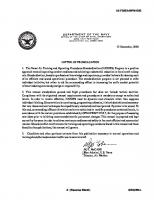
TP 7245E 1 of 2 AD Number: CF-2019-37
EMERGENCY AIRWORTHINESS DIRECTIVE This Airworthiness Directive (AD) is issued pursuant to Canadian Aviation Regulation (CAR) 521.427. No person shall conduct a take-off or permit a take-off to be conducted in an aircraft that is in their legal custody and control, unless the requirements of CAR 605.84 pertaining to ADs are met. Standard 625 Aircraft Equipment and Maintenance Standards Appendix H provides information concerning alternative means of compliance (AMOC) to ADs. Number:
Effective Date:
CF-2019-37
26 October 2019
ATA:
Type Certificate:
72
A-236
Subject: Engine - Aircraft Flight Manual – Operating Limitations Applicability: Airbus Canada Limited Partnership (formerly C Series Aircraft Limited Partnership (CSALP), Bombardier Inc.) aeroplanes: Model BD-500-1A10, serial numbers 50001 and subsequent for aeroplanes with PW1524G engines, Model BD-500-1A11, serial numbers 55001 and subsequent for aeroplanes with PW1521G-3 or PW1524G-3 engines. Compliance: Within 7 days from the effective date of this AD, unless already accomplished. Background: Several occurrences of engine in-flight shutdowns (IFSDs) were reported on Airbus Canada Limited Partnership BD-500 family aeroplanes. Investigations are ongoing to determine the root cause. Preliminary investigation results indicate high altitude climbs at higher thrust settings for engines with certain thrust ratings may be a contributor. This condition, if not corrected, could lead to an uncontained failure of the engine and damage to the aeroplane. To address this potentially unsafe condition, this AD introduces a new Aircraft Flight Manual (AFM) limitation and normal procedure to limit the engine N1 setting to 94% while above 29000 feet. This AD is considered an interim action and further AD action may follow. Corrective Actions: A. Amend the applicable AFM, section Limitations, to incorporate the limitation as specified in Figure 1 of this AD, and section Normal Procedures, to replace the “High altitude climb check (before reaching 35000 ft.)” as specified in Figure 2 of this AD. Figure 1 Limitation Engine operating limits Above 29000 feet, the maximum N1 setting is 94% N1. Any exceedance of more than 20 continuous seconds must be reported.
Print Date: 2019-12-04
CF-2019-37 2 of 2 Figure 2 Normal Procedure High altitude climb check
CAUTION Before initiation of step climbs above 29000 feet, the autothrottle must be selected off to respect the 94% N1 limitation. Before reaching 29000 feet: (1) Autothrottle........................................................................ Select off (2) N1 .............................................................................Not above 94%
CAUTION If still in icing conditions, climb must be stopped at 35000 feet. Failure to select WING ANTIICE to OFF above 35000 feet could result in engine nacelle overheating, and trigger engine fire warnings. Before reaching 35000 feet: (3) ANTI-ICE, WING........................................................................ OFF (4) Avoid icing conditions. When stabilized in cruise: (5) Autothrottle .....................................................................As required (6) N1............................................................... Monitor, not above 94%
B. Inform all flight crews of the new procedure and thereafter operate the aeroplane accordingly. Authorization: For the Minister of Transport, ORIGINAL SIGNED BY
Rémy Knoerr Chief, Continuing Airworthiness Issued on 25 October 2019 Contact: Brian Daly, Continuing Airworthiness, Ottawa, telephone 888-663-3639, facsimile 613-996-9178 or e-mail [email protected] or any Transport Canada Centre.
Print Date: 2019-12-04
O
Transmittal letter
This is the EgyptAir Airplane Flight Manual, Issue No. 013. To bring this manual up to date, remove old pages and insert revised pages as follows: Chapter / Section
Remove page(s):
Insert page(s):
Title page
00−00−All
00−00−All
Change record
00−02−43 to 00−02−44
00−02−43 to 00−02−44
List of effective pages
00−03−1 to 00−03−14
00−03−1 to 00−03−14
Option list
00−04−1 to 00−04−2
00−04−1 to 00−04−2
Non−normal procedures
04−00−14 to 04−00−15
04−00−14 to 04−00−15
04−04−3 to 04−04−4
04−04−3 to 04−04−4
04−08−10
04−08−10
04−08−12
04−08−12
Supplements
04−08−14
04−08−14
04−15−21 to 04−15−22
04−15−21 to 04−15−22
04−18−4 to 04−18−5
04−18−4 to 04−18−5
04−18−8 to 04−18−10
04−18−8 to 04−18−10
04−21−1
04−21−1
04−21−9 to 04−21−11
04−21−9 to 04−21−11
04−21−14 to 04−21−24
04−21−14 to 04−21−24
06−00−00−1
06−00−00−1
06−06−01−5
06−06−01−5 06−07−00−1 to 06−07−00−2 06−07−01−1 to 06−07−01−6
AFM
DOT approved
Page 1
BD500−3AB48−32200−00 (309) Print Date: 2019-12-04
Issue 013, Sep 23/2019
O
Transmittal letter
Chapter / Section
Remove page(s):
Insert page(s):
06−19−00−1
06−19−00−1
06−19−01−1 to 06−19−01−4
06−19−01−1 to 06−19−01−6
Page 2
DOT approved
AFM
Issue 013, Sep 23/2019
BD500−3AB48−32200−00 (309) Print Date: 2019-12-04
O
Model BD−500−1A11
EgyptAir
Airplane Flight Manual AFM
BD500−3AB48−32200−00 (309) Issue No. 013
Copyright © 2018 − 2019, Bombardier Inc. All rights reserved. No part of this work may be reproduced or copied in any form or by any means without written permission of Bombardier Inc. The Bombardier and CSeries logos are registered trademarks of Bombardier Inc. Manufacturer:
B
AFM
Bombardier Inc. Bombardier Aerospace Commercial Aircraft Customer Services 123 Garratt Blvd., Toronto, Ontario Canada M3K 1Y5
DOT approved
Page 00−00−1
BD500−3AB48−32200−00 (309) Print Date: 2019-12-04
Issue 013, Sep 23/2019
O The information, technical data and the designs disclosed herein are the exclusive property of Bombardier Inc. or contain proprietary rights of others and are not to be used or disclosed to others without the written consent of Bombardier Inc. The recipient of this document, by its retention and use, agrees to hold in confidence the technical data and designs contained herein. The foregoing shall not apply to persons having proprietary rights to such information, technical data or such designs to the extent that such rights exist.
Page 00−00−2
DOT approved
AFM
Issue 013, Sep 23/2019
BD500−3AB48−32200−00 (309) Print Date: 2019-12-04
Technical Publications Comment form
B
TO: MCR FOCAL, TECHNICAL PUBLICATIONS Name of airline: BOMBARDIER AEROSPACE 123 GARRATT BLVD. TORONTO, ONTARIO, CANADA, M3K 1Y5 Bombardier reference #: MAIL STOP: N42−25 FAX: (416) 375−4538 E−MAIL ADDRESS: [email protected] Date:
ALL fields marked with an asterisk * are required Contact information *Name: *Corporation name:
*Dept name / Code:
Address:
City:
Province/State:
Postal code / Zip:
Country:
*Telephone:
Mobile/Cell phone:
Fax number:
*E−mail:
I would like to receive notification of actions on this request. NOTE: Responses will only be sent by electronic mail.
Page 1
July 23/2014
Print Date: 2019-12-04
Technical Publications Comment form
B
Publication information *Aircraft type:
*Aircraft model:
*Publication Module Code (PMC):
*Publication title:
*Media type:
*Issue date:
Paper Disk
*Chapter/Section/Page:
*Issue number:
Web
*Section title:
Originator’s reference number:
*Comments:
Reason for change:
Reference data provided:
Yes
No
Description:
Page 2
July 23/2014
Print Date: 2019-12-04
O
Approval page
Airplane Flight Manual
Model BD−500−1A11
Registration number: . . . . . . . . . . . . . . . . . . . . . .
Manufacturer’s serial no: . . . . . . . . . . . . . . . . . . .
ORIGINAL SIGNED W. Istchenko Approved by the Chief, Flight Test for the Director, National Aircraft Certification, Transport Canada.
Jul 08/2016 Date of approval: . . . . . . . . . . . . . . . . . . . . . . . . . .
AFM
DOT approved
Page 00−01−1
BD500−3AB48−32200−00 (309) Print Date: 2019-12-04
Issue 011, Jan 11/2019
O
Approval page
This page intentionally left blank
Page 00−01−2
DOT approved
AFM
Issue 011, Jan 11/2019
BD500−3AB48−32200−00 (309) Print Date: 2019-12-04
O
Change record
The Airplane Flight Manual is valid only when all the issued revisions are incorporated. Record the date you insert each revision in your manual. Issue / DOT approval
Signature / Date incorporated
Description of change
Issue 001 Jul 08/2016 W. Istchenko
Description of change: Initial issue.
Issue 002 Sep 06/2016 W. Istchenko
Description of change: Introduces the changes that follow:
Signature on file Jul 08/2016
Sections affected: All
•
Update the aircraft weights, APU bleed limits, and noise data.
•
Update avionics information to lift some limitations.
•
Extensive revision to include CAFM and the PW1521G engine.
Signature on file Sep 06/2016
Sections affected: Front matter − Option list Chapter 1 − Introduction
•
Definitions
•
Abbreviations
Chapter 2 − Limitations
AFM
•
Structural weight limitation
•
Center of gravity limits
•
Electronic checklist (ECL)
•
Demonstrated crosswind (takeoff and landing)
DOT approved
Page 00−02−1
BD500−3AB48−32200−00 (309) Print Date: 2019-12-04
Issue 012, Jul 22/2019
O
Change record
Issue / DOT approval
Description of change
•
Operation in icing conditions
•
Operation on contaminated runways
•
Obstacle clearance
•
Runway slopes
•
Tailwind conditions
•
Runway width
•
APU bleed
•
Displays
•
Flight Management System (FMS)
•
Engine types
•
Thrust management data
•
Engine operating procedure limits due to wind
Signature / Date incorporated
Chapter 3 − Normal procedures
•
Before taxi
•
After takeoff
•
Before landing
Chapter 4 − Non-normal procedures
•
Landing and go-around speeds
•
Landing distance factors
•
Unreliable airspeed
Chapter 5 − Performance
•
All sections affected
Page 00−02−2
DOT approved
AFM
Issue 011, Jan 11/2019
BD500−3AB48−32200−00 (309) Print Date: 2019-12-04
Issue / DOT approval
Change record
O
Description of change
Signature / Date incorporated
Chapter 6 − Supplements List of supplements Supplement 1 − Noise characteristics or
•
Certificated noise levels
Supplement 1A − Noise characteristics
•
Certificated noise levels
Supplement 2 − Operation on contaminated runways Issue 003 Oct 12/2016 W. Istchenko
Description of change: Introduces the changes that follow:
•
Update structural weight and center of gravity limits.
•
Update limitations APU bleed limits and fuel data.
•
Update avionics information to lift some limitations.
•
Update procedures to add new steps.
Signature on file Oct 12/2016
•
Update structural weight and center of gravity limits.
•
Include changes due to new wing anti-ice limitations
•
Sections affected:
AFM
DOT approved
Page 00−02−3
BD500−3AB48−32200−00 (309) Print Date: 2019-12-04
Issue 012, Jul 22/2019
O
Change record
Issue / DOT approval
Description of change
Signature / Date incorporated
Chapter 2− Limitations
•
Kind of airplane operation
•
Structural weight limitation
•
Center of gravity limits
•
Flap extended speed
•
Altitude and speed operating limits
•
Operation in icing conditions
•
Occupant limits
•
Electronic Checklist (ECL)
•
Autopilot engagement
•
Autothrottle
•
APU bleed
•
Flight spoilers
•
Fuel grades
•
Fuel additives
•
Flight Management System (FMS)
Chapter 3 − Normal procedures
•
Introduction
•
Power-on
•
Before takeoff
•
Shutdown
Chapter 4 − Non-normal procedures
•
Landing distance factors
Page 00−02−4
DOT approved
AFM
Issue 011, Jan 11/2019
BD500−3AB48−32200−00 (309) Print Date: 2019-12-04
Issue / DOT approval
Change record
O
Description of change
Signature / Date incorporated
•
RUDDER FAIL (warning)
•
GROUND SPOILER FAIL (caution)
•
Rudder pedal jammed
•
GROUND SPOILER FAIL (caution)
•
HYD 1 LO PRESS (caution)
•
HYD PUMP 2B FAIL (caution)
•
HYD PUMP 3B FAIL (caution)
•
ICE (caution)
•
FMS OEI PERF ACTIVE (caution)
•
FMS PERF DEP VSPEEDS (caution)
•
ENG SETTING MISMATCH (caution)
Chapter 5 − Performance
•
Demonstrated runway width
•
Demonstrated crosswind (takeoff and landing)
•
Takeoff performance calculations
Chapter 6 − Supplements List of supplements Supplement 6 − Operational capability
•
RVSM
•
Automatic Surveillance Dependant Broadcast (ADS-B)
Supplement 8 − Category II operations Supplement 12 − Derated thrust and reduced thrust takeoff
AFM
DOT approved
Page 00−02−5
BD500−3AB48−32200−00 (309) Print Date: 2019-12-04
Issue 011, Jan 11/2019
O
Change record
Issue / DOT approval
Description of change
Signature / Date incorporated
Supplement 16 − Head Up Display (HUD) system
Issue 004 Nov 10/2016 W. Istchenko
•
Introduction
•
Limitations
•
Non−normal procedures
Description of change: Introduces the changes that follow:
•
Removal of the FAA fuel loads limitation.
Signature on file Nov 10/2016
•
Reinstated structural weights and CG charts from previous issue.
•
Add new abbreviations for Configuration deviation list.
•
Add new Appendix − Configuration deviation list.
•
Add new Supplement 5 − Operation with airplane systems inoperative.
•
Editorial. Updates to the option list, Supplement 1, Supplement 6, and Supplement 16 to align with content applicability.
Sections affected: Option list
Page 00−02−6
DOT approved
AFM
Issue 012, Jul 22/2019
BD500−3AB48−32200−00 (309) Print Date: 2019-12-04
Issue / DOT approval
Change record
O
Description of change
Signature / Date incorporated
Chapter 1 − Introduction
•
Abbreviations
Chapter 2− Limitations
•
Structural weight limitation
•
Center of gravity limits
•
Fuel load
Chapter 6 − Supplements List of supplements Supplement 1 − Noise characteristics
•
Certification airplane configuration
Supplement 5 − Operation with airplane systems inoperative Supplement 6 − Operational capabilities
•
Communications
Supplement 16 − Head Up Display (HUD) system Chapter 7 − Appendix − Configuration deviation list
Issue / DOT approval Issue 005 Dec 08/2016 W. Istchenko
AFM
Signature / Date incorporated
Description of change Description of change: Introduces the changes that follow:
•
Revised zones for takeoff in CG figures.
•
Add warning for the single engine flight director/autopilot disconnect.
Signature on file Dec 08/2016
DOT approved
Page 00−02−7
BD500−3AB48−32200−00 (309) Print Date: 2019-12-04
Issue 012, Jul 22/2019
O
Change record
Issue / DOT approval
Description of change
Signature / Date incorporated
•
Update electronic checklist verification.
•
Add new Dual FMS failure procedure and modify 2 FMS procedures.
•
Revise a restricted takeoff procedural footnote.
•
Update limitations and procedures to cover the new engine relight limits.
•
Update fuel temperature limitation.
•
Add the takeoff and landing awareness function.
•
Update the ditching and forced landing procedures to add SMS runway option.
•
Editorial changes to the performance conditions and configurations, and noise characteristics (FAA).
Sections affected: Front matter − Option list Chapter 2 − Limitations
•
Center of gravity limits
•
Altitude and speed operating limits
Page 00−02−8
DOT approved
AFM
Issue 011, Jan 11/2019
BD500−3AB48−32200−00 (309) Print Date: 2019-12-04
Issue / DOT approval
Change record
O
Description of change
Signature / Date incorporated
•
Electronic checklist
•
Flight director
•
Fuel temperature
•
Engine operating procedure limits due to wind
Chapter 3 − Normal procedures
•
Takeoff and landing awareness function
Chapter 4 − Non-normal procedures
•
Ditching
•
Forced landing
•
FMS 1 FAIL (Caution)
•
FMS 2 FAIL (Caution)
•
Dual FMS failure
•
DUAL ENG FAIL (Warning)
•
L ENG FAIL (Caution)
•
R ENG FAIL (Caution)
•
Relight – Left engine
•
Relight – Right engine
Chapter 5 − Performance
•
Performance conditions and configuration
Chapter 6 − Supplements Supplement 1A − Noise characteristics
•
AFM
Certification airplane configuration
DOT approved
Page 00−02−9
BD500−3AB48−32200−00 (309) Print Date: 2019-12-04
Issue 011, Jan 11/2019
O
Change record
Issue / DOT approval
Description of change
Issue 006 Apr 12/2017 W. Istchenko
Description of change: Introduces the changes that follow:
•
Update of the fuel load and fuel additive limitations.
•
Removal of the airspeed note in procedures.
Signature / Date incorporated Signature on file Apr 12/2017
•
Editorial changes to add the −3 suffix to the PW1521G engine nomenclature.
•
Add FAA limitations for the use of autopilot or flight director.
•
Revision to the windmill relight envelope and applicable non-normal procedures.
•
Extensive revision to include new CAFM version 4.3.0 data and the PW1524G−3 engine.
Sections affected: Front matter − Option list Chapter 1 − Introduction
•
Definitions
Chapter 2 − Limitations
•
Kinds of airplane operation
•
Structural weight limitation
Page 00−02−10
DOT approved
AFM
Issue 012, Jul 22/2019
BD500−3AB48−32200−00 (309) Print Date: 2019-12-04
Issue / DOT approval
Change record
O
Description of change
Signature / Date incorporated
•
Center of gravity limits
•
Altitude and speed operating limits
•
Flight in icing conditions
•
Wing anti−ice
•
Approach and landing in icing conditions
•
Runway slopes
•
Tailwind conditions
•
Automatic Flight Control System (AFCS)
•
APU bleed air
•
Slats/flaps
•
Fuel load
•
Fuel additives
•
Displays
•
Flight Management System (FMS)
•
Engine types
•
Thrust management data
•
Engine operating procedure limits due to wind
Chapter 3 − Normal procedures
AFM
•
Before taxi
•
Before takeoff
•
After takeoff
•
Before landing
DOT approved
Page 00−02−11
BD500−3AB48−32200−00 (309) Print Date: 2019-12-04
Issue 011, Jan 11/2019
O
Change record
Issue / DOT approval
Description of change
Signature / Date incorporated
Chapter 4 − Non−normal procedures
•
Landing distance factors
•
GND SPOILER FAIL (Caution)
•
HYD 1 LO PRESS (Caution)
•
DUAL ENG FAIL (Warning)
•
L ENG FAIL (Caution)
•
R ENG FAIL (Caution)
•
Relight − Left engine
•
Relight − Right engine
Chapter 5 − Performance
•
Complete revision includes all sections
Chapter 6 − Supplements List of supplements Supplement 1 − Noise characteristics or
•
Certification airplane configuration
•
Certificated noise levels
Supplement 1A − Noise characteristics
•
Certification airplane configuration
•
Certificated noise levels
Supplement 2 − Operation on contaminated runways Supplement 3 − Landing on wet grooved or porous friction course runways
Page 00−02−12
DOT approved
AFM
Issue 011, Jan 11/2019
BD500−3AB48−32200−00 (309) Print Date: 2019-12-04
Issue / DOT approval
Change record
O
Description of change
Signature / Date incorporated
Supplement 5 − Operation with airplane systems inoperative
•
Introduction
•
Limitations
•
Non-normal procedures
•
Performance
Supplement 8 − Category II operations Supplement 12 − Derated thrust and reduced thrust takeoff
•
Limitations
•
Normal procedures
•
Performance
•
Supplements
Issue / DOT approval Issue 007 Aug 31/2017 W. Istchenko
Signature / Date incorporated
Description of change Description of change: Introduces the changes that follow:
•
Remove autothrottle limitation on approach.
•
Define new VAPP and VREF parameters.
Signature on file Aug 31/2017
•
AFM
Add structural weights, center of gravity limits and noise data.
DOT approved
Page 00−02−13
BD500−3AB48−32200−00 (309) Print Date: 2019-12-04
Issue 012, Jul 22/2019
O
Change record
Issue / DOT approval
Description of change
Signature / Date incorporated
•
Extensive revision of the Appendix chapter to include revised and new CDL items.
•
Add new Supplement 18 − Operation with tailwinds up to 15 kts.
•
Add new Supplement 20 − Alternate forward center of gravity.
•
Update crosswind and restricted takeoff information.
•
Add new limitations to Supplement 5.
•
Various updates to normal and non−normal procedures.
•
Add applicable abbreviations to operation speed titles.
•
Add new Supplement for approaches with glidepath angles greater than 3.5 degrees, up to 3.8 degrees inclusively.
Sections affected: Front matter − Option list Chapter 1 − Introduction
•
Definitions
Page 00−02−14
DOT approved
AFM
Issue 011, Jan 11/2019
BD500−3AB48−32200−00 (309) Print Date: 2019-12-04
Issue / DOT approval
Change record
O
Description of change
Signature / Date incorporated
•
Distances
•
Abbreviations
Chapter 2 − Limitations
•
Structural weight limitation
•
Center of gravity limits
•
Flaps extended speed (VFE)
•
Maximum landing gear operating speed (VLO)
•
Maximum landing gear extended speed (VLE)
•
Turbulence penetration speed (VRA)
•
Speed corrections for approach and landing in icing conditions with FLAP 5
•
Autothrottle
•
Engine shutdown
•
Engine operating procedure limits due to wind
Chapter 3 − Normal procedures
•
Power-on
•
Before taxi
•
Before takeoff
•
Descent and approach
Chapter 4 − Non−normal procedures
•
AFM
Landing and go-around speeds
DOT approved
Page 00−02−15
BD500−3AB48−32200−00 (309) Print Date: 2019-12-04
Issue 011, Jan 11/2019
O
Change record
Issue / DOT approval
Description of change
•
Landing distance factors
•
Spoiler levers jammed
•
XPDR 1 FAIL (Caution)
•
XPDR 2 FAIL (Caution)
•
FMS 1 FAIL (Caution)
•
FMS 2 FAIL (Caution)
•
L ENG FIRE (Warning)
•
Shutdown - Left engine
•
Shutdown - Right engine
Signature / Date incorporated
Chapter 5 − Performance
•
Demonstrated crosswind (takeoff and landing)
•
Takeoff performance calculations
•
Landing distance and speed
Chapter 6 − Supplements List of supplements Supplement 1 − Noise characteristics or
•
Certification airplane configuration
•
Certificated noise levels
Supplement 1A − Noise characteristics
•
Certification airplane configuration
•
Certificated noise levels
Page 00−02−16
DOT approved
AFM
Issue 011, Jan 11/2019
BD500−3AB48−32200−00 (309) Print Date: 2019-12-04
Issue / DOT approval
Change record
O
Description of change
Signature / Date incorporated
Supplement 2 − Operation on contaminated runways
•
Performance
Supplement 3 − Landing on wet grooved or porous friction course runways
•
Dispatch landing performance
Supplement 5 − Operation with airplane systems inoperative
•
Limitations
•
Non-normal procedures
•
Performance
Supplement 8 − Category II operations
•
Autothrottle
Supplement 9 − Approaches with glidepath angles greater than 3.5 degrees, up to 3.8 degrees Supplement 18 − Operation with tailwinds up to 15 kts Supplement 20 − Alternate forward center of gravity Chapter 7 − Appendix
•
AFM
Configuration Deviation List
DOT approved
Page 00−02−17
BD500−3AB48−32200−00 (309) Print Date: 2019-12-04
Issue 012, Jul 22/2019
O
Change record
Issue / DOT approval
Description of change
Issue 008 Jan 16/2018 W. Istchenko
Description of change: Introduces the changes that follow:
•
Extensive revision of non-normal procedures to update and align OLD factors.
Signature / Date incorporated Signature on file Jan 16/2018
•
Update runway width information.
•
Removal of altitude limitation for operation of the APU generator.
•
Simplification of electrical non−normal procedures to allow MMEL dispatch with a failed generator.
•
Update to supplement 16 Head Up Display (HUD) system.
•
Add structural weights, center of gravity limits and noise data.
•
Various updates to all sections.
•
Change a switch label.
Sections affected:
Page 00−02−18
DOT approved
AFM
Issue 012, Jul 22/2019
BD500−3AB48−32200−00 (309) Print Date: 2019-12-04
Issue / DOT approval
Change record
O
Description of change
Signature / Date incorporated
Front matter
•
Option list
•
Service bulletin list
•
Modification list
Chapter 1 − Introduction
•
Service bulletins
•
Modifications
Chapter 2 − Limitations
•
Structural weight limitation
•
Center of gravity limits
•
Autothrottle
•
APU operation
•
APU electrical
•
APU bleed air
•
Flight management system (FMS)
•
Takeoff and Landing Awareness Function (TLAF)
•
Engine shutdown
Chapter 4 − Non−normal procedures
AFM
•
EMERGENCY DESCENT (Warning)
•
EQUIP BAY OVHT (Warning)
•
EMERGENCY DESCENT (Caution)
•
L BLEED OVHT (Caution)
DOT approved
Page 00−02−19
BD500−3AB48−32200−00 (309) Print Date: 2019-12-04
Issue 012, Jul 22/2019
O
Change record
Issue / DOT approval
Description of change
•
L PACK FAIL (Caution)
•
R BLEED OVHT (Caution)
•
R PACK FAIL (Caution)
•
RAM AIR FAIL (Caution)
•
XBLEED FAIL (Caution)
•
Emergency descent
•
Unpressurized flight procedure
•
Ditching
•
Forced landing
•
EMER PWR ONLY (Warning)
•
AC BUS 1 (Caution)
•
AC BUS 2 (Caution)
•
APU GEN FAIL (Caution)
•
DC ESS BUS 1 (Caution)
•
DC ESS BUS 2 (Caution)
•
L GEN FAIL (Caution)
•
L GEN OIL (Caution)
•
R GEN FAIL (Caution)
•
R GEN OIL (Caution)
•
FLT CTRL DIRECT (Warning)
•
RUDDER FAIL (Warning)
•
FLAP FAIL (Caution)
•
FLT CTRL DIRECT (Caution)
Signature / Date incorporated
Page 00−02−20
DOT approved
AFM
Issue 012, Jul 22/2019
BD500−3AB48−32200−00 (309) Print Date: 2019-12-04
Issue / DOT approval
AFM
Change record
O
Description of change
Signature / Date incorporated
•
FLT CTRL DIRECT ADS (Caution)
•
FLT CTRL DIRECT IRS (Caution)
•
SLAT FAIL (Caution)
•
SLAT SKEW (Caution)
•
SLAT−FLAP FAIL (Caution)
•
SLAT−FLAP LEVER FAIL (Caution)
•
Rudder pedal jammed
•
Slat−flap lever jammed
•
HYD 1 HI TEMP (Caution)
•
HYD 1 LO PRESS (Caution)
•
HYD 1−2 LO PRESS (Caution)
•
HYD 1−3 LO PRESS (Caution)
•
HYD 2 HI TEMP (Caution)
•
HYD 2 LO PRESS (Caution)
•
HYD 2−3 LO PRESS (Caution)
•
HYD EDP 1A FAIL (Caution)
•
HYD EDP 2A FAIL (Caution)
•
HYD RAT PUMP FAIL (Caution)
•
L WING A/ICE OVHT (Caution)
•
R WING A/ICE OVHT (Caution)
•
ENG DSPL MISCOMPARE (Caution)
•
Unreliable airspeed
•
BRAKE FAIL (Caution)
DOT approved
Page 00−02−21
BD500−3AB48−32200−00 (309) Print Date: 2019-12-04
Issue 012, Jul 22/2019
O
Change record
Issue / DOT approval
Description of change
•
L BRAKE FAIL (Caution)
•
NORM BRAKE FAIL (Caution)
•
R BRAKE FAIL (Caution)
•
WOW FAIL (Caution)
•
FMS 1 FAIL (Caution)
•
FMS 2 FAIL (Caution)
•
FMS FUEL (Caution)
•
UNABLE RNP (Caution)
•
DUAL ENG FAIL (Warning)
•
L REVERSER FAIL (Caution)
•
L THROTTLE FAIL (Caution)
•
R REVERSER FAIL (Caution)
•
R THROTTLE FAIL (Caution)
•
Relight − Left engine
•
Relight − Right engine
•
Shutdown − Left engine
•
Shutdown − Right engine
•
Smoke/fire/fumes procedure
Signature / Date incorporated
Chapter 5 − Performance
•
Introduction
Chapter 6 − Supplements List of supplements
Page 00−02−22
DOT approved
AFM
Issue 012, Jul 22/2019
BD500−3AB48−32200−00 (309) Print Date: 2019-12-04
Issue / DOT approval
Change record
O
Description of change
Signature / Date incorporated
Supplement 1 − Noise characteristics or
•
Certification airplane configuration
•
Certificated noise levels
Supplement 1A − Noise characteristics
•
Certification airplane configuration
•
Certificated noise levels
Supplement 3 − Landing on wet grooved or porous friction course runways
•
Performance
Supplement 5 − Operation with airplane systems inoperative
•
Limitations
•
Non-normal procedures
•
Performance
Supplement 16 − Head Up Display (HUD) system
•
Introduction
•
Limitations
•
Non-normal procedures
Supplement 18 − Operation with tailwinds up to 15 kts
AFM
DOT approved
Page 00−02−23
BD500−3AB48−32200−00 (309) Print Date: 2019-12-04
Issue 012, Jul 22/2019
O
Change record
Issue / DOT approval
Description of change
Issue 009 Aug 06/2018 W. Istchenko
Description of change: Introduces the changes that follow:
•
Remove FAA limitation on maximum occupants.
Signature / Date incorporated Signature on file Aug 06/2018
•
Add Category III and autoland operational capabilities to Supplement 8.
•
Revise limitations, procedures, performance and supplements to include Build 8.0A avionic updates.
•
Add new performance data for BTMS inoperative.
•
Editorial change to non-normal procedures.
•
Updates to performance text.
Sections affected: Front matter
•
Option list
•
Service bulletin list
•
Modification list
Page 00−02−24
DOT approved
AFM
Issue 012, Jul 22/2019
BD500−3AB48−32200−00 (309) Print Date: 2019-12-04
Issue / DOT approval
Change record
O
Description of change
Signature / Date incorporated
Chapter 1 − Introduction
•
Distances
•
Abbreviations
Chapter 2 − Limitations
•
Center of gravity limits
•
Maximum occupants
•
Autopilot engagement
•
Emergency descent mode
•
ILS approach
•
Flight director
•
Displays
•
Flight management system (FMS)
•
Thrust management data
Chapter 4 − Non−normal procedures
AFM
•
AIR SYS ESS CTLR FAIL (Caution)
•
L AIR SYS CTLR FAIL (Caution)
•
L BLEED OVHT (Caution)
•
L PACK FAIL (Caution)
•
R AIR SYS CTLR FAIL (Caution)
•
R BLEED OVHT (Caution)
•
R PACK FAIL (Caution)
•
XBLEED FAIL (Caution)
•
EMER PWR ONLY (Warning)
DOT approved
Page 00−02−25
BD500−3AB48−32200−00 (309) Print Date: 2019-12-04
Issue 012, Jul 22/2019
O
Change record
Issue / DOT approval
Description of change
•
DC ESS BUS 1 (Caution)
•
DC ESS BUS 2 (Caution)
•
EQUIP BAY SMOKE FAIL (Caution)
•
FLT CTRL DIRECT (Warning)
•
FLT CTRL DIRECT (Caution)
•
SPOILER DEGRADED (Caution)
•
SPOILER FAIL (Caution)
•
HYD 1 LO PRESS (Caution)
•
L WING A/ICE OVHT (Caution)
•
R WING A/ICE OVHT (Caution)
•
Arcing, delaminated, shattered, or cracked window or windshield
•
IPC 1 FAIL (Caution)
•
IPC 2 FAIL (Caution)
•
GEAR FAIL (Caution)
•
L BRAKE FAIL (Caution)
•
R BRAKE FAIL (Caution)
•
WOW FAIL (Caution)
•
Low tire pressure landing procedure
•
> CABIN PRIORITY (Caution)
•
KU BAND ON (Caution)
•
FMS 1 FAIL (Caution)
•
FMS 2 FAIL (Caution)
Signature / Date incorporated
Page 00−02−26
DOT approved
AFM
Issue 012, Jul 22/2019
BD500−3AB48−32200−00 (309) Print Date: 2019-12-04
Issue / DOT approval
Change record
O
Description of change
Signature / Date incorporated
•
L ENG FAIL (Caution)
•
R ENG FAIL (Caution)
•
Smoke/fire/fumes procedure
Chapter 5 − Performance
•
Introduction
•
Thrust settings
•
Takeoff performance
•
Approach and landing
Chapter 6 − Supplements List of supplements Supplement 3 − Landing on wet grooved or porous friction course runways
•
Performance
Supplement 5 − Operation with airplane systems inoperative
•
Non−normal procedures
•
Performance
Supplement 6 − Operational capabilities
•
Limitations
•
Performance
Supplement 8 − Category II and Category III, autoland operations Supplement 12 − Derated thrust and reduced thrust takeoff
•
AFM
Normal procedures
DOT approved
Page 00−02−27
BD500−3AB48−32200−00 (309) Print Date: 2019-12-04
Issue 012, Jul 22/2019
O
Change record
Issue / DOT approval
Description of change
•
Signature / Date incorporated
Performance
Supplement 16 − Head Up Display (HUD) system
•
Limitations
Supplement 20 − Alternate forward center of gravity
•
Limitations
Issue / DOT approval Issue 010 Oct 11/2018 W. Istchenko
Description of change Description of change: Introduces the changes that follow:
•
Revise limitations to include FADEC v2.11 update.
Signature / Date incorporated Signature on file Oct 11/2018
Sections affected: Front matter
•
Service bulletin list
•
Modification list
Chapter 2 − Limitations
•
Engine operating limits
Page 00−02−28
DOT approved
AFM
Issue 012, Jul 22/2019
BD500−3AB48−32200−00 (309) Print Date: 2019-12-04
Issue / DOT approval Issue 011 Jan 11/2019 W. Istchenko
Change record
O
Description of change
Signature / Date incorporated
Description of change: Introduces the changes that follow:
•
Updates for the installation of new IASC 5.0 software change.
Signature on file Jan 11/2019
•
Various updates to all sections.
•
Updates for the replacement of hydraulic systems 2 and 3 ACMPs.
•
Revise limitations, procedures and performance to include FADEC v2.10 and v2.11 update.
•
Add new Supplement 19 − ETOPS .
•
Add structural weights, center of gravity limits and noise data.
•
Add nacelle seals to Configuration Deviation List (CDL).
•
Update to non-normal procedures.
AFM
DOT approved
Page 00−02−29
BD500−3AB48−32200−00 (309) Print Date: 2019-12-04
Issue 012, Jul 22/2019
O
Change record
Issue / DOT approval
Description of change
Signature / Date incorporated
Sections affected: Front matter
•
Option list
•
Service bulletin list
•
Modification list
Chapter 2 − Limitations
•
Kinds of airplane operations
•
Structural weight limitation
•
Center of gravity limits
•
Altitude and speed operating limits
•
Wing anti-ice system
•
Flight Management System (FMS)
•
Engine relight
•
Engine operating procedure limits due to wind
Chapter 3 − Normal procedures
•
Before taxi
•
Before start
•
Shutdown
Chapter 4 − Non-normal procedures
•
Non-normal procedure format
•
EMERGENCY DESCENT (Warning)
•
CABIN ALT (Caution)
•
EMERGENCY DESCENT (Caution)
Page 00−02−30
DOT approved
AFM
Issue 012, Jul 22/2019
BD500−3AB48−32200−00 (309) Print Date: 2019-12-04
Issue / DOT approval
AFM
Change record
O
Description of change
Signature / Date incorporated
•
L BLEED OVHT (Caution)
•
L PACK FAIL (Caution)
•
R AIR SYS CTLR FAIL (Caution)
•
R BLEED OVHT (Caution)
•
R PACK FAIL (Caution)
•
XBLEED FAIL (Caution)
•
Emergency descent
•
Ditching
•
Forced landing
•
DC BUS 1 (Caution)
•
DC BUS 2 (Caution)
•
DC ESS BUS 2 (Caution)
•
DC ESS BUS 3 (Caution)
•
EQUIP BAY SMOKE FAIL (Caution)
•
FLT CTRL DIRECT (Warning)
•
L ELEVATOR FAIL (Warning)
•
R ELEVATOR FAIL (Warning)
•
RUDDER FAIL (Warning)
•
ADS DEGRADED (Caution)
•
FLAP FAIL (Caution)
•
FLT CTRL DIRECT (Caution)
•
FLT CTRL DIRECT ADS (Caution)
•
FLT CTRL DIRECT IRS (Caution)
DOT approved
Page 00−02−31
BD500−3AB48−32200−00 (309) Print Date: 2019-12-04
Issue 012, Jul 22/2019
O
Change record
Issue / DOT approval
Description of change
•
GND SPOILER FAIL (Caution)
•
L ELEVATOR FAIL (Caution)
•
PITCH AUTHORITY (Caution)
•
R ELEVATOR FAIL (Caution)
•
SLAT FAIL (Caution)
•
SLAT SKEW (Caution)
•
SLAT-FLAP FAIL (Caution)
•
SLAT-FLAP LEVER FAIL (Caution)
•
STAB DEGRADED (Caution)
•
STAB TRIM FAIL (Caution)
•
Rudder pedal jammed
•
Slat-flap lever jammed
•
FUEL CTR XFR FAIL (Caution)
•
FUEL IMBALANCE (Caution)
•
HYD 1 HI TEMP (Caution)
•
HYD 1 LO PRESS (Caution)
•
HYD 1-2 LO PRESS (Caution)
•
HYD 1-3 LO PRESS (Caution)
•
HYD 2 HI TEMP (Caution)
•
HYD 2 LO PRESS (Caution)
•
HYD 2-3 LO PRESS (Caution)
•
HYD 3 HI TEMP (Caution)
•
HYD 3 LO PRESS (Caution)
Signature / Date incorporated
Page 00−02−32
DOT approved
AFM
Issue 012, Jul 22/2019
BD500−3AB48−32200−00 (309) Print Date: 2019-12-04
Issue / DOT approval
AFM
Change record
O
Description of change
Signature / Date incorporated
•
HYD PUMP 2B FAIL (Caution)
•
HYD PUMP 3B FAIL (Caution)
•
ICE (Caution)
•
L WING A/ICE OVHT (Caution)
•
R WING A/ICE OVHT (Caution)
•
Arcing, delaminated, shattered or cracked window or windshield
•
DUAL ADS FAIL (Caution)
•
EFIS COMPARATOR FAIL (Caution)
•
IPC 1 FAIL (Caution)
•
IPC 2 FAIL (Caution)
•
Gear up or unsafe landing procedure
•
FMS 1 FAIL (Caution)
•
FMS 2 FAIL (Caution)
•
DUAL ENG FAIL (Warning)
•
ENG VIBRATION (Caution)
•
L ENG OPER DEGRADED (Caution)
•
L REVERSER FAIL (Caution)
•
L THROTTLE FAIL (Caution)
•
R ENG OPER DEGRADED (Caution)
•
R REVERSER FAIL (Caution)
•
R THROTTLE FAIL (Caution)
•
Relight − Left engine
DOT approved
Page 00−02−33
BD500−3AB48−32200−00 (309) Print Date: 2019-12-04
Issue 012, Jul 22/2019
O
Change record
Issue / DOT approval
Description of change
•
Relight − Right engine
•
Shutdown − Left engine
•
Shutdown − Right engine
•
EQUIP BAY SMOKE (Warning)
Signature / Date incorporated
Chapter 5 − Performance
•
Takeoff performance
Chapter 6 − Supplements List of supplements Supplement 1 − Noise characteristics
•
Certification airplane configuration
•
Certificated noise levels
Supplement 1A − Noise characteristics
•
Certification airplane configuration
•
Certificated noise levels
Supplement 5 − Operation with airplane systems inoperative
•
Non-normal procedures
Supplement 6 − Operational capabilities
•
Navigation
Supplement 8 − Category II, Category III autoland operations
•
Limitations
•
Supplements
Page 00−02−34
DOT approved
AFM
Issue 012, Jul 22/2019
BD500−3AB48−32200−00 (309) Print Date: 2019-12-04
Issue / DOT approval
Change record
O
Description of change
Signature / Date incorporated
Supplement 9 − Approaches with glidepath angles greater than 3.5 degrees, up to 3.8 degrees
•
Supplements
Supplement 12 − Derated thrust and reduce thrust takeoff
•
Limitations
•
Normal procedures
•
Performance
Supplement 16 − Head-Up Display (HUD) system
•
Non-normal procedures
Supplement 18 − Takeoff and landing with tailwinds greater than 10 kts
•
Limitations
•
Performance
Supplement 19 − ETOPS Supplement 20 − Alternate forward center of gravity
•
Limitations
Chapter 7 − Appendix − Configuration deviation list
AFM
•
54 − Nacelles/pylons
•
57 − Wing
•
71 − Power plant
DOT approved
Page 00−02−35
BD500−3AB48−32200−00 (309) Print Date: 2019-12-04
Issue 012, Jul 22/2019
O
Change record
Issue / DOT approval
Description of change
Issue 012 Jul 22/2019 W. Istchenko
Description of change: Introduces the changes that follow:
•
Add structural weights, center of gravity limits and noise data.
Signature / Date incorporated Signature on file Jul 22/2019
•
Editorial. Various updates to limitations and procedures.
•
Editorial. Various updates to limitations and procedures.
•
Configuration deviation list revised.
•
Update to crosswind limitations.
•
Add new AFIRS™ Iridium SATCOM system capability.
•
Editorial. Update to align with SB incorporation status: Remove Pre-SB content for BD500-314001, BD500-314002, and BD500-316001.
•
Add alternative for wing anti-ice test.
Page 00−02−36
DOT approved
AFM
Issue 012, Jul 22/2019
BD500−3AB48−32200−00 (309) Print Date: 2019-12-04
Issue / DOT approval
Change record
O
Description of change
Signature / Date incorporated
Sections affected: Front matter
•
Option list
•
Service bulletin list
•
Modification list
Chapter 1 − Introduction
•
Distances
Chapter 2 − Limitations
AFM
•
Structural weight limitation
•
Center of gravity limits
•
Design maneuvering speed
•
Air-conditioning
•
Autopilot engagement
•
Autothrottle
•
Flight director
•
APU start
•
APU operation
•
Displays
•
Flight Management System (FMS)
•
Takeoff and Landing Awareness Function (TLAF)
•
Engine operating procedure limits due to wind
DOT approved
Page 00−02−37
BD500−3AB48−32200−00 (309) Print Date: 2019-12-04
Issue 012, Jul 22/2019
O
Change record
Issue / DOT approval
Description of change
Signature / Date incorporated
Chapter 3 − Normal procedures
•
Before taxi
•
Takeoff and landing awareness function
Chapter 4 − Non-normal procedures
•
L BLEED LEAK (Caution)
•
R BLEED LEAK (Caution)
•
APU (Caution)
•
APU BLEED FAIL (Caution)
•
EMER PWR ONLY (Warning)
•
FLT CTRL DIRECT (Warning)
•
FLT CTRL DIRECT (Caution)
•
PITCH AUTHORITY (Caution)
•
ROLL AUTHORITY (Caution)
•
YAW AUTHORITY (Caution)
•
APU FUEL SOV FAIL (Caution)
•
FUEL CTR XFR FAIL (Caution)
•
FUEL TANK LO TEMP (Caution)
•
HYD 1 LO PRESS (Caution)
•
HYD 1-2 LO PRESS (Caution)
•
HYD 1-3 LO PRESS (Caution)
•
HYD 2 SOV FAIL (Caution)
•
HYD 2-3 LO PRESS (Caution)
Page 00−02−38
DOT approved
AFM
Issue 012, Jul 22/2019
BD500−3AB48−32200−00 (309) Print Date: 2019-12-04
Issue / DOT approval
AFM
Change record
O
Description of change
Signature / Date incorporated
•
HYD RAT PUMP FAIL (Caution)
•
ADS 1 PROBE HEAT FAIL (Caution)
•
ADS 1 SLIPCOMP FAIL (Caution)
•
ADS 2 PROBE HEAT FAIL (Caution)
•
ADS 2 SLIPCOMP FAIL (Caution)
•
ADS 3 PROBE HEAT FAIL (Caution)
•
ADS 3 SLIPCOMP FAIL (Caution)
•
ADS 4 PROBE HEAT FAIL (Caution)
•
ADS 4 SLIPCOMP FAIL (Caution)
•
ADS ISI PROBE HEAT (Caution)
•
ADS ISI SLIPCOMP FAIL (Caution)
•
DMC 1 FAIL (Caution)
•
EFIS MISCOMPARE (Caution)
•
ENG DSPL MISCOMPARE (Caution)
•
L CTP TUNING FAIL (Caution)
•
L-R RADIO TUNING (Caution)
•
BRAKE OVHT (Warning)
•
GEAR FAIL (Caution)
•
NOSE STEER FAIL (Caution)
•
NOSE TIRE LO PRESS (Caution)
•
WOW FAIL (Caution)
•
Low tire pressure landing procedure
•
> CABIN PRIORITY (Caution)
DOT approved
Page 00−02−39
BD500−3AB48−32200−00 (309) Print Date: 2019-12-04
Issue 012, Jul 22/2019
O
Change record
Issue / DOT approval
Description of change
•
KU BAND ON (Caution)
•
APPROACH NOT AVAIL (Caution)
•
GNSS NOT AVAIL (Caution)
•
L ENG EXCEEDANCE (Caution)
•
L ENG FAIL (Caution)
•
R ENG EXCEEDANCE (Caution)
•
R ENG FAIL (Caution)
•
Smoke/fire/fumes procedure
Signature / Date incorporated
Chapter 5 − Performance
•
Demonstrated crosswind (takeoff and landing)
Chapter 6 − Supplements Supplement 1 − Noise characteristics or
•
Certification airplane configuration
•
Certificated noise levels
Supplement 1A − Noise characteristics
•
Certification airplane configuration
•
Certificated noise levels
Supplement 2 − Operation on contaminated runways
•
Performance
Supplement 5 − Operation with airplane systems inoperative
•
Limitations
Page 00−02−40
DOT approved
AFM
Issue 012, Jul 22/2019
BD500−3AB48−32200−00 (309) Print Date: 2019-12-04
Issue / DOT approval
Change record
O
Description of change
Signature / Date incorporated
•
Non-normal procedures
•
Performance
Supplement 6 − Operational capabilities
•
Surveillance
•
Communications
Supplement 8 − Category II and Category III, autoland operations
•
Limitations
•
Performance
Supplement 9 − Approaches with glidepath angles greater than 3.5 degrees, up to 3.8 degrees
•
Introduction
•
Supplements
Supplement 12 − Derated thrust and reduced thrust takeoff
•
Limitations
•
Normal procedures
Supplement 16 − Head Up Display
•
Limitations
•
Non-normal procedures
Supplement 18 − Takeoff and landing with tailwinds greater than 10 kts
AFM
•
Introduction
•
Limitations DOT approved
Page 00−02−41
BD500−3AB48−32200−00 (309) Print Date: 2019-12-04
Issue 012, Jul 22/2019
O
Change record
Issue / DOT approval
Description of change
Signature / Date incorporated
Supplement 20 − Alternate forward center of gravity
•
Limitations
Chapter 7 − Appendix - Configuration deviation list
Issue 012A
•
Introduction
•
32 − Landing gear
•
33 − Lights
•
51 − Structures
•
52 − Doors
•
53 − Fuselage
•
54 − Nacelles/pylons
•
55 − Stabilizers
•
57 − Wing
•
78 − Exhaust
Description of change: Introduces the changes that follow:
•
Provide previously approved data:
Signature on file Aug 20/2019
ETOPS Improved calculated in-flight performance
Sections affected: Front matter − Option list Chapter 2 − Limitations
•
Kinds of airplane operations
Page 00−02−42
DOT approved
AFM
Issue 012A, Aug 20/2019
BD500−3AB48−32200−00 (309) Print Date: 2019-12-04
Issue / DOT approval
Change record
O
Description of change
Signature / Date incorporated
Chapter 6 − Supplements Supplement 5 − Operation with airplane systems inoperative
•
Performance
Supplement 19 − ETOPS
Issue / DOT approval Issue 013 Sep 23/2019 W. Istchenko
Description of change Description of change: Introduces the changes that follow:
•
Add new Supplement 7 for RNP − Authorization required operations.
Signature / Date incorporated Signature on file Sep 23/2019
•
Update the ETOPS supplement.
Sections affected: Front matter − Option list Chapter 4 − Non-normal procedures
AFM
•
FD FAIL (Caution)
•
DC BUS 1 (Caution)
•
DC ESS BUS 2 (Caution)
•
DC ESS BUS 3 (Caution)
•
IPC 1 FAIL (Caution)
•
IPC 2 FAIL (Caution)
•
FMS 1 FAIL (Caution)
DOT approved
Page 00−02−43
BD500−3AB48−32200−00 (309) Print Date: 2019-12-04
Issue 013, Sep 23/2019
O
Change record
Issue / DOT approval
Description of change
•
FMS 2 FAIL (Caution)
•
GNSS NOT AVAIL (Caution)
•
Dual FMS failure
•
Smoke/fire/fumes procedure
Signature / Date incorporated
Chapter 6 − Supplements List of supplements Supplement 6 − Operational capabilities
•
Navigation − FMS
Supplement 7 − RNP − Authorization required operations Supplement 19 − ETOPS
•
Introduction
•
Limitations
•
Normal procedures
Page 00−02−44
DOT approved
AFM
Issue 013, Sep 23/2019
BD500−3AB48−32200−00 (309) Print Date: 2019-12-04
O
List of effective pages
Page 00−00
Date
Page
All
* Sep 23/2019
00−01 −1 −2
Jan 11/2019 Jan 11/2019
00−02
Jul 22/2019 Jan 11/2019 Jul 22/2019 Jan 11/2019 Jan 11/2019 Jul 22/2019 Jul 22/2019 Jan 11/2019 Jan 11/2019 Jul 22/2019 Jan 11/2019 Jan 11/2019 Jul 22/2019 Jan 11/2019 Jan 11/2019 Jan 11/2019 Jul 22/2019 Jul 22/2019 Jul 22/2019 Jul 22/2019 Jul 22/2019 Jul 22/2019 Jul 22/2019 Jul 22/2019 Jul 22/2019 Jul 22/2019 Jul 22/2019 Jul 22/2019 Jul 22/2019 Jul 22/2019
−1 −2 −3 −4 −5 −6 −7 −8 −9 −10 −11 −12 −13 −14 −15 −16 −17 −18 −19 −20 −21 −22 −23 −24 −25 −26 −27 −28 −29 −30
Date −31 Jul 22/2019 −32 Jul 22/2019 −33 Jul 22/2019 −34 Jul 22/2019 −35 Jul 22/2019 −36 Jul 22/2019 −37 Jul 22/2019 −38 Jul 22/2019 −39 Jul 22/2019 −40 Jul 22/2019 −41 Jul 22/2019 −42 Aug 20/2019 −43 * Sep 23/2019 −44 * Sep 23/2019
00−03
−1 −2 −3 −4 −5 −6 −7 −8 −9 −10 −11 −12 −13 −14
* * * * * * * * * * * * * *
Sep 23/2019 Sep 23/2019 Sep 23/2019 Sep 23/2019 Sep 23/2019 Sep 23/2019 Sep 23/2019 Sep 23/2019 Sep 23/2019 Sep 23/2019 Sep 23/2019 Sep 23/2019 Sep 23/2019 Sep 23/2019
00−04
−1 −2
* Sep 23/2019 * Sep 23/2019
00−05
−1 −2
Jan 11/2019 Jan 11/2019
* The asterisk indicates pages changed, added or deleted.
AFM
DOT approved
Page 00−03−1
BD500−3AB48−32200−00 (309) Print Date: 2019-12-04
Issue 013, Sep 23/2019
O Page
List of effective pages
Date
Page
00−06
−1 −2
Jul 22/2019 Jan 11/2019
01−00
−1 −2
Jan 11/2019 Jan 11/2019
−1 −2 −3 −4 −5 −6 −7 −8 −9 −10 −11 −12 −13 −14 −15 −16 −17 −18 −19 −20 −21 −22 −23 −24 −25 −26
Jan 11/2019 Jan 11/2019 Jan 11/2019 Jan 11/2019 Jan 11/2019 Jan 11/2019 Jan 11/2019 Jan 11/2019 Jan 11/2019 Jul 22/2019 Jul 22/2019 Jul 22/2019 Jul 22/2019 Jan 11/2019 Jan 11/2019 Jan 11/2019 Jan 11/2019 Jan 11/2019 Jan 11/2019 Jan 11/2019 Jan 11/2019 Jan 11/2019 Jan 11/2019 Jan 11/2019 Jan 11/2019 Jan 11/2019
−1 −2 −3
Jul 22/2019 Jan 11/2019 Jan 11/2019
01−01
02−00
Date −4 −5 −6
Jul 22/2019 Jul 22/2019 Jul 22/2019
02−01
−1 −2
Jan 11/2019 Jan 11/2019
02−02
−1 −2 −3 −4 −5 −6 −7 −8
Aug 20/2019 Aug 20/2019 Aug 20/2019 Jul 22/2019 Jul 22/2019 Jul 22/2019 Jul 22/2019 Jul 22/2019
02−03
−1 −2 −3 −4 −5 −6
Jan 11/2019 Jan 11/2019 Jul 22/2019 Jul 22/2019 Jan 11/2019 Jan 11/2019
02−04
−1 −2 −3 −4 −5 −6 −7 −8
Jan 11/2019 Jan 11/2019 Jan 11/2019 Jan 11/2019 Jan 11/2019 Jan 11/2019 Jan 11/2019 Jan 11/2019
02−05
−1 −2
Jul 22/2019 Jan 11/2019
* The asterisk indicates pages changed, added or deleted.
Page 00−03−2
DOT approved
AFM
Issue 013, Sep 23/2019
BD500−3AB48−32200−00 (309) Print Date: 2019-12-04
O
List of effective pages
Page
Date
Page
Date
02−06
−1 −2
Jul 22/2019 Jan 11/2019
03−01
−1 −2
Jan 11/2019 Jan 11/2019
02−07
−1 −2 −3 −4 −5 −6
Jul 22/2019 Jan 11/2019 Jan 11/2019 Jan 11/2019 Jan 11/2019 Jan 11/2019
03−02
02−08
−1 −2
Jan 11/2019 Jan 11/2019
02−09
−1 −2
Jan 11/2019 Jan 11/2019
−1 −2 −3 −4 −5 −6 −7 −8 −9 −10
Jan 11/2019 Jan 11/2019 Jan 11/2019 Jan 11/2019 Jul 22/2019 Jul 22/2019 Jul 22/2019 Jul 22/2019 Jul 22/2019 Jan 11/2019
04−00
02−10
−1 −2 −3 −4
Jan 11/2019 Jan 11/2019 Jan 11/2019 Jan 11/2019
02−11
−1 −2
Jan 11/2019 Jan 11/2019
02−12
−1 −2
Jul 22/2019 Jul 22/2019
02−13
−1 −2 −3 −4 −5 −6
Jan 11/2019 Jan 11/2019 Jul 22/2019 Jul 22/2019 Jul 22/2019 Jan 11/2019
03−00
−1 −2
Jul 22/2019 Jan 11/2019
−1 Jan 11/2019 −2 Jul 22/2019 −3 Jan 11/2019 −4 Jul 22/2019 −5 Jan 11/2019 −6 Jul 22/2019 −7 Jul 22/2019 −8 Jul 22/2019 −9 Jan 11/2019 −10 Jul 22/2019 −11 Jul 22/2019 −12 Jul 22/2019 −13 Jul 22/2019 −14 * Sep 23/2019 −15 * Sep 23/2019 −16 Jul 22/2019 −17 Jan 11/2019 −18 Jan 11/2019
04−01
−1 −2
Jan 11/2019 Jan 11/2019
* The asterisk indicates pages changed, added or deleted.
AFM
DOT approved
Page 00−03−3
BD500−3AB48−32200−00 (309) Print Date: 2019-12-04
Issue 013, Sep 23/2019
O Page 04−02
List of effective pages
Date −1 −2 −3 −4 −5 −6 −7 −8 −9 −10 −11 −12 −13 −14 −15 −16 −17 −18 −19 −20 −21 −22 −23 −24 −25 −26 −27 −28 −29 −30 −31 −32 −33 −34
Page
Jul 22/2019 Jul 22/2019 Jan 11/2019 Jan 11/2019 Jan 11/2019 Jan 11/2019 Jan 11/2019 Jan 11/2019 Jan 11/2019 Jan 11/2019 Jan 11/2019 Jan 11/2019 Jan 11/2019 Jan 11/2019 Jan 11/2019 Jan 11/2019 Jan 11/2019 Jul 22/2019 Jul 22/2019 Jul 22/2019 Jul 22/2019 Jul 22/2019 Jul 22/2019 Jul 22/2019 Jul 22/2019 Jul 22/2019 Jul 22/2019 Jul 22/2019 Jul 22/2019 Jul 22/2019 Jul 22/2019 Jul 22/2019 Jul 22/2019 Jul 22/2019
Date −35 −36 −37 −38
Jul 22/2019 Jul 22/2019 Jul 22/2019 Jul 22/2019
04−03
−1 −2 −3 −4
Jan 11/2019 Jan 11/2019 Jan 11/2019 Jan 11/2019
04−04
−1 −2 −3 −4
Jan 11/2019 Jan 11/2019 * Sep 23/2019 * Sep 23/2019
04−05
−1 −2 −3 −4 −5 −6
Jan 11/2019 Jan 11/2019 Jan 11/2019 Jul 22/2019 Jul 22/2019 Jan 11/2019
04−06
−1 −2 −3 −4 −5 −6
Jan 11/2019 Jan 11/2019 Jan 11/2019 Jan 11/2019 Jan 11/2019 Jan 11/2019
04−07
−1 −2 −3 −4 −5 −6 −7 −8
Jan 11/2019 Jan 11/2019 Jan 11/2019 Jan 11/2019 Jan 11/2019 Jan 11/2019 Jan 11/2019 Jan 11/2019
* The asterisk indicates pages changed, added or deleted.
Page 00−03−4
DOT approved
AFM
Issue 013, Sep 23/2019
BD500−3AB48−32200−00 (309) Print Date: 2019-12-04
O
List of effective pages
Page
Date
Page
04−08
−1 Jul 22/2019 −2 Jan 11/2019 −3 Jul 22/2019 −4 Jul 22/2019 −5 Jul 22/2019 −6 Jul 22/2019 −7 Jul 22/2019 −8 Jul 22/2019 −9 Jul 22/2019 −10 * Sep 23/2019 −11 Jan 11/2019 −12 * Sep 23/2019 −13 Jan 11/2019 −14 * Sep 23/2019 −15 Jan 11/2019 −16 Jan 11/2019 −17 Jan 11/2019 −18 Jan 11/2019
04−09
−1 −2 −3 −4
Jan 11/2019 Jan 11/2019 Jan 11/2019 Jan 11/2019
04−10
−1 −2 −3 −4 −5 −6 −7 −8 −9 −10
Jan 11/2019 Jan 11/2019 Jan 11/2019 Jan 11/2019 Jan 11/2019 Jan 11/2019 Jan 11/2019 Jan 11/2019 Jan 11/2019 Jan 11/2019
04−11
Date −1 −2 −3 −4 −5 −6 −7 −8 −9 −10 −11 −12 −13 −14 −15 −16 −17 −18 −19 −20 −21 −22 −23 −24 −25 −26 −27 −28 −29 −30 −31 −32 −33 −34
Jan 11/2019 Jul 22/2019 Jan 11/2019 Jul 22/2019 Jan 11/2019 Jan 11/2019 Jan 11/2019 Jan 11/2019 Jan 11/2019 Jan 11/2019 Jan 11/2019 Jan 11/2019 Jan 11/2019 Jan 11/2019 Jan 11/2019 Jan 11/2019 Jan 11/2019 Jan 11/2019 Jan 11/2019 Jan 11/2019 Jan 11/2019 Jan 11/2019 Jan 11/2019 Jan 11/2019 Jul 22/2019 Jan 11/2019 Jan 11/2019 Jan 11/2019 Jan 11/2019 Jan 11/2019 Jan 11/2019 Jan 11/2019 Jan 11/2019 Jan 11/2019
* The asterisk indicates pages changed, added or deleted.
AFM
DOT approved
Page 00−03−5
BD500−3AB48−32200−00 (309) Print Date: 2019-12-04
Issue 013, Sep 23/2019
O Page
List of effective pages
Date −35 −36 −37 −38 −39 −40 −41 −42 −43 −44 −45 −46 −47 −48 −49 −50 −51 −52 −53 −54 −55 −56 −57 −58 −59 −60 −61 −62 −63 −64 −65 −66 −67 −68
Page
Jan 11/2019 Jul 22/2019 Jan 11/2019 Jul 22/2019 Jul 22/2019 Jul 22/2019 Jul 22/2019 Jan 11/2019 Jan 11/2019 Jan 11/2019 Jan 11/2019 Jan 11/2019 Jan 11/2019 Jan 11/2019 Jan 11/2019 Jan 11/2019 Jan 11/2019 Jan 11/2019 Jan 11/2019 Jan 11/2019 Jan 11/2019 Jan 11/2019 Jan 11/2019 Jan 11/2019 Jan 11/2019 Jan 11/2019 Jan 11/2019 Jan 11/2019 Jan 11/2019 Jan 11/2019 Jan 11/2019 Jan 11/2019 Jan 11/2019 Jan 11/2019
Date −69 −70 −71 −72 −73 −74
Jan 11/2019 Jul 22/2019 Jan 11/2019 Jan 11/2019 Jan 11/2019 Jan 11/2019
04−12
−1 −2 −3 −4 −5 −6 −7 −8 −9 −10 −11 −12 −13 −14
Jul 22/2019 Jan 11/2019 Jul 22/2019 Jul 22/2019 Jul 22/2019 Jul 22/2019 Jul 22/2019 Jul 22/2019 Jul 22/2019 Jul 22/2019 Jul 22/2019 Jul 22/2019 Jul 22/2019 Jul 22/2019
04−13
−1 −2 −3 −4 −5 −6 −7 −8 −9 −10 −11 −12 −13
Jul 22/2019 Jan 11/2019 Jan 11/2019 Jul 22/2019 Jan 11/2019 Jan 11/2019 Jul 22/2019 Jul 22/2019 Jul 22/2019 Jul 22/2019 Jul 22/2019 Jan 11/2019 Jul 22/2019
* The asterisk indicates pages changed, added or deleted.
Page 00−03−6
DOT approved
AFM
Issue 013, Sep 23/2019
BD500−3AB48−32200−00 (309) Print Date: 2019-12-04
O
List of effective pages
Page
04−14
Date
Page
−14 −15 −16 −17 −18 −19 −20 −21 −22 −23 −24 −25 −26 −27 −28 −29 −30 −31 −32 −33 −34
Jan 11/2019 Jul 22/2019 Jul 22/2019 Jan 11/2019 Jan 11/2019 Jan 11/2019 Jul 22/2019 Jul 22/2019 Jul 22/2019 Jul 22/2019 Jan 11/2019 Jul 22/2019 Jul 22/2019 Jan 11/2019 Jan 11/2019 Jan 11/2019 Jan 11/2019 Jan 11/2019 Jan 11/2019 Jul 22/2019 Jul 22/2019
−1 −2 −3 −4 −5 −6 −7 −8 −9 −10 −11 −12 −13
Jan 11/2019 Jan 11/2019 Jan 11/2019 Jan 11/2019 Jan 11/2019 Jan 11/2019 Jan 11/2019 Jan 11/2019 Jan 11/2019 Jan 11/2019 Jan 11/2019 Jan 11/2019 Jan 11/2019
Date −14 −15 −16 −17 −18 −19 −20
04−15
Jan 11/2019 Jan 11/2019 Jan 11/2019 Jan 11/2019 Jan 11/2019 Jan 11/2019 Jan 11/2019
−1 Jul 22/2019 −2 Jul 22/2019 −3 Jul 22/2019 −4 Jul 22/2019 −5 Jul 22/2019 −6 Jul 22/2019 −7 Jul 22/2019 −8 Jul 22/2019 −9 Jul 22/2019 −10 Jul 22/2019 −11 Jul 22/2019 −12 Jul 22/2019 −13 Jul 22/2019 −14 Jul 22/2019 −15 Jul 22/2019 −16 Jul 22/2019 −17 Jul 22/2019 −18 Jul 22/2019 −19 Jul 22/2019 −20 Jul 22/2019 −21 * Sep 23/2019 −22 * Sep 23/2019 −23 Jul 22/2019 −24 Jul 22/2019 −25 Jul 22/2019 −26 Jul 22/2019 −27 Jul 22/2019
* The asterisk indicates pages changed, added or deleted.
AFM
DOT approved
Page 00−03−7
BD500−3AB48−32200−00 (309) Print Date: 2019-12-04
Issue 013, Sep 23/2019
O Page
04−16
04−17
List of effective pages
Date
Page
−28 −29 −30 −31 −32 −33 −34 −35 −36
Jul 22/2019 Jul 22/2019 Jul 22/2019 Jul 22/2019 Jul 22/2019 Jul 22/2019 Jul 22/2019 Jul 22/2019 Jul 22/2019
−1 −2 −3 −4 −5 −6 −7 −8 −9 −10 −11 −12 −13 −14 −15 −16 −17 −18 −19 −20
Jan 11/2019 Jan 11/2019 Jul 22/2019 Jul 22/2019 Jan 11/2019 Jan 11/2019 Jan 11/2019 Jul 22/2019 Jul 22/2019 Jan 11/2019 Jan 11/2019 Jan 11/2019 Jan 11/2019 Jul 22/2019 Jul 22/2019 Jan 11/2019 Jul 22/2019 Jul 22/2019 Jul 22/2019 Jan 11/2019
−1 −2 −3 −4
Jul 22/2019 Jan 11/2019 Jul 22/2019 Jan 11/2019
04−18
04−19
Date −1 −2 −3 −4 −5 −6 −7 −8 −9 −10 −1 −2 −3 −4 −5 −6 −7 −8 −9 −10 −11 −12 −13 −14 −15 −16 −17 −18 −19 −20 −21 −22 −23 −24
* *
* * *
Jan 11/2019 Jan 11/2019 Jul 22/2019 Sep 23/2019 Sep 23/2019 Jan 11/2019 Jan 11/2019 Sep 23/2019 Sep 23/2019 Sep 23/2019 Jul 22/2019 Jul 22/2019 Jan 11/2019 Jan 11/2019 Jan 11/2019 Jan 11/2019 Jan 11/2019 Jan 11/2019 Jan 11/2019 Jan 11/2019 Jan 11/2019 Jan 11/2019 Jan 11/2019 Jan 11/2019 Jan 11/2019 Jan 11/2019 Jan 11/2019 Jul 22/2019 Jul 22/2019 Jul 22/2019 Jul 22/2019 Jul 22/2019 Jul 22/2019 Jul 22/2019
* The asterisk indicates pages changed, added or deleted.
Page 00−03−8
DOT approved
AFM
Issue 013, Sep 23/2019
BD500−3AB48−32200−00 (309) Print Date: 2019-12-04
O
List of effective pages
Page
Date
Page
−25 −26 −27 −28 −29 −30 −31 −32 −33 −34 −35 −36 −37 −38 −39 −40
Jul 22/2019 Jul 22/2019 Jul 22/2019 Jul 22/2019 Jul 22/2019 Jul 22/2019 Jul 22/2019 Jul 22/2019 Jul 22/2019 Jul 22/2019 Jul 22/2019 Jul 22/2019 Jul 22/2019 Jul 22/2019 Jul 22/2019 Jul 22/2019
04−20
−1 −2 −3 −4
Jan 11/2019 Jan 11/2019 Jan 11/2019 Jan 11/2019
04−21
−1 −2 −3 −4 −5 −6 −7 −8 −9 −10 −11 −12 −13
* Sep 23/2019 Jan 11/2019 Jan 11/2019 Jan 11/2019 Jan 11/2019 Jan 11/2019 Jan 11/2019 Jan 11/2019 * Sep 23/2019 * Sep 23/2019 * Sep 23/2019 Jan 11/2019 Jan 11/2019
Date −14 −15 −16 −17 −18 −19 −20 −21 −22 −23 −24
* * * * * * * * * * *
Sep 23/2019 Sep 23/2019 Sep 23/2019 Sep 23/2019 Sep 23/2019 Sep 23/2019 Sep 23/2019 Sep 23/2019 Sep 23/2019 Sep 23/2019 Sep 23/2019
05−00
−1 −2 −3 −4
Jan 11/2019 Jan 11/2019 Jan 11/2019 Jan 11/2019
05−01
−1 −2 −3 −4 −5 −6 −7 −8 −9 −10
Jan 11/2019 Jan 11/2019 Jan 11/2019 Jan 11/2019 Jan 11/2019 Jan 11/2019 Jan 11/2019 Jul 22/2019 Jan 11/2019 Jan 11/2019
05−02
−1 −2
Jan 11/2019 Jan 11/2019
05−03
−1 −2 −3 −4
Jan 11/2019 Jan 11/2019 Jan 11/2019 Jan 11/2019
* The asterisk indicates pages changed, added or deleted.
AFM
DOT approved
Page 00−03−9
BD500−3AB48−32200−00 (309) Print Date: 2019-12-04
Issue 013, Sep 23/2019
O Page 05−04
List of effective pages
Date
Page
−1 −2 −3 −4
Jan 11/2019 Jan 11/2019 Jan 11/2019 Jan 11/2019
05−05
−1 −2
Jan 11/2019 Jan 11/2019
05−06
−1 −2 −3 −4 −5 −6
Jan 11/2019 Jan 11/2019 Jan 11/2019 Jan 11/2019 Jan 11/2019 Jan 11/2019
06−00−00 −1 −2
* Sep 23/2019 Jan 11/2019
06−01−00 −1 −2
Jan 11/2019 Jan 11/2019
06−01−01 −1 −2 −3 −4
Jul 22/2019 Jul 22/2019 Jul 22/2019 Jul 22/2019
06−02−00 −1 −2
Jul 22/2019 Jan 11/2019
06−02−01 −1 −2 −3 −4 −5 −6
Jan 11/2019 Jan 11/2019 Jan 11/2019 Jan 11/2019 Jul 22/2019 Jul 22/2019
Date
06−05−00 −1 −2
Jul 22/2019 Aug 20/2019
06−05−01 −1 −2 −3 −4 −5 −6 −7 −8 −9 −10 −11 −12 −13 −14 −15 −16 −17 −18
Jul 22/2019 Jul 22/2019 Jan 11/2019 Jul 22/2019 Jul 22/2019 Jul 22/2019 Jul 22/2019 Jul 22/2019 Jul 22/2019 Jul 22/2019 Jul 22/2019 Jul 22/2019 Jul 22/2019 Jul 22/2019 Jul 22/2019 Aug 20/2019 Aug 20/2019 Aug 20/2019
06−06−00 −1 −2
Jan 11/2019 Jul 22/2019
06−06−01 −1 −2 −3 −4 −5 −6 −7 −8
Jan 11/2019 Jan 11/2019 Jan 11/2019 Jan 11/2019 * Sep 23/2019 Jan 11/2019 Jul 22/2019 Jul 22/2019
* The asterisk indicates pages changed, added or deleted.
Page 00−03−10
DOT approved
AFM
Issue 013, Sep 23/2019
BD500−3AB48−32200−00 (309) Print Date: 2019-12-04
O
List of effective pages
Page
Date
Page
06−07−00 −1 −2
* Sep 23/2019 * Sep 23/2019
06−07−01 −1 −2 −3 −4 −5 −6
* * * * * *
Sep 23/2019 Sep 23/2019 Sep 23/2019 Sep 23/2019 Sep 23/2019 Sep 23/2019
06−08−00 −1 −2
Jan 11/2019 Jul 22/2019
06−08−01 −1 −2 −3 −4 −5 −6 −7 −8 −9 −10 −11 −12 −13 −14
Jan 11/2019 Jan 11/2019 Jan 11/2019 Jul 22/2019 Jan 11/2019 Jan 11/2019 Jan 11/2019 Jan 11/2019 Jan 11/2019 Jan 11/2019 Jan 11/2019 Jul 22/2019 Jul 22/2019 Jan 11/2019
06−12−00 −1 −2
Jan 11/2019 Jan 11/2019
06−12−01 −1 −2 −3 −4 −5 −6
Jan 11/2019 Jul 22/2019 Jan 11/2019 Jul 22/2019 Jan 11/2019 Jan 11/2019
Date −7 −8 −9 −10
Jan 11/2019 Jan 11/2019 Jan 11/2019 Jan 11/2019
06−14−00 −1 −2
Jan 11/2019 Jan 11/2019
06−14−01 −1 −2
Jan 11/2019 Jan 11/2019
06−19−00 −1 −2
* Sep 23/2019 Aug 20/2019
06−19−01 −1 −2 −3 −4 −5 −6
* * * * * *
Sep 23/2019 Sep 23/2019 Sep 23/2019 Sep 23/2019 Sep 23/2019 Sep 23/2019
06−20−00 −1 −2
Jul 22/2019 Jan 11/2019
06−20−01 −1 −2 −3 −4
Jul 22/2019 Jan 11/2019 Jan 11/2019 Jan 11/2019
07−00
Jul 22/2019 Jul 22/2019 Jul 22/2019 Jul 22/2019 Jul 22/2019 Jul 22/2019 Jul 22/2019 Jul 22/2019
−1 −2 −3 −4 −5 −6 −7 −8
* The asterisk indicates pages changed, added or deleted.
AFM
DOT approved
Page 00−03−11
BD500−3AB48−32200−00 (309) Print Date: 2019-12-04
Issue 013, Sep 23/2019
O Page
List of effective pages
Date
Page
07−01
−1 −2 −3 −4
Jan 11/2019 Jul 22/2019 Jul 22/2019 Jan 11/2019
07−23
−1 −2
Jan 11/2019 Jan 11/2019
07−32
−1 −2 −3 −4 −5 −6 −7 −8 −9 −10 −11 −12 −13 −14 −15 −16 −17 −18 −19 −20 −21 −22 −23 −24
Jan 11/2019 Jan 11/2019 Jan 11/2019 Jan 11/2019 Jul 22/2019 Jul 22/2019 Jul 22/2019 Jul 22/2019 Jul 22/2019 Jul 22/2019 Jul 22/2019 Jul 22/2019 Jul 22/2019 Jul 22/2019 Jul 22/2019 Jul 22/2019 Jul 22/2019 Jul 22/2019 Jul 22/2019 Jul 22/2019 Jul 22/2019 Jul 22/2019 Jul 22/2019 Jul 22/2019
−1 −2 −3
Jul 22/2019 Jan 11/2019 Jul 22/2019
07−33
Date −4 −5 −6 −7 −8 −9 −10 −11 −12 −13 −14
Jan 11/2019 Jul 22/2019 Jul 22/2019 Jan 11/2019 Jul 22/2019 Jul 22/2019 Jul 22/2019 Jul 22/2019 Jul 22/2019 Jul 22/2019 Jul 22/2019
07−51
−1 −2
Jan 11/2019 Jul 22/2019
07−52
−1 −2 −3 −4 −5 −6
Jul 22/2019 Jan 11/2019 Jul 22/2019 Jan 11/2019 Jul 22/2019 Jan 11/2019
07−53
−1 −2 −3 −4 −5 −6 −7 −8 −9 −10 −11 −12 −13 −14
Jul 22/2019 Jul 22/2019 Jul 22/2019 Jan 11/2019 Jan 11/2019 Jan 11/2019 Jan 11/2019 Jan 11/2019 Jan 11/2019 Jan 11/2019 Jul 22/2019 Jul 22/2019 Jul 22/2019 Jul 22/2019
* The asterisk indicates pages changed, added or deleted.
Page 00−03−12
DOT approved
AFM
Issue 013, Sep 23/2019
BD500−3AB48−32200−00 (309) Print Date: 2019-12-04
O
List of effective pages
Page
07−54
Date
Page
−15 −16 −17 −18 −19 −20 −21 −22 −23 −24 −25 −26 −27 −28 −29 −30 −31 −32 −33 −34 −35 −36 −37 −38 −39 −40 −41 −42
Jul 22/2019 Jul 22/2019 Jul 22/2019 Jul 22/2019 Jul 22/2019 Jul 22/2019 Jul 22/2019 Jul 22/2019 Jul 22/2019 Jul 22/2019 Jul 22/2019 Jul 22/2019 Jul 22/2019 Jul 22/2019 Jul 22/2019 Jul 22/2019 Jul 22/2019 Jul 22/2019 Jul 22/2019 Jul 22/2019 Jul 22/2019 Jul 22/2019 Jul 22/2019 Jul 22/2019 Jul 22/2019 Jul 22/2019 Jul 22/2019 Jul 22/2019
−1 −2 −3 −4 −5 −6
Jul 22/2019 Jul 22/2019 Jan 11/2019 Jan 11/2019 Jan 11/2019 Jul 22/2019
Date −7 −8 −9 −10
Jan 11/2019 Jan 11/2019 Jan 11/2019 Jan 11/2019
07−55
−1 −2 −3 −4 −5 −6 −7 −8 −9 −10 −11 −12 −13 −14 −15 −16
Jul 22/2019 Jan 11/2019 Jul 22/2019 Jan 11/2019 Jul 22/2019 Jan 11/2019 Jul 22/2019 Jan 11/2019 Jul 22/2019 Jan 11/2019 Jul 22/2019 Jan 11/2019 Jul 22/2019 Jul 22/2019 Jul 22/2019 Jul 22/2019
07−57
−1 −2 −3 −4 −5 −6 −7 −8 −9 −10 −11 −12 −13
Jul 22/2019 Jan 11/2019 Jul 22/2019 Jul 22/2019 Jul 22/2019 Jul 22/2019 Jul 22/2019 Jul 22/2019 Jul 22/2019 Jul 22/2019 Jul 22/2019 Jul 22/2019 Jul 22/2019
* The asterisk indicates pages changed, added or deleted.
AFM
DOT approved
Page 00−03−13
BD500−3AB48−32200−00 (309) Print Date: 2019-12-04
Issue 013, Sep 23/2019
O Page
List of effective pages
Date −14 −15 −16 −17 −18 −19 −20 −21 −22 −23 −24 −25 −26 −27 −28 −29 −30 −31 −32 −33 −34 −35 −36 −37 −38 −39 −40 −41 −42 −43 −44 −45 −46 −47
Page
Jul 22/2019 Jul 22/2019 Jul 22/2019 Jul 22/2019 Jul 22/2019 Jul 22/2019 Jul 22/2019 Jul 22/2019 Jul 22/2019 Jul 22/2019 Jul 22/2019 Jul 22/2019 Jul 22/2019 Jul 22/2019 Jul 22/2019 Jul 22/2019 Jul 22/2019 Jul 22/2019 Jul 22/2019 Jul 22/2019 Jul 22/2019 Jul 22/2019 Jul 22/2019 Jul 22/2019 Jul 22/2019 Jul 22/2019 Jul 22/2019 Jul 22/2019 Jul 22/2019 Jul 22/2019 Jul 22/2019 Jul 22/2019 Jul 22/2019 Jul 22/2019
Date −48 −49 −50 −51 −52 −53 −54
Jul 22/2019 Jul 22/2019 Jul 22/2019 Jul 22/2019 Jul 22/2019 Jul 22/2019 Jul 22/2019
07−71
−1 −2
Jan 11/2019 Jan 11/2019
07−78
−1 −2 −3 −4 −5 −6 −7 −8
Jul 22/2019 Jul 22/2019 Jul 22/2019 Jul 22/2019 Jul 22/2019 Jul 22/2019 Jul 22/2019 Jul 22/2019
* The asterisk indicates pages changed, added or deleted.
Page 00−03−14
DOT approved
AFM
Issue 013, Sep 23/2019
BD500−3AB48−32200−00 (309) Print Date: 2019-12-04
O
Option list
The option codes that follow appear adjacent to the applicable text. Absence of an option code means that the data are applicable to all. Option code
Description ON A/C ALL
Type certification – Transport Canada (TC) registered airplanes
ON A/C ALL
Extended operations (ETOPS) capability − 120-minute diversion − APU on demand
ON A/C ALL
Combined options: Authorities and ETOPS ( or or or ) and ( or )
ON A/C ALL
Improved level of calculated in-flight performance
ON A/C ALL
Alternate CG envelope
ON A/C ALL
Maximum Takeoff Weight (MTOW) limitations – 134482 lb / 61000 kg
ON A/C ALL
Maximum Takeoff Weight (MTOW) limitations – 141096 lb / 64000 kg
ON A/C ALL
Maximum Takeoff Weight (MTOW) limitations – 145500 lb / 65997 kg
ON A/C ALL
Maximum Zero Fuel Weight (MZFW) and Maximum Landing Weight (MLW) limitations – 123000 lb / 55792 kg and 129500 lb / 58740 kg
AFM
DOT approved
Page 00−04−1
BD500−3AB48−32200−00 (309) Print Date: 2019-12-04
Issue 013, Sep 23/2019
O
Option list
Option code
Description ON A/C ALL
Maximum Takeoff Weight (MTOW) limitations – 149000 lb / 67585 kg
ON A/C ALL
Ozone converters – Not installed
ON A/C 55058−55059
SATCOM Iridium system – Installed
ON A/C ALL
AFIRS™ Iridium SATCOM system – Installed
ON A/C ALL
Combined options: Authorities and AFIRS™ Iridium SATCOM system and
ON A/C ALL
CPDLC – Aeronautical Telecommunication Network (Link 2000+)
ON A/C ALL
Combined options: CPDLC or
ON A/C ALL
Cargo FIREX – 120 minute diversion capability
ON A/C ALL
Ku-band connectivity system (Panasonic eXConnect®)
ON A/C ALL
Combined options: Ku-band connectivity system or or or
ON A/C ALL
Standard thrust rating − PW1521G-3
ON A/C ALL
Combined options: or or or
Page 00−04−2
DOT approved
AFM
Issue 013, Sep 23/2019
BD500−3AB48−32200−00 (309) Print Date: 2019-12-04
Service bulletin list
O
A reference to the service bulletins that follow appears above applicable boxed text. Service bulletin
AFM
Description
DOT approved
Page 00−05−1
BD500−3AB48−32200−00 (309) Print Date: 2019-12-04
Issue 011, Jan 11/2019
O
Service bulletin list
This page intentionally left blank
Page 00−05−2
DOT approved
AFM
Issue 011, Jan 11/2019
BD500−3AB48−32200−00 (309) Print Date: 2019-12-04
Modification list
O
A reference to the modifications that follow appears above applicable boxed text. Modification 219001
Description ON A/C ALL
Integrated Air System Controller (IASC) Software (5.0) − Installed in production 291002
ON A/C ALL
Hydraulic Systems #2 and #3 Alternating Current Motor Pumps (ACMP)(−1004) − Installed in production 732002
ON A/C ALL
Full Authority Digital Engine Control (FADEC) software v2.10 − Installed in production 732003
ON A/C ALL
Full Authority Digital Engine Control (FADEC) software v2.11 − Installed in production
AFM
DOT approved
Page 00−06−1
BD500−3AB48−32200−00 (309) Print Date: 2019-12-04
Issue 012, Jul 22/2019
O
Modification list
This page intentionally left blank
Page 00−06−2
DOT approved
AFM
Issue 011, Jan 11/2019
BD500−3AB48−32200−00 (309) Print Date: 2019-12-04
INTRODUCTION Table of contents
O
CHAPTER 1 − INTRODUCTION GENERAL INTRODUCTION . . . . . . . . . . . . . . . . . . . . . . . . . . . . . . . . . . . . . . . . 01−01−1 SCOPE OF THE AIRPLANE FLIGHT MANUAL . . . . . . . . . . . . . . . . 01−01−2 Limitations . . . . . . . . . . . . . . . . . . . . . . . . . . . . . . . . . . . . . . . . . . 01−01−2 Status of Airplane Flight Manual information . . . . . . . . . . . . . . . . 01−01−2 Normal procedures . . . . . . . . . . . . . . . . . . . . . . . . . . . . . . . . . . . 01−01−2 Non-normal procedures . . . . . . . . . . . . . . . . . . . . . . . . . . . . . . . . 01−01−2 Performance . . . . . . . . . . . . . . . . . . . . . . . . . . . . . . . . . . . . . . . . 01−01−2 Supplements . . . . . . . . . . . . . . . . . . . . . . . . . . . . . . . . . . . . . . . . 01−01−3 Appendices . . . . . . . . . . . . . . . . . . . . . . . . . . . . . . . . . . . . . . . . . 01−01−3 PAGINATION . . . . . . . . . . . . . . . . . . . . . . . . . . . . . . . . . . . . . . . . . . . 01−01−3 AIRWORTHINESS AUTHORITY CODES . . . . . . . . . . . . . . . . . . . . . 01−01−4 DEFINITIONS. . . . . . . . . . . . . . . . . . . . . . . . . . . . . . . . . . . . . . . . . . . 01−01−4 Airspeeds . . . . . . . . . . . . . . . . . . . . . . . . . . . . . . . . . . . . . . . . . . . 01−01−4 Temperature . . . . . . . . . . . . . . . . . . . . . . . . . . . . . . . . . . . . . . . . 01−01−7 Distances . . . . . . . . . . . . . . . . . . . . . . . . . . . . . . . . . . . . . . . . . . . 01−01−8 Takeoff path . . . . . . . . . . . . . . . . . . . . . . . . . . . . . . . . . . . . . . . . 01−01−11 Climb gradient . . . . . . . . . . . . . . . . . . . . . . . . . . . . . . . . . . . . . . 01−01−12 Miscellaneous . . . . . . . . . . . . . . . . . . . . . . . . . . . . . . . . . . . . . . 01−01−13 ABBREVIATIONS . . . . . . . . . . . . . . . . . . . . . . . . . . . . . . . . . . . . . . 01−01−14 OPTION CODES . . . . . . . . . . . . . . . . . . . . . . . . . . . . . . . . . . . . . . . 01−01−24
AFM
DOT approved
Page 01−00−1
BD500−3AB48−32200−00 (309) Print Date: 2019-12-04
Issue 011, Jan 11/2019
O
INTRODUCTION Table of contents
SERVICE BULLETINS . . . . . . . . . . . . . . . . . . . . . . . . . . . . . . . . . . . 01−01−25 MODIFICATIONS. . . . . . . . . . . . . . . . . . . . . . . . . . . . . . . . . . . . . . . 01−01−25
Page 01−00−2
DOT approved
AFM
Issue 011, Jan 11/2019
BD500−3AB48−32200−00 (309) Print Date: 2019-12-04
INTRODUCTION General
O
INTRODUCTION This Airplane Flight Manual contains limitations, procedures and performance data for the operation of the BD-500-1A11 airplane model, manufactured by Bombardier Inc., Montreal, Quebec, Canada. It is the responsibility of pilots who are qualified to operate the airplane to be entirely familiar with the information contained in this publication to ensure that the airplane is operated at all times within the approved flight envelope. For clarity and simplicity, the manual is written in the imperative, in order that the information and operating instructions may be presented in a positive sense and require no interpretation by the user. Specific items requiring emphasis are expanded upon and ranked in increasing order of importance in the form of a NOTE, CAUTION, or WARNING. NOTE Expands on information which is considered essential to emphasize. Information contained in notes may also be safety-related.
CAUTION Provides information that can result in damage to equipment if not followed.
WARNING Emphasizes information that can result in personal injury or loss of life if not followed.
AFM
DOT approved
Page 01−01−1
BD500−3AB48−32200−00 (309) Print Date: 2019-12-04
Issue 011, Jan 11/2019
O
INTRODUCTION General
SCOPE OF THE AIRPLANE FLIGHT MANUAL A. Limitations Observance of the limitations contained in the Limitations chapter of this Airplane Flight Manual is mandatory. B. Status of Airplane Flight Manual information In the Normal Procedures, Non−normal Procedures and Performance chapters of this Airplane Flight Manual, checks and procedures written in the imperative or qualified by “shall” or “must” are defined as those actions which, if not observed, could result in a significant adverse effect on the safety of the airplane. C. Normal procedures The Normal procedures chapter of this Airplane Flight Manual contains procedures and checks peculiar to the airplane and are supplementary to normal procedures common to the operation of modern transport category jet airplanes. D. Non-normal procedures The Non-normal procedures chapter of this Airplane Flight Manual contains procedures for all EICAS warning and caution messages, and non-EICAS related conditions. These are the result of a component failure or situation, in which the use of the normal or alternate systems can be expected to maintain an acceptable level of airplane operation. E. Performance The Performance chapter of this Airplane Flight Manual contains details pertinent to the airplane configurations and conditions for operation in compliance with the applicable airworthiness performance requirements.
Page 01−01−2
DOT approved
AFM
Issue 011, Jan 11/2019
BD500−3AB48−32200−00 (309) Print Date: 2019-12-04
INTRODUCTION General
O
F. Supplements The Supplements chapter of this Airplane Flight Manual consists of information which supersedes or is in addition to the basic Airplane Flight Manual. This information may be a result of the issuance of a Supplemental Type Certificate, or approved changes to AFM limitations, procedures, or performance without a Supplemental Type Certificate. G. Appendices The Appendices chapter of this Airplane Flight Manual includes additions to the manual that are required by the installation of optional equipment or for specific operations (Configuration Deviation List, etc.). PAGINATION Each chapter of this manual is subdivided into sections categorized by the subject or type of material presented. This permits issuance of small blocks of revision pages without renumbering and reprinting complete sections of the manual. The volume is paginated with a Chapter/Section/Page numbering system as follows:
CHAPTER
PAGE NUMBER
01−03−1
SECTION WITHIN CHAPTER
Additional identification data in the margin of the page includes the date of issue or revision date printed below the page number and the chapter title and subject shown in the masthead.
AFM
DOT approved
Page 01−01−3
BD500−3AB48−32200−00 (309) Print Date: 2019-12-04
Issue 011, Jan 11/2019
INTRODUCTION General
O
Blank pages that must be arranged as facing pages at the end of a section are defined by “This Page Intentionally Left Blank”. In the List of Effective Pages, these blank pages are included in the total page count of each affected chapter. AIRWORTHINESS AUTHORITY CODES Applicable pages of this manual contain Airworthiness authority codes adjacent to the applicable text when a specific paragraph, procedure, or illustration is unique to the specified Authority. Example: , , , etc. DEFINITIONS A. Airspeeds The following definitions are commonly used terms. Items not commonly used are defined in the respective sections where they apply. IAS
Indicated airspeed – Airspeed indicator reading corrected for instrument error. Values in this manual assume zero instrument error.
CAS
Calibrated airspeed – Indicated airspeed corrected for static source position error.
Corrected VREF Corrected reference landing speed – The reference landing speed (VREF) to be used during an approach in icing conditions (as given in Chapter 2) or after a system failure (ΔVREF as provided in Chapter 4). EAS
Equivalent airspeed – Calibrated airspeed corrected for compressibility.
TAS
True airspeed – Equivalent airspeed corrected for density.
MI
Indicated Mach number – Machmeter reading corrected for instrument error.
MT
True Mach number – Machmeter reading corrected for both instrument and static source position errors.
Page 01−01−4
DOT approved
AFM
Issue 011, Jan 11/2019
BD500−3AB48−32200−00 (309) Print Date: 2019-12-04
INTRODUCTION General
O
V1
Takeoff decision speed – The speed used as a reference at which, due to engine failure or other causes, the pilot may elect to stop or continue the takeoff.
V1MBE
Maximum V1for brake energy – The maximum speed on the ground from which a stop can be accomplished within the energy capabilities of the brakes.
V1MCG
Minimum V1 limited by control on the ground – The takeoff decision speed following an engine failure at VMCG. V1 may not be less than V1MCG.
V2
Takeoff safety speed – Target climb speed to be attained at or before a height of 35 feet above the runway during a continued takeoff, following an engine failure.
VA
Design maneuvering speed – The maximum speed at which application of full available aileron, rudder or elevator will not overstress the airplane.
VAC
Approach climb speed (also known as V2GA or V2 GOAROUND) – Target climb speed to be attained during a goaround with one engine inoperative.
VAPP
Approach speed – The airspeed to be maintained down to 50 feet over the runway threshold. It is the speed targeted by either the pilot flying, or by any automated system including the autothrottle. The approach speed is VREF plus any increment for use of autothrottle (including autoland) or wind gust factor.
VEF
Critical engine failure speed – The speed at which, if the critical engine fails, the engine failure is recognized at V1.
VENR
Enroute climb speed (green dot).
VFE
Maximum flap extended speed – The highest speed permissible with the wing flaps in a prescribed extended position.
AFM
DOT approved
Page 01−01−5
BD500−3AB48−32200−00 (309) Print Date: 2019-12-04
Issue 011, Jan 11/2019
INTRODUCTION General
O VFTO
Final takeoff climb speed – The speed attained at the end of the flight path acceleration segment during a continued takeoff following an engine failure, and is the climb speed scheduled for the final takeoff climb.
VGA
Climb speed for all engines go-around.
VLC
Initial climb speed in the landing configuration. Is equivalent to VREF.
VLE
Maximum landing gear extended speed – The maximum speed at which the airplane can be safely flown with the landing gear extended.
VLO
Maximum landing gear operating speed – The maximum speed at which the landing gear can be safely extended or retracted.
VMO/MMO
Maximum operating limit speed / Mach number – The maximum operating limit speed (airspeed or Mach number) is the speed that must not be deliberately exceeded in any regime of flight (climb, cruise, or descent) unless a higher speed is authorized for flight test or pilot training operations.
VMCA
Minimum control speed, air – Minimum flight speed at which the airplane is controllable with a maximum of 5degree bank, when the critical engine suddenly becomes inoperative, with the remaining engine at maximum takeoff thrust.
VMCG
Minimum control speed, ground – Minimum speed on the ground at which control can be maintained and the takeoff continued using aerodynamic controls alone, when the critical engine suddenly becomes inoperative, with the remaining engine at maximum takeoff thrust.
Page 01−01−6
DOT approved
AFM
Issue 011, Jan 11/2019
BD500−3AB48−32200−00 (309) Print Date: 2019-12-04
INTRODUCTION General
O
VMCL
Minimum control speed during landing approach – Minimum flight speed at which the airplane is controllable with a maximum of 5-degree bank, when the critical engine suddenly becomes inoperative, with the remaining engine at go around thrust.
VR
Rotation speed – Speed at which rotation is initiated during takeoff.
VRA
Rough air speed – Turbulence penetration speed.
VREF
Reference landing speed – The minimum speed at a height of 50 feet above the runway threshold for the flap selected.
VS1G
Reference stall speed based on 1.0 g criteria.
VSR
Reference stalling speed.
B. Temperature The following definitions are commonly used terms. Items not commonly used are defined in the respective sections where they apply. ISA
International standard atmospheric conditions.
OAT
Outside air temperature – The free air temperature, obtained either from in-flight temperature indications or ground meteorological sources.
SAT
Static air temperature (In-flight, SAT = OAT).
TAT
Total air temperature – Static air temperature plus adiabatic compression (ram) rise.
AFM
DOT approved
Page 01−01−7
BD500−3AB48−32200−00 (309) Print Date: 2019-12-04
Issue 011, Jan 11/2019
INTRODUCTION General
O C. Distances
The following definitions are commonly used terms. Items not commonly used are defined in the respective sections where they apply. Takeoff distance
The takeoff distance on dry runways is the longer of (1) and (2), defined as follows: The takeoff distance on wet and contaminated runways is the longer of (3) or the takeoff distance on dry runways as established from (1) or (2). (1) The distance from the start of the takeoff roll to the point where the airplane attains a height of 35 feet above the takeoff surface, with a failure of the critical engine at VEF. (2) 115% of the distance from the start of the takeoff roll to the point where the airplane attains a height of 35 feet above the takeoff surface, with all engines operating. (3) The distance from the start of the takeoff roll to the point where the airplane attains a height of 15 feet above the takeoff surface, with a failure of the critical engine at VEF.
Takeoff run (with clearway)
The takeoff run on dry runways is the longer of the two distances defined below: 1. The distance from start of the takeoff roll to the mid point between liftoff and the point where the airplane attains a height of 35 feet above the takeoff surface, with a failure of the critical engine at VEF. 2. 115% of the distance from the start of the takeoff roll to the mid point between liftoff and the point where the airplane attains a height of 35 feet above the takeoff surface, with all engines operating.
Page 01−01−8
DOT approved
AFM
Issue 011, Jan 11/2019
BD500−3AB48−32200−00 (309) Print Date: 2019-12-04
INTRODUCTION General
O
The takeoff run on wet and contaminated runways is the longer of the two distances defined below: 1. The distance from start of the takeoff roll to the point where the airplane attains a height of 15 feet above the takeoff surface, with a failure of the critical engine at VEF. 2. 115% of the distance from the start of the takeoff roll to the mid point between liftoff and the point where the airplane attains a height of 35 feet above the takeoff surface, with all engines operating. Takeoff run (without clearway)
If the takeoff distance does not include a clearway, the takeoff run is equal to the takeoff distance.
Accelerate-stop The accelerate-stop distance is the longer of (1) and (2), distance defined as follows: (applicable to (1) The sum of the distances necessary to: dry, wet and contaminated (a) Accelerate the airplane from a standing start to runways) VEF with all engines operating; (b) Accelerate the airplane from VEF to V1 assuming the critical engine fails at VEF; and (c) Come to a full stop from the point reached at the end of the acceleration period prescribed in paragraph (1)(b), assuming that the pilot does not apply any means of retarding the airplane until that point is reached; plus (d) A distance equivalent to 2 seconds at constant V1. (2) The sum of the distances necessary to: (a) Accelerate the airplane from a standing start to V1 with all engines operating;
AFM
DOT approved
Page 01−01−9
BD500−3AB48−32200−00 (309) Print Date: 2019-12-04
Issue 011, Jan 11/2019
INTRODUCTION General
O
(b) Come to a full stop at the end of the period prescribed in paragraph (2)(a), assuming that the pilot does not apply any means of retarding the airplane until that point is reached; plus (c) A distance equivalent to 2 second at constant V1. Clearway
An area beyond the runway, not less than 500 feet wide, centrally located about the extended centerline of the runway, and under the control of the airport authorities. The clearway is expressed in terms of a clearway plane, extending from the end of the runway with an upward slope not exceeding 1.25% above which no object nor any terrain protrudes. However, threshold lights may protrude above the plane if their height above the end of the runway is 26 inches or less and if they are located to each side of the runway.
Stopway
An area beyond the takeoff runway at least as wide as the runway and centered upon the extended centerline of the runway, able to support the airplane during an aborted takeoff without causing structural damage to the airplane, and designated by the airport authorities for use in decelerating the airplane during an aborted takeoff.
Actual landing distance
The actual landing distance is the distance from a 50 feet height with the flaps in the normal landing configuration, to a full stop on a smooth, level, hard-surfaced runway and ISA temperature. For dispatch on a dry or wet runway, the Actual Landing Distance (ALD) is calculated using VREF. On a wet runway, the CAFM will not give the ALD. For dispatch on a contaminated runway, the VAPP is used to calculate the Actual Landing Distance (ALD).
Factored landing distance
This value is calculated by the CAFM for dispatch. Autoland off:
Page 01−01−10
DOT approved
AFM
Issue 012, Jul 22/2019
BD500−3AB48−32200−00 (309) Print Date: 2019-12-04
INTRODUCTION General
O
The factored landing distance is equal to the landing field length for dispatch on dry or wet runway. The factored landing distance is equal to the actual landing distance multiplied by 1.15 for dispatch on a contaminated runway. Autoland on: The factored landing distance is equal to the actual landing distance multiplied by 1.15 on all surfaces. Landing field length
The landing field length is only calculated for dispatch on dry and wet runways with autoland off. The landing field length data provided by the CAFM include factors for operational rules which require the use of 60% of the available runway in determining landing field length requirements. The required landing field length on a dry runway is the actual landing distance divided by 0.6. The landing field length required under wet runway conditions is equal to 115% of the dry runway landing field length.
Operational The operational landing distance is the distance from a landing distance 50-foot height at the selected approach speed with the flaps in the normal landing configuration, to a full stop on a runway surface with a specific braking action at the actual conditions of temperature, wind, runway slope, pressure altitude and increment on VREF. OLD data can be determined with the autobrake system on or off. D. Takeoff path The following definitions are commonly used terms. Items not commonly used are defined in the respective sections where they apply. Takeoff path
AFM
The takeoff path begins from a standing start and ends at 1500 feet above the takeoff surface or at the point where transition from takeoff to enroute configuration is completed, whichever is higher.
DOT approved
Page 01−01−11
BD500−3AB48−32200−00 (309) Print Date: 2019-12-04
Issue 012, Jul 22/2019
INTRODUCTION General
O Takeoff flight path
The takeoff flight path begins at the end of the takeoff distance and at a height of 35 feet above the takeoff surface, and ends at 1500 feet above the takeoff surface, or at the point where transition from takeoff to enroute configuration is completed, whichever is higher. This is also known as the Gross takeoff flight path.
Net takeoff flight The net takeoff flight path is the gross takeoff flight path path diminished by 0.8% climb gradient capability (or equivalent reduction in acceleration along that part of the takeoff flight path at which the airplane is accelerated in level flight). The net takeoff flight path must clear all obstacles in the takeoff area by at least 35 feet vertically. E. Climb gradient The following definitions are commonly used terms. Items not commonly used are defined in the respective sections where they apply. Climb gradient
The ratio of the change in height, during a portion of a climb, to the horizontal distance traversed in the same time interval.
Gross gradient
Climb gradient expressed as a percentage ratio, obtained using the following formula: (Change in height ÷ Horizontal distance travelled) × 100 The gradients provided by the CAFM are based on true (not pressure) rates of climb.
Net gradient
The gross gradient reduced by the required margins.
First segment
The first segment starts at the liftoff point and ends at the point where landing gear retraction is completed, at a speed increasing from VLO at liftoff to V2.
Second segment
The second segment starts at the point where the landing gear is fully retracted up to at least 400 feet above the runway, flown at V2 speed and flaps in the takeoff position.
Page 01−01−12
DOT approved
AFM
Issue 012, Jul 22/2019
BD500−3AB48−32200−00 (309) Print Date: 2019-12-04
INTRODUCTION General
O
Acceleration segment
The acceleration segment is the part of the takeoff flight path that begins at the end of the second segment and extends horizontally over the distance required to retract flaps to zero, and accelerated to the final takeoff climb speed.
Final segment
The final segment starts from the end of the acceleration segment and extends to the end of the takeoff flight path, flown at the final segment climb speed (VFTO), flaps up.
F. Miscellaneous The following definitions are commonly used terms. Items not commonly used are defined in the respective sections where they apply. APR
Automatic power reserve – In the event of an engine failure during takeoff, the APR function will increase the thrust rating of the remaining engine.
Center of Gravity (CG)
The point at which the airplane would balance if suspended. The CG distance from the reference datum is found by dividing the total moment by the total weight of the airplane.
MLW
Maximum landing weight – The maximum airplane weight approved for the landing touchdown.
MRW
Maximum ramp weight – The maximum possible airplane weight allowed for ground handling and taxiing.
MTOW
Maximum takeoff weight – The maximum airplane weight approved for the start of takeoff.
MZFW
Maximum zero fuel weight – The maximum weight allowed before usable fuel is loaded into the airplane.
AFM
DOT approved
Page 01−01−13
BD500−3AB48−32200−00 (309) Print Date: 2019-12-04
Issue 012, Jul 22/2019
INTRODUCTION General
O
NOTE The following ICAO weight conversion factor is used throughout this manual: •
1 kilogram (kg) = 2.20462262185 pounds (lbs)
As much as possible, these numbers are rounded off to the nearest multiple of 5, except when operational requirements dictate otherwise. These weights correspond to the weights given in the Weight and Balance Manual (BD500-3AB48-22100-00). ABBREVIATIONS The abbreviations that follow are found throughout the manual. Some abbreviations can also appear in lowercase letters. Abbreviations that have very limited usage are explained in the chapters where they are used. A A/C A/ICE AC ACARS ACMP ADS ADS-B AFCS AFM AGL ALT ALTN ALTS AMP
Air-conditioning Anti-ice Advisory Circular, Alternating Current Aircraft Communications Addressing and Reporting System Alternating Current Motor Pump (electric hydraulic pump) Air Data System Automatic Dependent Surveillance Broadcast Automatic Flight Control System Airplane Flight Manual Above Ground Level Altimeter, Altitude, Altitude Hold (PFD/FD) Alternate Altitude Selected Aircraft Maintenance Publication
Page 01−01−14
DOT approved
AFM
Issue 011, Jan 11/2019
BD500−3AB48−32200−00 (309) Print Date: 2019-12-04
INTRODUCTION General AP APR APU ARR ASRP AT ATC ATIS ATS AUTO AVAIL
O
Autopilot Automatic Power Reserve Auxiliary Power Unit Arrival Aircraft Structural Repair Publication Autothrottle Air Traffic Control Automatic Terminal Information System Air Turbine Start Automatic Available B
BATT BTL BRG BTMS
Battery Bottle Bearing Brake Temperature Monitoring System C
CAFM CAS CCP CDL CG CIFP CKPT CLB CLSD CNCL CPLT CONFIG AFM
Computerized Airplane Flight Manual Calibrated Airspeed Cursor Control Panel Configuration Deviation List Center of Gravity Computerized In-Flight Planning Cockpit Climb Closed Cancel Copilot Configuration DOT approved
Page 01−01−15
BD500−3AB48−32200−00 (309) Print Date: 2019-12-04
Issue 011, Jan 11/2019
INTRODUCTION General
O CPDLC CRT CTRL CTP
Controller Pilot Data Link Communication Cathode Ray Tube Control Control Tuning Panel D
DA DC DCU DDG DEP DEST DET DH DIFF DISA DIST DMC DN DPLY DSPL DU
Decision Altitude Direct Current Data Concentration Unit Dispatch Deviation Guide Departure Destination Detection Decision Height Differential Delta ISA Distance DCU Module Cabinet Down Deploy Display Display Unit E
EAS EASA ECL ECS EDM EDP EFB
Equivalent Airspeed European Aviation Safety Agency Electronic Checklist Environmental Control System Emergency Descent Mode Engine Driven Pump Electronic Flight Bag
Page 01−01−16
DOT approved
AFM
Issue 011, Jan 11/2019
BD500−3AB48−32200−00 (309) Print Date: 2019-12-04
INTRODUCTION General EGT EICAS ELEV ELT EMER ENG EPC EQUIP ESS ETP EVAC EXT
O
Exhaust Gas Temperature (°C) Engine Indication and Crew Alerting System Elevation Emergency Locator Transmitter Emergency Engine Electrical Power Center Equipment Essential Equal Time Point Evacuation Exterior F
FAA FANS FCOM FCP FD FDRAS FLT FMS FOD FPLN fpm FPV FWD
AFM
Federal Aviation Administration (USA) Future Area Navigation System Flight Crew Operating Manual Flight Control Panel Flight Director Flight Deck Remote Access System Flight Flight Management System Foreign Object Damage Flight Plan Foot (feet) per minute Flight Path Vector Forward
DOT approved
Page 01−01−17
BD500−3AB48−32200−00 (309) Print Date: 2019-12-04
Issue 011, Jan 11/2019
INTRODUCTION General
O
G GA GEN GND GNSS
Go-around Generator Ground Global Navigation Satellite System H
HI HPGC HYD
High High Pressure Ground Connection Hydraulic I
IAS ICAO IFR IMAA IMC INHIB INIT IPC IRS ISA
Indicated Airspeed International Civil Aviation Organization Instrument Flight Rules Integrated Modular Avionic Application Instrument Meteorological Conditions Inhibit Initialization Integrated Processing Cabinet Inertial Reference System International Standard Atmospheric conditions
ISI
Integrated Standby Instruments K
kg KIAS kVA
Kilogram(s) Knots Indicated Airspeed Kilovolt-ampere(s)
Page 01−01−18
DOT approved
AFM
Issue 011, Jan 11/2019
BD500−3AB48−32200−00 (309) Print Date: 2019-12-04
INTRODUCTION General
O
L L LAV lb LCD LDG LO LPGC LPV L-R LTS LVL LVTO LW LWD
Left Lavatory Pound(s) Liquid Crystal Display Landing Low Low Pressure Ground Connection Localizer Performance with Vertical guidance Left and Right Lights Level Low Visibility Takeoff Landing Weight Left Wing Down M
MI MT MAN MAX MCL MCT MDA MEL MFD MFS MFW MISALIGN MISCONFIG MKP AFM
Indicated Mach number True Mach number Manual Maximum Maximum Climb Thrust Maximum Continuous Thrust Minimum Descent Altitude Minimum Equipment List Multi-function Display(s) Multi-function Spoilers Minimum Flight Weight Misalignment Misconfiguration Multi-function Keyboard Panel DOT approved
Page 01−01−19
BD500−3AB48−32200−00 (309) Print Date: 2019-12-04
Issue 011, Jan 11/2019
INTRODUCTION General
O MLG MLW MMEL MMO MRW MTOW MZFW
Main Landing Gear Maximum Landing Weight Master Minimum Equipment List Maximum operating Mach Maximum Ramp Weight Maximum Takeoff Weight Maximum Zero Fuel Weight Miscellaneous
% °C °F
Percent Degree(s) Celsius Degree(s) Fahrenheit N
N/A N1 N2 NADP ND NLG nm No. NORM NU
Not Applicable Low pressure rotor speed High pressure rotor speed Noise Abatement Departure Procedure Nose Down Nose Landing Gear Nautical Miles Number Normal Nose Up O
OAT OEI OLD OVHT OXY
Outside Air Temperature One Engine Inoperative Operational Landing Distance Overheat Oxygen
Page 01−01−20
DOT approved
AFM
Issue 011, Jan 11/2019
BD500−3AB48−32200−00 (309) Print Date: 2019-12-04
INTRODUCTION General
O
P P/N PA PARK PAX PCE PED PERF PIC PFCC PLT PRESS psi psi-A PTU PWR
Part Number Passenger Address Parking Passenger Pre-cooler Exhaust Personal Electronic Device Performance Pilot-in-Command Primary Flight Control Computer Pilot Pressure Pound(s) per Square Inch Pound(s) per Square Inch – Absolute Power Transfer Unit Power Q
QNH QRH QTY
Barometric pressure adjusted to sea level Quick Reference Handbook Quantity R
R RA RAT RECIRC REQ RET RNP rpm AFM
Right Resolution Advisory Ram Air Turbine Recirculation Request Retract Required Navigation Performance Revolutions Per Minute DOT approved
Page 01−01−21
BD500−3AB48−32200−00 (309) Print Date: 2019-12-04
Issue 011, Jan 11/2019
INTRODUCTION General
O RT RTA RTE RTO RVSM RWD RWY
Receiver-Transmitter Required Time of Arrival Route Rejected Takeoff Reduced Vertical Separation Minimum Right Wing Down Runway S
SAT SBAS SEQ SLIPCOMP SLS SOV SPD STAB SSEC
Static Air Temperature Satellite-Based Augmentation System Sequence Sideslip Compensation Sea Level Standard Shutoff Valve Speed Stabilizer Static Source Error Correction T
TAS TAT TAWS TC TCAS TEMP TGL TOGA TRU
True Airspeed Total Air Temperature Terrain Awareness Warning System Transport Canada Traffic Alert and Collision Avoidance System Temperature Temporary Guidance Leaflet Takeoff/Go-around Transformer Rectifier Unit
Page 01−01−22
DOT approved
AFM
Issue 011, Jan 11/2019
BD500−3AB48−32200−00 (309) Print Date: 2019-12-04
INTRODUCTION General
O
U US gal UTC
United States gallon(s) Universal Time Coordinated V
V_ V1 V1MBE V1MCG V2 VA VAC VAPP VEF VENR VFE VFTO VGA VLC VLE VLO VMC VMCA VMCG VMCL VMO VR VREF AFM
V-speed (refer to 5. DEFINITIONS – Airspeeds, in this section.) Takeoff decision speed Maximum V1 limited by brake energy Minimum V1 limited by control on the ground Takeoff safety speed Design maneuvering speed Approach climb speed (Also known as V2GA and V2GO-AROUND) Approach speed Critical engine failure speed Climb speed during the enroute phase for one engine inoperative Maximum flap extended speed Final takeoff speed Climb speed for all engines go-around Landing climb speed Maximum landing gear extended speed Maximum landing gear operating speed Minimum control speed Minimum control speed, air Minimum control speed, ground Minimum control speed, landing Maximum operating speed in knots Rotation speed Reference landing speed
DOT approved
Page 01−01−23
BD500−3AB48−32200−00 (309) Print Date: 2019-12-04
Issue 011, Jan 11/2019
INTRODUCTION General
O VS1G VSR VFR VSPDS VLV VSD
Reference stall speed based on 1.0 g criteria Reference stall speed Visual Flight Rules V-speeds Valve Vertical Situation Display W
WBM WDW WOW WSHLD WTBF WX WXR
Weight and Balance Manual Window Weight On Wheels Windshield Wing-to-belly Fairing Weather radar Weather radar system X
XBLEED XFR
Cross bleed Transfer
OPTION CODES A complete list of applicable option codes is available in section 00-04, at the beginning of this manual. Option codes appear adjacent to the applicable text, to indicate an optional configuration component. Absence of an option code means that the data are applicable to all.
Page 01−01−24
DOT approved
AFM
Issue 011, Jan 11/2019
BD500−3AB48−32200−00 (309) Print Date: 2019-12-04
INTRODUCTION General
O
SERVICE BULLETINS A complete list of applicable service bulletins is available in section 00−05, at the beginning of this manual. A reference to a service bulletin condition appears above applicable boxed text. A Pre−SB condition is applicable to aircraft that have not incorporated the service bulletin. A Post−SB condition is applicable to aircraft that have incorporated the service bulletin. MODIFICATIONS A complete list of applicable modifications is available in section 00−06, at the beginning of this manual. A reference to a modification appears above applicable boxed text. These modifications are incorporated in production and do not require a service bulletin.
AFM
DOT approved
Page 01−01−25
BD500−3AB48−32200−00 (309) Print Date: 2019-12-04
Issue 011, Jan 11/2019
INTRODUCTION General
O
This page intentionally left blank
Page 01−01−26
DOT approved
AFM
Issue 011, Jan 11/2019
BD500−3AB48−32200−00 (309) Print Date: 2019-12-04
LIMITATIONS Table of contents
O
CHAPTER 2 − LIMITATIONS INTRODUCTION INTRODUCTION . . . . . . . . . . . . . . . . . . . . . . . . . . . . . . . . . . . . . . . . 02−01−1 GENERAL LIMITATIONS KINDS OF AIRPLANE OPERATION . . . . . . . . . . . . . . . . . . . . . . . . . 02−02−1 STRUCTURAL WEIGHT LIMITATION. . . . . . . . . . . . . . . . . . . . . . . . 02−02−1 Structural weight limitation . . . . . . . . . . . . . . . . . . . . . . . . . . . . . . 02−02−1 CENTER OF GRAVITY LIMITS . . . . . . . . . . . . . . . . . . . . . . . . . . . . . 02−02−3 Center of gravity limits or or or . . . . . . . . . . . . . . 02−02−3 OPERATING SPEEDS MAXIMUM OPERATING SPEED AND MACH NUMBER . . . . . . . . . 02−03−1 DESIGN MANEUVERING SPEED (VA) . . . . . . . . . . . . . . . . . . . . . . 02−03−3 FLAPS EXTENDED SPEED (VFE) . . . . . . . . . . . . . . . . . . . . . . . . . . 02−03−5 MAXIMUM LANDING GEAR OPERATING SPEED (VLO) . . . . . . . . 02−03−5 MAXIMUM LANDING GEAR EXTENDED SPEED (VLE) . . . . . . . . . 02−03−5 TURBULENCE PENETRATION SPEED (VRA) . . . . . . . . . . . . . . . . 02−03−5 WINDSHIELD WIPER OPERATION . . . . . . . . . . . . . . . . . . . . . . . . . 02−03−5 TIRE LIMIT SPEED . . . . . . . . . . . . . . . . . . . . . . . . . . . . . . . . . . . . . . 02−03−5 OPERATING LIMITATIONS ALTITUDE AND TEMPERATURE OPERATING LIMITS . . . . . . . . . 02−04−1
AFM
DOT approved
Page 02−00−1
BD500−3AB48−32200−00 (309) Print Date: 2019-12-04
Issue 012, Jul 22/2019
O
LIMITATIONS Table of contents
ALTITUDE AND SPEED OPERATING LIMITS . . . . . . . . . . . . . . . . . 02−04−2 MANEUVERING LIMIT LOAD FACTORS . . . . . . . . . . . . . . . . . . . . . 02−04−2 COLD WEATHER OPERATIONS . . . . . . . . . . . . . . . . . . . . . . . . . . . 02−04−3 OPERATION IN ICING CONDITIONS . . . . . . . . . . . . . . . . . . . . . . . . 02−04−3 Cowl anti-ice system . . . . . . . . . . . . . . . . . . . . . . . . . . . . . . . . . . 02−04−3 Wing anti-ice system . . . . . . . . . . . . . . . . . . . . . . . . . . . . . . . . . . 02−04−4 Super-cooled Large Droplet (SLD) icing . . . . . . . . . . . . . . . . . . . 02−04−5 Engine ice shedding (ground) . . . . . . . . . . . . . . . . . . . . . . . . . . . 02−04−5 Engine ice shedding (in flight) . . . . . . . . . . . . . . . . . . . . . . . . . . . 02−04−5 Speed corrections for approach and landing in icing conditions with FLAP 5 . . . . . . . . . . . . . . . . . . . . . . . . . . . . . . . . 02−04−6 RUNWAY SLOPES . . . . . . . . . . . . . . . . . . . . . . . . . . . . . . . . . . . . . . 02−04−6 TAILWIND CONDITIONS. . . . . . . . . . . . . . . . . . . . . . . . . . . . . . . . . . 02−04−6 OCCUPANT LIMITS. . . . . . . . . . . . . . . . . . . . . . . . . . . . . . . . . . . . . . 02−04−6 Minimum flight crew . . . . . . . . . . . . . . . . . . . . . . . . . . . . . . . . . . . 02−04−6 Maximum occupants . . . . . . . . . . . . . . . . . . . . . . . . . . . . . . . . . . 02−04−6 OZONE CONCENTRATION . . . . . . . . . . . . . . . . . . . . . . 02−04−6 ELECTRONIC CHECKLIST (ECL). . . . . . . . . . . . . . . . . . . . . . . . . . . 02−04−7 Database version . . . . . . . . . . . . . . . . . . . . . . . . . . . . . . . . . . . . . 02−04−7 Non−EICAS procedures . . . . . . . . . . . . . . . . . . . . . . . . . . . . . . . 02−04−7 AIR−CONDITIONING, BLEED AND PRESSURIZATION PRESSURIZATION DIFFERENTIAL . . . . . . . . . . . . . . . . . . . . . . . . . 02−05−1 AIR-CONDITIONING . . . . . . . . . . . . . . . . . . . . . . . . . . . . . . . . . . . . . 02−05−1
Page 02−00−2
DOT approved
AFM
Issue 011, Jan 11/2019
BD500−3AB48−32200−00 (309) Print Date: 2019-12-04
LIMITATIONS Table of contents
O
AUTOMATIC FLIGHT CONTROL SYSTEM (AFCS) AUTOPILOT ENGAGEMENT . . . . . . . . . . . . . . . . . . . . . . . . . . . . . . 02−06−1 AUTOTHROTTLE . . . . . . . . . . . . . . . . . . . . . . . . . . . . . . . . . . . . . . . 02−06−1 FLIGHT DIRECTOR. . . . . . . . . . . . . . . . . . . . . . . . . . . . . . . . . . . . . . 02−06−1 AUXILIARY POWER UNIT (APU) APU TYPE . . . . . . . . . . . . . . . . . . . . . . . . . . . . . . . . . . . . . . . . . . . . . 02−07−1 APU START . . . . . . . . . . . . . . . . . . . . . . . . . . . . . . . . . . . . . . . . . . . . 02−07−1 APU OPERATION . . . . . . . . . . . . . . . . . . . . . . . . . . . . . . . . . . . . . . . 02−07−1 APU BLEED AIR . . . . . . . . . . . . . . . . . . . . . . . . . . . . . . . . . . . . . . . . 02−07−2 ELECTRICAL PERMISSIBLE LOADS ON AC SYSTEMS . . . . . . . . . . . . . . . . . . . . 02−08−1 PERMISSIBLE LOADS ON DC SYSTEMS . . . . . . . . . . . . . . . . . . . . 02−08−1 FLIGHT CONTROLS SLATS/FLAPS . . . . . . . . . . . . . . . . . . . . . . . . . . . . . . . . . . . . . . . . . . 02−09−1 FLIGHT SPOILERS . . . . . . . . . . . . . . . . . . . . . . . . . . . . . . . . . . . . . . 02−09−1 FUEL FUEL LOAD . . . . . . . . . . . . . . . . . . . . . . . . . . . . . . . . . . . . . . . . . . . . 02−10−1 FUEL TEMPERATURE . . . . . . . . . . . . . . . . . . . . . . . . . . . . . . . . . . . 02−10−1 FUEL GRADES . . . . . . . . . . . . . . . . . . . . . . . . . . . . . . . . . . . . . . . . . 02−10−2 FUEL ADDITIVES . . . . . . . . . . . . . . . . . . . . . . . . . . . . . . . . . . . . . . . 02−10−2
AFM
DOT approved
Page 02−00−3
BD500−3AB48−32200−00 (309) Print Date: 2019-12-04
Issue 011, Jan 11/2019
O
LIMITATIONS Table of contents
FUEL CROSSFLOW . . . . . . . . . . . . . . . . . . . . . . . . . . . . . . . . . . . . . 02−10−2 FUEL TRANSFER . . . . . . . . . . . . . . . . . . . . . . . . . . . . . . . . . . . . . . . 02−10−2 LANDING GEAR, WHEEL, AND BRAKE SYSTEM TOWING OPERATIONS . . . . . . . . . . . . . . . . . . . . . . . . . . . . . . . . . . 02−11−1 WHEEL BRAKE COOLING LIMITATIONS . . . . . . . . . . . . . . . . . . . . 02−11−1 NAVIGATION DISPLAYS . . . . . . . . . . . . . . . . . . . . . . . . . . . . . . . . . . . . . . . . . . . . . 02−12−1 FLIGHT MANAGEMENT SYSTEM (FMS) . . . . . . . . . . . . . . . . . . . . . 02−12−1 NAVIGATION . . . . . . . . . . . . . . . . . . . . . . . . . . . . . . . . . . . . . . . . . . . 02−12−2 TERRAIN AWARENESS WARNING SYSTEM (TAWS) . . . . . . . . . . 02−12−2 POWER PLANT ENGINES . . . . . . . . . . . . . . . . . . . . . . . . . . . . . . . . . . . . . . . . . . . . . . 02−13−1 Engine types . . . . . . . . . . . . . . . . . . . . . . . . . . . . . . . . . . . . . . . . 02−13−1 Engine warm-up. . . . . . . . . . . . . . . . . . . . . . . . . . . . . . . . . . . . . . 02−13−1 ENGINE OPERATING LIMITS. . . . . . . . . . . . . . . . . . . . . . . . . . . . . . 02−13−1 Engine operating limits . . . . . . . . . . . . . . . . . . . . . . . . . . . . . . . . 02−13−1 Engine indications . . . . . . . . . . . . . . . . . . . . . . . . . . . . . . . . . . . . 02−13−2 Airplane cold soak . . . . . . . . . . . . . . . . . . . . . . . . . . . . . . . . . . . . 02−13−2 ENGINE START. . . . . . . . . . . . . . . . . . . . . . . . . . . . . . . . . . . . . . . . . 02−13−3 ENGINE RELIGHT . . . . . . . . . . . . . . . . . . . . . . . . . . . . . . . . . . . . . . . 02−13−3 ENGINE SHUTDOWN . . . . . . . . . . . . . . . . . . . . . . . . . . . . . . . . . . . . 02−13−3 ENGINE OPERATING PROCEDURE LIMITS DUE TO WIND . . . . . . . . . . . . . . . . . . . . . . . . . . . . . . . . . . . . . . . . . . . . . . . . . 02−13−3 Page 02−00−4
DOT approved
AFM
Issue 012, Jul 22/2019
BD500−3AB48−32200−00 (309) Print Date: 2019-12-04
LIMITATIONS Table of contents
O
OIL . . . . . . . . . . . . . . . . . . . . . . . . . . . . . . . . . . . . . . . . . . . . . . . . . . . 02−13−5 Oil grades . . . . . . . . . . . . . . . . . . . . . . . . . . . . . . . . . . . . . . . . . . 02−13−5 Oil consumption . . . . . . . . . . . . . . . . . . . . . . . . . . . . . . . . . . . . . . 02−13−5 THRUST REVERSERS . . . . . . . . . . . . . . . . . . . . . . . . . . . . . . . . . . . 02−13−5
List of figures GENERAL LIMITATIONS Figure 02−02−1
Center of gravity limits and . . . . . . . . . . . . . . . . . . . . . . . . . 02−02−4
Figure 02−02−2
Center of gravity limits and . . . . . . . . . . . . . . . . . . . . . . . . . 02−02−5
Figure 02−02−3
Center of gravity limits and . . . . . . . . . . . . . . . . . . . . . . . . . 02−02−6
Figure 02−02−4
Center of gravity limits and . . . . . . . . . . . . . . . . . . . . . . . . . 02−02−7
OPERATING SPEEDS Figure 02−03−1
Maximum operating speed and Mach number. . . . . . . . . . . . . . . . . . . . . . . . . . 02−03−2
Figure 02−03−2
Maximum Design Maneuvering speeds (VA) in direct mode only . . . . . . . . . . . 02−03−4
OPERATING LIMITATIONS Figure 02−04−1
Altitude and temperature operating limits. . . . . . . . . . . . . . . . . . . . . . . . . . . . . . . . . 02−04−1
Figure 02−04−2
Altitude and speed operating limits . . . . . . . . . 02−04−2
AFM
DOT approved
Page 02−00−5
BD500−3AB48−32200−00 (309) Print Date: 2019-12-04
Issue 012, Jul 22/2019
LIMITATIONS Table of contents
O
AUXILIARY POWER UNIT (APU) Figure 02−07−1
Altitude limit for APU bleed air extraction − APU bleed, dual pack − AEO − In flight . . . . . . . . . . . . . . . . . . . . . . . . . 02−07−2
Figure 02−07−2
Altitude limit for APU bleed air extraction − APU bleed, dual pack − OEI − In flight . . . . . . . . . . . . . . . . . . . . . . . . . . 02−07−3
Figure 02−07−3
Altitude limit for APU bleed air extraction − APU bleed, single pack − AEO − In flight . . . . . . . . . . . . . . . . . . . . . . . 02−07−4
Figure 02−07−4
Altitude limit for APU bleed air extraction − APU bleed, dual pack − Ground operation. . . . . . . . . . . . . . . . . . . . . . . 02−07−5
Figure 02−07−5
Altitude limit for APU bleed air extraction − APU bleed, single pack − Ground operation . . . . . . . . . . . . . . . . . . . . . 02−07−6
POWER PLANT Figure 02−13−1
Engine operating takeoff limits due to wind or or or . . . . . . . . . . . . . . . . .
. . . . . . . . . . 02−13−4
Page 02−00−6
DOT approved
AFM
Issue 012, Jul 22/2019
BD500−3AB48−32200−00 (309) Print Date: 2019-12-04
LIMITATIONS Introduction
O
INTRODUCTION Observance of the limitations included in this chapter is mandatory.
AFM
DOT approved
Page 02−01−1
BD500−3AB48−32200−00 (309) Print Date: 2019-12-04
Issue 011, Jan 11/2019
LIMITATIONS Introduction
O
This page intentionally left blank
Page 02−01−2
DOT approved
AFM
Issue 011, Jan 11/2019
BD500−3AB48−32200−00 (309) Print Date: 2019-12-04
LIMITATIONS General limitations
O
KINDS OF AIRPLANE OPERATION The airplane is certified in the transport category for day and night operations in the following conditions when the equipment and instruments required by the airworthiness and operating regulations are approved, installed, and in an operable condition: •
VFR and IFR
•
Extended range operations
•
Flight in icing conditions up to 35000 feet
•
Landings with approach path angles no greater than 3.5 degrees
STRUCTURAL WEIGHT LIMITATION A. Structural weight limitation Weight
kg
lb
Maximum Ramp Weight (MRW)
61454
135482
Maximum Takeoff Weight (MTOW)
61000
134482
Maximum Landing Weight (MLW)
58740
129500
Maximum Zero Fuel Weight (MZFW)
55792
123000
Minimum Flight Weight (MFW)
36287
80000
kg
lb
Maximum Ramp Weight (MRW)
64454
142096
Maximum Takeoff Weight (MTOW)
64000
141096
Weight
AFM
Option code
Option code
DOT approved
Page 02−02−1
BD500−3AB48−32200−00 (309) Print Date: 2019-12-04
Issue 012A, Aug 20/2019
O Weight
LIMITATIONS General limitations
kg
lb
Maximum Landing Weight (MLW)
58740
129500
Maximum Zero Fuel Weight (MZFW)
55792
123000
Minimum Flight Weight (MFW)
36287
80000
kg
lb
Maximum Ramp Weight (MRW)
66451
146500
Maximum Takeoff Weight (MTOW)
65997
145500
Maximum Landing Weight (MLW)
58740
129500
Maximum Zero Fuel Weight (MZFW)
55792
123000
Minimum Flight Weight (MFW)
36287
80000
kg
lb
Maximum Ramp Weight (MRW)
68039
150000
Maximum Takeoff Weight (MTOW)
67585
149000
Maximum Landing Weight (MLW)
58740
129500
Maximum Zero Fuel Weight (MZFW)
55792
123000
Weight
Weight
Option code
Option code
Option code
Page 02−02−2
DOT approved
AFM
Issue 012A, Aug 20/2019
BD500−3AB48−32200−00 (309) Print Date: 2019-12-04
LIMITATIONS General limitations
Weight Minimum Flight Weight (MFW)
O
kg
lb
36287
80000
Option code
NOTE The Maximum Takeoff Weight (MTOW) and/or Maximum Landing Weight (MLW) may be further limited due to performance considerations. CENTER OF GRAVITY LIMITS or or or
A. Center of gravity limits The maximum permissible Center of Gravity (CG) range with the landing gear extended is/are shown on the page(s) that follow(s). The airplane must be loaded in accordance with the loading instructions associated with the Weight and Balance Manual (WBM) (BD500-3AB48-32100-00). The effect of landing gear retraction on CG position is negligible.
AFM
DOT approved
Page 02−02−3
BD500−3AB48−32200−00 (309) Print Date: 2019-12-04
Issue 012A, Aug 20/2019
LIMITATIONS General limitations
O
70000
154324
68000
149914 35.3 %
66000 15.3 %
141096
136687
60000
58000
60781 kg (134000 lb)
MAX TAKEOFF WT: 61000 kg (134482 lb)
57140 kg (125972 lb)
62000
145505
36.8 %
MAX RAMP WT: 61454 kg (135482 lb)
15.1 %
64000
14.0 % 54658 kg (120500 lb)
60781 kg (134000 lb)
MAX LANDING WT: 58740 kg (129500 lb)
59997 kg (132270 lb)
13.3 %
MAX ZERO FUEL WT: 55792 kg (123000 lb)
56000
132277
127868 123459
54000
119050
52000
114640
50000
110231
48000
105822
46000
101413
45359 kg (100000 lb)
44000 42000
45359 kg (100000 lb)
40000
97003 92594
88185 26.9 %
38000
83776
MIN FLIGHT WT: 36287 kg (80000 lb) 36000
79366 12.0 %
34000 8.0
10.0
29.0 %
14.0 % 12.0
14.0
16.0
18.0
20.0
22.0
24.0
26.0
28.0
31.0 % 30.0
32.0
34.0
36.0
38.0
40.0
74957 42.0
CG (% MAC)
LEGEND Takeoff prohibited.
Center of gravity limits and Figure 02−02−1
Page 02−02−4
DOT approved
AFM
Issue 012, Jul 22/2019
BD500−3AB48−32200−00 (309) Print Date: 2019-12-04
LIMITATIONS General limitations
O
70000
154324
68000
16.8 %
66000
149914
33.0 %
16.6 %
60781 kg (134000 lb)
34.4 %
MAX RAMP WT: 64454 kg (142096 lb)
60781 kg (134000 lb)
64000
MAX TAKEOFF WT: 64000 kg (141096 lb) 57140 kg (125972 lb)
62000
141096
136687
59997 kg (132270 lb)
14.0 %
60000
58000
145505
MAX LANDING WT: 58740 kg (129500 lb)
54658 kg (120500 lb)
132277
127868 13.3 %
MAX ZERO FUEL WT: 55792 kg (123000 lb)
56000
123459
119050
52000
114640
50000
110231
48000
105822
EN ROUTE
54000
46000
101413
45359 kg (100000 lb)
44000 42000
45359 kg (100000 lb)
40000
97003 92594
88185 26.9 %
38000
83776
MIN FLIGHT WT: 36287 kg (80000 lb) 36000
79366 12.0 %
29.0 %
14.0 %
31.0 %
34000 8.0
10.0
12.0
14.0
16.0
18.0
20.0
22.0
24.0
26.0
28.0
30.0
32.0
34.0
36.0
38.0
40.0
74957 42.0
CG (% MAC)
LEGEND Takeoff prohibited.
Center of gravity limits and Figure 02−02−2
AFM
DOT approved
Page 02−02−5
BD500−3AB48−32200−00 (309) Print Date: 2019-12-04
Issue 012, Jul 22/2019
LIMITATIONS General limitations
O
70000
154324
17.8 %
68000
31.5 %
17.6 %
149914
32.9 %
MAX RAMP WT: 66451 kg (146500 lb)
60781 kg (134000 lb)
66000
145505
MAX TAKEOFF WT: 65997 kg (145500 lb) 60781 kg (134000 lb)
64000
57140 kg (125972 lb)
62000
136687 59997 kg (132270 lb)
14.0 %
60000
58000
141096
MAX LANDING WT: 58740 kg (129500 lb)
54658 kg (120500 lb)
132277
127868 13.3 %
MAX ZERO FUEL WT: 55792 kg (123000 lb)
56000
123459
54000
119050
52000
114640
50000
110231
48000
105822
46000
101413
45359 kg (100000 lb)
44000 42000
45359 kg (100000 lb)
40000
97003 92594
88185 26.9 %
38000
83776
MIN FLIGHT WT: 36287 kg (80000 lb) 36000
79366 12.0 %
29.0 %
14.0 %
31.0 %
34000 8.0
10.0
12.0
14.0
16.0
18.0
20.0
22.0
24.0
26.0
28.0
30.0
32.0
34.0
36.0
38.0
40.0
74957 42.0
CG (% MAC)
LEGEND Takeoff prohibited.
Center of gravity limits and Figure 02−02−3
Page 02−02−6
DOT approved
AFM
Issue 012, Jul 22/2019
BD500−3AB48−32200−00 (309) Print Date: 2019-12-04
LIMITATIONS General limitations
O
18.6 %
30.3 %
70000
154324
18.4 %
31.6 %
MAX RAMP WT: 68039 kg (150000 lb)
68000
149914
60781 kg (134000 lb)
MAX TAKEOFF WT: 67585 kg (149000 lb)
66000
60781 kg (134000 lb)
64000
57140 kg (125972 lb)
62000
141096 136687
59997 kg (132270 lb)
14.0 % 60000
MAX LANDING WT: 58740 kg (129500 lb)
54658 kg (120500 lb)
58000
145505
132277 127868
13.3 %
MAX ZERO FUEL WT: 55792 kg (123000 lb)
56000
123459
54000
119050
52000
114640
50000
110231
48000
105822
46000
101413
45359 kg (100000 lb)
44000 42000
45359 kg (100000 lb)
40000
97003 92594 88185
26.9 %
38000
83776
MIN FLIGHT WT: 36287 kg (80000 lb) 36000
79366
12.0 %
29.0 %
14.0 %
31.0 %
34000
74957 8.0
10.0
12.0
14.0
16.0
18.0
20.0
22.0
24.0
26.0
28.0
30.0
32.0
34.0
36.0
38.0
40.0
42.0
CG (% MAC)
LEGEND Takeoff prohibited.
Center of gravity limits and Figure 02−02−4
AFM
DOT approved
Page 02−02−7
BD500−3AB48−32200−00 (309) Print Date: 2019-12-04
Issue 012, Jul 22/2019
LIMITATIONS General limitations
O
This page intentionally left blank
Page 02−02−8
DOT approved
AFM
Issue 012, Jul 22/2019
BD500−3AB48−32200−00 (309) Print Date: 2019-12-04
LIMITATIONS Operating speeds
O
MAXIMUM OPERATING SPEED AND MACH NUMBER Maximum operating limit speeds as given in Figure 02−03−1 must not be deliberately exceeded in any regime of flight (climb, cruise or descent) unless a higher speed is authorized for flight test or pilot training.
AFM
DOT approved
Page 02−03−1
BD500−3AB48−32200−00 (309) Print Date: 2019-12-04
Issue 011, Jan 11/2019
LIMITATIONS Operating speeds
O
45000
max alt. 41,000 ft 40000
MMO = M 0.82 35000
Pressure altitude (ft)
30000
25000
VMO = 330 kt
20000
15000
10000
8,000 ft 5000
VMO = 300 kt 0
min alt. −2,000 ft −5000
220
230
240
250
260
270
280
290
300
310
320
330
340
Airspeed (KIAS)
Maximum operating speed and Mach number Figure 02−03−1
Page 02−03−2
DOT approved
AFM
Issue 011, Jan 11/2019
BD500−3AB48−32200−00 (309) Print Date: 2019-12-04
LIMITATIONS Operating speeds
O
DESIGN MANEUVERING SPEED (VA)
CAUTION Avoid rapid and large alternating control inputs, especially in combination with large changes in pitch, roll, or yaw (e.g. large side-slip angles) as they may be cause for structural failure at any speed, including below VA, and in any active flight control mode. When in direct mode, full application of elevator, rudder and aileron controls as well as maneuvers that involve angles of attack near the stall, must be confined to speeds below VA. Values of VA are given in Figure 02−03−2, for varying pressure altitudes. NOTE When in normal mode, control laws provide automatic protection against any full application of elevator, aileron and rudder as well as maneuvers that involve angles of attack near the stall at any speed.
AFM
DOT approved
Page 02−03−3
BD500−3AB48−32200−00 (309) Print Date: 2019-12-04
Issue 012, Jul 22/2019
LIMITATIONS Operating speeds
O
42000 40000 38000
Mach 0.8
36000 34000 32000 30000 28000 26000
Altitude ft
24000 22000 20000 18000 16000 14000 12000 10000 8000 6000 4000 2000 0 220
240
260
280
300
320
Airspeed KIAS
Maximum Design Maneuvering speeds (VA) in direct mode only Figure 02−03−2
Page 02−03−4
DOT approved
AFM
Issue 012, Jul 22/2019
BD500−3AB48−32200−00 (309) Print Date: 2019-12-04
LIMITATIONS Operating speeds
O
FLAPS EXTENDED SPEED (VFE) The maximum speed with flap extended is: •
FLAP 1: 230 KIAS
•
FLAP 2: 210 KIAS
•
FLAP 3: 210 KIAS
•
FLAP 4: 190 KIAS
•
FLAP 5: 170 KIAS
MAXIMUM LANDING GEAR OPERATING SPEED (VLO) The maximum speed for landing gear extension is 250 KIAS. The maximum speed for landing gear retraction is 220 KIAS. MAXIMUM LANDING GEAR EXTENDED SPEED (VLE) The maximum speed with landing gear extended is 250 KIAS. TURBULENCE PENETRATION SPEED (VRA) Recommended airspeed for turbulence penetration in moderate to severe turbulence is 265 KIAS (10000 feet and below) or 280 KIAS (above 10000 feet) or 0.75 Mach, whichever is lower. WINDSHIELD WIPER OPERATION The windshield wiper must not be operated at more than 250 KIAS. TIRE LIMIT SPEED The tire limit speed is 195 knots ground speed.
AFM
DOT approved
Page 02−03−5
BD500−3AB48−32200−00 (309) Print Date: 2019-12-04
Issue 011, Jan 11/2019
LIMITATIONS Operating speeds
O
This page intentionally left blank
Page 02−03−6
DOT approved
AFM
Issue 011, Jan 11/2019
BD500−3AB48−32200−00 (309) Print Date: 2019-12-04
LIMITATIONS Operating limitations
O
ALTITUDE AND TEMPERATURE OPERATING LIMITS Maximum airport pressure altitude for takeoff and landing is 8000 feet. Maximum operating altitude is 41000 feet. Maximum ambient temperature approved for takeoff and landing is 52.5°C (126.5°F). Minimum ambient temperature approved for takeoff is −54°C (−65°F). Minimum ambient temperature approved for landing is −54°C (−65°F).
45,000 −70.5°C
41,000 ft
−31.2°C
40,000 ISA −14°C 35,000
Maintain Airspeed TAT
−55 °C
36,089 ft
Pressure Altitude [ft]
30,000
ISA +35°C
25,000 ISA 20,000
14,500 ft
15,000 14,500 ft 10,000
5,000
0
8,000 ft ISA +40°C Takeoff and landing limits
Refer to cold weather limitations
1,260 ft
−54°C
−2,000 ft
52.5°C
−5,000 −80.0
−70.0
−60.0
−50.0
−40.0
−30.0
−20.0
−10.0
0.0
10.0
20.0
30.0
40.0
50.0
60.0
OAT [°C]
Altitude and temperature operating limits Figure 02−04−1 AFM
DOT approved
Page 02−04−1
BD500−3AB48−32200−00 (309) Print Date: 2019-12-04
Issue 011, Jan 11/2019
LIMITATIONS Operating limitations
O
ALTITUDE AND SPEED OPERATING LIMITS ( or ) and ( or Mod or or )
The airplane altitude and speed envelope is given in Figure 02−04−2.
45000 41000 ft
40000
No WAI Operation 115 KIAS
35000
Pressure Altitude (ft)
30000
25000
180 KIAS 90 KIAS
20000
135 KIAS
14000 ft
15000
Engine Windmill Relight Envelope (max altitude 27000 ft, min speed 250 KIAS)
20000 ft
75 KIAS 10000 ft
Air Starter Assisted Envelope (APU max altitude 23000 ft) (Engine max altitude 27000 ft)
10000
8000 ft
5000
0 2000 ft
5000 0
25
50
75
100
125
150
175
200
225
250
275
300
325
350
Airspeed (KIAS)
Altitude and speed operating limits Figure 02−04−2 MANEUVERING LIMIT LOAD FACTORS The maneuvering limit load factors are: •
Flaps up: −1.0 g to 2.5 g
•
Flaps down: 0.0 g to 2.0 g
Page 02−04−2
DOT approved
AFM
Issue 011, Jan 11/2019
BD500−3AB48−32200−00 (309) Print Date: 2019-12-04
LIMITATIONS Operating limitations
O
COLD WEATHER OPERATIONS
WARNING Even small amounts of frost, ice, snow or slush on the wing leading edges and forward upper wing surface may adversely change the stall speeds and stall characteristics, which may result in loss of control on takeoff. Takeoff is prohibited with frost, ice, snow or slush adhering to any critical surface (wings, horizontal stabilizer, vertical stabilizer, control surfaces and engine inlets). Refer to Flight Crew Operating Manual (FCOM), Volume 2 (BD500-3AB48-32600-02), Operational guidance – Cold weather operations – External safety inspection, for instructions. Operation of the airplane is prohibited if the airplane, with the engines shut down, has been exposed to a ground ambient temperature below −30°C (−22°F) for a period exceeding two hours in the preceding 12 hours. Refer to Flight Crew Operating Manual (FCOM), Volume 2 (BD500−3AB48−32600−02), Operational guidance − Cold weather operations. Engine operation is prohibited in ground fog conditions with OAT below −18°C (0°F). Infrared deicing is prohibited. OPERATION IN ICING CONDITIONS A. Cowl anti-ice system (1)
Ground operations The cowl anti-ice system must be ON when the OAT is 10°C (50°F) or below and visible moisture in any form is present (such as fog with visibility of 1500 meters [one mile] or less, rain, snow, sleet and ice crystals).
AFM
DOT approved
Page 02−04−3
BD500−3AB48−32200−00 (309) Print Date: 2019-12-04
Issue 011, Jan 11/2019
O
LIMITATIONS Operating limitations
The cowl anti−ice system must be ON when the OAT is 10°C (50°F) or below when operating on runways, ramps, or taxiways where surface snow, ice, standing water, or slush is present. (2)
Flight operations NOTE Icing conditions exist in flight at a TAT of 10°C (50°F) or below, and visible moisture in any form is present (such as clouds, rain, snow, sleet, and ice crystals), except when the SAT is −40°C (−40°F) or below. The cowl anti-ice system must be AUTO or ON: •
When in icing conditions, or
•
When ICE is annunciated by the ice detection system.
B. Wing anti-ice system (1)
Ground operations The wing anti-ice system must be selected ON for takeoff when OAT is 5°C (41°F) or below and visible moisture in any form is present (such as fog with visibility of 1500 meters [one mile] or less, rain, snow and ice crystals). The wing anti-ice system must be selected ON for takeoff when the OAT is 5°C (41°F) or below when operating on runways where surface snow, ice, standing water, or slush is present.
(2)
Flight operations NOTE Icing conditions exist in flight at a TAT of 10°C (50°F) or below, and visible moisture in any form is present (such as clouds, rain, snow, sleet, and ice crystals), except when the SAT is −40°C (−40°F) or below.
Page 02−04−4
DOT approved
AFM
Issue 011, Jan 11/2019
BD500−3AB48−32200−00 (309) Print Date: 2019-12-04
LIMITATIONS Operating limitations
O
The wing anti-ice system must be selected AUTO or ON: •
When in icing conditions, or
•
When ICE is annunciated by the ice detection system.
Do not hold in icing conditions with the flaps/slats extended. Wing anti-ice must be selected OFF when above 35000 feet. Wing anti-ice ON is prohibited when TAT is above 15°C (59°F). C. Super-cooled Large Droplet (SLD) icing Continued operation in areas where Super-cooled Large Droplet (SLD) icing conditions exist is prohibited. SLD icing conditions are indicated by ice accretion on the flight compartment side windows: •
The wing anti-icing system must be ON in SLD icing conditions.
•
The cowl anti-icing system must be ON in SLD icing conditions.
•
Leave icing conditions when side window icing occurs.
D. Engine ice shedding (ground) Engine ice shedding must be performed when the OAT is 3°C (37°F) or below and visible moisture in any form is present such as fog, rain, snow, sleet or ice crystals. Engine run-ups must be, momentarily, to a minimum of 60% N1 at intervals no greater than 30 minutes. Takeoff must be initiated within the 30-minute interval, otherwise a final ice shedding run-up must be done immediately before takeoff to ensure normal engine operation. E. Engine ice shedding (in flight) When operating for extended periods in icing conditions, engine vibrations may be encountered, even with the anti-ice on. A momentary increase in thrust, up to CLB thrust, should stop undesirable vibrations.
AFM
DOT approved
Page 02−04−5
BD500−3AB48−32200−00 (309) Print Date: 2019-12-04
Issue 011, Jan 11/2019
O
LIMITATIONS Operating limitations
F. Speed corrections for approach and landing in icing conditions with FLAP 5 During an approach and landing in icing conditions, or if there is evidence of ice accretion, VREF, VAC and VGA speeds must be increased by 5 KIAS. NOTE VREF and VAC speeds calculated with the CAFM include the 5 KIAS increment specified above when ice accumulation is selected to Yes in the aircraft data menu of each of the landing calculators (for dispatch or operational). RUNWAY SLOPES Maximum runway slopes approved for takeoff and landing are: ±2% TAILWIND CONDITIONS The maximum tailwind component approved for takeoff is 10 knots. The maximum tailwind component approved for landing is 10 knots. OCCUPANT LIMITS A. Minimum flight crew The minimum flight crew is two pilots. B. Maximum occupants The maximum number of cabin occupants is 150, consisting of 145 passengers maximum, and up to 5 cabin crewmembers. OZONE CONCENTRATION Airplane operations are prohibited on routes where ozone concentrations will exceed the following limits: •
0.25 parts per million by volume, sea level equivalent, at any time above flight level 320, and
Page 02−04−6
DOT approved
AFM
Issue 011, Jan 11/2019
BD500−3AB48−32200−00 (309) Print Date: 2019-12-04
LIMITATIONS Operating limitations •
O
0.1 parts per million by volume, sea level equivalent, time-weighted average during any 3-hour interval above flight level 270. NOTE Sea level equivalent refers to conditions of 25°C and 760 mm of mercury pressure.
Data to determine flight altitudes and/or duration at altitude in compliance with these requirements are given the Flight Crew Operating Manual (FCOM), Volume 2 – Performance – Flight planning – Ozone tables. ELECTRONIC CHECKLIST (ECL) A. Database version Installation of the ECL does not constitute an operational approval to use the ECL. An alternate source of required documentation must be carried on the airplane. The QRH must be used for the Smoke/fire/fumes procedure. If used, the ECL part numbers ECL_BACS300AAAQQQ-YY must be verified to make sure that the code QQQ is the same as the latest available AFM issue. NOTE “AAA” represents the variant code (000 = BA master variant, 001 to 999 = customer variant). “QQQ” represents the latest available Airplane Flight Manual (AFM) issue number (001 to 999). “YY” represents the file version number and is incremented numerically with any issue number (01 to 99). B. Non−EICAS procedures Non-EICAS procedures can only be restarted from the Summary page.
AFM
DOT approved
Page 02−04−7
BD500−3AB48−32200−00 (309) Print Date: 2019-12-04
Issue 011, Jan 11/2019
LIMITATIONS Operating limitations
O
This page intentionally left blank
Page 02−04−8
DOT approved
AFM
Issue 011, Jan 11/2019
BD500−3AB48−32200−00 (309) Print Date: 2019-12-04
LIMITATIONS Air−conditioning, bleed and pressurization
O
PRESSURIZATION DIFFERENTIAL The maximum positive differential pressure is 8.8 psid. The maximum negative differential pressure is −0.5 psid. During initial landing (at touchdown) the pressure differential must not exceed 1.0 psid. AIR-CONDITIONING The doors should not be closed for more than 15 minutes when passengers are on board and the packs are off and no ground ventilation (LPGC), except for deicing operations, during which time with the packs off should be kept to a minimum. When OAT is above 40°C (104°F) operation without ECS or external cooling (LPGC) is limited to 30 minutes.
AFM
DOT approved
Page 02−05−1
BD500−3AB48−32200−00 (309) Print Date: 2019-12-04
Issue 012, Jul 22/2019
O
LIMITATIONS Air−conditioning, bleed and pressurization
This page intentionally left blank
Page 02−05−2
DOT approved
AFM
Issue 011, Jan 11/2019
BD500−3AB48−32200−00 (309) Print Date: 2019-12-04
LIMITATIONS Automatic Flight Control System (AFCS)
O
AUTOPILOT ENGAGEMENT The minimum height for engagement of autopilot is 400 feet AGL. The minimum height for use of autopilot is 80 feet AGL. AUTOTHROTTLE The autothrottle must be disconnected before touchdown for touch and go procedures. During an approach and landing with autothrottle, the approach speed must be increased by 5 kts. FLIGHT DIRECTOR NOTE During the (V) ALTS CAP mode the flight guidance/autopilot may not maintain the selected airspeed. Crew intervention may be required to maintain the selected airspeed.
AFM
DOT approved
Page 02−06−1
BD500−3AB48−32200−00 (309) Print Date: 2019-12-04
Issue 012, Jul 22/2019
O
LIMITATIONS Automatic Flight Control System (AFCS)
This page intentionally left blank
Page 02−06−2
DOT approved
AFM
Issue 011, Jan 11/2019
BD500−3AB48−32200−00 (309) Print Date: 2019-12-04
LIMITATIONS Auxiliary Power Unit (APU)
O
APU TYPE Honeywell 131-9(C) APU START The minimum oil temperature for an APU start is −40°C (−40°F). Do not perform more than three starts / start attempts in one hour. A two-minute delay must be observed between start attempts. APU OPERATION APU starting and operation is permitted within the operating envelopes shown in Operating limitations – Altitude and temperature operating limits and Altitude and speed operating limits. The altitude limit for APU bleed air extraction is 23000 feet. NOTE Air-conditioning pack operation affects the altitude limit for bleed air extraction based on the number of cabin occupants and outside air temperature. Refer to APU BLEED AIR for limitations.
AFM
DOT approved
Page 02−07−1
BD500−3AB48−32200−00 (309) Print Date: 2019-12-04
Issue 012, Jul 22/2019
23000
22000
21000
20000
19000
18000
17000
16000
15000
14000
13000
12000
11000
10000
9000
8000
7000
6000
1000
0
ft
Pressure Altitude
149 142
144 138
Engine bleed only
Altitude limit based on cabin occupants
No limitation
146 140
148 142 136 130
146 140 134 126
ISA
148 142 135 129 123
ISA
148 142 137 131 126 120
ISA+5°C
146 142 137 132 127 123 118
ISA+10°C
138 135 131 127 123 119 115
ISA+15°C
148 132 129 125 122 119 116 113
ISA+20°C
147 143 138 133 129 124 120 115 111
ISA+25°C
145 139 134 129 124 118 114 108 104 97 94
ISA+30°C
144 140 133 126 120 114 109 103 98 92 87 79 76
146 137 135 129 123 116
ISA+35°C ISA+37.5°C
148 143 135 130 124 119 114
ISA+40°C
O LIMITATIONS Auxiliary Power Unit (APU)
APU BLEED AIR
Altitude limit for APU bleed air extraction − APU bleed, dual pack − AEO − In flight Figure 02−07−1
Page 02−07−2
DOT approved
Issue 011, Jan 11/2019
BD500−3AB48−32200−00 (309) Print Date: 2019-12-04
AFM
LIMITATIONS Auxiliary Power Unit (APU)
148 142 133 128
142 135 127 119 109 104
Engine bleed only
Altitude limit based on cabin occupants
No limitation
ISA+5°C
ISA+10°C
ISA+15°C
ISA+20°C
ISA+25°C
ISA+30°C
ISA+35°C ISA+37.5°C
ISA+40°C
O
Altitude limit for APU bleed air extraction − APU bleed, dual pack − OEI − In flight Figure 02−07−2 AFM
DOT approved
Page 02−07−3
BD500−3AB48−32200−00 (309) Print Date: 2019-12-04
Issue 011, Jan 11/2019
23000
22000
21000
20000
19000
18000
17000
16000
15000
14000
13000
12000
11000
10000
9000
8000
7000
6000
5000
4000
3000
2000
1000
0
ft
Pressure Altitude
148
140
148 142 134
Engine bleed only
Altitude limit based on cabin occupants
No limitation
146
149 146 143 140 137 133 128
149 146 143 140 137 134 131 128 125 123
ISA
149 145 143 141 138 135 133 130 127 125 122 119 117
ISA+5°C
145 142 138 135 135 133 131 128 126 123 121 119 116 114 112
ISA+10°C
145 139 135 131 127 124 125 124 122 120 118 116 114 112 110 108 106
ISA+15°C
146 141 138 134 129 124 121 117 114 118 116 114 113 111 109 108 106 104 103 101
ISA+20°C
147 143 139 135 130 126 122 118 114 110 107 104 100 98 95 93 111 108 106 103 101 98 96
ISA+30°C
149 145 141 137 133 128 124 120 116 112 108 105 102 98 96 93 89 97 93 90 87 84 80 77
ISA+25°C
149 147 143 139 135 131 127 123 119 114 111 107 104 101 97 94 91 85 84 79 75 71 67 62 58
146 144 140 136 132 128 123 119 115 111 107 104 101 97 93 90 86
ISA+35°C ISA+37.5°C
136 132 128 124 120 116 112 107 104 101 98 94 90 85 82
ISA+40°C
O LIMITATIONS Auxiliary Power Unit (APU)
Altitude limit for APU bleed air extraction − APU bleed, single pack − AEO − In flight Figure 02−07−3
Page 02−07−4
DOT approved
Issue 011, Jan 11/2019
BD500−3AB48−32200−00 (309) Print Date: 2019-12-04
AFM
AFM
14500
14000
13000
12000
11000
10000
9000
8000
7000
6000
5000
4000
3000
2000
1000
0
ft
Pressure Altitude
Altitude limit based on cabin occupants
No limitation
ISA
ISA+5°C
ISA+10°C
ISA+15°C
147
ISA+20°C
145
ISA+25°C
148 145 139
ISA+30°C
147 143 137 133
146 141 137 133 130
ISA+35°C ISA+37.5°C
147 142 138 134 130 128
ISA+40°C
LIMITATIONS Auxiliary Power Unit (APU)
O
Altitude limit for APU bleed air extraction − APU bleed, dual pack − Ground operation Figure 02−07−4
DOT approved
Page 02−07−5
BD500−3AB48−32200−00 (309) Print Date: 2019-12-04
Issue 011, Jan 11/2019
14500
14000
13000
12000
11000
10000
9000
8000
7000
6000
5000
4000
3000
2000
1000
0
ft
Pressure Altitude
149 146 142 138 135
ISA+5°C
149 148 147 146 145 141 138 134 131 128
ISA+10°C
149 148 147 145 144 142 141 139 138 136 133 130 127 124 122
ISA+15°C
ISA+25°C
146 146 143 140 138 135 133 130 128 125 123 120 117 115 112 110 109
ISA+20°C
148 148 146 144 142 140 138 136 134 132 130 128 125 122 119 117 115
Altitude limit based on cabin occupants (If required, switch to engine bleed to improve ECS performance)
No limitation
146 142
ISA
145 143 139 136 134 131 128 125 123 120 117 114 111 109 106 103 102
ISA+30°C
145 141 136 133 130 127 124 121 118 115 112 109 106 103 100 97 95
144 138 134 131 128 125 122 119 115 112 109 106 103 100 97 93 92
ISA+35°C ISA+37.5°C
133 129 126 123 120 116 113 110 106 103 100 97 93 90 88
ISA+40°C
O LIMITATIONS Auxiliary Power Unit (APU)
Altitude limit for APU bleed air extraction − APU bleed, single pack − Ground operation Figure 02−07−5
Page 02−07−6
DOT approved
Issue 011, Jan 11/2019
BD500−3AB48−32200−00 (309) Print Date: 2019-12-04
AFM
LIMITATIONS Electrical
O
PERMISSIBLE LOADS ON AC SYSTEMS Maximum AC generator load must not exceed 75 kVA continuous. PERMISSIBLE LOADS ON DC SYSTEMS The maximum permissible continuous load on TRU 1 and 2 is 350 amp. The maximum permissible continuous load on TRU 3 is 225 amp.
AFM
DOT approved
Page 02−08−1
BD500−3AB48−32200−00 (309) Print Date: 2019-12-04
Issue 011, Jan 11/2019
LIMITATIONS Electrical
O
This page intentionally left blank
Page 02−08−2
DOT approved
AFM
Issue 011, Jan 11/2019
BD500−3AB48−32200−00 (309) Print Date: 2019-12-04
LIMITATIONS Flight controls
O
SLATS/FLAPS Maximum altitude with slats/flaps extended is 20000 feet. FLIGHT SPOILERS Minimum height with flight spoilers manually extended is 300 feet AGL. Minimum speed with flight spoilers manually extended is VREF + 10 KIAS. Use of MAX spoilers is prohibited except in an emergency.
AFM
DOT approved
Page 02−09−1
BD500−3AB48−32200−00 (309) Print Date: 2019-12-04
Issue 011, Jan 11/2019
LIMITATIONS Flight controls
O
This page intentionally left blank
Page 02−09−2
DOT approved
AFM
Issue 011, Jan 11/2019
BD500−3AB48−32200−00 (309) Print Date: 2019-12-04
LIMITATIONS Fuel
O
FUEL LOAD The maximum permissible fuel imbalance between the contents of the left and right tank is 363 kg (800 lb). Fuel remaining in a tank when the appropriate fuel quantity indicator reads zero is not usable. The maximum usable fuel load for each fuel tank is as follows: Maximum usable fuel load Tank
Tank volume
Fuel mass [1]
L
US gal
kg
lb
Left main tank
3770
996
3050
6725
Right main tank
3770
996
3050
6725
Center tank
13968
3689
11300
24900
Total
21508
5681
17400
38350
[1]
Based on a fuel density of 0.809 kg/L (6.75 lb/US gal), rounded to the nearest 10 kg or 25 lb. Fuel mass is provided for reference only and should not be considered limiting.
The minimum fuel quantity for go-around is 442 kg (975 lb) per wing (with the airplane level) and at a maximum airplane climb attitude of 10 degrees nose up. FUEL TEMPERATURE Maximum bulk fuel temperature for starting and operating is 52.5°C (126.5°F). Takeoff with bulk fuel temperature indications below −37°C (−35°F) is prohibited.
AFM
DOT approved
Page 02−10−1
BD500−3AB48−32200−00 (309) Print Date: 2019-12-04
Issue 011, Jan 11/2019
LIMITATIONS Fuel
O FUEL GRADES
Fuels conforming to any of the following specifications are approved for use. Mixing of fuels is permitted. Australian
Canadian
1QTA K/1/80
CAN/CGSB3.23 [2]
1QTA K/1/80 −− [1]
[2]
−−
American
British
Other
ASTM D1655 Defence – JET A [2] Standard 9191 [2]
GOST 10227 – TS-1[1], RT[1]
ASTM D1655 −− – JET A1 [2]
GB6537-2006 – Jet No. 3
MIL-DTL−− 83133 – JP-8
−−
Fuel quantity gauging inaccuracy when using TS-1 or RT fuel will be up to 0.8% higher (over indicating) than when using the other fuels listed in the table. ASTM D1655, Defence standards 91-91, and CAN/CGSB-3-23 jet fuels whose origin was as ASTM D7566 (Aviation turbine fuel containing synthesized hydrocarbons) and are re-identified as Jet A, Jet A1 fuels are considered equivalent to fossil-based fuels.
FUEL ADDITIVES Refer to Aircraft Maintenance Publication (AMP), (BD500-3AB48-10200-00), System 12 – Servicing, for the list of approved fuel additives. FUEL CROSSFLOW Manual transfer and gravity crossflow must be off for takeoff. FUEL TRANSFER Operation of the APU in an unattended mode is prohibited if either wing tank quantity is greater than 2830 kg (6225 lb). If the FUEL LEAK SUSPECT caution message is shown, follow the associated non-normal procedure. When operating on ground the left engine must be started first if either wing tank fuel quantity is greater than 2830 kg (6225 lb). Page 02−10−2
DOT approved
AFM
Issue 011, Jan 11/2019
BD500−3AB48−32200−00 (309) Print Date: 2019-12-04
LIMITATIONS Fuel
O
When operating on ground a manual fuel transfer must be done from the affected wing to the center tank to reduce affected wing quantity to less than 2830 kg (6225 lb) when: •
Either wing tank fuel quantity is greater than 2830 kg (6225 lb), and
•
Center tank fuel quantity is less than 10670 kg (23525 lb).
AFM
DOT approved
Page 02−10−3
BD500−3AB48−32200−00 (309) Print Date: 2019-12-04
Issue 011, Jan 11/2019
LIMITATIONS Fuel
O
This page intentionally left blank
Page 02−10−4
DOT approved
AFM
Issue 011, Jan 11/2019
BD500−3AB48−32200−00 (309) Print Date: 2019-12-04
LIMITATIONS Landing gear, wheel, and brake system
O
TOWING OPERATIONS Use of aircraft brakes during towing operations done with towbarless vehicles is prohibited. WHEEL BRAKE COOLING LIMITATIONS The maximum allowable brake temperature for takeoff specified in Chapter 5 – Performance must be observed.
AFM
DOT approved
Page 02−11−1
BD500−3AB48−32200−00 (309) Print Date: 2019-12-04
Issue 011, Jan 11/2019
O
LIMITATIONS Landing gear, wheel, and brake system
This page intentionally left blank
Page 02−11−2
DOT approved
AFM
Issue 011, Jan 11/2019
BD500−3AB48−32200−00 (309) Print Date: 2019-12-04
LIMITATIONS Navigation
O
DISPLAYS Use of the Vertical Situation Display (VSD) is for advisory purposes only. Do not print WT & BAL in flight. Do not print enroute charts and NOTAM chart. FLIGHT MANAGEMENT SYSTEM (FMS) Selection of TACAN from the navigation database are prohibited. Entry of Place/Bearing/Distance (PBD) waypoints that use an airport identifier is prohibited. The flight crew must verify any altitude constraint on the last waypoint of any entered STAR procedure and/or the first waypoint of any entered approach procedure. The flight crew may correct any such altitude constraint(s) as required to agree with current chart procedures. Use of the FPLN UPLINK function in flight is prohibited. Any REQUEST PENDING must be cleared before takeoff. Uplink flight Waypoints.
plans
must
not
contain
Place/Bearing/Distance
(PBD)
Use of FMS waypoint INFO dialog box in flight is prohibited. Use of FMS ROUTE page − POS REPORT tab is prohibited in terminal area. Selection of flight plan waypoints using the cursor on the map display is prohibited. Display of the FMS pages FPLN − INIT or FPLN − WIND/TEMP during takeoff and approach is prohibited. Localizer approaches must be flown with NAV mode selected before the Final Approach Fix (FAF). Other than automatic FMS temperature compensation, changes to altitudes in the final approach segment (included FAF and step-down fixes) for any FMS approach procedures are prohibited.
AFM
DOT approved
Page 02−12−1
BD500−3AB48−32200−00 (309) Print Date: 2019-12-04
Issue 012, Jul 22/2019
O
LIMITATIONS Navigation
The individual flight plan leg or between aircraft position and the TO waypoint must not exceed: •
RNAV-1/RNP-1 – 200 nm
•
RNAV-2/RNP-2 – 400 nm
•
RNP-4 – 500 nm
•
RNP-10 – 500 nm
FMS navigation at latitudes north of 73°N and south of 60°S is prohibited. Use of the FMS as a primary navigation source beyond the FAF for ILS, LOC, LOC-BC, LDA, SDF and IGS approaches is prohibited. MAN SPD must be set and used when flying VAPP in the final landing configuration. Use of OPT ALT and MAX ALT on FMS, PERF – CLB and on FMS, PERF – CRZ pages for flight planning is prohibited. True headings must be entered in the xxxT format. NAVIGATION Operation using QFE altimeter setting is prohibited. TERRAIN AWARENESS WARNING SYSTEM (TAWS) Airplane navigation must not be predicated upon the use of the terrain display. To avoid giving unwanted alerts, the TAWS, TERR switch must be selected to INHIB for takeoff or landing within 15 nm of an airport not contained in the TAWS database.
Page 02−12−2
DOT approved
AFM
Issue 012, Jul 22/2019
BD500−3AB48−32200−00 (309) Print Date: 2019-12-04
LIMITATIONS Power plant
O
ENGINES A. Engine types Type: PurePower™ PW1521G-3, quantity two. B. Engine warm-up Oil temperature
Maximum N1 setting
Below −40°C (−40°F)
Engine start prohibited
Below −6°C (21°F)
Idle
Between −6°C (21°F) and 21°C (70°F)
30% N1
From 21°C (70°F) and above, to 49°C (120°F)
50% N1
49°C (120°F) and above
No limit
ENGINE OPERATING LIMITS A. Engine operating limits or
Operating conditions
Operating limits
Time limit
Max. EGT
Oil pressure min/max
Oil temp [4]
(Minutes)
°C (°F)
PSIG [2]
°C (°F)
Max takeoff
5[1]
1054°C (1929°F)
50.3 / 175.3
49°C to 163°C [3] (120°F to 325°F)
100%
Max continuous
Continuous
1016°C (1861°F)
50.3 / 175.3
49°C to 163°C [3] (120°F to 325°F)
100%
Reverse thrust
As required
1054°C (1929°F)
50.3 / 175.3
49°C to 163°C [3] (120°F to 325°F)
100%
Thrust setting
AFM
N1/N2
DOT approved
Page 02−13−1
BD500−3AB48−32200−00 (309) Print Date: 2019-12-04
Issue 011, Jan 11/2019
LIMITATIONS Power plant
O Operating conditions
Operating limits
Time limit
Max. EGT
Oil pressure min/max
Oil temp [4]
(Minutes)
°C (°F)
PSIG [2]
°C (°F)
Ground idle Continuous (SLS)
−
50.3 / 175.3
−40°C to 163°C (−40°F to 325°F)
100%
Flight idle
Continuous
−
50.3 / 175.3
−40°C to 163°C (−40°F to 325°F)
100%
−
1054°C (1929°F)
−
−40°C to 163°C (−40°F to 325°F)
100%
Thrust setting
Starting [1] [2] [3] [4]
N1/N2
Time limit may be extended to 10 minutes for One Engine Inoperative (OEI) contingency. Minimum oil pressure is a function of N2 where the minimum oil pressure ranges from 50.3 psig to 97.0 psig. Minimum oil temperature for takeoff is 49°C (120°F). Maximum oil temperature of 174°C (345°F) for up to 20 minutes. Total operation between 163°C (325°F) up to 174°C (345°F) must not exceed 20 minutes.
B. Engine indications The engine limit display markings on the EICAS must be used to determine compliance with the maximum/minimum limits and precautionary ranges. C. Airplane cold soak When the airplane is cold-soaked at an ambient temperature of −20°C (−4°F) or below for more than 8 hours, the thrust reversers must be cycled a minimum of 2 times before takeoff on wet or contaminated runway.
Page 02−13−2
DOT approved
AFM
Issue 011, Jan 11/2019
BD500−3AB48−32200−00 (309) Print Date: 2019-12-04
LIMITATIONS Power plant
O
ENGINE START After three start attempts, or after four minutes continuous cranking, a 30-minute cooling period is required. Do not engage the starter on ground if indicated N2 rpm exceeds 20%. ENGINE RELIGHT Engine starting and operation is permitted within the operating envelopes shown in Operating limitations – Altitude and temperature operating limits and Altitude and speed operating limits. ENGINE SHUTDOWN The engine must be operated at or near idle for at least 3 minutes (cumulative) before shutdown. Taxi time may be counted when thrust is at or near idle. This does not apply to non-normal shutdowns. Near idle is defined as up to 40% N1. An additional period equal to or greater than the time spent above 40% N1 must be accounted for. The affected engine must not be re-started after a high power shutdown (from greater than 40% N1), unless the procedures in Flight Crew Operating Manual (FCOM), Volume 2 (BD500-3AB48-32600-02), Operational guidance − Power plant − Engine shutdown procedure, are followed. No restriction on emergency in-flight restarts is intended. ENGINE OPERATING PROCEDURE LIMITS DUE TO WIND The maximum crosswind and tailwind components for ground operations, at 10 meters (33 feet) tower height are as follows: Condition Starting on ground Taxi Ice shedding at 60% N1
Maximum crosswind component
Maximum tailwind component
43 kts
18 kts
Unlimited
Unlimited
43 kts
18 kts
High power ground runs (>60% N1): Maintenance runs must be done with aircraft headed into wind.
AFM
DOT approved
Page 02−13−3
BD500−3AB48−32200−00 (309) Print Date: 2019-12-04
Issue 012, Jul 22/2019
LIMITATIONS Power plant
O
or or or
40 kt 35 kt 30 kt 25 kt ZONE 1
20 kt 15 kt 10 kt 5 kt
ZONE 2
ZONE 2
ZONE 3
Engine operating takeoff limits due to wind Figure 02−13−1 Engine operating takeoff limits due to wind Zone Zone 1
Limitation Normal
takeoff[1]
Airport altitude above 7000 feet Zone 2
or High wind takeoff[2] must be used. High wind takeoff[2] must be used if crosswind component exceeds 22 kt.
High wind takeoff[2] must be used.
Page 02−13−4
DOT approved
AFM
Issue 012, Jul 22/2019
BD500−3AB48−32200−00 (309) Print Date: 2019-12-04
LIMITATIONS Power plant
O
Engine operating takeoff limits due to wind Zone Zone 3 [1] [2]
Limitation Takeoff prohibited.
Refer to the Flight Crew Operating Manual (FCOM), Volume 2 (BD5003AB48-32600-02), Normal procedures − Normal takeoff. Refer to the Flight Crew Operating Manual (FCOM), Volume 2 (BD5003AB48-32600-02), Normal procedures − High wind takeoff.
OIL A. Oil grades Refer to Aircraft maintenance publication. B. Oil consumption The maximum allowable oil consumption is 0.38 l/hr (0.4 qt/hr). THRUST REVERSERS Thrust reversers are approved for ground use only. Activation of the reverse thrust levers in flight is prohibited. Use of thrust reversers for backing up is prohibited. Go-around maneuver and touch-and-go are prohibited after deployment of the thrust reversers.
AFM
DOT approved
Page 02−13−5
BD500−3AB48−32200−00 (309) Print Date: 2019-12-04
Issue 012, Jul 22/2019
LIMITATIONS Power plant
O
This page intentionally left blank
Page 02−13−6
DOT approved
AFM
Issue 011, Jan 11/2019
BD500−3AB48−32200−00 (309) Print Date: 2019-12-04
NORMAL PROCEDURES Table of contents
O
CHAPTER 3 − NORMAL PROCEDURES INTRODUCTION INTRODUCTION . . . . . . . . . . . . . . . . . . . . . . . . . . . . . . . . . . . . . . . . 03−01−1 SUPER-COOLED LARGE DROPLET (SLD) ICING . . . . . . . . . . . . . 03−01−1 FLIGHT IN TURBULENCE. . . . . . . . . . . . . . . . . . . . . . . . . . . . . . . . . 03−01−1 OPERATION IN VOLCANIC ASH/DUST . . . . . . . . . . . . . . . . . . . . . . 03−01−1 WINDSHEAR . . . . . . . . . . . . . . . . . . . . . . . . . . . . . . . . . . . . . . . . . . . 03−01−1 TERRAIN AWARENESS . . . . . . . . . . . . . . . . . . . . . . . . . . . . . . . . . . 03−01−2 NORMAL PROCEDURES INTRODUCTION . . . . . . . . . . . . . . . . . . . . . . . . . . . . . . . . . . . . . . . . 03−02−1 BEFORE FLIGHT. . . . . . . . . . . . . . . . . . . . . . . . . . . . . . . . . . . . . . . . 03−02−1 Power-on . . . . . . . . . . . . . . . . . . . . . . . . . . . . . . . . . . . . . . . . . . 03−02−1 Cabin inspection . . . . . . . . . . . . . . . . . . . . . . . . . . . . . . . . . . . . . 03−02−2 External walkaround . . . . . . . . . . . . . . . . . . . . . . . . . . . . . . . . . . 03−02−2 Preflight . . . . . . . . . . . . . . . . . . . . . . . . . . . . . . . . . . . . . . . . . . . . 03−02−2 Before start . . . . . . . . . . . . . . . . . . . . . . . . . . . . . . . . . . . . . . . . . 03−02−3 Before taxi . . . . . . . . . . . . . . . . . . . . . . . . . . . . . . . . . . . . . . . . . . 03−02−4 Before takeoff . . . . . . . . . . . . . . . . . . . . . . . . . . . . . . . . . . . . . . . 03−02−5 IN FLIGHT . . . . . . . . . . . . . . . . . . . . . . . . . . . . . . . . . . . . . . . . . . . . . 03−02−6 After takeoff . . . . . . . . . . . . . . . . . . . . . . . . . . . . . . . . . . . . . . . . . 03−02−6 High altitude climb check (before reaching 35000 feet). . . . . . . . 03−02−6 Descent and approach. . . . . . . . . . . . . . . . . . . . . . . . . . . . . . . . . 03−02−7
AFM
DOT approved
Page 03−00−1
BD500−3AB48−32200−00 (309) Print Date: 2019-12-04
Issue 012, Jul 22/2019
O
NORMAL PROCEDURES Table of contents
Before landing . . . . . . . . . . . . . . . . . . . . . . . . . . . . . . . . . . . . . . . 03−02−7 Go-around procedure . . . . . . . . . . . . . . . . . . . . . . . . . . . . . . . . . 03−02−7 After go-around . . . . . . . . . . . . . . . . . . . . . . . . . . . . . . . . . . . . . . 03−02−8 AFTER FLIGHT . . . . . . . . . . . . . . . . . . . . . . . . . . . . . . . . . . . . . . . . . 03−02−8 After landing. . . . . . . . . . . . . . . . . . . . . . . . . . . . . . . . . . . . . . . . . 03−02−8 Shutdown . . . . . . . . . . . . . . . . . . . . . . . . . . . . . . . . . . . . . . . . . . . 03−02−8 Power-off . . . . . . . . . . . . . . . . . . . . . . . . . . . . . . . . . . . . . . . . . . . 03−02−9
Page 03−00−2
DOT approved
AFM
Issue 011, Jan 11/2019
BD500−3AB48−32200−00 (309) Print Date: 2019-12-04
NORMAL PROCEDURES Introduction
O
INTRODUCTION The consolidated normal operating procedures included in this chapter are defined as being fundamental to the normal safe operation of the airplane and are supplementary to normal procedures common to the operation of any modern transport jet airplane. These normal procedures have been developed and recommended by Bombardier and approved by Transport Canada for use in the operation of the airplane. These procedures are provided as guidance and should not be construed as prohibiting the development of equivalent Regulatory Authority approved procedures. SUPER-COOLED LARGE DROPLET (SLD) ICING The supplementary data for Super-cooled Large Droplet (SLD) icing conditions are given in the Flight Crew Operating Manual, Volume 2 (BD500-3AB48-32600-02), Operational guidance – Super-cooled Large Droplet (SLD) icing. FLIGHT IN TURBULENCE The recommended procedures for flight in turbulence are given in the Flight Crew Operating Manual, Volume 2 (BD500-3AB48-32600-02), Operational guidance – Flight in turbulence. OPERATION IN VOLCANIC ASH/DUST The recommended procedures for operation in volcanic ash/dust are given in the Flight Crew Operating Manual, Volume 2 (BD500-3AB48-32600-02), Operational guidance – Operation in volcanic ash/dust. WINDSHEAR When windshear is encountered: •
Immediately set maximum thrust,
•
Select TOGA,
•
Follow escape guidance (if available), or pull sidestick to aft soft stop (respect the stick shaker),
AFM
DOT approved
Page 03−01−1
BD500−3AB48−32200−00 (309) Print Date: 2019-12-04
Issue 011, Jan 11/2019
O
NORMAL PROCEDURES Introduction
•
Ensure flight spoilers are retracted, and
•
Do not change landing gear or flap configuration until the vertical flight path is under control.
The detailed recommended procedures for windshear detection and recovery are given in the Flight Crew Operating Manual, Volume 2 (BD500-3AB48-32600-02), Operational guidance – Windshear. TERRAIN AWARENESS The terrain display provides situational awareness only, and may not provide the accuracy and/or fidelity upon which to solely base terrain avoidance maneuvering. When a terrain awareness warning occurs (identified by an aural including the words TERRAIN or OBSTACLE and PULL UP accompanied by a red PULL UP warning on the PFD): •
Disengage the autopilot,
•
Immediately initiate a pull up and advance thrust levers to maximum thrust,
•
Ensure flight spoilers are retracted, and
•
Climb at the best climb angle, respecting stick shaker, until all alerts cease and it is confirmed that a safe ground clearance exists.
When a terrain awareness caution occurs (identified by an aural including the words TERRAIN or OBSTACLE accompanied by an amber GND PROX caution on the PFD): •
Adjust airplane flight path until alert ceases.
Page 03−01−2
DOT approved
AFM
Issue 011, Jan 11/2019
BD500−3AB48−32200−00 (309) Print Date: 2019-12-04
NORMAL PROCEDURES Normal procedures
O
INTRODUCTION The normal procedures are grouped, as follows: 1. Before flight 2. In flight 3. After flight ♦ indicates an action that must be done at the first flight of the day. ♦♦ indicates an action that must be done once a day. Refer to the Flight (BD500-3AB48-32600-02), procedures.
Crew Operating Manual, Volume 2 Normal procedures, for the expanded
BEFORE FLIGHT A. Power-on This is a check to determine if airplane systems are in a configuration to safely place AC electrical power on the airplane buses. These steps should be done on through-flights (enroute stops) if AC electrical power is removed from the airplane, or if there is any doubt that all safety aspects of the prevailing situation can be covered. Completion of this check ensures that there will be no danger to the airplane and/or personnel when the systems are powered. Before batteries are turned ON, as the ECL is not available, steps (1) to (4) must be done by memory. (1)
PARK BRAKE .............................................................................. ON
(2)
BATT 1 ................................................................................... AUTO
(3)
BATT 2 ................................................................................... AUTO
(4)
ECL ........................................................................................... DU 2
(5)
PTU ........................................................................................ AUTO
(6)
HYD 3A ...................................................................................... OFF
(7)
HYD 3B ...................................................................................... OFF
AFM
DOT approved
Page 03−02−1
BD500−3AB48−32200−00 (309) Print Date: 2019-12-04
Issue 011, Jan 11/2019
O
NORMAL PROCEDURES Normal procedures
A. Power-on (Cont’d) (8)
HYD 2B ...................................................................................... OFF
(9)
Landing gear lever ....................................................................... DN
(10) Thrust levers ............................................................................. IDLE (11) L ENG run .................................................................................. OFF (12) R ENG run ................................................................................. OFF (13) APU or external power ................................................... As required (14) EQUIP COOLING, INLET ............................................... Select auto − COMPLETE − B. Cabin inspection (1)
Cabin inspection .......................................... If required, accomplish. Refer to the Flight Crew Operating Manual (FCOM), Volume 2 (BD500-3AB48-32600-02), Normal procedures – Before flight – Cabin inspection. − COMPLETE −
C. External walkaround (1)
Walkaround inspection ................................ If required, accomplish. Refer to the Flight Crew Operating Manual (FCOM), Volume 2 (BD500-3AB48-32600-02), Normal procedures – Before flight – External walkaround. − COMPLETE −
D. Preflight (1)
Airplane documents ...................................... On board and checked
(2)
Emergency equipment ........................................................ Checked
(3)
Gear pins ........................................................................... On board
(4)
Overhead panel .................................................................. Checked
Page 03−02−2
DOT approved
AFM
Issue 011, Jan 11/2019
BD500−3AB48−32200−00 (309) Print Date: 2019-12-04
NORMAL PROCEDURES Normal procedures
O
D. Preflight (Cont’d) (5)
Glareshield ......................................................................... Checked
(6)
Displays .............................................................................. Checked
(7)
♦ Ice detector test ............................................................. Complete
(8)
♦ Circuit breakers ............................................................... Checked
(9)
EICAS and INFO ................................................................ Checked
(10) Altimeters ................................................. ( ) Set and cross-checked (11) Center panel ....................................................................... Checked (12) Pedestal .............................................................................. Checked (13) ♦ Rudder trim ..................................................................... Checked (14) Sidesticks ........................................................................... Checked (15) ♦ Oxygen masks
or ......................................... Checked
(16) ♦ FDRAS test .................................................................... Complete − COMPLETE − E. Before start (1)
Takeoff briefing .................................................................. Complete
(2)
APU and/or external power ............................................ As required
(3)
SEAT BELTS ............................................................................... ON
(4)
Doors ...................................................................Closed and locked
(5)
BEACON ..................................................................................... ON
(6)
PARK BRAKE ................................................................. As required
AFM
DOT approved
Page 03−02−3
BD500−3AB48−32200−00 (309) Print Date: 2019-12-04
Issue 011, Jan 11/2019
NORMAL PROCEDURES Normal procedures
O
E. Before start (Cont’d) NOTE 1. The messages that follow may be shown temporarily during engine start and can be ignored if they go out within 10 seconds of engine start completion: •
L ELEVATOR FAIL (Warning)
•
R ELEVATOR FAIL (Warning)
•
RUDDER FAIL (Warning)
•
RUDDER DEGRADED (Caution)
•
AILERON FAIL (Caution)
•
FLT CTRL FAULT (Advisory)
2. The HYD 3 LO PRESS caution message may be shown when engines are started. − COMPLETE − F. Before taxi
CAUTION On ground, do not move the flight controls until all hydraulic systems are powered. (1)
HYD 3A ................................................................................... AUTO
or
(2)
HYD 3B ................................................................................... AUTO
Page 03−02−4
DOT approved
AFM
Issue 011, Jan 11/2019
BD500−3AB48−32200−00 (309) Print Date: 2019-12-04
NORMAL PROCEDURES Normal procedures
O
F. Before taxi (Cont’d) or
(3)
HYD 2B ................................................................................... AUTO
(4)
APU ................................................................................ As required
(5)
FLAP ................................................................................( ) selected NOTE It is acceptable to momentarily activate the wing anti-ice in flight instead of doing the test on the ground when aircraft operational requirements do not allow to do the test on the ground. Refer to the Flight Crew Operating Manual (FCOM), Volume 2 (BD500-3AB48-32600-02), Normal procedures − Wing anti-ice check in flight for guidelines.
(6)
♦♦ Wing anti-ice test ......................................................... Complete
(7)
ANTI-ICE, COWL .........................................................AUTO or ON
(8)
ANTI-ICE, WING ..........................................................AUTO or ON
(9)
Flight controls ..................................................................... Checked
(10) NOSE STEER ................................................................... Select on (11) EICAS and INFO ................................................................ Checked − COMPLETE − G. Before takeoff (1)
FMS ............................................................................................. Set
(2)
Trims ............................................................................................ Set
(3)
FLAP ............................................................................................ Set
(4)
Anti-ice ............................................................................ As required
(5)
AUTOBRAKE ................................................................. As required
AFM
DOT approved
Page 03−02−5
BD500−3AB48−32200−00 (309) Print Date: 2019-12-04
Issue 012, Jul 22/2019
O
NORMAL PROCEDURES Normal procedures
G. Before takeoff (Cont’d) (6)
EICAS and INFO ................................................................ Checked
(7)
Cabin ...................................................................................... Ready
(8)
Runway ......................................................................... ( ) confirmed − COMPLETE −
IN FLIGHT A. After takeoff (1)
Landing gear ................................................................................ UP
(2)
FLAP ............................................................................................... 0
(3)
ANTI-ICE, L COWL ................................................................ AUTO
(4)
ANTI-ICE, WING .................................................................... AUTO
(5)
ANTI-ICE, R COWL ................................................................ AUTO
(6)
EICAS ................................................................................. Checked − COMPLETE −
B. High altitude climb check (before reaching 35000 feet)
CAUTION If still in icing conditions, climb must be stopped at 35000 feet. Failure to select WING ANTI-ICE to OFF above 35000 feet could result in engine nacelle overheating, and trigger engine fire warnings. (1)
ANTI-ICE, WING ....................................................................... OFF
(2)
Avoid icing conditions. − COMPLETE −
Page 03−02−6
DOT approved
AFM
Issue 012, Jul 22/2019
BD500−3AB48−32200−00 (309) Print Date: 2019-12-04
NORMAL PROCEDURES Normal procedures
O
C. Descent and approach (1)
ANTI-ICE, WING (below 35000 feet) ............................................................................. AUTO
(2)
FMS ............................................................................................. Set
(3)
Minima ......................................................................................... Set
(4)
AUTOBRAKE ................................................................. As required
(5)
EICAS ................................................................................. Checked
(6)
Approach briefing .............................................................. Complete − COMPLETE −
D. Before landing (1)
Altimeters ................................................. ( ) Set and cross-checked
(2)
Landing gear ................................................................................ DN
(3)
FLAP ..............................................................................( ) indicating
(4)
Cabin ...................................................................................... Ready − COMPLETE −
E. Go-around procedure (1)
TOGA ..................................................................................... Select
(2)
Thrust levers ........................................ Advance to go-around thrust
(3)
Rotate to follow FD.
(4)
FLAP ..................................................................... Set for go-around Landing FLAP
Go-around FLAP
4
2
5
4
When a positive rate of climb is indicated: (5) AFM
Landing gear ................................................................................ UP DOT approved
Page 03−02−7
BD500−3AB48−32200−00 (309) Print Date: 2019-12-04
Issue 012, Jul 22/2019
O
NORMAL PROCEDURES Normal procedures
E. Go-around procedure (Cont’d) (6)
Speed .......................................................................Set VAC or VGA
(7)
FD modes ....................................................................... As required
(8)
Autopilot .......................................................................... As required
(9)
FLAP ................................................................. Retract on schedule
(10) After go-around .....................................Accomplish Refer to Normal procedures – After go-around. − COMPLETE − F. After go-around (1)
Landing gear ................................................................................ UP
(2)
FLAP ............................................................................................... 0
(3)
EICAS ................................................................................. Checked − COMPLETE −
AFTER FLIGHT A. After landing (1)
FLAP ............................................................................................... 0 − COMPLETE −
B. Shutdown (1)
PARK BRAKE .............................................................................. ON
(2)
NOSE STEER ........................................................................... OFF
(3)
APU and/or external power ............................................ As required
(4)
L ENG run .................................................................................. OFF
(5)
R ENG run ................................................................................. OFF
(6)
SEAT BELTS ............................................................................. OFF
(7)
BEACON ................................................................................... OFF
Page 03−02−8
DOT approved
AFM
Issue 012, Jul 22/2019
BD500−3AB48−32200−00 (309) Print Date: 2019-12-04
NORMAL PROCEDURES Normal procedures
O
B. Shutdown (Cont’d) (8)
♦♦ Flight control test ......................................................... Complete
(9)
HYD 3A ...................................................................................... OFF
(10) HYD 3B ...................................................................................... OFF (11) HYD 2B ...................................................................................... OFF − COMPLETE − C. Power-off (1)
ECL ........................................................................................... DU 2
(2)
EQUIP COOLING, INLET .......................................................... OFF
(3)
EMER LTS ................................................................................. OFF
(4)
APU ........................................................................................... OFF
(5)
EXT PWR (if connected) ........................................................ AVAIL
(6)
DOME ................................................................................ Select off
(7)
BATT 1 ...................................................................................... OFF
(8)
BATT 2 ...................................................................................... OFF − COMPLETE −
AFM
DOT approved
Page 03−02−9
BD500−3AB48−32200−00 (309) Print Date: 2019-12-04
Issue 012, Jul 22/2019
NORMAL PROCEDURES Normal procedures
O
This page intentionally left blank
Page 03−02−10
DOT approved
AFM
Issue 011, Jan 11/2019
BD500−3AB48−32200−00 (309) Print Date: 2019-12-04
NON-NORMAL PROCEDURES Table of contents
O
CHAPTER 4 − NON−NORMAL PROCEDURES INTRODUCTION . . . . . . . . . . . . . . . . . . . . . . . . . . . . . . . . . . . . . . . . 04−01−1 LANDING AND GO-AROUND SPEEDS . . . . . . . . . . . . . . . . . . . . . . 04−01−1 LANDING DISTANCE FACTORS . . . . . . . . . . . . . . . . . . . . . . . . . . . 04−01−1 MULTIPLE FAILURES . . . . . . . . . . . . . . . . . . . . . . . . . . . . . . . . . . . . 04−01−2 NON-NORMAL PROCEDURE FORMAT. . . . . . . . . . . . . . . . . . . . . . 04−01−2 DIVERSION TERMINOLOGY . . . . . . . . . . . . . . . . . . . . . . . . . . . . . . 04−01−2 AIR−CONDITIONING, BLEED AND PRESSURIZATION . . . . . . . . . 04−02−1 CABIN ALT (Warning). . . . . . . . . . . . . . . . . . . . . . . . . . . . . . . . . 04−02−3 CABIN DIFF PRESS (Warning). . . . . . . . . . . . . . . . . . . . . . . . . . 04−02−3 EMERGENCY DESCENT (Warning). . . . . . . . . . . . . . . . . . . . . . 04−02−5 EQUIP BAY OVHT (Warning) . . . . . . . . . . . . . . . . . . . . . . . . . . . 04−02−7 AIR SYS ESS CTLR FAIL (Caution) . . . . . . . . . . . . . . . . . . . . . . 04−02−7 APU BLEED LEAK (Caution) . . . . . . . . . . . . . . . . . . . . . . . . . . . 04−02−8 AUTO PRESS FAIL (Caution). . . . . . . . . . . . . . . . . . . . . . . . . . . 04−02−9 CABIN ALT (Caution) . . . . . . . . . . . . . . . . . . . . . . . . . . . . . . . . 04−02−10 DITCHING MISCONFIG (Caution) . . . . . . . . . . . . . . . . . . . . . . 04−02−12 EMER DEPRESS ON (Caution) . . . . . . . . . . . . . . . . . . . . . . . . 04−02−12 EMERGENCY DESCENT (Caution) . . . . . . . . . . . . . . . . . . . . . 04−02−12 ENG BLEED MISCONFIG (Caution). . . . . . . . . . . . . . . . . . . . . 04−02−14 EQUIP BAY COOL FAIL (Caution) . . . . . . . . . . . . . . . . . . . . . . 04−02−15 FWD CARGO HEAT FAIL (Caution). . . . . . . . . . . . . . . . . . . . . 04−02−16 FWD CARGO LO TEMP (Caution) . . . . . . . . . . . . . . . . . . . . . . 04−02−16
AFM
DOT approved
Page 04−00−1
BD500−3AB48−32200−00 (309) Print Date: 2019-12-04
Issue 011, Jan 11/2019
O
NON-NORMAL PROCEDURES Table of contents
L AIR SYS CTLR FAIL (Caution) . . . . . . . . . . . . . . . . . . . . . . . 04−02−16 L BLEED FAIL (Caution). . . . . . . . . . . . . . . . . . . . . . . . . . . . . . 04−02−17 L BLEED LEAK (Caution) . . . . . . . . . . . . . . . . . . . . . . . . . . . . . 04−02−18 L BLEED OVHT (Caution). . . . . . . . . . . . . . . . . . . . . . . . . . . . . 04−02−19 L PACK FAIL (Caution) or . . . . . . . . . . . . . . . . . . . . . . . . . . . . . . . . . . . . . . . 04−02−21 L PACK LEAK (Caution) . . . . . . . . . . . . . . . . . . . . . . . . . . . . . . 04−02−22 L PACK OVHT (Caution). . . . . . . . . . . . . . . . . . . . . . . . . . . . . . 04−02−22 LDG ELEV MISCONFIG (Caution) . . . . . . . . . . . . . . . . . . . . . . 04−02−22 LEAK DET FAIL (Caution) . . . . . . . . . . . . . . . . . . . . . . . . . . . . 04−02−22 R AIR SYS CTLR FAIL (Caution) . . . . . . . . . . . . . . . . . . . . . . . 04−02−23 R BLEED FAIL (Caution) . . . . . . . . . . . . . . . . . . . . . . . . . . . . . 04−02−24 R BLEED LEAK (Caution). . . . . . . . . . . . . . . . . . . . . . . . . . . . . 04−02−25 R BLEED OVHT (Caution) . . . . . . . . . . . . . . . . . . . . . . . . . . . . 04−02−26 R PACK FAIL (Caution) or
R PACK LEAK (Caution). . . . . . . . . . . . . . . . . . . . . . . . . . . . . . 04−02−29 R PACK OVHT (Caution) . . . . . . . . . . . . . . . . . . . . . . . . . . . . . 04−02−29 RAM AIR FAIL (Caution). . . . . . . . . . . . . . . . . . . . . . . . . . . . . . 04−02−30 RECIRC AIR FAIL (Caution) . . . . . . . . . . . . . . . . . . . . . . . . . . . 04−02−30 TRIM AIR FAIL (Caution) . . . . . . . . . . . . . . . . . . . . . . . . . . . . . 04−02−31 TRIM AIR LEAK (Caution) . . . . . . . . . . . . . . . . . . . . . . . . . . . . 04−02−33 WING A/ICE LEAK (Caution) . . . . . . . . . . . . . . . . . . . . . . . . . . 04−02−34 XBLEED FAIL (Caution) . . . . . . . . . . . . . . . . . . . . . . . . . . . . . . 04−02−35 Emergency descent . . . . . . . . . . . . . . . . . . . . . . . . . . . . . . . . . . 04−02−36 Unpressurized flight procedure . . . . . . . . . . . . . . . . . . . . . . . . . 04−02−38
Page 04−00−2
DOT approved
AFM
Issue 012, Jul 22/2019
BD500−3AB48−32200−00 (309) Print Date: 2019-12-04
NON-NORMAL PROCEDURES Table of contents
O
AURAL/VISUAL WARNING SYSTEM . . . . . . . . . . . . . . . . . . . . . . . . 04−03−1 AURAL WARN FAIL (Caution) . . . . . . . . . . . . . . . . . . . . . . . . . . 04−03−3 Aural warnings failed on . . . . . . . . . . . . . . . . . . . . . . . . . . . . . . . 04−03−3 AUTOMATIC FLIGHT CONTROL SYSTEM (AFCS) . . . . . . . . . . . . . 04−04−1 CONFIG AP (Warning) . . . . . . . . . . . . . . . . . . . . . . . . . . . . . . . . 04−04−3 FD FAIL (Caution) . . . . . . . . . . . . . . . . . . . . . . . . . . . . . . . . . . . . 04−04−3 FD MODE CHANGE (Caution) . . . . . . . . . . . . . . . . . . . . . . . . . . 04−04−3 AUXILIARY POWER UNIT (APU) . . . . . . . . . . . . . . . . . . . . . . . . . . . 04−05−1 APU FIRE (Warning) . . . . . . . . . . . . . . . . . . . . . . . . . . . . . . . . . . 04−05−3 APU OVERSPEED (Warning) . . . . . . . . . . . . . . . . . . . . . . . . . . . 04−05−4 APU (Caution) . . . . . . . . . . . . . . . . . . . . . . . . . . . . . . . . . . . . . . . 04−05−4 APU BLEED FAIL (Caution) . . . . . . . . . . . . . . . . . . . . . . . . . . . . 04−05−4 APU DOOR OPEN (Caution) . . . . . . . . . . . . . . . . . . . . . . . . . . . 04−05−5 DITCHING AND FORCED LANDING . . . . . . . . . . . . . . . . . . . . . . . . 04−06−1 Ditching . . . . . . . . . . . . . . . . . . . . . . . . . . . . . . . . . . . . . . . . . . . . 04−06−3 Forced landing . . . . . . . . . . . . . . . . . . . . . . . . . . . . . . . . . . . . . . . 04−06−4 DOORS . . . . . . . . . . . . . . . . . . . . . . . . . . . . . . . . . . . . . . . . . . . . . . . 04−07−1 CKPT DOOR EMER ACCESS (Warning) . . . . . . . . . . . . . . . . . . 04−07−3 AFT DOOR (Caution) . . . . . . . . . . . . . . . . . . . . . . . . . . . . . . . . . 04−07−3 AFT SLIDE (Caution). . . . . . . . . . . . . . . . . . . . . . . . . . . . . . . . . . 04−07−3 CARGO DOOR (Caution) . . . . . . . . . . . . . . . . . . . . . . . . . . . . . . 04−07−4 CKPT DOOR LOCK FAIL (Caution) . . . . . . . . . . . . . . . . . . . . . . 04−07−5 DOOR SLIDE DISARMED (Caution). . . . . . . . . . . . . . . . . . . . . . 04−07−5 EQUIP BAY DOOR (Caution) . . . . . . . . . . . . . . . . . . . . . . . . . . . 04−07−5
AFM
DOT approved
Page 04−00−3
BD500−3AB48−32200−00 (309) Print Date: 2019-12-04
Issue 011, Jan 11/2019
O
NON-NORMAL PROCEDURES Table of contents
FWD DOOR (Caution) . . . . . . . . . . . . . . . . . . . . . . . . . . . . . . . . . 04−07−6 FWD SLIDE (Caution) . . . . . . . . . . . . . . . . . . . . . . . . . . . . . . . . . 04−07−7 OVERWING DOOR (Caution) . . . . . . . . . . . . . . . . . . . . . . . . . . . 04−07−7 WING SLIDE (Caution) . . . . . . . . . . . . . . . . . . . . . . . . . . . . . . . . 04−07−8 ELECTRICAL . . . . . . . . . . . . . . . . . . . . . . . . . . . . . . . . . . . . . . . . . . . 04−08−1 EMER PWR ONLY (Warning) . . . . . . . . . . . . . . . . . . . . . . . . . . . 04−08−3 AC BUS 1 (Caution) . . . . . . . . . . . . . . . . . . . . . . . . . . . . . . . . . . 04−08−6 AC BUS 2 (Caution) . . . . . . . . . . . . . . . . . . . . . . . . . . . . . . . . . . 04−08−6 AC ESS BUS (Caution) . . . . . . . . . . . . . . . . . . . . . . . . . . . . . . . . 04−08−7 APU GEN FAIL (Caution) . . . . . . . . . . . . . . . . . . . . . . . . . . . . . . 04−08−7 BATT 1 FAIL (Caution) . . . . . . . . . . . . . . . . . . . . . . . . . . . . . . . . 04−08−8 BATT 1 OVERTEMP (Caution) . . . . . . . . . . . . . . . . . . . . . . . . . . 04−08−8 BATT 2 FAIL (Caution) . . . . . . . . . . . . . . . . . . . . . . . . . . . . . . . . 04−08−8 BATT 2 OVERTEMP (Caution) . . . . . . . . . . . . . . . . . . . . . . . . . . 04−08−9 BATT DISCHARGING (Caution) . . . . . . . . . . . . . . . . . . . . . . . . . 04−08−9 DC BUS 1 (Caution) . . . . . . . . . . . . . . . . . . . . . . . . . . . . . . . . . 04−08−10 DC BUS 2 (Caution) . . . . . . . . . . . . . . . . . . . . . . . . . . . . . . . . . 04−08−10 DC EMER BUS (Caution) . . . . . . . . . . . . . . . . . . . . . . . . . . . . . 04−08−10 DC ESS BUS 1 (Caution) . . . . . . . . . . . . . . . . . . . . . . . . . . . . . 04−08−11 DC ESS BUS 2 (Caution) . . . . . . . . . . . . . . . . . . . . . . . . . . . . . 04−08−12 DC ESS BUS 3 (Caution) . . . . . . . . . . . . . . . . . . . . . . . . . . . . . 04−08−13 L GEN FAIL (Caution) . . . . . . . . . . . . . . . . . . . . . . . . . . . . . . . . 04−08−15 L GEN OIL (Caution) . . . . . . . . . . . . . . . . . . . . . . . . . . . . . . . . . 04−08−16 R GEN FAIL (Caution). . . . . . . . . . . . . . . . . . . . . . . . . . . . . . . . 04−08−16
Page 04−00−4
DOT approved
AFM
Issue 012, Jul 22/2019
BD500−3AB48−32200−00 (309) Print Date: 2019-12-04
NON-NORMAL PROCEDURES Table of contents
O
R GEN OIL (Caution). . . . . . . . . . . . . . . . . . . . . . . . . . . . . . . . . 04−08−17 RAT GEN FAIL (Caution) . . . . . . . . . . . . . . . . . . . . . . . . . . . . . 04−08−18 EVACUATION . . . . . . . . . . . . . . . . . . . . . . . . . . . . . . . . . . . . . . . . . . 04−09−1 Emergency evacuation . . . . . . . . . . . . . . . . . . . . . . . . . . . . . . . . 04−09−3 FIRE PROTECTION. . . . . . . . . . . . . . . . . . . . . . . . . . . . . . . . . . . . . . 04−10−1 AFT CARGO BTL FAIL (Caution). . . . . . . . . . . . . . . . . . . . . . . . 04−10−3 AFT CARGO SMOKE FAIL (Caution). . . . . . . . . . . . . . . . . . . . . 04−10−3 APU BTL FAIL (Caution). . . . . . . . . . . . . . . . . . . . . . . . . . . . . . . 04−10−4 APU FIRE DET FAIL (Caution) . . . . . . . . . . . . . . . . . . . . . . . . . . 04−10−4 CARGO BTL FAIL (Caution). . . . . . . . . . . . . . . . . . . . . . . . . . . . 04−10−5 EQUIP BAY SMOKE FAIL (Caution) . . . . . . . . . . . . . . . . . . . . . 04−10−5 FIRE SYSTEM FAIL (Caution) . . . . . . . . . . . . . . . . . . . . . . . . . . 04−10−6 FWD CARGO BTL FAIL (Caution) . . . . . . . . . . . . . . . . . . . . . . . 04−10−6 FWD CARGO SMOKE FAIL (Caution) . . . . . . . . . . . . . . . . . . . . 04−10−7 L ENG BTL FAIL (Caution) . . . . . . . . . . . . . . . . . . . . . . . . . . . . . 04−10−7 L ENG FIRE DET FAIL (Caution) . . . . . . . . . . . . . . . . . . . . . . . . 04−10−7 LAV SMOKE FAIL (Caution). . . . . . . . . . . . . . . . . . . . . . . . . . . . 04−10−8 L-R ENG BTL FAIL (Caution) . . . . . . . . . . . . . . . . . . . . . . . . . . . 04−10−8 MLG BAY OVHT DET FAIL (Caution) . . . . . . . . . . . . . . . . . . . . 04−10−8 R ENG BTL FAIL (Caution). . . . . . . . . . . . . . . . . . . . . . . . . . . . . 04−10−9 R ENG FIRE DET FAIL (Caution) . . . . . . . . . . . . . . . . . . . . . . . . 04−10−9 FLIGHT CONTROLS . . . . . . . . . . . . . . . . . . . . . . . . . . . . . . . . . . . . . 04−11−1 CONFIG FLAP (Warning) . . . . . . . . . . . . . . . . . . . . . . . . . . . . . . 04−11−3 CONFIG RUDDER TRIM (Warning) . . . . . . . . . . . . . . . . . . . . . . 04−11−3 CONFIG SIDESTICK (Warning) . . . . . . . . . . . . . . . . . . . . . . . . . 04−11−3 AFM
DOT approved
Page 04−00−5
BD500−3AB48−32200−00 (309) Print Date: 2019-12-04
Issue 011, Jan 11/2019
O
NON-NORMAL PROCEDURES Table of contents
CONFIG SPOILER (Warning) . . . . . . . . . . . . . . . . . . . . . . . . . . . 04−11−3 CONFIG STAB TRIM (Warning) . . . . . . . . . . . . . . . . . . . . . . . . . 04−11−3 FLT CTRL DIRECT (Warning). . . . . . . . . . . . . . . . . . . . . . . . . . . 04−11−3 L ELEVATOR FAIL (Warning) . . . . . . . . . . . . . . . . . . . . . . . . . . 04−11−6 R ELEVATOR FAIL (Warning) . . . . . . . . . . . . . . . . . . . . . . . . . . 04−11−7 RUDDER FAIL (Warning) . . . . . . . . . . . . . . . . . . . . . . . . . . . . . . 04−11−7 ADS DEGRADED (Caution) . . . . . . . . . . . . . . . . . . . . . . . . . . . . 04−11−9 AILERON FAIL (Caution) . . . . . . . . . . . . . . . . . . . . . . . . . . . . . . 04−11−9 ALPHA LIMIT (Caution) . . . . . . . . . . . . . . . . . . . . . . . . . . . . . . 04−11−10 FLAP FAIL (Caution). . . . . . . . . . . . . . . . . . . . . . . . . . . . . . . . . 04−11−10 FLAP SLOW (Caution) . . . . . . . . . . . . . . . . . . . . . . . . . . . . . . . 04−11−25 FLT CTRL DIRECT (Caution) . . . . . . . . . . . . . . . . . . . . . . . . . . 04−11−25 FLT CTRL DIRECT ADS (Caution) . . . . . . . . . . . . . . . . . . . . . . 04−11−27 FLT CTRL DIRECT IRS (Caution). . . . . . . . . . . . . . . . . . . . . . . 04−11−31 GND LIFT DUMP FAIL (Caution) . . . . . . . . . . . . . . . . . . . . . . . 04−11−34 GND SPOILER FAIL (Caution) . . . . . . . . . . . . . . . . . . . . . . . . . 04−11−34 L ELEVATOR FAIL (Caution) . . . . . . . . . . . . . . . . . . . . . . . . . . 04−11−35 L SIDESTICK (Caution). . . . . . . . . . . . . . . . . . . . . . . . . . . . . . . 04−11−35 PITCH AUTHORITY (Caution) . . . . . . . . . . . . . . . . . . . . . . . . . 04−11−36 R ELEVATOR FAIL (Caution) . . . . . . . . . . . . . . . . . . . . . . . . . . 04−11−37 R SIDESTICK (Caution) . . . . . . . . . . . . . . . . . . . . . . . . . . . . . . 04−11−37 ROLL AUTHORITY (Caution) . . . . . . . . . . . . . . . . . . . . . . . . . . 04−11−38 RUDDER DEGRADED (Caution) . . . . . . . . . . . . . . . . . . . . . . . 04−11−38 SLAT FAIL (Caution). . . . . . . . . . . . . . . . . . . . . . . . . . . . . . . . . 04−11−39 SLAT SKEW (Caution) . . . . . . . . . . . . . . . . . . . . . . . . . . . . . . . 04−11−40 SLAT SLOW (Caution) . . . . . . . . . . . . . . . . . . . . . . . . . . . . . . . 04−11−53 Page 04−00−6
DOT approved
AFM
Issue 012, Jul 22/2019
BD500−3AB48−32200−00 (309) Print Date: 2019-12-04
NON-NORMAL PROCEDURES Table of contents
O
SLAT-FLAP FAIL (Caution) . . . . . . . . . . . . . . . . . . . . . . . . . . . 04−11−53 SLAT-FLAP LEVER FAIL (Caution) . . . . . . . . . . . . . . . . . . . . . 04−11−67 SPOILER DEGRADED (Caution) . . . . . . . . . . . . . . . . . . . . . . . 04−11−67 SPOILER DPLY (Caution). . . . . . . . . . . . . . . . . . . . . . . . . . . . . 04−11−68 SPOILER FAIL (Caution) . . . . . . . . . . . . . . . . . . . . . . . . . . . . . 04−11−68 SPOILER LEVER FAIL (Caution) . . . . . . . . . . . . . . . . . . . . . . . 04−11−68 STAB DEGRADED (Caution) . . . . . . . . . . . . . . . . . . . . . . . . . . 04−11−69 STAB TRIM FAIL (Caution). . . . . . . . . . . . . . . . . . . . . . . . . . . . 04−11−69 YAW AUTHORITY (Caution). . . . . . . . . . . . . . . . . . . . . . . . . . . 04−11−70 Rudder pedal jammed . . . . . . . . . . . . . . . . . . . . . . . . . . . . . . . . 04−11−71 Slat-flap lever jammed . . . . . . . . . . . . . . . . . . . . . . . . . . . . . . . . 04−11−72 Spoiler lever jammed . . . . . . . . . . . . . . . . . . . . . . . . . . . . . . . . . 04−11−73 Stall recovery . . . . . . . . . . . . . . . . . . . . . . . . . . . . . . . . . . . . . . . 04−11−74 FUEL . . . . . . . . . . . . . . . . . . . . . . . . . . . . . . . . . . . . . . . . . . . . . . . . . 04−12−1 APU FUEL SOV FAIL (Caution) . . . . . . . . . . . . . . . . . . . . . . . . . 04−12−3 FUEL COLLECTOR LO LVL (Caution). . . . . . . . . . . . . . . . . . . . 04−12−3 FUEL CTR XFR FAIL (Caution) . . . . . . . . . . . . . . . . . . . . . . . . . 04−12−4 FUEL IMBALANCE (Caution) . . . . . . . . . . . . . . . . . . . . . . . . . . . 04−12−4 FUEL LEAK SUSPECT (Caution) . . . . . . . . . . . . . . . . . . . . . . . . 04−12−6 FUEL MAN XFR FAIL (Caution) . . . . . . . . . . . . . . . . . . . . . . . . . 04−12−9 FUEL TANK HI TEMP (Caution) . . . . . . . . . . . . . . . . . . . . . . . . . 04−12−9 FUEL TANK LO TEMP (Caution) . . . . . . . . . . . . . . . . . . . . . . . 04−12−10 L ENG FUEL LO PRESS (Caution) . . . . . . . . . . . . . . . . . . . . . 04−12−10 L ENG FUEL SOV FAIL (Caution) . . . . . . . . . . . . . . . . . . . . . . 04−12−11 L FUEL LO QTY (Caution) . . . . . . . . . . . . . . . . . . . . . . . . . . . . 04−12−11
AFM
DOT approved
Page 04−00−7
BD500−3AB48−32200−00 (309) Print Date: 2019-12-04
Issue 012, Jul 22/2019
O
NON-NORMAL PROCEDURES Table of contents
R ENG FUEL LO PRESS (Caution) . . . . . . . . . . . . . . . . . . . . . 04−12−12 R ENG FUEL SOV FAIL (Caution) . . . . . . . . . . . . . . . . . . . . . . 04−12−13 R FUEL LO QTY (Caution) . . . . . . . . . . . . . . . . . . . . . . . . . . . . 04−12−14 Fuel quantity indication failure . . . . . . . . . . . . . . . . . . . . . . . . . . 04−12−14 HYDRAULIC POWER . . . . . . . . . . . . . . . . . . . . . . . . . . . . . . . . . . . . 04−13−1 HYD 1 HI TEMP (Caution) . . . . . . . . . . . . . . . . . . . . . . . . . . . . . . 04−13−3 HYD 1 LO PRESS (Caution) . . . . . . . . . . . . . . . . . . . . . . . . . . . . 04−13−4 HYD 1 SOV FAIL (Caution) . . . . . . . . . . . . . . . . . . . . . . . . . . . . . 04−13−7 HYD 1-2 LO PRESS (Caution) . . . . . . . . . . . . . . . . . . . . . . . . . . 04−13−8 HYD 1-3 LO PRESS (Caution) . . . . . . . . . . . . . . . . . . . . . . . . . . 04−13−9 HYD 2 HI TEMP (Caution) . . . . . . . . . . . . . . . . . . . . . . . . . . . . . 04−13−16 HYD 2 LO PRESS (Caution) . . . . . . . . . . . . . . . . . . . . . . . . . . . 04−13−18 HYD 2 SOV FAIL (Caution) . . . . . . . . . . . . . . . . . . . . . . . . . . . . 04−13−20 HYD 2-3 LO PRESS (Caution) . . . . . . . . . . . . . . . . . . . . . . . . . 04−13−21 HYD 3 HI TEMP (Caution) . . . . . . . . . . . . . . . . . . . . . . . . . . . . . 04−13−26 HYD 3 LO PRESS (Caution) . . . . . . . . . . . . . . . . . . . . . . . . . . . 04−13−27 HYD EDP 1A FAIL (Caution). . . . . . . . . . . . . . . . . . . . . . . . . . . 04−13−30 HYD EDP 2A FAIL (Caution). . . . . . . . . . . . . . . . . . . . . . . . . . . 04−13−31 HYD PTU FAIL (Caution) . . . . . . . . . . . . . . . . . . . . . . . . . . . . . 04−13−32 HYD PUMP 2B FAIL (Caution) or
HYD PUMP 3A FAIL (Caution) . . . . . . . . . . . . . . . . . . . . . . . . . 04−13−33 HYD PUMP 3B FAIL (Caution) or
HYD RAT PUMP FAIL (Caution). . . . . . . . . . . . . . . . . . . . . . . . 04−13−33
Page 04−00−8
DOT approved
AFM
Issue 012, Jul 22/2019
BD500−3AB48−32200−00 (309) Print Date: 2019-12-04
NON-NORMAL PROCEDURES Table of contents
O
ICE AND RAIN PROTECTION. . . . . . . . . . . . . . . . . . . . . . . . . . . . . . 04−14−1 L WING A/ICE FAIL (Warning) . . . . . . . . . . . . . . . . . . . . . . . . . . 04−14−3 R WING A/ICE FAIL (Warning) . . . . . . . . . . . . . . . . . . . . . . . . . . 04−14−4 COWL A/ICE ON (Caution) . . . . . . . . . . . . . . . . . . . . . . . . . . . . . 04−14−5 ICE (Caution) . . . . . . . . . . . . . . . . . . . . . . . . . . . . . . . . . . . . . . . . 04−14−5 L COWL A/ICE FAIL (Caution) . . . . . . . . . . . . . . . . . . . . . . . . . . 04−14−6 L COWL A/ICE FAIL ON (Caution) . . . . . . . . . . . . . . . . . . . . . . . 04−14−7 L ICE DET FAIL (Caution). . . . . . . . . . . . . . . . . . . . . . . . . . . . . . 04−14−7 L SIDE WDW HEAT FAIL (Caution) . . . . . . . . . . . . . . . . . . . . . . 04−14−7 L WING A/ICE LO HEAT (Caution). . . . . . . . . . . . . . . . . . . . . . . 04−14−7 L WING A/ICE OVHT (Caution). . . . . . . . . . . . . . . . . . . . . . . . . . 04−14−8 L WSHLD HEAT FAIL (Caution) . . . . . . . . . . . . . . . . . . . . . . . . 04−14−10 R COWL A/ICE FAIL (Caution) . . . . . . . . . . . . . . . . . . . . . . . . . 04−14−10 R COWL A/ICE FAIL ON (Caution). . . . . . . . . . . . . . . . . . . . . . 04−14−11 R ICE DET FAIL (Caution) . . . . . . . . . . . . . . . . . . . . . . . . . . . . 04−14−11 R SIDE WDW HEAT FAIL (Caution) . . . . . . . . . . . . . . . . . . . . . 04−14−11 R WING A/ICE LO HEAT (Caution) . . . . . . . . . . . . . . . . . . . . . 04−14−11 R WING A/ICE OVHT (Caution) . . . . . . . . . . . . . . . . . . . . . . . . 04−14−12 R WSHLD HEAT FAIL (Caution). . . . . . . . . . . . . . . . . . . . . . . . 04−14−14 WING A/ICE FAIL (Caution) . . . . . . . . . . . . . . . . . . . . . . . . . . . 04−14−14 WING A/ICE MISCONFIG (Caution) . . . . . . . . . . . . . . . . . . . . . 04−14−16 WING A/ICE ON (Caution) . . . . . . . . . . . . . . . . . . . . . . . . . . . . 04−14−17 Arcing, delaminated, shattered, or cracked window or windshield . . . . . . . . . . . . . . . . . . . . . . . . . . . . . . . . . . . . . . . . . 04−14−17 Ice dispersal procedure . . . . . . . . . . . . . . . . . . . . . . . . . . . . . . . 04−14−18
AFM
DOT approved
Page 04−00−9
BD500−3AB48−32200−00 (309) Print Date: 2019-12-04
Issue 011, Jan 11/2019
O
NON-NORMAL PROCEDURES Table of contents
INSTRUMENTS SYSTEM . . . . . . . . . . . . . . . . . . . . . . . . . . . . . . . . . 04−15−1 ADS 1 PROBE HEAT FAIL (Caution) . . . . . . . . . . . . . . . . . . . . . 04−15−3 ADS 1 SLIPCOMP FAIL (Caution) . . . . . . . . . . . . . . . . . . . . . . . 04−15−4 ADS 2 PROBE HEAT FAIL (Caution) . . . . . . . . . . . . . . . . . . . . . 04−15−4 ADS 2 SLIPCOMP FAIL (Caution) . . . . . . . . . . . . . . . . . . . . . . . 04−15−5 ADS 3 FAIL (Caution) . . . . . . . . . . . . . . . . . . . . . . . . . . . . . . . . . 04−15−6 ADS 3 PROBE HEAT FAIL (Caution) . . . . . . . . . . . . . . . . . . . . . 04−15−6 ADS 3 SLIPCOMP FAIL (Caution) . . . . . . . . . . . . . . . . . . . . . . . 04−15−8 ADS 4 PROBE HEAT FAIL (Caution) . . . . . . . . . . . . . . . . . . . . . 04−15−8 ADS 4 SLIPCOMP FAIL (Caution) . . . . . . . . . . . . . . . . . . . . . . 04−15−10 ADS ISI PROBE HEAT (Caution) . . . . . . . . . . . . . . . . . . . . . . . 04−15−12 ADS ISI SLIPCOMP FAIL (Caution) . . . . . . . . . . . . . . . . . . . . . 04−15−13 ADS-B OUT FAIL (Caution) . . . . . . . . . . . . . . . . . . . . . . . . . . . 04−15−15 ADS-B 1 OUT FAIL (Caution) . . . . . . . . . . . . . . . . . . . . . . . . . . 04−15−15 ADS-B 2 OUT FAIL (Caution) . . . . . . . . . . . . . . . . . . . . . . . . . . 04−15−15 DMC 1 FAIL (Caution) . . . . . . . . . . . . . . . . . . . . . . . . . . . . . . . . 04−15−15 DMC 2 FAIL (Caution) . . . . . . . . . . . . . . . . . . . . . . . . . . . . . . . . 04−15−15 DUAL ADS FAIL (Caution) . . . . . . . . . . . . . . . . . . . . . . . . . . . . 04−15−16 EFIS COMPARATOR FAIL (Caution) . . . . . . . . . . . . . . . . . . . . 04−15−17 EFIS MISCOMPARE (Caution) . . . . . . . . . . . . . . . . . . . . . . . . . 04−15−18 ENG DSPL MISCOMPARE (Caution) . . . . . . . . . . . . . . . . . . . . 04−15−20 IPC 1 FAIL (Caution) . . . . . . . . . . . . . . . . . . . . . . . . . . . . . . . . . 04−15−20 IPC 2 FAIL (Caution) . . . . . . . . . . . . . . . . . . . . . . . . . . . . . . . . . 04−15−21 IPC 3 FAIL (Caution) . . . . . . . . . . . . . . . . . . . . . . . . . . . . . . . . . 04−15−22 IPC 4 FAIL (Caution) . . . . . . . . . . . . . . . . . . . . . . . . . . . . . . . . . 04−15−23 IRS SAME SOURCE (Caution) . . . . . . . . . . . . . . . . . . . . . . . . . 04−15−23 Page 04−00−10
DOT approved
AFM
Issue 012, Jul 22/2019
BD500−3AB48−32200−00 (309) Print Date: 2019-12-04
NON-NORMAL PROCEDURES Table of contents
O
IRS SET HEADING (Caution) . . . . . . . . . . . . . . . . . . . . . . . . . . 04−15−23 L CTP TUNING FAIL (Caution) . . . . . . . . . . . . . . . . . . . . . . . . . 04−15−23 L-R RADIO TUNING (Caution) . . . . . . . . . . . . . . . . . . . . . . . . . 04−15−24 R CTP TUNING FAIL (Caution). . . . . . . . . . . . . . . . . . . . . . . . . 04−15−24 RAD ALT FAIL (Caution) . . . . . . . . . . . . . . . . . . . . . . . . . . . . . 04−15−24 WXR ON (Caution) . . . . . . . . . . . . . . . . . . . . . . . . . . . . . . . . . . 04−15−24 XPDR 1 FAIL (Caution) . . . . . . . . . . . . . . . . . . . . . . . . . . . . . . . 04−15−25 XPDR 2 FAIL (Caution) . . . . . . . . . . . . . . . . . . . . . . . . . . . . . . . 04−15−25 Display unit failure procedure . . . . . . . . . . . . . . . . . . . . . . . . . . 04−15−25 Unreliable airspeed . . . . . . . . . . . . . . . . . . . . . . . . . . . . . . . . . . 04−15−25 LANDING GEAR, WHEEL, AND BRAKE SYSTEM. . . . . . . . . . . . . . 04−16−1 BRAKE OVHT (Warning) . . . . . . . . . . . . . . . . . . . . . . . . . . . . . . 04−16−3 CONFIG BRAKE (Warning) . . . . . . . . . . . . . . . . . . . . . . . . . . . . 04−16−4 GEAR (Warning) . . . . . . . . . . . . . . . . . . . . . . . . . . . . . . . . . . . . . 04−16−4 AUTOBRAKE FAIL (Caution) . . . . . . . . . . . . . . . . . . . . . . . . . . . 04−16−4 BRAKE FAIL (Caution) . . . . . . . . . . . . . . . . . . . . . . . . . . . . . . . . 04−16−4 BRAKE ON (Caution) . . . . . . . . . . . . . . . . . . . . . . . . . . . . . . . . . 04−16−5 CPLT BRAKE PEDAL FAIL (Caution) . . . . . . . . . . . . . . . . . . . . 04−16−6 GEAR DISAGREE (Caution) . . . . . . . . . . . . . . . . . . . . . . . . . . . . 04−16−7 GEAR FAIL (Caution) . . . . . . . . . . . . . . . . . . . . . . . . . . . . . . . . . 04−16−8 L BRAKE FAIL (Caution) . . . . . . . . . . . . . . . . . . . . . . . . . . . . . 04−16−10 NORM BRAKE FAIL (Caution) . . . . . . . . . . . . . . . . . . . . . . . . . 04−16−11 NOSE STEER FAIL (Caution) . . . . . . . . . . . . . . . . . . . . . . . . . . 04−16−13 NOSE STEER MISALIGN (Caution) . . . . . . . . . . . . . . . . . . . . . 04−16−15 NOSE TIRE LO PRESS (Caution) . . . . . . . . . . . . . . . . . . . . . . 04−16−15
AFM
DOT approved
Page 04−00−11
BD500−3AB48−32200−00 (309) Print Date: 2019-12-04
Issue 012, Jul 22/2019
O
NON-NORMAL PROCEDURES Table of contents
PARK BRAKE FAIL (Caution) . . . . . . . . . . . . . . . . . . . . . . . . . 04−16−15 PLT BRAKE PEDAL FAIL (Caution) . . . . . . . . . . . . . . . . . . . . 04−16−15 R BRAKE FAIL (Caution) . . . . . . . . . . . . . . . . . . . . . . . . . . . . . 04−16−15 WOW FAIL (Caution). . . . . . . . . . . . . . . . . . . . . . . . . . . . . . . . . 04−16−17 Gear up or unsafe landing procedure . . . . . . . . . . . . . . . . . . . . 04−16−17 Low tire pressure landing procedure . . . . . . . . . . . . . . . . . . . . . 04−16−19 MISCELLANEOUS SYSTEMS. . . . . . . . . . . . . . . . . . . . . . . . . . . . . . 04−17−1 CREW OXY LO PRESS (Caution) . . . . . . . . . . . . . . . . . . . . . . . 04−17−3 ELT ON (Caution) . . . . . . . . . . . . . . . . . . . . . . . . . . . . . . . . . . . . 04−17−3 EMER LTS OFF (Caution). . . . . . . . . . . . . . . . . . . . . . . . . . . . . . 04−17−3 KU BAND ON (Caution) . . . . . . . . . . . . . . . . . . . . . . 04−17−3 NAVIGATION . . . . . . . . . . . . . . . . . . . . . . . . . . . . . . . . . . . . . . . . . . . 04−18−1 APPROACH NOT AVAIL (Caution) . . . . . . . . . . . . . . . . . . . . . . 04−18−3 FMS 1 FAIL (Caution) . . . . . . . . . . . . . . . . . . . . . . . . . . . . . . . . . 04−18−3 FMS 2 FAIL (Caution) . . . . . . . . . . . . . . . . . . . . . . . . . . . . . . . . . 04−18−4 FMS FUEL (Caution) . . . . . . . . . . . . . . . . . . . . . . . . . . . . . . . . . . 04−18−5 FMS OEI PERF ACTIVE (Caution) . . . . . . . . . . . . . . . . . . . . . . . 04−18−6 FMS PERF DEP CONFIG (Caution) . . . . . . . . . . . . . . . . . . . . . . 04−18−7 FMS PERF DEP VSPEEDS (Caution) . . . . . . . . . . . . . . . . . . . . 04−18−8 FMS POSITION (Caution) . . . . . . . . . . . . . . . . . . . . . . . . . . . . . . 04−18−8 GNSS NOT AVAIL (Caution). . . . . . . . . . . . . . . . . . . . . . . . . . . . 04−18−8 LPV NOT AVAIL (Caution) . . . . . . . . . . . . . . . . . . . . . . . . . . . . . 04−18−8 TAWS FAIL (Caution) . . . . . . . . . . . . . . . . . . . . . . . . . . . . . . . . . 04−18−9 TCAS FAIL (Caution) . . . . . . . . . . . . . . . . . . . . . . . . . . . . . . . . . 04−18−9 TCAS OFF (Caution) . . . . . . . . . . . . . . . . . . . . . . . . . . . . . . . . . . 04−18−9 Page 04−00−12
DOT approved
AFM
Issue 012, Jul 22/2019
BD500−3AB48−32200−00 (309) Print Date: 2019-12-04
NON-NORMAL PROCEDURES Table of contents
O
UNABLE RNP (Caution) . . . . . . . . . . . . . . . . . . . . . . . . . . . . . . . 04−18−9 Dual FMS failure . . . . . . . . . . . . . . . . . . . . . . . . . . . . . . . . . . . . . 04−18−9 POWER PLANT . . . . . . . . . . . . . . . . . . . . . . . . . . . . . . . . . . . . . . . . . 04−19−1 DUAL ENG FAIL (Warning) . . . . . . . . . . . . . . . . . . . . . . . . . . . . 04−19−3 L ENG FIRE (Warning) . . . . . . . . . . . . . . . . . . . . . . . . . . . . . . . . 04−19−8 L ENG OIL PRESS (Warning) . . . . . . . . . . . . . . . . . . . . . . . . . . 04−19−10 R ENG FIRE (Warning) . . . . . . . . . . . . . . . . . . . . . . . . . . . . . . . 04−19−11 R ENG OIL PRESS (Warning) . . . . . . . . . . . . . . . . . . . . . . . . . 04−19−12 AT RETARD INHIBIT (Caution) . . . . . . . . . . . . . . . . . . . . . . . . 04−19−13 ENG OIL LO TEMP (Caution) . . . . . . . . . . . . . . . . . . . . . . . . . . 04−19−14 ENG SETTING MISMATCH (Caution) . . . . . . . . . . . . . . . . . . . 04−19−14 ENG VIBRATION (Caution) or . . . . . . . . . . . . . . . . . . . . . . . . . . . . . . . . . . . . . . . . 04−19−15
L ENG EXCEEDANCE (Caution) or or or . . . . . . . . . . . . . . . . . . . . . . . . . . . . . . . . . .
. . . . . . 04−19−18
L ENG FAIL (Caution) . . . . . . . . . . . . . . . . . . . . . . . . . . . . . . . . 04−19−19 L ENG NACELLE OVHT (Caution) . . . . . . . . . . . . . . . . . . . . . . 04−19−19 L ENG OIL FILTER (Caution) . . . . . . . . . . . . . . . . . . . . . . . . . . 04−19−20 L ENG OPER DEGRADED (Caution) . . . . . . . . . . . . . . . . . . . . 04−19−21 L ENG START ABORT (Caution) . . . . . . . . . . . . . . . . . . . . . . . 04−19−21 L ENG STARTER FAIL ON (Caution). . . . . . . . . . . . . . . . . . . . 04−19−22 L REVERSER FAIL (Caution) . . . . . . . . . . . . . . . . . . . . . . . . . . 04−19−23 L REVERSER UNLOCK (Caution) . . . . . . . . . . . . . . . . . . . . . . 04−19−23 L THROTTLE FAIL (Caution) . . . . . . . . . . . . . . . . . . . . . . . . . . 04−19−24 L-R ENG FUEL FILTER (Caution) . . . . . . . . . . . . . . . . . . . . . . 04−19−25
AFM
DOT approved
Page 04−00−13
BD500−3AB48−32200−00 (309) Print Date: 2019-12-04
Issue 012, Jul 22/2019
O
NON-NORMAL PROCEDURES Table of contents
R ENG EXCEEDANCE (Caution) or or or . . . . . . . . . . . . . . . . . . . . . . . . . . . . . . . . . .
. . . . . . 04−19−25
R ENG FAIL (Caution). . . . . . . . . . . . . . . . . . . . . . . . . . . . . . . . 04−19−26 R ENG NACELLE OVHT (Caution). . . . . . . . . . . . . . . . . . . . . . 04−19−26 R ENG OIL FILTER (Caution) . . . . . . . . . . . . . . . . . . . . . . . . . . 04−19−27 R ENG OPER DEGRADED (Caution) . . . . . . . . . . . . . . . . . . . . 04−19−28 R ENG START ABORT (Caution) . . . . . . . . . . . . . . . . . . . . . . . 04−19−28 R ENG STARTER FAIL ON (Caution) . . . . . . . . . . . . . . . . . . . 04−19−29 R REVERSER FAIL (Caution). . . . . . . . . . . . . . . . . . . . . . . . . . 04−19−30 R REVERSER UNLOCK (Caution) . . . . . . . . . . . . . . . . . . . . . . 04−19−30 R THROTTLE FAIL (Caution) . . . . . . . . . . . . . . . . . . . . . . . . . . 04−19−31 THROTTLE IN REVERSE (Caution) . . . . . . . . . . . . . . . . . . . . . 04−19−32 Relight − Left engine . . . . . . . . . . . . . . . . . . . . . . . . . . . . . . . . . 04−19−32 Relight − Right engine . . . . . . . . . . . . . . . . . . . . . . . . . . . . . . . . 04−19−34 Shutdown − Left engine . . . . . . . . . . . . . . . . . . . . . . . . . . . . . . . 04−19−36 Shutdown − Right engine. . . . . . . . . . . . . . . . . . . . . . . . . . . . . . 04−19−38 REJECTED TAKEOFF. . . . . . . . . . . . . . . . . . . . . . . . . . . . . . . . . . . . 04−20−1 Rejected takeoff . . . . . . . . . . . . . . . . . . . . . . . . . . . . . . . . . . . . . . 04−20−3 SMOKE, FIRE AND FUMES . . . . . . . . . . . . . . . . . . . . . . . . . . . . . . . 04−21−1 Smoke/fire/fumes procedure . . . . . . . . . . . . . . . . . . . . . . . . . . . . 04−21−3 Smoke or fumes removal . . . . . . . . . . . . . . . . . . . . . . . . . . . . . . 04−21−17 AFT CARGO FIRE (Warning) . . . . . . . . . . . . . . . . . . . . . . . . . . 04−21−19 EQUIP BAY SMOKE (Warning) . . . . . . . . . . . . . . . . . . . . . . . . 04−21−19 FWD CARGO FIRE (Warning) . . . . . . . . . . . . . . . . . . . . . . . . . 04−21−23
Page 04−00−14
DOT approved
AFM
Issue 013, Sep 23/2019
BD500−3AB48−32200−00 (309) Print Date: 2019-12-04
NON-NORMAL PROCEDURES Table of contents
O
LAV SMOKE (Warning). . . . . . . . . . . . . . . . . . . . . . . . . . . . . . . 04−21−23 MLG BAY OVHT (Warning). . . . . . . . . . . . . . . . . . . . . . . . . . . . 04−21−24
List of figures FLIGHT CONTROLS Figure 04−11−1
Landing weight limited by brake energy and tire speed − ΔVREF 54 kt . . . . . . . . . . . . . . . . . . . . . . . . . . . . . . . . . . 04−11−13
Figure 04−11−2
Landing weight limited by brake energy and tire speed − ΔVREF 33 kt . . . . . . . . . . . . . . . . . . . . . . . . . . . . . . . . . . 04−11−15
Figure 04−11−3
Landing weight limited by brake energy and tire speed − ΔVREF 22 kt . . . . . . . . . . . . . . . . . . . . . . . . . . . . . . . . . . 04−11−17
Figure 04−11−4
Landing weight limited by brake energy and tire speed − ΔVREF 15 kt . . . . . . . . . . . . . . . . . . . . . . . . . . . . . . . . . . 04−11−19
Figure 04−11−5
Landing weight limited by brake energy and tire speed − ΔVREF 41 kt . . . . . . . . . . . . . . . . . . . . . . . . . . . . . . . . . . 04−11−21
Figure 04−11−6
Landing weight limited by brake energy and tire speed − ΔVREF 15 kt . . . . . . . . . . . . . . . . . . . . . . . . . . . . . . . . . . 04−11−23
Figure 04−11−7
Landing weight limited by brake energy and tire speed − ΔVREF 15 kt . . . . . . . . . . . . . . . . . . . . . . . . . . . . . . . . . . 04−11−42
Figure 04−11−8
Landing weight limited by brake energy and tire speed − ΔVREF 54 kt . . . . . . . . . . . . . . . . . . . . . . . . . . . . . . . . . . 04−11−44
Figure 04−11−9
Landing weight limited by brake energy and tire speed − ΔVREF 33 kt . . . . . . . . . . . . . . . . . . . . . . . . . . . . . . . . . . 04−11−46
AFM
DOT approved
Page 04−00−15
BD500−3AB48−32200−00 (309) Print Date: 2019-12-04
Issue 013, Sep 23/2019
NON-NORMAL PROCEDURES Table of contents
O Figure 04−11−10
Landing weight limited by brake energy and tire speed − ΔVREF 22 kt . . . . . . . . . . . . . . . . . . . . . . . . . . . . . . . . . . 04−11−48
Figure 04−11−11
Landing weight limited by brake energy and tire speed − ΔVREF 15 kt . . . . . . . . . . . . . . . . . . . . . . . . . . . . . . . . . . 04−11−50
Figure 04−11−12
Landing weight limited by brake energy and tire speed − ΔVREF 15 kt . . . . . . . . . . . . . . . . . . . . . . . . . . . . . . . . . . 04−11−52
Figure 04−11−13
Landing weight limited by brake energy and tire speed − ΔVREF 54 kt . . . . . . . . . . . . . . . . . . . . . . . . . . . . . . . . . . 04−11−55
Figure 04−11−14
Landing weight limited by brake energy and tire speed − ΔVREF 41 kt . . . . . . . . . . . . . . . . . . . . . . . . . . . . . . . . . . 04−11−57
Figure 04−11−15
Landing weight limited by brake energy and tire speed − ΔVREF 33 kt . . . . . . . . . . . . . . . . . . . . . . . . . . . . . . . . . . 04−11−59
Figure 04−11−16
Landing weight limited by brake energy and tire speed − ΔVREF 15 kt . . . . . . . . . . . . . . . . . . . . . . . . . . . . . . . . . . 04−11−61
Figure 04−11−17
Landing weight limited by brake energy and tire speed − ΔVREF 22 kt . . . . . . . . . . . . . . . . . . . . . . . . . . . . . . . . . . 04−11−63
Figure 04−11−18
Landing weight limited by brake energy and tire speed − ΔVREF 15 kt . . . . . . . . . . . . . . . . . . . . . . . . . . . . . . . . . . 04−11−65
HYDRAULIC POWER Figure 04−13−1
Landing weight limited by brake energy and tire speed − HYD 1−3 − ΔVREF 41 kt . . . . . . . . . . . . . . . . . . . . . . . . . 04−13−12
Page 04−00−16
DOT approved
AFM
Issue 012, Jul 22/2019
BD500−3AB48−32200−00 (309) Print Date: 2019-12-04
NON-NORMAL PROCEDURES Table of contents
O
Figure 04−13−2
Landing weight limited by brake energy and tire speed − HYD 1−3 − ΔVREF 15 kt . . . . . . . . . . . . . . . . . . . . . . . . . 04−13−14
Figure 04−13−3
Landing weight limited by brake energy and tire speed − HYD 2−3 − ΔVREF 20 kt . . . . . . . . . . . . . . . . . . . . . . . . . 04−13−24
SMOKE, FIRE AND FUMES Figure 04−21−1
AFM
Landing weight limited by brake energy and tire speed − ΔVREF 15 kt . . . . . . . . . . . . . . . . . . . . . . . . . . . . . . . . . . 04−21−12
DOT approved
Page 04−00−17
BD500−3AB48−32200−00 (309) Print Date: 2019-12-04
Issue 011, Jan 11/2019
O
NON-NORMAL PROCEDURES Table of contents
This page intentionally left blank
Page 04−00−18
DOT approved
AFM
Issue 011, Jan 11/2019
BD500−3AB48−32200−00 (309) Print Date: 2019-12-04
NON-NORMAL PROCEDURES Introduction
O
INTRODUCTION The non-normal procedures contained in this chapter describe actions which are necessary to protect the airplane and its occupants from impending serious or critical harm, and to cope with an impending or effective failure of any system or component or any other situation, determined by the flight crew, to present significant adverse effect on safety. Unless otherwise specified, the titles of the procedures given in this chapter reflect the display of the corresponding EICAS warning (red) or caution (amber) messages. In addition, the master warning or caution system operates where applicable. These procedures have been developed and recommended by Bombardier and approved by Transport Canada for use in the operation of the airplane. These procedures are provided as guidance and should not be construed as prohibiting the development of equivalent Regulatory Authority-approved procedures. LANDING AND GO-AROUND SPEEDS For failures where a ΔVREF is given, crews should use the speeds that follow for landing and in the event of a go-around: •
Corrected VREF = VREF (without failure) + ΔVREF
•
VAC (with failure) = VAC (without failure) + ΔVREF
•
VGA (with failure) = VGA (without failure) + ΔVREF
LANDING DISTANCE FACTORS For each non-normal procedure where they are provided, the landing distance factors must be applied on the reference Operational Landing Distance (OLD) without failure. The published factors are applicable for all runway surfaces and conditions and account for the impact of the failure on the Operational Landing Distance. This reference Operational Landing Distance is determined using the CAFM and can be calculated either with both thrust reversers operating or with both thrust reversers not deployed. The reference OLD can be increased by an operational distance factor in the CAFM as required (see Chapter 5 − Performance). AFM
DOT approved
Page 04−01−1
BD500−3AB48−32200−00 (309) Print Date: 2019-12-04
Issue 011, Jan 11/2019
O
NON-NORMAL PROCEDURES Introduction
The OLD must be determined at the reference flap angle for each failure and with the normal VREF speed. MULTIPLE FAILURES In the event of multiple failures that have a ΔVREF addition, use the highest ΔVREF only. In the unlikely event of multiple unrelated failures that have OLD factors, multiply the OLD factors. In the case of multiple related failures, use the highest OLD factor. NON-NORMAL PROCEDURE FORMAT The procedures in this chapter assume that certain actions are accomplished by the crew, as follows: •
Automatic systems are functioning correctly.
•
Normal procedures have been properly accomplished.
•
MASTER WARNING / MASTER CAUTION switches are reset.
•
Obvious corrective action (if any) is taken for crew awareness items.
•
SEAT BELTS are selected ON as required.
DIVERSION TERMINOLOGY The diversion terms used within this chapter are as follows: •
Plan to land at the nearest suitable airport – Intended for the flight crew to plan a landing while working through a non-normal checklist.
•
Land at the nearest suitable airport – Landing airport and duration of the flight are at the discretion of the PIC. Extended flight beyond the nearest suitable airport is not recommended.
•
Land immediately at the nearest suitable airport – Land without delay at the nearest airport where a safe approach and landing is reasonably assured.
•
Suitable airport – Suitable airport is defined as the airport where a safe approach and landing is assured.
Page 04−01−2
DOT approved
AFM
Issue 011, Jan 11/2019
BD500−3AB48−32200−00 (309) Print Date: 2019-12-04
NON-NORMAL PROCEDURES Air−conditioning, bleed and pressurization
O
AIR−CONDITIONING, BLEED AND PRESSURIZATION CABIN ALT (Warning) . . . . . . . . . . . . . . . . . . . . . . . . . . . . . . . . . . 04−02−3 CABIN DIFF PRESS (Warning) . . . . . . . . . . . . . . . . . . . . . . . . . . . 04−02−3 EMERGENCY DESCENT (Warning) . . . . . . . . . . . . . . . . . . . . . . . 04−02−5 EQUIP BAY OVHT (Warning) . . . . . . . . . . . . . . . . . . . . . . . . . . . . . 04−02−7 AIR SYS ESS CTLR FAIL (Caution) . . . . . . . . . . . . . . . . . . . . . . . . 04−02−7 APU BLEED LEAK (Caution) . . . . . . . . . . . . . . . . . . . . . . . . . . . . . 04−02−8 AUTO PRESS FAIL (Caution) . . . . . . . . . . . . . . . . . . . . . . . . . . . . 04−02−9 CABIN ALT (Caution) . . . . . . . . . . . . . . . . . . . . . . . . . . . . . . . . . . 04−02−10 DITCHING MISCONFIG (Caution) . . . . . . . . . . . . . . . . . . . . . . . . 04−02−12 EMER DEPRESS ON (Caution) . . . . . . . . . . . . . . . . . . . . . . . . . . 04−02−12 EMERGENCY DESCENT (Caution) . . . . . . . . . . . . . . . . . . . . . . . 04−02−12 ENG BLEED MISCONFIG (Caution) . . . . . . . . . . . . . . . . . . . . . . 04−02−14 EQUIP BAY COOL FAIL (Caution) . . . . . . . . . . . . . . . . . . . . . . . . 04−02−15 FWD CARGO HEAT FAIL (Caution) . . . . . . . . . . . . . . . . . . . . . . 04−02−16 FWD CARGO LO TEMP (Caution) . . . . . . . . . . . . . . . . . . . . . . . . 04−02−16 L AIR SYS CTLR FAIL (Caution) . . . . . . . . . . . . . . . . . . . . . . . . . 04−02−16 L BLEED FAIL (Caution) . . . . . . . . . . . . . . . . . . . . . . . . . . . . . . . 04−02−17 L BLEED LEAK (Caution) . . . . . . . . . . . . . . . . . . . . . . . . . . . . . . . 04−02−18 L BLEED OVHT (Caution) . . . . . . . . . . . . . . . . . . . . . . . . . . . . . . 04−02−19 L PACK FAIL (Caution) or . . . . . . . . . . . . . . . . . . . . . . . . . . . . . . . . . . . . . . . . . 04−02−21 L PACK LEAK (Caution) . . . . . . . . . . . . . . . . . . . . . . . . . . . . . . . . 04−02−22 L PACK OVHT (Caution) . . . . . . . . . . . . . . . . . . . . . . . . . . . . . . . 04−02−22 LDG ELEV MISCONFIG (Caution) . . . . . . . . . . . . . . . . . . . . . . . . 04−02−22 LEAK DET FAIL (Caution) . . . . . . . . . . . . . . . . . . . . . . . . . . . . . . 04−02−22 AFM
DOT approved
Page 04−02−1
BD500−3AB48−32200−00 (309) Print Date: 2019-12-04
Issue 012, Jul 22/2019
O
NON-NORMAL PROCEDURES Air−conditioning, bleed and pressurization
R AIR SYS CTLR FAIL (Caution) . . . . . . . . . . . . . . . . . . . . . . . . . 04−02−23 R BLEED FAIL (Caution) . . . . . . . . . . . . . . . . . . . . . . . . . . . . . . . 04−02−24 R BLEED LEAK (Caution) . . . . . . . . . . . . . . . . . . . . . . . . . . . . . . 04−02−25 R BLEED OVHT (Caution) . . . . . . . . . . . . . . . . . . . . . . . . . . . . . . 04−02−26 R PACK FAIL (Caution) or . . . . . . . . . . . . . . . . . . . . . . . . . . . . . . . . . . . . . . . . . 04−02−28 R PACK LEAK (Caution) . . . . . . . . . . . . . . . . . . . . . . . . . . . . . . . 04−02−29 R PACK OVHT (Caution) . . . . . . . . . . . . . . . . . . . . . . . . . . . . . . . 04−02−29 RAM AIR FAIL (Caution) . . . . . . . . . . . . . . . . . . . . . . . . . . . . . . . 04−02−30 RECIRC AIR FAIL (Caution) . . . . . . . . . . . . . . . . . . . . . . . . . . . . . 04−02−30 TRIM AIR FAIL (Caution) . . . . . . . . . . . . . . . . . . . . . . . . . . . . . . . 04−02−31 TRIM AIR LEAK (Caution) . . . . . . . . . . . . . . . . . . . . . . . . . . . . . . 04−02−33 WING A/ICE LEAK (Caution) . . . . . . . . . . . . . . . . . . . . . . . . . . . . 04−02−34 XBLEED FAIL (Caution) . . . . . . . . . . . . . . . . . . . . . . . . . . . . . . . . 04−02−35 Emergency descent . . . . . . . . . . . . . . . . . . . . . . . . . . . . . . . . . . . . 04−02−36 Unpressurized flight procedure . . . . . . . . . . . . . . . . . . . . . . . . . . . 04−02−38
Page 04−02−2
DOT approved
AFM
Issue 012, Jul 22/2019
BD500−3AB48−32200−00 (309) Print Date: 2019-12-04
NON-NORMAL PROCEDURES Air−conditioning, bleed and pressurization
O
CABIN ALT (Warning) (1)
Oxygen masks ........................................................................ On, 100%
(2)
Crew communication .................................................................Establish
(3)
Emergency descent procedure ............................... Accomplish Refer to Air-conditioning, bleed and pressurization – Emergency descent. − COMPLETE − CABIN DIFF PRESS (Warning)
(1)
AUTO PRESS ................................................................................. MAN
(2)
MAN RATE ......................................................................................... UP
(3)
CABIN DIFF PRESS warning message goes out: ➡
Yes – Go to (4)
➡
No – Go to (8)
(4)
CABIN DIFF PRESS warning message goes out:
(5)
MAN RATE ............................................... Closely monitor and adjust as required to control pressurization. Refer to cabin altitude table. (a)
Set cabin altitude from the table or landing elevation, whichever is higher. NOTE Maximum value is 7800 feet.
Airplane pressure altitude (feet)
Cabin altitude (feet)
8000
500
AFM
DOT approved
Page 04−02−3
BD500−3AB48−32200−00 (309) Print Date: 2019-12-04
Issue 011, Jan 11/2019
O
NON-NORMAL PROCEDURES Air−conditioning, bleed and pressurization
CABIN DIFF PRESS (Warning) (Cont’d) Airplane pressure altitude (feet)
Cabin altitude (feet)
10000
800
15000
1400
20000
2200
25000
3200
30000
4600
35000
5900
40000
7500
On approach: (6)
Cabin altitude ........................................Adjust to landing field elevation.
After landing: (7)
MAN RATE ......................................................................................... UP − COMPLETE −
(8)
CABIN DIFF PRESS warning message stays on:
(9)
L PACK ............................................................................................ OFF
(10) R PACK ............................................................................................ OFF (11) Descent ........................................................... 10000 feet or lowest safe altitude, whichever is higher. (12) RAM AIR ....................................................................................... OPEN (13) RECIRC AIR .................................................................................... OFF (14) EMER DEPRESS ............................................................................... ON (15) Land at the nearest suitable airport. − COMPLETE −
Page 04−02−4
DOT approved
AFM
Issue 011, Jan 11/2019
BD500−3AB48−32200−00 (309) Print Date: 2019-12-04
NON-NORMAL PROCEDURES Air−conditioning, bleed and pressurization
O
EMERGENCY DESCENT (Warning) (1)
EDM required: ➡
Yes – Go to (2)
➡
No – Go to (29)
(2)
EDM required:
(3)
Oxygen masks ....................................................... If required, on, 100%
(4)
SEAT BELTS ..................................................................................... ON
(5)
Cabin .............................................................................................Advise
(6)
PAX OXY (if required) .................................................................... DPLY
When thrust levers at IDLE: (7)
SPOILER lever ...............................................................FULL then MAX
CAUTION If the SPOILER MISMATCH advisory message comes on after the pilot has initiated descent, set IDLE and cycle the SPOILER lever to deploy spoilers. (8)
Altitude selection ................................................................... As required
(9)
HDG ...................................................................................... As required
(10) Structural damage: ➡
Yes – Go to (11)
➡
No – Go to (20)
(11) Structural damage: (12) Airspeed ...................................................... Do not exceed the speed at which the damage occurred.
AFM
DOT approved
Page 04−02−5
BD500−3AB48−32200−00 (309) Print Date: 2019-12-04
Issue 011, Jan 11/2019
O
NON-NORMAL PROCEDURES Air−conditioning, bleed and pressurization
EMERGENCY DESCENT (Warning) (Cont’d) At a safe altitude: (13) SPOILER lever ................................................................................. RET (14) Oxygen masks ...................................................................... As required (15) EDM ......................................................................................... Select off (16) Transponder .......................................................................... As required (17) FCP modes ........................................................................... As required (18) Land at the nearest suitable airport. (19) Unpressurized flight procedure ............................... Accomplish Refer to Air-conditioning, bleed and pressurization – Unpressurized flight procedure. − COMPLETE − (20) No structural damage: (21) Airspeed ......................................................... Do not exceed VMO/MMO. At a safe altitude: (22) SPOILER lever ................................................................................. RET (23) Oxygen masks ...................................................................... As required (24) EDM ......................................................................................... Select off (25) Transponder .......................................................................... As required (26) FCP modes ........................................................................... As required (27) Land at the nearest suitable airport. (28) Unpressurized flight procedure ............................... Accomplish Refer to Air-conditioning, bleed and pressurization – Unpressurized flight procedure. − COMPLETE − Page 04−02−6
DOT approved
AFM
Issue 011, Jan 11/2019
BD500−3AB48−32200−00 (309) Print Date: 2019-12-04
NON-NORMAL PROCEDURES Air−conditioning, bleed and pressurization
O
EMERGENCY DESCENT (Warning) (Cont’d) (29) EDM not required: (30) EDM ......................................................................................... Select off (31) FCP modes ........................................................................... As required − COMPLETE − EQUIP BAY OVHT (Warning) (1)
EQUIP COOLING, EXHAUST ........................................................... ON NOTE Minimize time below 10000 feet.
(2)
Land immediately at the nearest suitable airport. − COMPLETE − AIR SYS ESS CTLR FAIL (Caution)
(1)
EQUIP COOLING, EXHAUST ........................................................... ON
(2)
CABIN PWR (if galley chiller installed) ............................................. OFF
(3)
EQUIP COOLING, INLET ................................................................ OFF
(4)
RECIRC AIR .................................................................................... OFF
(5)
ANTI-ICE, WING .............................................................................. OFF
(6)
Leave/avoid icing conditions.
(7)
Descent ........................................................... 10000 feet or lowest safe altitude, whichever is higher.
At 10000 feet or lowest safe altitude: (8)
AFM
L BLEED .......................................................................................... OFF
DOT approved
Page 04−02−7
BD500−3AB48−32200−00 (309) Print Date: 2019-12-04
Issue 011, Jan 11/2019
O
NON-NORMAL PROCEDURES Air−conditioning, bleed and pressurization
AIR SYS ESS CTLR FAIL (Caution) (Cont’d) (9)
R BLEED .......................................................................................... OFF
(10) APU BLEED ..................................................................................... OFF (11) EMER DEPRESS ............................................................................... ON (12) AIR, CARGO FWD .........................................................................VENT (13) Consider live cargo. When cabin is depressurized: (14) RAM AIR ....................................................................................... OPEN (15) Land at the nearest suitable airport. (16) Ice dispersal procedure ........................ Accomplish, if required. Refer to Ice and rain protection – Ice dispersal procedure. − COMPLETE − APU BLEED LEAK (Caution) (1)
APU BLEED ..................................................................................... OFF
(2)
APU BLEED LEAK caution message goes out: ➡
Yes – Go to (3)
➡
No – Go to (5)
(3)
APU BLEED LEAK caution message goes out:
(4)
No further action required. − COMPLETE −
(5)
APU BLEED LEAK caution message stays on:
(6)
APU .................................................................................................. OFF
(7)
L BLEED .......................................................................................... OFF
(8)
L PACK ............................................................................................ OFF
Page 04−02−8
DOT approved
AFM
Issue 011, Jan 11/2019
BD500−3AB48−32200−00 (309) Print Date: 2019-12-04
NON-NORMAL PROCEDURES Air−conditioning, bleed and pressurization
O
APU BLEED LEAK (Caution) (Cont’d) (9)
XBLEED ................................................................................MAN CLSD
(10) Altitude .................................................................. Not above 31000 feet (11) ANTI-ICE, WING .............................................................................. OFF (12) Leave/avoid icing conditions. − COMPLETE − AUTO PRESS FAIL (Caution) (1)
AUTO PRESS ................................................................................. MAN
(2)
MAN RATE ............................................... Closely monitor and adjust as required to control pressurization. Refer to cabin altitude table. (a)
Set cabin altitude from the table or landing elevation, whichever is higher. NOTE Maximum value is 7800 feet.
Airplane pressure altitude (feet)
Cabin altitude (feet)
8000
500
10000
800
15000
1400
20000
2200
25000
3200
30000
4600
35000
5900
AFM
DOT approved
Page 04−02−9
BD500−3AB48−32200−00 (309) Print Date: 2019-12-04
Issue 011, Jan 11/2019
O
NON-NORMAL PROCEDURES Air−conditioning, bleed and pressurization
AUTO PRESS FAIL (Caution) (Cont’d) Airplane pressure altitude (feet)
Cabin altitude (feet)
40000
7500
On approach: (3)
Cabin altitude ........................................Adjust to landing field elevation.
After landing: (4)
MAN RATE ......................................................................................... UP − COMPLETE − CABIN ALT (Caution)
(1)
CABIN ALT LEVEL HI advisory message is also shown: ➡
Yes – Go to (2)
➡
No – Go to (5)
(2)
CABIN ALT LEVEL HI advisory message is also shown:
(3)
Oxygen masks ........................................................................ON, 100%
(4)
Crew communication .................................................................Establish − COMPLETE −
(5)
CABIN ALT LEVEL HI advisory message is not shown:
(6)
AUTO PRESS ................................................................................. MAN
(7)
AUTO PRESS ....................................................................... Select auto
(8)
CABIN ALT caution message goes out: ➡
Yes – Go to (9)
➡
No – Go to (11)
Page 04−02−10
DOT approved
AFM
Issue 011, Jan 11/2019
BD500−3AB48−32200−00 (309) Print Date: 2019-12-04
NON-NORMAL PROCEDURES Air−conditioning, bleed and pressurization
O
CABIN ALT (Caution) (Cont’d) (9)
CABIN ALT caution message goes out:
(10) No further action required. − COMPLETE − (11) CABIN ALT caution message stays on: (12) AUTO PRESS ................................................................................. MAN (13) MAN RATE ............................................... Closely monitor and adjust as required to control pressurization. Refer to cabin altitude table. (a)
Set cabin altitude from the table or landing elevation, whichever is higher. NOTE Maximum value is 7800 feet.
Airplane pressure altitude (feet)
Cabin altitude (feet)
8000
500
10000
800
15000
1400
20000
2200
25000
3200
30000
4600
35000
5900
40000
7500
On approach: (14) Cabin altitude ........................................Adjust to landing field elevation. AFM
DOT approved
Page 04−02−11
BD500−3AB48−32200−00 (309) Print Date: 2019-12-04
Issue 011, Jan 11/2019
O
NON-NORMAL PROCEDURES Air−conditioning, bleed and pressurization
CABIN ALT (Caution) (Cont’d) After landing: (15) MAN RATE ......................................................................................... UP − COMPLETE − DITCHING MISCONFIG (Caution) (1)
RAM AIR ............................................................................ Select closed − COMPLETE − EMER DEPRESS ON (Caution)
(1)
EMER DEPRESS required: ➡
Yes – Go to (2)
➡
No – Go to (4)
(2)
EMER DEPRESS required:
(3)
Pressurization ............................................................................. Monitor − COMPLETE −
(4)
EMER DEPRESS not required:
(5)
EMER DEPRESS ............................................................................. OFF − COMPLETE − EMERGENCY DESCENT (Caution)
(1)
Oxygen masks ....................................................... If required, on, 100%
(2)
SEAT BELTS ..................................................................................... ON
(3)
Cabin .............................................................................................Advise
(4)
PAX OXY (if required) .................................................................... DPLY
Page 04−02−12
DOT approved
AFM
Issue 011, Jan 11/2019
BD500−3AB48−32200−00 (309) Print Date: 2019-12-04
NON-NORMAL PROCEDURES Air−conditioning, bleed and pressurization
O
EMERGENCY DESCENT (Caution) (Cont’d) When thrust levers at IDLE: (5)
SPOILER lever ...............................................................FULL then MAX
CAUTION If the SPOILER MISMATCH advisory message comes on after the pilot has initiated descent, set IDLE and cycle the SPOILER lever to deploy the spoilers. (6)
Altitude selection ................................................................... As required
(7)
HDG ...................................................................................... As required
(8)
Structural damage:
(9)
➡
Yes – Go to (9)
➡
No – Go to (17)
Structural damage:
(10) Airspeed ...................................................... Do not exceed the speed at which the damage occurred. At a safe altitude: (11) SPOILER lever ................................................................................. RET (12) Oxygen masks ...................................................................... As required (13) EDM ......................................................................................... Select off (14) FCP modes ........................................................................... As required (15) Land at the nearest suitable airport.
AFM
DOT approved
Page 04−02−13
BD500−3AB48−32200−00 (309) Print Date: 2019-12-04
Issue 011, Jan 11/2019
O
NON-NORMAL PROCEDURES Air−conditioning, bleed and pressurization
EMERGENCY DESCENT (Caution) (Cont’d) (16) Unpressurized flight procedure ............................... Accomplish Refer to Air-conditioning, bleed and pressurization – Unpressurized flight procedure. − COMPLETE − (17) No structural damage: (18) Airspeed ......................................................... Do not exceed VMO/MMO. At a safe altitude: (19) SPOILER lever ................................................................................. RET (20) Oxygen masks ...................................................................... As required (21) EDM ......................................................................................... Select off (22) FCP modes ........................................................................... As required (23) Land at the nearest suitable airport. (24) Unpressurized flight procedure ............................... Accomplish Refer to Air-conditioning, bleed and pressurization – Unpressurized flight procedure. − COMPLETE − ENG BLEED MISCONFIG (Caution) (1)
AIR synoptic page ......................................................................... Select
(2)
Determine bleed source: ➡
Engine – Go to (3)
➡
APU – Go to (5)
Page 04−02−14
DOT approved
AFM
Issue 011, Jan 11/2019
BD500−3AB48−32200−00 (309) Print Date: 2019-12-04
NON-NORMAL PROCEDURES Air−conditioning, bleed and pressurization
O
ENG BLEED MISCONFIG (Caution) (Cont’d) (3)
Engine is bleed source:
(4)
XBLEED ........................................................................................ AUTO − COMPLETE −
(5)
APU is bleed source:
(6)
L BLEED ............................................................................... Select auto
(7)
R BLEED ............................................................................... Select auto
(8)
XBLEED ........................................................................................ AUTO
(9)
ENG BLEED MISCONFIG caution message goes out: ➡
Yes – Go to (10)
➡
No – Go to (12)
(10) ENG BLEED MISCONFIG caution message goes out: (11) No further action required. − COMPLETE − (12) ENG BLEED MISCONFIG caution message stays on: (13) APU BLEED ..................................................................................... OFF − COMPLETE − EQUIP BAY COOL FAIL (Caution) (1)
EQUIP COOLING, EXHAUST ........................................................... ON NOTE Minimize time below 10000 feet.
(2)
AFM
CABIN PWR (if galley chiller installed) ............................................. OFF
DOT approved
Page 04−02−15
BD500−3AB48−32200−00 (309) Print Date: 2019-12-04
Issue 011, Jan 11/2019
O
NON-NORMAL PROCEDURES Air−conditioning, bleed and pressurization
EQUIP BAY COOL FAIL (Caution) (Cont’d) (3)
Land at the nearest suitable airport. − COMPLETE − FWD CARGO HEAT FAIL (Caution)
(1)
FWD CARGO .................................................................................VENT − COMPLETE − FWD CARGO LO TEMP (Caution)
(1)
FWD CARGO ............................................................................ HI HEAT
(2)
FWD CARGO LO TEMP caution message goes out: ➡
Yes – Go to (3)
➡
No – Go to (5)
(3)
FWD CARGO LO TEMP caution message goes out:
(4)
No further action required. − COMPLETE −
(5)
FWD CARGO LO TEMP caution message stays on:
(6)
Consider live cargo. − COMPLETE − L AIR SYS CTLR FAIL (Caution)
(1)
L PACK ............................................................................................ OFF
(2)
TRIM AIR ......................................................................................... OFF
(3)
AIR, CARGO FWD .........................................................................VENT
(4)
Consider live cargo.
Page 04−02−16
DOT approved
AFM
Issue 011, Jan 11/2019
BD500−3AB48−32200−00 (309) Print Date: 2019-12-04
NON-NORMAL PROCEDURES Air−conditioning, bleed and pressurization
O
L AIR SYS CTLR FAIL (Caution) (Cont’d) (5)
L BLEED .......................................................................................... OFF
(6)
XBLEED ................................................................................MAN CLSD
(7)
APU BLEED ..................................................................................... OFF
(8)
ANTI-ICE, WING .............................................................................. OFF
(9)
Altitude .................................................................. Not above 31000 feet
(10) Leave/avoid icing conditions. (11) Land at the nearest suitable airport. (12) Ice dispersal procedure ........................ Accomplish, if required. Refer to Ice and rain protection – Ice dispersal procedure. − COMPLETE − L BLEED FAIL (Caution) (1)
XBLEED ................................................................................MAN CLSD
(2)
L BLEED .......................................................................................... OFF
(3)
ANTI-ICE, WING .............................................................................. OFF
(4)
APU BLEED ..................................................................................... OFF
(5)
L PACK ............................................................................................ OFF
(6)
Altitude .................................................................. Not above 31000 feet
(7)
Leave/avoid icing conditions.
(8)
Ice dispersal procedure ........................ Accomplish, if required. Refer to Ice and rain protection – Ice dispersal procedure. − COMPLETE −
AFM
DOT approved
Page 04−02−17
BD500−3AB48−32200−00 (309) Print Date: 2019-12-04
Issue 011, Jan 11/2019
O
NON-NORMAL PROCEDURES Air−conditioning, bleed and pressurization
L BLEED LEAK (Caution) (1)
L BLEED .......................................................................................... OFF
(2)
APU BLEED ..................................................................................... OFF
(3)
L PACK ............................................................................................ OFF
(4)
Altitude .................................................................. Not above 31000 feet
(5)
XBLEED ................................................................................MAN CLSD
(6)
ANTI-ICE, WING .............................................................................. OFF
(7)
Leave/avoid icing conditions.
(8)
Ice dispersal procedure ........................ Accomplish, if required. Refer to Ice and rain protection – Ice dispersal procedure.
(9)
L BLEED LEAK caution message goes out: ➡
Yes – Go to (10)
➡
No – Go to (12)
(10) L BLEED LEAK caution message goes out: (11) No further action required. − COMPLETE − (12) L BLEED LEAK caution message stays on: (13) Left thrust lever .......................................... Confirm and reduce towards IDLE. (14) L BLEED LEAK caution message goes out: ➡
Yes – Go to (15)
➡
No – Go to (17)
(15) L BLEED LEAK caution message goes out: (16) No further action required. − COMPLETE − Page 04−02−18
DOT approved
AFM
Issue 012, Jul 22/2019
BD500−3AB48−32200−00 (309) Print Date: 2019-12-04
NON-NORMAL PROCEDURES Air−conditioning, bleed and pressurization
O
L BLEED LEAK (Caution) (Cont’d) (17) L BLEED LEAK caution message stays on: (18) Shutdown – Left engine procedure .............. Accomplish Refer to Power plant – Shutdown – Left engine. − COMPLETE − L BLEED OVHT (Caution) (1)
R BLEED auto: ➡
Yes – Go to (2)
➡
No – Go to (13)
(2)
R BLEED auto:
(3)
L BLEED .......................................................................................... OFF
(4)
Altitude .................................................................. Not above 31000 feet
(5)
All engines operating landing in icing conditions expected:
(6)
➡
Yes – Go to (6)
➡
No – Go to (11)
All engines operating landing in icing conditions expected:
On approach: (7)
FMS, PERF − ARR − SLAT/FLAP ........................................................ 5
(8)
FMS, PERF − ARR − VREF .........................................VREF(FLAP 5) + 10
(9)
OLD factor ...................................................................... Multiply by 1.50
Before landing: (10) SLAT/FLAP lever .................................................................................. 5 − COMPLETE − (11) All engines operating landing in icing conditions not expected:
AFM
DOT approved
Page 04−02−19
BD500−3AB48−32200−00 (309) Print Date: 2019-12-04
Issue 012, Jul 22/2019
O
NON-NORMAL PROCEDURES Air−conditioning, bleed and pressurization
L BLEED OVHT (Caution) (Cont’d) (12) No further action required. − COMPLETE − (13) R BLEED OFF: (14) L BLEED .......................................................................................... OFF (15) ANTI-ICE, WING .............................................................................. OFF (16) Leave/avoid icing conditions. (17) L BLEED ............................................................................... Select auto (18) L BLEED OVHT caution message stays out: ➡
Yes – Go to (19)
➡
No – Go to (21)
(19) L BLEED OVHT caution message stays out: (20) Ice dispersal procedure ........................ Accomplish, if required. Refer to Ice and rain protection – Ice dispersal procedure. − COMPLETE − (21) L BLEED OVHT caution message comes on: (22) L BLEED .......................................................................................... OFF (23) L PACK ............................................................................................ OFF (24) Descent ........................................................... 10000 feet or lowest safe altitude, whichever is higher. (25) RAM AIR ....................................................................................... OPEN (26) RECIRC AIR .................................................................................... OFF (27) EMER DEPRESS ............................................................................... ON − COMPLETE −
Page 04−02−20
DOT approved
AFM
Issue 012, Jul 22/2019
BD500−3AB48−32200−00 (309) Print Date: 2019-12-04
NON-NORMAL PROCEDURES Air−conditioning, bleed and pressurization
O
or
L PACK FAIL (Caution) (1)
L PACK ............................................................................................ OFF
(2)
L PACK FAIL caution message goes out: ➡
Yes – Go to (3)
➡
No – Go to (11)
(3)
L PACK FAIL caution message goes out:
(4)
L PACK ................................................................................. Select auto
(5)
L PACK FAIL caution message stays out: ➡
Yes – Go to (6)
➡
No – Go to (8)
(6)
L PACK FAIL caution message stays out:
(7)
No further action required. − COMPLETE −
(8)
L PACK FAIL caution message comes on:
(9)
L PACK ............................................................................................ OFF
(10) Altitude .................................................................. Not above 31000 feet − COMPLETE − (11) L PACK FAIL caution message stays on: (12) Altitude .................................................................. Not above 31000 feet (13) L BLEED .......................................................................................... OFF (14) APU BLEED ..................................................................................... OFF (15) ANTI-ICE, WING .............................................................................. OFF (16) XBLEED ................................................................................MAN CLSD (17) Leave/avoid icing conditions. AFM
DOT approved
Page 04−02−21
BD500−3AB48−32200−00 (309) Print Date: 2019-12-04
Issue 012, Jul 22/2019
O
NON-NORMAL PROCEDURES Air−conditioning, bleed and pressurization
L PACK FAIL (Caution) (Cont’d) (18) Ice dispersal procedure ........................ Accomplish, if required. Refer to Ice and rain protection – Ice dispersal procedure. − COMPLETE −
L PACK LEAK (Caution) (1)
L PACK ............................................................................................ OFF
(2)
Altitude .................................................................. Not above 31000 feet − COMPLETE − L PACK OVHT (Caution)
(1)
L PACK ............................................................................................ OFF
(2)
Altitude .................................................................. Not above 31000 feet − COMPLETE − LDG ELEV MISCONFIG (Caution)
(1)
FMS, PERF − ARR or CTP MAN LDG ELEV .................................................................. Confirm correct landing elevation and BARO setting is computed. − COMPLETE − LEAK DET FAIL (Caution)
(1)
Descent ........................................................... 10000 feet or lowest safe altitude, whichever is higher.
Page 04−02−22
DOT approved
AFM
Issue 012, Jul 22/2019
BD500−3AB48−32200−00 (309) Print Date: 2019-12-04
NON-NORMAL PROCEDURES Air−conditioning, bleed and pressurization
O
LEAK DET FAIL (Caution) (Cont’d) At 10000 feet or lowest safe altitude: (2)
L BLEED .......................................................................................... OFF
(3)
R BLEED .......................................................................................... OFF
(4)
APU BLEED ..................................................................................... OFF
(5)
ANTI-ICE, WING .............................................................................. OFF
(6)
RAM AIR ....................................................................................... OPEN
(7)
RECIRC AIR .................................................................................... OFF
(8)
EMER DEPRESS ............................................................................... ON
(9)
Leave/avoid icing conditions.
(10) Land at the nearest suitable airport. (11) Ice dispersal procedure ........................ Accomplish, if required. Refer to Ice and rain protection – Ice dispersal procedure. − COMPLETE − R AIR SYS CTLR FAIL (Caution) (1)
R PACK ............................................................................................ OFF
(2)
TRIM AIR ......................................................................................... OFF
(3)
AIR, CARGO FWD .........................................................................VENT
(4)
Consider live cargo.
(5)
R BLEED .......................................................................................... OFF
(6)
CABIN PWR (if IFE installed) ........................................................... OFF
(7)
Altitude .................................................................. Not above 31000 feet
(8)
Land at the nearest suitable airport.
AFM
DOT approved
Page 04−02−23
BD500−3AB48−32200−00 (309) Print Date: 2019-12-04
Issue 012, Jul 22/2019
O
NON-NORMAL PROCEDURES Air−conditioning, bleed and pressurization
R AIR SYS CTLR FAIL (Caution) (Cont’d) (9)
All engines operating landing in icing conditions expected: ➡
Yes – Go to (10)
➡
No – Go to (15)
(10) All engines operating landing in icing conditions expected: On approach: (11) FMS, PERF − ARR − SLAT/FLAP ........................................................ 5 (12) FMS, PERF − ARR − VREF .........................................VREF(FLAP 5) + 10 (13) OLD factor ...................................................................... Multiply by 1.50 Before landing: (14) SLAT/FLAP lever .................................................................................. 5 − COMPLETE − (15) All engines operating landing in icing conditions not expected: (16) No further action required. − COMPLETE − R BLEED FAIL (Caution) (1)
XBLEED ................................................................................MAN CLSD
(2)
R BLEED .......................................................................................... OFF
(3)
ANTI-ICE, WING .............................................................................. OFF
(4)
R PACK ............................................................................................ OFF
(5)
Altitude .................................................................. Not above 31000 feet
(6)
Leave/avoid icing conditions.
Page 04−02−24
DOT approved
AFM
Issue 012, Jul 22/2019
BD500−3AB48−32200−00 (309) Print Date: 2019-12-04
NON-NORMAL PROCEDURES Air−conditioning, bleed and pressurization
O
R BLEED FAIL (Caution) (Cont’d) (7)
Ice dispersal procedure ........................ Accomplish, if required. Refer to Ice and rain protection – Ice dispersal procedure. − COMPLETE − R BLEED LEAK (Caution)
(1)
R BLEED .......................................................................................... OFF
(2)
R PACK ............................................................................................ OFF
(3)
Altitude .................................................................. Not above 31000 feet
(4)
XBLEED ................................................................................MAN CLSD
(5)
ANTI-ICE, WING .............................................................................. OFF
(6)
Leave/avoid icing conditions.
(7)
Ice dispersal procedure ........................ Accomplish, if required. Refer to Ice and rain protection – Ice dispersal procedure.
(8)
R BLEED LEAK caution message goes out:
(9)
➡
Yes – Go to (9)
➡
No – Go to (11)
R BLEED LEAK caution message goes out:
(10) No further action required. − COMPLETE − (11) R BLEED LEAK caution message stays on: (12) Right thrust lever ........................................ Confirm and reduce towards IDLE.
AFM
DOT approved
Page 04−02−25
BD500−3AB48−32200−00 (309) Print Date: 2019-12-04
Issue 012, Jul 22/2019
O
NON-NORMAL PROCEDURES Air−conditioning, bleed and pressurization
R BLEED LEAK (Caution) (Cont’d) (13) R BLEED LEAK caution message goes out: ➡
Yes – Go to (14)
➡
No – Go to (16)
(14) R BLEED LEAK caution message goes out: (15) No further action required. − COMPLETE − (16) R BLEED LEAK caution message stays on: (17) Shutdown – Right engine procedure ............ Accomplish Refer to Power plant – Shutdown – Right engine. − COMPLETE − R BLEED OVHT (Caution) (1)
L BLEED auto: ➡
Yes – Go to (2)
➡
No – Go to (13)
(2)
L BLEED auto:
(3)
R BLEED .......................................................................................... OFF
(4)
Altitude .................................................................. Not above 31000 feet
(5)
All engines operating landing in icing conditions expected:
(6)
➡
Yes – Go to (6)
➡
No – Go to (11)
All engines operating landing in icing conditions expected:
On approach: (7)
FMS, PERF − ARR − SLAT/FLAP ........................................................ 5
Page 04−02−26
DOT approved
AFM
Issue 012, Jul 22/2019
BD500−3AB48−32200−00 (309) Print Date: 2019-12-04
NON-NORMAL PROCEDURES Air−conditioning, bleed and pressurization
O
R BLEED OVHT (Caution) (Cont’d) (8)
FMS, PERF − ARR − VREF .........................................VREF(FLAP 5) + 10
(9)
OLD factor ...................................................................... Multiply by 1.50
Before landing: (10) SLAT/FLAP lever .................................................................................. 5 − COMPLETE − (11) All engines operating landing in icing conditions not expected: (12) No further action required. − COMPLETE − (13) L BLEED OFF: (14) R BLEED .......................................................................................... OFF (15) ANTI-ICE, WING .............................................................................. OFF (16) Leave/avoid icing conditions. (17) R BLEED ............................................................................... Select auto (18) R BLEED OVHT caution message stays out: ➡
Yes – Go to (19)
➡
No – Go to (21)
(19) R BLEED OVHT caution message stays out: (20) Ice dispersal procedure ........................ Accomplish, if required. Refer to Ice and rain protection – Ice dispersal procedure. − COMPLETE − (21) R BLEED OVHT caution message comes on: (22) R BLEED .......................................................................................... OFF (23) R PACK ............................................................................................ OFF
AFM
DOT approved
Page 04−02−27
BD500−3AB48−32200−00 (309) Print Date: 2019-12-04
Issue 012, Jul 22/2019
O
NON-NORMAL PROCEDURES Air−conditioning, bleed and pressurization
R BLEED OVHT (Caution) (Cont’d) (24) Descent ........................................................... 10000 feet or lowest safe altitude, whichever is higher. (25) RAM AIR ....................................................................................... OPEN (26) RECIRC AIR .................................................................................... OFF (27) EMER DEPRESS ............................................................................... ON − COMPLETE − or
R PACK FAIL (Caution) (1)
R PACK ............................................................................................ OFF
(2)
R PACK FAIL caution message goes out: ➡
Yes – Go to (3)
➡
No – Go to (11)
(3)
R PACK FAIL caution message goes out:
(4)
R PACK ................................................................................. Select auto
(5)
R PACK FAIL caution message stays out: ➡
Yes – Go to (6)
➡
No – Go to (8)
(6)
R PACK FAIL caution message stays out:
(7)
No further action required. − COMPLETE −
(8)
R PACK FAIL caution message comes on:
(9)
R PACK ............................................................................................ OFF
Page 04−02−28
DOT approved
AFM
Issue 012, Jul 22/2019
BD500−3AB48−32200−00 (309) Print Date: 2019-12-04
NON-NORMAL PROCEDURES Air−conditioning, bleed and pressurization
O
R PACK FAIL (Caution) (Cont’d) (10) Altitude .................................................................. Not above 31000 feet − COMPLETE − (11) R PACK FAIL caution message stays on: (12) Altitude .................................................................. Not above 31000 feet (13) R BLEED .......................................................................................... OFF (14) ANTI-ICE, WING .............................................................................. OFF (15) XBLEED ................................................................................MAN CLSD (16) Leave/avoid icing conditions. (17) Ice dispersal procedure ........................ Accomplish, if required. Refer to Ice and rain protection – Ice dispersal procedure. − COMPLETE −
R PACK LEAK (Caution) (1)
R PACK ............................................................................................ OFF
(2)
Altitude .................................................................. Not above 31000 feet − COMPLETE − R PACK OVHT (Caution)
(1)
R PACK ............................................................................................ OFF
(2)
Altitude .................................................................. Not above 31000 feet − COMPLETE −
AFM
DOT approved
Page 04−02−29
BD500−3AB48−32200−00 (309) Print Date: 2019-12-04
Issue 012, Jul 22/2019
O
NON-NORMAL PROCEDURES Air−conditioning, bleed and pressurization
RAM AIR FAIL (Caution) (1)
(2)
RAM AIR selected open: ➡
Yes – Go to (2)
➡
No – Go to (4)
RAM AIR selected open: NOTE 1. Fresh air flow is not available. 2. Crew and passenger oxygen is available if required. 3. Equipment bay overheat is possible.
(3)
Land immediately at the nearest suitable airport. − COMPLETE −
(4)
RAM AIR selected closed:
(5)
Cabin pressure ............................................................................ Monitor
(6)
R PACK ............................................................................................ OFF
(7)
Altitude .................................................................. Not above 31000 feet
(8)
Land at the nearest suitable airport.
(9)
Unpressurized flight procedure ............ Accomplish, if required. Refer to Air-conditioning, bleed and pressurization – Unpressurized flight procedure. − COMPLETE − RECIRC AIR FAIL (Caution)
(1)
RECIRC AIR .................................................................................... OFF − COMPLETE −
Page 04−02−30
DOT approved
AFM
Issue 012, Jul 22/2019
BD500−3AB48−32200−00 (309) Print Date: 2019-12-04
NON-NORMAL PROCEDURES Air−conditioning, bleed and pressurization
O
TRIM AIR FAIL (Caution) (1)
TRIM AIR ......................................................................................... OFF
(2)
TRIM AIR FAIL caution message goes out: ➡
Yes – Go to (3)
➡
No – Go to (15)
(3)
TRIM AIR FAIL caution message goes out:
(4)
TRIM AIR .............................................................................. Select auto
(5)
TRIM AIR FAIL caution message stays out: ➡
Yes – Go to (6)
➡
No – Go to (8)
(6)
TRIM AIR FAIL caution message stays out:
(7)
No further action required. − COMPLETE −
(8)
TRIM AIR FAIL caution message comes on:
(9)
AIR, CARGO FWD .........................................................................VENT
(10) Consider live cargo. (11) TRIM AIR ......................................................................................... OFF (12) TRIM AIR FAIL caution message goes out: ➡
Yes – Go to (13)
➡
No – Go to (15)
(13) TRIM AIR FAIL caution message goes out: (14) No further action required. − COMPLETE − (15) TRIM AIR FAIL caution message stays on: (16) AIR synoptic page ......................................................................... Select AFM
DOT approved
Page 04−02−31
BD500−3AB48−32200−00 (309) Print Date: 2019-12-04
Issue 012, Jul 22/2019
O
NON-NORMAL PROCEDURES Air−conditioning, bleed and pressurization
TRIM AIR FAIL (Caution) (Cont’d) (17) Affected side ................................................................................. Check (18) Select affected side: ➡
Left side – Go to (19)
➡
Right side – Go to (28)
(19) Left side affected: (20) L BLEED .......................................................................................... OFF (21) APU BLEED ..................................................................................... OFF (22) L PACK ............................................................................................ OFF (23) Altitude .................................................................. Not above 31000 feet (24) XBLEED ................................................................................MAN CLSD (25) ANTI-ICE, WING .............................................................................. OFF (26) Leave/avoid icing conditions. (27) Ice dispersal procedure ........................ Accomplish, if required. Refer to Ice and rain protection – Ice dispersal procedure. − COMPLETE − (28) Right side affected: (29) R BLEED .......................................................................................... OFF (30) R PACK ............................................................................................ OFF (31) Altitude .................................................................. Not above 31000 feet (32) XBLEED ................................................................................MAN CLSD (33) ANTI-ICE, WING .............................................................................. OFF (34) Leave/avoid icing conditions.
Page 04−02−32
DOT approved
AFM
Issue 012, Jul 22/2019
BD500−3AB48−32200−00 (309) Print Date: 2019-12-04
NON-NORMAL PROCEDURES Air−conditioning, bleed and pressurization
O
TRIM AIR FAIL (Caution) (Cont’d) (35) Ice dispersal procedure ........................ Accomplish, if required. Refer to Ice and rain protection – Ice dispersal procedure. − COMPLETE − TRIM AIR LEAK (Caution) (1)
TRIM AIR ......................................................................................... OFF
(2)
TRIM AIR LEAK caution message goes out: ➡
Yes – Go to (3)
➡
No – Go to (6)
(3)
TRIM AIR LEAK caution message goes out:
(4)
AIR, CARGO FWD .........................................................................VENT
(5)
Consider live cargo. − COMPLETE −
(6)
TRIM AIR LEAK caution message stays on:
(7)
AIR synoptic page ......................................................................... Select
(8)
Affected side ................................................................................. Check
(9)
Select affected side: ➡
Left side: – Go to (10)
➡
Right side: – Go to (19)
(10) Left side affected: (11) L BLEED .......................................................................................... OFF (12) APU BLEED ..................................................................................... OFF (13) L PACK ............................................................................................ OFF (14) Altitude .................................................................. Not above 31000 feet AFM
DOT approved
Page 04−02−33
BD500−3AB48−32200−00 (309) Print Date: 2019-12-04
Issue 012, Jul 22/2019
O
NON-NORMAL PROCEDURES Air−conditioning, bleed and pressurization
TRIM AIR LEAK (Caution) (Cont’d) (15) XBLEED ................................................................................MAN CLSD (16) ANTI-ICE, WING .............................................................................. OFF (17) Leave/avoid icing conditions. (18) Ice dispersal procedure ........................ Accomplish, if required. Refer to Ice and rain protection – Ice dispersal procedure. − COMPLETE − (19) Right side affected: (20) R BLEED .......................................................................................... OFF (21) R PACK ............................................................................................ OFF (22) Altitude .................................................................. Not above 31000 feet (23) XBLEED ................................................................................MAN CLSD (24) ANTI-ICE, WING .............................................................................. OFF (25) Leave/avoid icing conditions. (26) Ice dispersal procedure ........................ Accomplish, if required. Refer to Ice and rain protection – Ice dispersal procedure. − COMPLETE − WING A/ICE LEAK (Caution) (1)
ANTI-ICE, WING .............................................................................. OFF
(2)
Leave/avoid icing conditions.
(3)
Ice dispersal procedure ........................ Accomplish, if required. Refer to Ice and rain protection – Ice dispersal procedure. − COMPLETE −
Page 04−02−34
DOT approved
AFM
Issue 012, Jul 22/2019
BD500−3AB48−32200−00 (309) Print Date: 2019-12-04
NON-NORMAL PROCEDURES Air−conditioning, bleed and pressurization
O
XBLEED FAIL (Caution) (1)
AIR synoptic page ......................................................................... Select
(2)
Determine position of XBLEED valve: ➡
Failed open – Go to (3)
➡
Failed closed – Go to (15)
(3)
Valve is failed open:
(4)
XBLEED ............................................................................... MAN OPEN
(5)
Either L BLEED or R BLEED ........................................................... OFF
(6)
Altitude .................................................................. Not above 31000 feet
(7)
All engines operating landing in icing conditions expected:
(8)
➡
Yes – Go to (8)
➡
No – Go to (13)
All engines operating landing in icing conditions expected:
On approach: (9)
FMS, PERF − ARR − SLAT/FLAP ........................................................ 5
(10) FMS, PERF − ARR − VREF .........................................VREF(FLAP 5) + 10 (11) OLD factor ...................................................................... Multiply by 1.50 Before landing: (12) SLAT/FLAP lever .................................................................................. 5 − COMPLETE − (13) All engines operating landing in icing conditions not expected: (14) No further action required. − COMPLETE −
AFM
DOT approved
Page 04−02−35
BD500−3AB48−32200−00 (309) Print Date: 2019-12-04
Issue 012, Jul 22/2019
O
NON-NORMAL PROCEDURES Air−conditioning, bleed and pressurization
XBLEED FAIL (Caution) (Cont’d) (15) Valve is failed closed: (16) XBLEED ................................................................................MAN CLSD − COMPLETE − Emergency descent (1)
Oxygen masks ....................................................... If required, on, 100%
(2)
EDM ......................................................................................... Select on
(3)
SEAT BELTS ..................................................................................... ON
(4)
Cabin .............................................................................................Advise
(5)
PAX OXY (if required) .................................................................... DPLY
When thrust levers at IDLE: (6)
SPOILER lever ...............................................................FULL then MAX
CAUTION If the SPOILER MISMATCH advisory message comes on after the pilot has initiated descent, set IDLE and cycle the SPOILER lever to deploy the spoilers. (7)
Altitude selection ................................................................... As required
(8)
HDG ...................................................................................... As required
(9)
Structural damage: ➡
Yes – Go to (10)
➡
No – Go to (18)
Page 04−02−36
DOT approved
AFM
Issue 012, Jul 22/2019
BD500−3AB48−32200−00 (309) Print Date: 2019-12-04
NON-NORMAL PROCEDURES Air−conditioning, bleed and pressurization
O
Emergency descent (Cont’d) (10) Structural damage: (11) Airspeed ...................................................... Do not exceed the speed at which the damage occurred. At a safe altitude: (12) SPOILER lever ................................................................................. RET (13) Oxygen masks ...................................................................... As required (14) EDM ......................................................................................... Select off (15) FCP modes ........................................................................... As required (16) Land at the nearest suitable airport. (17) Unpressurized flight procedure ............................... Accomplish Refer to Air-conditioning, bleed and pressurization – Unpressurized flight procedure. − COMPLETE − (18) No structural damage: (19) Airspeed ......................................................... Do not exceed VMO/MMO. At a safe altitude: (20) SPOILER lever ................................................................................. RET (21) Oxygen masks ...................................................................... As required (22) EDM ......................................................................................... Select off (23) FCP modes ........................................................................... As required (24) Land at the nearest suitable airport.
AFM
DOT approved
Page 04−02−37
BD500−3AB48−32200−00 (309) Print Date: 2019-12-04
Issue 012, Jul 22/2019
O
NON-NORMAL PROCEDURES Air−conditioning, bleed and pressurization
Emergency descent (Cont’d) (25) Unpressurized flight procedure ............................... Accomplish Refer to Air-conditioning, bleed and pressurization – Unpressurized flight procedure. − COMPLETE − Unpressurized flight procedure (1)
Packs on: ➡
Yes – Go to (2)
➡
No – Go to (5)
(2)
Packs on:
(3)
Altitude ............................................................ 10000 feet or lowest safe altitude, whichever is higher.
(4)
EMER DEPRESS ............................................................................... ON − COMPLETE −
(5)
Packs off:
(6)
Altitude ............................................................ 10000 feet or lowest safe altitude, whichever is higher.
(7)
L PACK ............................................................................................ OFF
(8)
R PACK ............................................................................................ OFF
(9)
RAM AIR ....................................................................................... OPEN
(10) RECIRC AIR .................................................................................... OFF (11) EMER DEPRESS ............................................................................... ON − COMPLETE −
Page 04−02−38
DOT approved
AFM
Issue 012, Jul 22/2019
BD500−3AB48−32200−00 (309) Print Date: 2019-12-04
NON-NORMAL PROCEDURES Aural/visual warning system
O
AURAL/VISUAL WARNING SYSTEM AURAL WARN FAIL (Caution) . . . . . . . . . . . . . . . . . . . . . . . . . . . . 04−03−3 Aural warnings failed on . . . . . . . . . . . . . . . . . . . . . . . . . . . . . . . . . 04−03−3
AFM
DOT approved
Page 04−03−1
BD500−3AB48−32200−00 (309) Print Date: 2019-12-04
Issue 011, Jan 11/2019
O
NON-NORMAL PROCEDURES Aural/visual warning system
This page intentionally left blank
Page 04−03−2
DOT approved
AFM
Issue 011, Jan 11/2019
BD500−3AB48−32200−00 (309) Print Date: 2019-12-04
NON-NORMAL PROCEDURES Aural/visual warning system
O
AURAL WARN FAIL (Caution) (1)
Aural warnings failed on: ➡
Yes – Go to (2)
➡
No – Go to (5)
(2)
Aural warnings failed on:
(3)
AURAL WARN ...............................................................................INHIB NOTE Two crew members required in flight deck at all times.
(4)
EICAS and PFDs ............................................................Closely monitor − COMPLETE −
(5)
Aural warnings failed off: NOTE Two crew members required in flight deck at all times.
(6)
EICAS and PFDs ............................................................Closely monitor − COMPLETE − Aural warnings failed on
(1)
AURAL WARN ...............................................................................INHIB NOTE Two crew members required in flight deck at all times.
(2)
EICAS and PFDs ............................................................Closely monitor − COMPLETE −
AFM
DOT approved
Page 04−03−3
BD500−3AB48−32200−00 (309) Print Date: 2019-12-04
Issue 011, Jan 11/2019
O
NON-NORMAL PROCEDURES Aural/visual warning system
This page intentionally left blank
Page 04−03−4
DOT approved
AFM
Issue 011, Jan 11/2019
BD500−3AB48−32200−00 (309) Print Date: 2019-12-04
NON-NORMAL PROCEDURES Automatic Flight Control System (AFCS)
O
AUTOMATIC FLIGHT CONTROL SYSTEM (AFCS) CONFIG AP (Warning) . . . . . . . . . . . . . . . . . . . . . . . . . . . . . . . . . . 04−04−3 FD FAIL (Caution) . . . . . . . . . . . . . . . . . . . . . . . . . . . . . . . . . . . . . . 04−04−3 FD MODE CHANGE (Caution) . . . . . . . . . . . . . . . . . . . . . . . . . . . . 04−04−3
AFM
DOT approved
Page 04−04−1
BD500−3AB48−32200−00 (309) Print Date: 2019-12-04
Issue 011, Jan 11/2019
O
NON-NORMAL PROCEDURES Automatic Flight Control System (AFCS)
This page intentionally left blank
Page 04−04−2
DOT approved
AFM
Issue 011, Jan 11/2019
BD500−3AB48−32200−00 (309) Print Date: 2019-12-04
NON-NORMAL PROCEDURES Automatic Flight Control System (AFCS)
O
CONFIG AP (Warning) (1)
Takeoff ..................................................................................Discontinue − COMPLETE − FD FAIL (Caution)
(1)
In flight: ➡
Yes – Go to (2)
➡
No – Go to (4)
(2)
In flight:
(3)
XFR ............................................................................................... Select NOTE RNP AR approaches are prohibited. − COMPLETE −
(4)
On ground:
(5)
Departure data ............................................................ Confirm complete − COMPLETE − FD MODE CHANGE (Caution)
(1)
FD modes ......................................................Confirm and re-select FCP modes
(2)
FD MODE CHANGE caution message stays out:
AFM
➡
Yes – Go to (3)
➡
No – Go to (5)
DOT approved
Page 04−04−3
BD500−3AB48−32200−00 (309) Print Date: 2019-12-04
Issue 013, Sep 23/2019
O
NON-NORMAL PROCEDURES Automatic Flight Control System (AFCS)
FD MODE CHANGE (Caution) (Cont’d) (3)
FD MODE CHANGE caution message stays out:
(4)
No further action required. − COMPLETE −
(5)
FD MODE CHANGE caution message comes on:
(6)
Reversion panel, FD/AT ................................................................. ALTN
(7)
XFR ............................................................................................... Select
(8)
FD modes ......................................................Confirm and re-select FCP modes − COMPLETE −
Page 04−04−4
DOT approved
AFM
Issue 013, Sep 23/2019
BD500−3AB48−32200−00 (309) Print Date: 2019-12-04
NON-NORMAL PROCEDURES Auxiliary Power Unit (APU)
O
AUXILIARY POWER UNIT (APU) APU FIRE (Warning) . . . . . . . . . . . . . . . . . . . . . . . . . . . . . . . . . . . . 04−05−3 APU OVERSPEED (Warning) . . . . . . . . . . . . . . . . . . . . . . . . . . . . . 04−05−4 APU (Caution) . . . . . . . . . . . . . . . . . . . . . . . . . . . . . . . . . . . . . . . . . 04−05−4 APU BLEED FAIL (Caution) . . . . . . . . . . . . . . . . . . . . . . . . . . . . . . 04−05−4 APU DOOR OPEN (Caution) . . . . . . . . . . . . . . . . . . . . . . . . . . . . . 04−05−5
AFM
DOT approved
Page 04−05−1
BD500−3AB48−32200−00 (309) Print Date: 2019-12-04
Issue 011, Jan 11/2019
O
NON-NORMAL PROCEDURES Auxiliary Power Unit (APU)
This page intentionally left blank
Page 04−05−2
DOT approved
AFM
Issue 011, Jan 11/2019
BD500−3AB48−32200−00 (309) Print Date: 2019-12-04
NON-NORMAL PROCEDURES Auxiliary Power Unit (APU)
O
APU FIRE (Warning) (1)
In flight: ➡
Yes – Go to (2)
➡
No – Go to (12)
(2)
In flight:
(3)
Plan to land at the nearest suitable airport.
(4)
APU .................................................................................................. OFF
(5)
APU, FIRE ................................................................. Confirm and select
(6)
After 10 seconds, APU FIRE warning message goes out: ➡
Yes – Go to (7)
➡
No – Go to (9)
(7)
After 10 seconds, APU FIRE warning message goes out:
(8)
Land immediately at the nearest suitable airport. − COMPLETE −
(9)
After 10 seconds, APU FIRE warning message stays on or there are other indications of fire:
(10) APU, BTL ...................................................................................... Select (11) Land immediately at the nearest suitable airport. − COMPLETE − (12) On ground: (13) APU .................................................................................................. OFF (14) APU, FIRE ..................................................................................... Select (15) APU, BTL ...................................................................................... Select (16) Emergency evacuation procedure ....... As required Refer to Evacuation — Emergency evacuation. − COMPLETE − AFM
DOT approved
Page 04−05−3
BD500−3AB48−32200−00 (309) Print Date: 2019-12-04
Issue 011, Jan 11/2019
O
NON-NORMAL PROCEDURES Auxiliary Power Unit (APU)
APU OVERSPEED (Warning) (1)
APU .................................................................................................. OFF
(2)
APU, FIRE ................................................................. Confirm and select
(3)
APU ...................................................................................Do not restart. − COMPLETE − APU (Caution)
(1)
APU required: ➡
Yes – Go to (2)
➡
No – Go to (5)
(2)
APU required:
(3)
STATUS synoptic page ................................................................. Select
(4)
APU ............................................................................................. Monitor − COMPLETE −
(5)
APU not required:
(6)
APU .................................................................................................. OFF − COMPLETE − APU BLEED FAIL (Caution)
(1)
APU BLEED ..................................................................................... OFF
(2)
APU BLEED .......................................................................... Select auto
(3)
APU BLEED FAIL caution message goes out: ➡
Yes – Go to (4)
➡
No – Go to (6)
Page 04−05−4
DOT approved
AFM
Issue 012, Jul 22/2019
BD500−3AB48−32200−00 (309) Print Date: 2019-12-04
NON-NORMAL PROCEDURES Auxiliary Power Unit (APU)
O
APU BLEED FAIL (Caution) (Cont’d) (4)
APU BLEED FAIL caution message goes out:
(5)
No further action required. − COMPLETE −
(6)
APU BLEED FAIL caution message comes on:
(7)
APU BLEED ..................................................................................... OFF
(8)
APU required for electrical power:
(9)
➡
Yes – Go to (9)
➡
No – Go to (12)
APU required for electrical power:
(10) STATUS synoptic page ................................................................. Select (11) APU ............................................................................................. Monitor − COMPLETE − (12) APU not required for electrical power: (13) APU .................................................................................................. OFF − COMPLETE − APU DOOR OPEN (Caution) (1)
APU (if available) .........................................................................START
(2)
APU starts: ➡
Yes – Go to (3)
➡
No – Go to (5)
(3)
APU starts:
(4)
No further action required. − COMPLETE −
AFM
DOT approved
Page 04−05−5
BD500−3AB48−32200−00 (309) Print Date: 2019-12-04
Issue 012, Jul 22/2019
O
NON-NORMAL PROCEDURES Auxiliary Power Unit (APU)
APU DOOR OPEN (Caution) (Cont’d) (5)
APU does not start:
(6)
APU .................................................................................................. OFF
(7)
Airspeed ........................................................... Not more than 250 KIAS − COMPLETE −
Page 04−05−6
DOT approved
AFM
Issue 011, Jan 11/2019
BD500−3AB48−32200−00 (309) Print Date: 2019-12-04
NON-NORMAL PROCEDURES Ditching and forced landing
O
DITCHING AND FORCED LANDING Ditching . . . . . . . . . . . . . . . . . . . . . . . . . . . . . . . . . . . . . . . . . . . . . . 04−06−3 Forced landing . . . . . . . . . . . . . . . . . . . . . . . . . . . . . . . . . . . . . . . . . 04−06−4
AFM
DOT approved
Page 04−06−1
BD500−3AB48−32200−00 (309) Print Date: 2019-12-04
Issue 011, Jan 11/2019
O
NON-NORMAL PROCEDURES Ditching and forced landing
This page intentionally left blank
Page 04−06−2
DOT approved
AFM
Issue 011, Jan 11/2019
BD500−3AB48−32200−00 (309) Print Date: 2019-12-04
NON-NORMAL PROCEDURES Ditching and forced landing
O
Ditching Preparation: (1)
Cabin crew ....................................................................................... Brief
(2)
ECL ................................................................................................. DU 2
(3)
ELT ..................................................................................................... ON
(4)
SEAT BELTS ..................................................................................... ON
(5)
Cockpit door ...........................................................................Latch open
(6)
TAWS, GEAR .................................................................................INHIB
(7)
TAWS, TERR .................................................................................INHIB
(8)
TAWS, FLAP ..................................................................................INHIB
(9)
AVIONIC synoptic page ................................................................ Select
(10) AVIO, SMS RUNWAY (if installed) ................................................INHIB Approach: (11) RAM AIR ............................................................................Check closed (12) DITCHING .......................................................................................... ON (13) ANTI-ICE, WING .............................................................................. OFF NOTE 1. Plan to land parallel to swells and wings level. 2. Aim to touch down with minimum airspeed and vertical rate, at a higher than normal landing attitude (approximately 11 degrees). 3. The GEAR warning message and aural will activate and cannot be muted. (14) LDG LTS ............................................................................................ ON (15) Landing gear ...................................................................................... UP
AFM
DOT approved
Page 04−06−3
BD500−3AB48−32200−00 (309) Print Date: 2019-12-04
Issue 011, Jan 11/2019
O
NON-NORMAL PROCEDURES Ditching and forced landing
Ditching (Cont’d) (16) Flaps .........................................................................Maximum available NOTE Flap extension may take approximately 3 minutes to reach landing flap. (17) Harness ......................................................................... Tighten and lock Just before contact: (18) EMER LTS ......................................................................................... ON (19) PA .................................................................. Give the brace command. (20) L ENG, FIRE ................................................................................. Select (21) APU, FIRE ..................................................................................... Select (22) R ENG, FIRE ................................................................................. Select After water contact: (23) Evacuation ....................................................................................Initiate (24) BATT 1 ............................................................................................. OFF (25) BATT 2 ............................................................................................. OFF − COMPLETE − Forced landing Preparation: (1)
Cabin crew ....................................................................................... Brief
(2)
ECL ................................................................................................. DU 2
(3)
ELT ..................................................................................................... ON
(4)
SEAT BELTS ..................................................................................... ON
Page 04−06−4
DOT approved
AFM
Issue 011, Jan 11/2019
BD500−3AB48−32200−00 (309) Print Date: 2019-12-04
NON-NORMAL PROCEDURES Ditching and forced landing
O
Forced landing (Cont’d) (5)
Cockpit door ...........................................................................Latch open
(6)
TAWS, GEAR .................................................................................INHIB
(7)
TAWS, TERR .................................................................................INHIB
(8)
TAWS, FLAP ..................................................................................INHIB
(9)
AVIONIC synoptic page ................................................................ Select
(10) AVIO, SMS RUNWAY (if installed) ................................................INHIB Approach: (11) EMER DEPRESS ............................................................................... ON (12) LDG LTS ............................................................................................ ON (13) Landing gear ......................................................................... As required (14) ALTN GEAR .......................................................................... As required (15) Flaps .........................................................................Maximum available NOTE Flap extension can take approximately 3 minutes to reach landing flap. (16) Harness ......................................................................... Tighten and lock Before contact: NOTE If any gear is down: Land at a normal landing attitude and minimum vertical rate.
AFM
DOT approved
Page 04−06−5
BD500−3AB48−32200−00 (309) Print Date: 2019-12-04
Issue 011, Jan 11/2019
O
NON-NORMAL PROCEDURES Ditching and forced landing
Forced landing (Cont’d) If all gear are up: 1. Aim to touch down with minimum vertical rate at VREF, at a lower than normal landing attitude (approximately 5 degrees). 2. The GEAR warning message and aural will activate and cannot be muted. (17) EMER LTS ......................................................................................... ON (18) PA .................................................................. Give the brace command. (19) L ENG, FIRE ................................................................................. Select (20) APU, FIRE ..................................................................................... Select (21) R ENG, FIRE ................................................................................. Select After contact: (22) SPOILER lever ................................................................................FULL (23) L ENG BTL 1 ................................................................................. Select (24) APU BTL ....................................................................................... Select (25) R ENG BTL 2 ................................................................................ Select (26) Evacuation ....................................................................................Initiate (27) BATT 1 ............................................................................................. OFF (28) BATT 2 ............................................................................................. OFF − COMPLETE −
Page 04−06−6
DOT approved
AFM
Issue 011, Jan 11/2019
BD500−3AB48−32200−00 (309) Print Date: 2019-12-04
NON-NORMAL PROCEDURES Doors
O
DOORS CKPT DOOR EMER ACCESS (Warning) . . . . . . . . . . . . . . . . . . . . 04−07−3 AFT DOOR (Caution) . . . . . . . . . . . . . . . . . . . . . . . . . . . . . . . . . . . 04−07−3 AFT SLIDE (Caution) . . . . . . . . . . . . . . . . . . . . . . . . . . . . . . . . . . . 04−07−3 CARGO DOOR (Caution) . . . . . . . . . . . . . . . . . . . . . . . . . . . . . . . . 04−07−4 CKPT DOOR LOCK FAIL (Caution) . . . . . . . . . . . . . . . . . . . . . . . . 04−07−5 DOOR SLIDE DISARMED (Caution) . . . . . . . . . . . . . . . . . . . . . . . 04−07−5 EQUIP BAY DOOR (Caution) . . . . . . . . . . . . . . . . . . . . . . . . . . . . . 04−07−5 FWD DOOR (Caution) . . . . . . . . . . . . . . . . . . . . . . . . . . . . . . . . . . . 04−07−6 FWD SLIDE (Caution) . . . . . . . . . . . . . . . . . . . . . . . . . . . . . . . . . . . 04−07−7 OVERWING DOOR (Caution) . . . . . . . . . . . . . . . . . . . . . . . . . . . . . 04−07−7 WING SLIDE (Caution) . . . . . . . . . . . . . . . . . . . . . . . . . . . . . . . . . . 04−07−8
AFM
DOT approved
Page 04−07−1
BD500−3AB48−32200−00 (309) Print Date: 2019-12-04
Issue 011, Jan 11/2019
O
NON-NORMAL PROCEDURES Doors
This page intentionally left blank
Page 04−07−2
DOT approved
AFM
Issue 011, Jan 11/2019
BD500−3AB48−32200−00 (309) Print Date: 2019-12-04
NON-NORMAL PROCEDURES Doors
O
CKPT DOOR EMER ACCESS (Warning) (1)
COCKPIT DOOR, EMER ACCESS .............................................. DENY − COMPLETE − AFT DOOR (Caution)
(1)
SEAT BELTS ..................................................................................... ON
(2)
DOOR synoptic page .................................................................... Select
(3)
Affected door ...........................................................................Determine
(4)
Cabin crew ....................................................................................Advise
(5)
Cabin pressure normal: ➡
Yes – Go to (6)
➡
No – Go to (8)
(6)
Cabin pressure normal:
(7)
No further action required. − COMPLETE −
(8)
Cabin pressure not normal:
(9)
Descent ........................................................... 10000 feet or lowest safe altitude, whichever is higher. − COMPLETE − AFT SLIDE (Caution)
(1)
DOOR synoptic page .................................................................... Select
(2)
Affected slide ...........................................................................Determine
(3)
Cabin crew ...................................................Check visual indicators and ARM if able.
AFM
DOT approved
Page 04−07−3
BD500−3AB48−32200−00 (309) Print Date: 2019-12-04
Issue 011, Jan 11/2019
O
NON-NORMAL PROCEDURES Doors
AFT SLIDE (Caution) (Cont’d) (4)
AFT SLIDE caution message goes out: ➡
Yes – Go to (5)
➡
No – Go to (7)
(5)
AFT SLIDE caution message goes out:
(6)
No further action required. − COMPLETE −
(7)
AFT SLIDE caution message stays on:
(8)
Cabin crew ....................................................................................Advise − COMPLETE − CARGO DOOR (Caution)
(1)
SEAT BELTS ..................................................................................... ON
(2)
Cabin pressure normal: ➡
Yes – Go to (3)
➡
No – Go to (5)
(3)
Cabin pressure normal:
(4)
No further action required. − COMPLETE −
(5)
Cabin pressure not normal:
(6)
Descent ........................................................... 10000 feet or lowest safe altitude, whichever is higher. − COMPLETE −
Page 04−07−4
DOT approved
AFM
Issue 011, Jan 11/2019
BD500−3AB48−32200−00 (309) Print Date: 2019-12-04
NON-NORMAL PROCEDURES Doors
O
CKPT DOOR LOCK FAIL (Caution) (1)
Cockpit door ..................................................................... Lock manually − COMPLETE − DOOR SLIDE DISARMED (Caution)
(1)
DOOR synoptic page .................................................................... Select
(2)
Affected slide ...........................................................................Determine
(3)
Cabin crew ...................................................Check visual indicators and ARM if able.
(4)
DOOR SLIDE DISARMED caution message goes out: ➡
Yes – Go to (5)
➡
No – Go to (7)
(5)
DOOR SLIDE DISARMED caution message goes out:
(6)
No further action required. − COMPLETE −
(7)
DOOR SLIDE DISARMED caution message stays on:
(8)
Cabin crew ....................................................................................Advise − COMPLETE − EQUIP BAY DOOR (Caution)
(1)
SEAT BELTS ..................................................................................... ON
(2)
Cabin pressure normal:
AFM
➡
Yes – Go to (3)
➡
No – Go to (5)
DOT approved
Page 04−07−5
BD500−3AB48−32200−00 (309) Print Date: 2019-12-04
Issue 011, Jan 11/2019
O
NON-NORMAL PROCEDURES Doors
EQUIP BAY DOOR (Caution) (Cont’d) (3)
Cabin pressure normal:
(4)
No further action required. − COMPLETE −
(5)
Cabin pressure not normal:
(6)
Descent ........................................................... 10000 feet or lowest safe altitude, whichever is higher. − COMPLETE − FWD DOOR (Caution)
(1)
SEAT BELTS ..................................................................................... ON
(2)
DOOR synoptic page .................................................................... Select
(3)
Affected door ...........................................................................Determine
(4)
Cabin crew ....................................................................................Advise
(5)
Cabin pressure normal: ➡
Yes – Go to (6)
➡
No – Go to (8)
(6)
Cabin pressure normal:
(7)
No further action required. − COMPLETE −
(8)
Cabin pressure not normal:
(9)
Descent ........................................................... 10000 feet or lowest safe altitude, whichever is higher. − COMPLETE −
Page 04−07−6
DOT approved
AFM
Issue 011, Jan 11/2019
BD500−3AB48−32200−00 (309) Print Date: 2019-12-04
NON-NORMAL PROCEDURES Doors
O
FWD SLIDE (Caution) (1)
DOOR synoptic page .................................................................... Select
(2)
Affected slide ...........................................................................Determine
(3)
Cabin crew ...................................................Check visual indicators and ARM if able.
(4)
FWD SLIDE caution message goes out: ➡
Yes – Go to (5)
➡
No – Go to (7)
(5)
FWD SLIDE caution message goes out:
(6)
No further action required. − COMPLETE −
(7)
FWD SLIDE caution message stays on:
(8)
Cabin crew ....................................................................................Advise − COMPLETE − OVERWING DOOR (Caution)
(1)
SEAT BELTS ..................................................................................... ON
(2)
DOOR synoptic page .................................................................... Select
(3)
Affected door ...........................................................................Determine
(4)
Cabin crew ....................................................................................Advise
(5)
Cabin pressure normal:
AFM
➡
Yes – Go to (6)
➡
No – Go to (8)
DOT approved
Page 04−07−7
BD500−3AB48−32200−00 (309) Print Date: 2019-12-04
Issue 011, Jan 11/2019
O
NON-NORMAL PROCEDURES Doors
OVERWING DOOR (Caution) (Cont’d) (6)
Cabin pressure normal:
(7)
No further action required. − COMPLETE −
(8)
Cabin pressure not normal:
(9)
Descent ........................................................... 10000 feet or lowest safe altitude, whichever is higher. − COMPLETE − WING SLIDE (Caution)
(1)
DOOR synoptic page .................................................................... Select
(2)
Affected slide ...........................................................................Determine
(3)
Cabin crew ....................................................................................Advise − COMPLETE −
Page 04−07−8
DOT approved
AFM
Issue 011, Jan 11/2019
BD500−3AB48−32200−00 (309) Print Date: 2019-12-04
NON-NORMAL PROCEDURES Electrical
O
ELECTRICAL EMER PWR ONLY (Warning) . . . . . . . . . . . . . . . . . . . . . . . . . . . . . 04−08−3 AC BUS 1 (Caution) . . . . . . . . . . . . . . . . . . . . . . . . . . . . . . . . . . . . 04−08−6 AC BUS 2 (Caution) . . . . . . . . . . . . . . . . . . . . . . . . . . . . . . . . . . . . 04−08−6 AC ESS BUS (Caution) . . . . . . . . . . . . . . . . . . . . . . . . . . . . . . . . . . 04−08−7 APU GEN FAIL (Caution) . . . . . . . . . . . . . . . . . . . . . . . . . . . . . . . . 04−08−7 BATT 1 FAIL (Caution) . . . . . . . . . . . . . . . . . . . . . . . . . . . . . . . . . . 04−08−8 BATT 1 OVERTEMP (Caution) . . . . . . . . . . . . . . . . . . . . . . . . . . . . 04−08−8 BATT 2 FAIL (Caution) . . . . . . . . . . . . . . . . . . . . . . . . . . . . . . . . . . 04−08−8 BATT 2 OVERTEMP (Caution) . . . . . . . . . . . . . . . . . . . . . . . . . . . . 04−08−9 BATT DISCHARGING (Caution) . . . . . . . . . . . . . . . . . . . . . . . . . . . 04−08−9 DC BUS 1 (Caution) . . . . . . . . . . . . . . . . . . . . . . . . . . . . . . . . . . . 04−08−10 DC BUS 2 (Caution) . . . . . . . . . . . . . . . . . . . . . . . . . . . . . . . . . . . 04−08−10 DC EMER BUS (Caution) . . . . . . . . . . . . . . . . . . . . . . . . . . . . . . . 04−08−10 DC ESS BUS 1 (Caution) . . . . . . . . . . . . . . . . . . . . . . . . . . . . . . . 04−08−11 DC ESS BUS 2 (Caution) . . . . . . . . . . . . . . . . . . . . . . . . . . . . . . . 04−08−12 DC ESS BUS 3 (Caution) . . . . . . . . . . . . . . . . . . . . . . . . . . . . . . . 04−08−13 L GEN FAIL (Caution) . . . . . . . . . . . . . . . . . . . . . . . . . . . . . . . . . . 04−08−15 L GEN OIL (Caution) . . . . . . . . . . . . . . . . . . . . . . . . . . . . . . . . . . . 04−08−16 R GEN FAIL (Caution) . . . . . . . . . . . . . . . . . . . . . . . . . . . . . . . . . 04−08−16 R GEN OIL (Caution) . . . . . . . . . . . . . . . . . . . . . . . . . . . . . . . . . . 04−08−17 RAT GEN FAIL (Caution) . . . . . . . . . . . . . . . . . . . . . . . . . . . . . . . 04−08−18
AFM
DOT approved
Page 04−08−1
BD500−3AB48−32200−00 (309) Print Date: 2019-12-04
Issue 012, Jul 22/2019
O
NON-NORMAL PROCEDURES Electrical
This page intentionally left blank
Page 04−08−2
DOT approved
AFM
Issue 011, Jan 11/2019
BD500−3AB48−32200−00 (309) Print Date: 2019-12-04
NON-NORMAL PROCEDURES Electrical
O
EMER PWR ONLY (Warning) (1)
Airspeed ............................................... Not more than 300 KIAS/0.80 M
(2)
XFR ........................................................... If required, select to left side.
(3)
CTP, XPDR/TCAS .........................................If required, select XPDR 1
(4)
Plan to land at the nearest suitable airport.
(5)
RAT GEN ........................................................................................... ON
(6)
CABIN PWR ..................................................................................... OFF
(7)
APU (if available) .........................................................................START
(8)
L GEN .............................................................................................. OFF
(9)
L GEN ...................................................................................... Select on
(10) R GEN .............................................................................................. OFF (11) R GEN ...................................................................................... Select on (12) EMER PWR ONLY warning message goes out: ➡
Yes – Go to (13)
➡
No – Go to (15)
(13) EMER PWR ONLY warning message goes out: (14) Land at the nearest suitable airport. − COMPLETE − (15) EMER PWR ONLY warning message stays on: (16) Confirm which EICAS message shown: ➡
RAT GEN ON advisory message – Go to (17)
➡
BATT EMER PWR ON advisory message – Go to (28)
(17) RAT GEN ON advisory message: (18) EQUIP COOLING, EXHAUST ........................................................... ON (19) Leave/avoid icing conditions. AFM
DOT approved
Page 04−08−3
BD500−3AB48−32200−00 (309) Print Date: 2019-12-04
Issue 012, Jul 22/2019
O
NON-NORMAL PROCEDURES Electrical
EMER PWR ONLY (Warning) (Cont’d) (20) Land immediately at the nearest suitable airport. NOTE Select the longest runway with minimal crosswind. (21) Airspeed ......................................................Not less than 155 KIAS until landing assured.
CAUTION 1. Below 148 KIAS the RAT generator may be inoperative and the airplane will be operating on battery power only. 2. Do not land on contaminated runway. (22) Affected systems ..........................................................................Review On approach: (23) Airspeed ......................................................Not less than 155 KIAS until landing assured.
CAUTION 1. Below 148 KIAS the batteries may be the only source of electrical power, and last for at least 5 minutes. Batteries will recharge above 148 KIAS if go-around is required. 2. Brakes are not available when batteries are depleted. 3. Do not land on contaminated runway.
Page 04−08−4
DOT approved
AFM
Issue 012, Jul 22/2019
BD500−3AB48−32200−00 (309) Print Date: 2019-12-04
NON-NORMAL PROCEDURES Electrical
O
EMER PWR ONLY (Warning) (Cont’d) (24) Approach speed .............................................................................. VREF (25) OLD factor ...................................................................... Multiply by 1.30 After landing: (26) Do not taxi. (27) PARK BRAKE .................................................................................... ON − COMPLETE − (28) BATT EMER PWR ON advisory message:
WARNING Batteries are the only source of electrical power and last for at least 5 minutes. (29) EQUIP COOLING, EXHAUST ........................................................... ON (30) Land immediately at the nearest suitable airport. NOTE Select the longest runway with minimal crosswind. (31) Affected systems ..........................................................................Review On approach: (32) Approach speed .............................................................................. VREF (33) OLD factor ...................................................................... Multiply by 1.30
CAUTION 1. Brakes are not available when batteries are depleted. AFM
DOT approved
Page 04−08−5
BD500−3AB48−32200−00 (309) Print Date: 2019-12-04
Issue 012, Jul 22/2019
O
NON-NORMAL PROCEDURES Electrical
EMER PWR ONLY (Warning) (Cont’d) 2. Do not land on contaminated runway. After landing: (34) Do not taxi. (35) PARK BRAKE .................................................................................... ON − COMPLETE − AC BUS 1 (Caution) (1)
HYD 2B ............................................................................................ OFF
(2)
Anti-ice system ................................................Operate manually in icing conditions
(3)
Leave/avoid icing conditions.
(4)
Affected systems ..........................................................................Review − COMPLETE − AC BUS 2 (Caution)
(1)
HYD 3A ............................................................................................ OFF
(2)
HYD 3B ............................................................................................ OFF
(3)
Anti-ice system ................................................Operate manually in icing conditions
(4)
Leave/avoid icing conditions.
(5)
Affected systems ..........................................................................Review − COMPLETE −
Page 04−08−6
DOT approved
AFM
Issue 012, Jul 22/2019
BD500−3AB48−32200−00 (309) Print Date: 2019-12-04
NON-NORMAL PROCEDURES Electrical
O
AC ESS BUS (Caution) (1)
Affected systems ..........................................................................Review − COMPLETE − APU GEN FAIL (Caution)
(1)
APU GEN ......................................................................................... OFF
(2)
APU GEN ................................................................................. Select on
(3)
APU GEN FAIL caution message stays out: ➡
Yes – Go to (4)
➡
No – Go to (6)
(4)
APU GEN FAIL caution message stays out:
(5)
No further action required. − COMPLETE −
(6)
APU GEN FAIL caution message comes on:
(7)
APU GEN ......................................................................................... OFF
(8)
L GEN OFF or R GEN OFF status message is also shown:
(9)
➡
Yes – Go to (9)
➡
No – Go to (11)
L GEN OFF or R GEN OFF status message is also shown:
(10) Land at the nearest suitable airport. − COMPLETE − (11) L GEN OFF or R GEN OFF status message is not shown: (12) No further action required − COMPLETE −
AFM
DOT approved
Page 04−08−7
BD500−3AB48−32200−00 (309) Print Date: 2019-12-04
Issue 012, Jul 22/2019
O
NON-NORMAL PROCEDURES Electrical
BATT 1 FAIL (Caution) (1)
BATT 1 ............................................................................................. OFF
(2)
BATT 1 .......................................................................................... AUTO
(3)
BATT 1 FAIL caution message stays out: ➡
Yes – Go to (4)
➡
No – Go to (6)
(4)
BATT 1 FAIL caution message stays out:
(5)
No further action required. − COMPLETE −
(6)
BATT 1 FAIL caution message comes on:
(7)
BATT 1 ............................................................................................. OFF − COMPLETE − BATT 1 OVERTEMP (Caution)
(1)
BATT 1 ............................................................................................. OFF
(2)
Land at nearest suitable airport. − COMPLETE − BATT 2 FAIL (Caution)
(1)
BATT 2 ............................................................................................. OFF
(2)
BATT 2 .......................................................................................... AUTO
(3)
BATT 2 FAIL caution message stays out: ➡
Yes – Go to (4)
➡
No – Go to (6)
Page 04−08−8
DOT approved
AFM
Issue 012, Jul 22/2019
BD500−3AB48−32200−00 (309) Print Date: 2019-12-04
NON-NORMAL PROCEDURES Electrical
O
BATT 2 FAIL (Caution) (Cont’d) (4)
BATT 2 FAIL caution message stays out:
(5)
No further action required. − COMPLETE −
(6)
BATT 2 FAIL caution message comes on:
(7)
BATT 2 ............................................................................................. OFF − COMPLETE − BATT 2 OVERTEMP (Caution)
(1)
BATT 2 ............................................................................................. OFF
(2)
Land at the nearest suitable airport. − COMPLETE − BATT DISCHARGING (Caution)
(1)
APU or external power available: ➡
Yes – Go to (2)
➡
No – Go to (4)
(2)
APU or external power available:
(3)
APU or external power ............................................... START / Establish − COMPLETE −
(4)
APU or external power not available:
(5)
BATT 1 ............................................................................................. OFF
(6)
BATT 2 ............................................................................................. OFF − COMPLETE −
AFM
DOT approved
Page 04−08−9
BD500−3AB48−32200−00 (309) Print Date: 2019-12-04
Issue 012, Jul 22/2019
O
NON-NORMAL PROCEDURES Electrical
DC BUS 1 (Caution) (1)
Land at the nearest suitable airport.
If time and conditions permit: (2)
PTU .................................................................................................. OFF
(3)
Leave/avoid icing conditions. NOTE RNP AR approaches are prohibited.
(4)
Affected systems ..........................................................................Review − COMPLETE − DC BUS 2 (Caution)
(1)
Land at the nearest suitable airport.
If time and conditions permit: (2)
Affected systems ..........................................................................Review − COMPLETE − DC EMER BUS (Caution)
(1)
Land at the nearest suitable airport.
(2)
Affected systems ..........................................................................Review − COMPLETE −
Page 04−08−10
DOT approved
AFM
Issue 013, Sep 23/2019
BD500−3AB48−32200−00 (309) Print Date: 2019-12-04
NON-NORMAL PROCEDURES Electrical
O
DC ESS BUS 1 (Caution) NOTE The L BRAKE FAIL and R BRAKE FAIL caution messages come on with the DC ESS BUS 1 caution message when the landing gear is extended. The steps in these caution messages are included in this procedure and do not need to be done separately. The OLD factor in this procedure must be applied and already includes the affected systems. (1)
Cockpit door ..................................................................... Lock manually
(2)
Cabin crew ....................................................................................Advise NOTE Forward lavatory smoke detection is inoperative.
(3)
AUTOBRAKE ................................................................................... OFF
(4)
Land at the nearest suitable airport.
(5)
Affected systems ..........................................................................Review
On approach: (6)
OLD factor ...................................................................... Multiply by 1.50
(7)
Brakes ..................................................After landing, apply with caution. NOTE Anti−skid may not be available on left and right brakes.
(8)
Thrust reversers ....................................After landing, apply as required. − COMPLETE −
AFM
DOT approved
Page 04−08−11
BD500−3AB48−32200−00 (309) Print Date: 2019-12-04
Issue 011, Jan 11/2019
O
NON-NORMAL PROCEDURES Electrical
DC ESS BUS 2 (Caution) (1)
SPD mode ....................................................................................... MAN NOTE Do not re-select FMS SPD mode.
(2)
NAV SRC ......................................................................................FMS 1
(3)
XFR ............................................................................. Select to left side.
(4)
ANTI-ICE, WING .............................................................................. OFF
(5)
Leave/avoid icing conditions.
(6)
Land at the nearest suitable airport.
(7)
Cabin crew ....................................................................................Advise NOTE Aft lavatory smoke detection is inoperative.
(8)
AUTOBRAKE ................................................................................... OFF
(9)
Use AVIONIC, CTP tab for R CTP functions. NOTE 1. LPV and RNP AR approaches are prohibited with single FMS operative. 2. With single FMS operation, auto tuning for a NAV to NAV transfer will not occur on the cross-side PFD. Manual tuning is required.
(10) Affected systems ..........................................................................Review
Page 04−08−12
DOT approved
AFM
Issue 013, Sep 23/2019
BD500−3AB48−32200−00 (309) Print Date: 2019-12-04
NON-NORMAL PROCEDURES Electrical
O
DC ESS BUS 2 (Caution) (Cont’d) NOTE The L BRAKE FAIL and R BRAKE FAIL caution messages come on with the DC ESS BUS 2 caution message when the landing gear is extended. The steps in these caution messages are included in this procedure and do not need to be done separately. The OLD factor in this procedure must be applied and already includes the affected systems. (11) Go-around procedure ........................... Accomplish, if required. Refer to Normal procedures – Go-around procedure. On approach: (12) OLD factor ...................................................................... Multiply by 1.50 (13) Brakes ..................................................After landing, apply with caution. NOTE Anti-skid may not be available on left and right brakes. (14) Thrust reversers ....................................After landing, apply as required. − COMPLETE − DC ESS BUS 3 (Caution) (1)
SPD mode ....................................................................................... MAN NOTE Do not re-select FMS SPD mode.
(2)
NAV SRC ......................................................................................FMS 2
(3)
XFR ...........................................................................Select to right side.
AFM
DOT approved
Page 04−08−13
BD500−3AB48−32200−00 (309) Print Date: 2019-12-04
Issue 011, Jan 11/2019
O
NON-NORMAL PROCEDURES Electrical
DC ESS BUS 3 (Caution) (Cont’d) (4)
Altitude .................................................................. Not above 37000 feet
(5)
EQUIP COOLING, EXHAUST ........................................................... ON
(6)
Leave/avoid icing conditions.
(7)
Land at the nearest suitable airport. NOTE Select the longest runway with minimal crosswind.
(8)
CTP 2, XPDR/TCAS ....................................................... Select XPDR 2
(9)
Use AVIONIC, CTP tab for L CTP functions. NOTE 1. LPV and RNP AR approaches are prohibited with single FMS operative. 2. With single FMS operation, auto tuning for a NAV to NAV transfer will not occur on the cross-side PFD. Manual tuning is required.
(10) Affected systems ..........................................................................Review (11) Go-around procedure ........................... Accomplish, if required. Refer to Normal procedures – Go-around procedure. On approach: (12) FMS, PERF − ARR − SLAT/FLAP ........................................................ 4 (13) FMS, PERF − ARR − VREF .................................................VREF(FLAP 4) (14) OLD factor ...................................................................... Multiply by 1.15
Page 04−08−14
DOT approved
AFM
Issue 013, Sep 23/2019
BD500−3AB48−32200−00 (309) Print Date: 2019-12-04
NON-NORMAL PROCEDURES Electrical
O
DC ESS BUS 3 (Caution) (Cont’d) Before landing: (15) SLAT/FLAP lever .................................................................................. 4 − COMPLETE − L GEN FAIL (Caution) (1)
L GEN .............................................................................................. OFF
(2)
L GEN ...................................................................................... Select on
(3)
L GEN FAIL caution message stays out: ➡
Yes – Go to (4)
➡
No – Go to (6)
(4)
L GEN FAIL caution message stays out:
(5)
No further action required. − COMPLETE −
(6)
L GEN FAIL caution message comes on:
(7)
L GEN .............................................................................................. OFF
(8)
APU (if available) .........................................................................START
(9)
R GEN OFF or APU GEN OFF status message is also shown: ➡
Yes – Go to (10)
➡
No – Go to (12)
(10) R GEN OFF or APU GEN OFF status message is also shown: (11) Land at the nearest suitable airport. − COMPLETE −
AFM
DOT approved
Page 04−08−15
BD500−3AB48−32200−00 (309) Print Date: 2019-12-04
Issue 011, Jan 11/2019
O
NON-NORMAL PROCEDURES Electrical
L GEN FAIL (Caution) (Cont’d) (12) R GEN OFF or APU GEN OFF status message is not shown: (13) No further action required − COMPLETE − L GEN OIL (Caution) (1)
APU (if available) .........................................................................START
(2)
L GEN ..........................................................................Confirm and OFF
(3)
L DISC ........................................................................ Confirm and DISC
(4)
R GEN OFF or APU GEN OFF status message is also shown: ➡
Yes – Go to (5)
➡
No – Go to (7)
(5)
R GEN OFF or APU GEN OFF status message is also shown:
(6)
Land at the nearest suitable airport. − COMPLETE −
(7)
R GEN OFF or APU GEN OFF status message is not shown:
(8)
No further action required − COMPLETE − R GEN FAIL (Caution)
(1)
R GEN .............................................................................................. OFF
(2)
R GEN ...................................................................................... Select on
(3)
R GEN FAIL caution message stays out: ➡
Yes – Go to (4)
➡
No – Go to (6)
Page 04−08−16
DOT approved
AFM
Issue 011, Jan 11/2019
BD500−3AB48−32200−00 (309) Print Date: 2019-12-04
NON-NORMAL PROCEDURES Electrical
O
R GEN FAIL (Caution) (Cont’d) (4)
R GEN FAIL caution message stays out:
(5)
No further action required. − COMPLETE −
(6)
R GEN FAIL caution message comes on:
(7)
R GEN .............................................................................................. OFF
(8)
APU (if available) .........................................................................START
(9)
L GEN OFF or APU GEN OFF status message is also shown: ➡
Yes – Go to (10)
➡
No – Go to (12)
(10) L GEN OFF or APU GEN OFF status message is also shown: (11) Land at the nearest suitable airport. − COMPLETE − (12) L GEN OFF or APU GEN OFF status message is not shown: (13) No further action required − COMPLETE − R GEN OIL (Caution) (1)
APU (if available) .........................................................................START
(2)
R GEN ..........................................................................Confirm and OFF
(3)
R DISC ....................................................................... Confirm and DISC
(4)
L GEN OFF or APU GEN OFF status message is also shown:
AFM
➡
Yes – Go to (5)
➡
No – Go to (7)
DOT approved
Page 04−08−17
BD500−3AB48−32200−00 (309) Print Date: 2019-12-04
Issue 011, Jan 11/2019
O
NON-NORMAL PROCEDURES Electrical
R GEN OIL (Caution) (Cont’d) (5)
L GEN OFF or APU GEN OFF status message is also shown:
(6)
Land at the nearest suitable airport. − COMPLETE −
(7)
L GEN OFF or APU GEN OFF status message is not shown:
(8)
No further action required − COMPLETE − RAT GEN FAIL (Caution)
In use and in flight: (1)
RAT GEN ........................................................................................... ON − COMPLETE −
Page 04−08−18
DOT approved
AFM
Issue 011, Jan 11/2019
BD500−3AB48−32200−00 (309) Print Date: 2019-12-04
NON-NORMAL PROCEDURES Evacuation
O
EVACUATION Emergency evacuation . . . . . . . . . . . . . . . . . . . . . . . . . . . . . . . . . . 04−09−3
AFM
DOT approved
Page 04−09−1
BD500−3AB48−32200−00 (309) Print Date: 2019-12-04
Issue 011, Jan 11/2019
O
NON-NORMAL PROCEDURES Evacuation
This page intentionally left blank
Page 04−09−2
DOT approved
AFM
Issue 011, Jan 11/2019
BD500−3AB48−32200−00 (309) Print Date: 2019-12-04
NON-NORMAL PROCEDURES Evacuation
O
Emergency evacuation (1)
DOME ................................................................................................ ON
(2)
ATC ...............................................................................................Advise
(3)
PARK BRAKE .................................................................................... ON
(4)
ECL ................................................................................. DU 2 and DU 3
(5)
SPOILER lever .....................................................................Ensure RET
(6)
Thrust levers ................................................................................... IDLE
(7)
L ENG run ........................................................................................ OFF
(8)
R ENG run ........................................................................................ OFF
(9)
APU .................................................................................................. OFF
(10) L ENG FIRE .................................................................................. Select (11) APU FIRE ...................................................................................... Select (12) R ENG FIRE .................................................................................. Select (13) EMER DEPRESS ............................................................................... ON (14) EMER LTS ......................................................................................... ON (15) Evacuation ....................................................................................Initiate (16) BATT 1 ............................................................................................. OFF (17) BATT 2 ............................................................................................. OFF − COMPLETE −
AFM
DOT approved
Page 04−09−3
BD500−3AB48−32200−00 (309) Print Date: 2019-12-04
Issue 011, Jan 11/2019
O
NON-NORMAL PROCEDURES Evacuation
This page intentionally left blank
Page 04−09−4
DOT approved
AFM
Issue 011, Jan 11/2019
BD500−3AB48−32200−00 (309) Print Date: 2019-12-04
NON-NORMAL PROCEDURES Fire protection
O
FIRE PROTECTION AFT CARGO BTL FAIL (Caution) . . . . . . . . . . . . . . . . . . . . . . . . . 04−10−3 AFT CARGO SMOKE FAIL (Caution) . . . . . . . . . . . . . . . . . . . . . . 04−10−3 APU BTL FAIL (Caution) . . . . . . . . . . . . . . . . . . . . . . . . . . . . . . . . 04−10−4 APU FIRE DET FAIL (Caution) . . . . . . . . . . . . . . . . . . . . . . . . . . . . 04−10−4 CARGO BTL FAIL (Caution) . . . . . . . . . . . . . . . . . . . . . . . . . . . . . 04−10−5 EQUIP BAY SMOKE FAIL (Caution) . . . . . . . . . . . . . . . . . . . . . . . 04−10−5 FIRE SYSTEM FAIL (Caution) . . . . . . . . . . . . . . . . . . . . . . . . . . . . 04−10−6 FWD CARGO BTL FAIL (Caution) . . . . . . . . . . . . . . . . . . . . . . . . . 04−10−6 FWD CARGO SMOKE FAIL (Caution) . . . . . . . . . . . . . . . . . . . . . . 04−10−7 L ENG BTL FAIL (Caution) . . . . . . . . . . . . . . . . . . . . . . . . . . . . . . . 04−10−7 L ENG FIRE DET FAIL (Caution) . . . . . . . . . . . . . . . . . . . . . . . . . . 04−10−7 LAV SMOKE FAIL (Caution) . . . . . . . . . . . . . . . . . . . . . . . . . . . . . 04−10−8 L-R ENG BTL FAIL (Caution) . . . . . . . . . . . . . . . . . . . . . . . . . . . . . 04−10−8 MLG BAY OVHT DET FAIL (Caution) . . . . . . . . . . . . . . . . . . . . . . 04−10−8 R ENG BTL FAIL (Caution) . . . . . . . . . . . . . . . . . . . . . . . . . . . . . . 04−10−9 R ENG FIRE DET FAIL (Caution) . . . . . . . . . . . . . . . . . . . . . . . . . . 04−10−9
AFM
DOT approved
Page 04−10−1
BD500−3AB48−32200−00 (309) Print Date: 2019-12-04
Issue 011, Jan 11/2019
O
NON-NORMAL PROCEDURES Fire protection
This page intentionally left blank
Page 04−10−2
DOT approved
AFM
Issue 011, Jan 11/2019
BD500−3AB48−32200−00 (309) Print Date: 2019-12-04
NON-NORMAL PROCEDURES Fire protection
O
AFT CARGO BTL FAIL (Caution) (1)
Cargo in aft cargo bay: ➡
Yes – Go to (2)
➡
No – Go to (4)
(2)
Cargo in aft cargo bay:
(3)
Land at the nearest suitable airport. − COMPLETE −
(4)
No cargo in aft cargo bay:
(5)
No further action required. − COMPLETE − AFT CARGO SMOKE FAIL (Caution)
(1)
Cargo in aft cargo bay: ➡
Yes – Go to (2)
➡
No – Go to (5)
(2)
Cargo in aft cargo bay:
(3)
AIR, CARGO AFT ............................................................................ OFF
(4)
Land at the nearest suitable airport. − COMPLETE −
(5)
No cargo in aft cargo bay:
(6)
No further action required. − COMPLETE −
AFM
DOT approved
Page 04−10−3
BD500−3AB48−32200−00 (309) Print Date: 2019-12-04
Issue 011, Jan 11/2019
O
NON-NORMAL PROCEDURES Fire protection
APU BTL FAIL (Caution) (1)
APU required for flight: ➡
Yes – Go to (2)
➡
No – Go to (4)
(2)
APU required for flight:
(3)
Land at the nearest suitable airport. − COMPLETE −
(4)
APU not required for flight:
(5)
APU .................................................................................................. OFF − COMPLETE − APU FIRE DET FAIL (Caution)
(1)
APU required for flight: ➡
Yes – Go to (2)
➡
No – Go to (4)
(2)
APU required for flight:
(3)
Land at the nearest suitable airport. − COMPLETE −
(4)
APU not required for flight:
(5)
APU .................................................................................................. OFF − COMPLETE −
Page 04−10−4
DOT approved
AFM
Issue 011, Jan 11/2019
BD500−3AB48−32200−00 (309) Print Date: 2019-12-04
NON-NORMAL PROCEDURES Fire protection
O
CARGO BTL FAIL (Caution) (1)
Cargo in either cargo bay: ➡
Yes – Go to (2)
➡
No – Go to (4)
(2)
Cargo in either cargo bay:
(3)
Land at the nearest suitable airport. − COMPLETE −
(4)
No cargo in either cargo bay:
(5)
No further action required. − COMPLETE − EQUIP BAY SMOKE FAIL (Caution)
(1)
EMER PWR ONLY warning message or AIR SYS ESS CTLR FAIL caution message is also shown: ➡
Yes – Go to (2)
➡
No – Go to (4)
(2)
EMER PWR ONLY warning message or AIR SYS ESS CTLR FAIL caution message is also shown:
(3)
No further action required. − COMPLETE −
(4)
EMER PWR ONLY warning message or AIR SYS ESS CTLR FAIL caution message is not shown:
(5)
RECIRC AIR .................................................................................... OFF
(6)
CABIN PWR (if galley chiller installed) ............................................. OFF
(7)
EQUIP COOLING, INLET ................................................................ OFF
AFM
DOT approved
Page 04−10−5
BD500−3AB48−32200−00 (309) Print Date: 2019-12-04
Issue 011, Jan 11/2019
O
NON-NORMAL PROCEDURES Fire protection
EQUIP BAY SMOKE FAIL (Caution) (Cont’d) (8)
(9)
EQUIP BAY COOL FAIL caution message is also shown: ➡
Yes – Go to (9)
➡
No – Go to (12)
EQUIP BAY COOL FAIL caution message is also shown:
(10) EQUIP COOLING, EXHAUST ........................................................... ON (11) Land at the nearest suitable airport. − COMPLETE − (12) EQUIP BAY COOL FAIL caution message is not shown: (13) EQUIP COOLING, EXHAUST ...............................................VLV ONLY (14) Land at the nearest suitable airport. − COMPLETE − FIRE SYSTEM FAIL (Caution) (1)
Land immediately at the nearest suitable airport. − COMPLETE − FWD CARGO BTL FAIL (Caution)
(1)
Cargo in forward cargo bay: ➡
Yes – Go to (2)
➡
No – Go to (4)
(2)
Cargo in forward cargo bay:
(3)
Land at the nearest suitable airport. − COMPLETE −
Page 04−10−6
DOT approved
AFM
Issue 011, Jan 11/2019
BD500−3AB48−32200−00 (309) Print Date: 2019-12-04
NON-NORMAL PROCEDURES Fire protection
O
FWD CARGO BTL FAIL (Caution) (Cont’d) (4)
No cargo in forward cargo bay:
(5)
No further action required. − COMPLETE − FWD CARGO SMOKE FAIL (Caution)
(1)
Cargo in forward cargo bay: ➡
Yes – Go to (2)
➡
No – Go to (5)
(2)
Cargo in forward cargo bay:
(3)
AIR, CARGO FWD ........................................................................... OFF
(4)
Land at the nearest suitable airport. − COMPLETE −
(5)
No cargo in forward cargo bay:
(6)
No further action required. − COMPLETE − L ENG BTL FAIL (Caution)
(1)
Land at the nearest suitable airport. − COMPLETE − L ENG FIRE DET FAIL (Caution)
(1)
Land at the nearest suitable airport. − COMPLETE −
AFM
DOT approved
Page 04−10−7
BD500−3AB48−32200−00 (309) Print Date: 2019-12-04
Issue 011, Jan 11/2019
O
NON-NORMAL PROCEDURES Fire protection
LAV SMOKE FAIL (Caution) (1)
Cabin crew ....................................................................................Advise − COMPLETE − L-R ENG BTL FAIL (Caution)
(1)
Land at the nearest suitable airport. − COMPLETE − MLG BAY OVHT DET FAIL (Caution)
(1)
STATUS synoptic page ................................................................. Select
(2)
Brake temperature is green: ➡
Yes – Go to (3)
➡
No – Go to (5)
(3)
Brake temperature is green:
(4)
No further action required. − COMPLETE −
(5)
Brake temperature is not green:
(6)
Airspeed ........................................................... Not more than 250 KIAS
(7)
Landing gear ..................................................................................... DN
When brake temperature is within normal range: (8)
Landing gear ........................................................................ As required − COMPLETE −
Page 04−10−8
DOT approved
AFM
Issue 011, Jan 11/2019
BD500−3AB48−32200−00 (309) Print Date: 2019-12-04
NON-NORMAL PROCEDURES Fire protection
O
R ENG BTL FAIL (Caution) (1)
Land at the nearest suitable airport. − COMPLETE − R ENG FIRE DET FAIL (Caution)
(1)
Land at the nearest suitable airport. − COMPLETE −
AFM
DOT approved
Page 04−10−9
BD500−3AB48−32200−00 (309) Print Date: 2019-12-04
Issue 011, Jan 11/2019
O
NON-NORMAL PROCEDURES Fire protection
This page intentionally left blank
Page 04−10−10
DOT approved
AFM
Issue 011, Jan 11/2019
BD500−3AB48−32200−00 (309) Print Date: 2019-12-04
NON-NORMAL PROCEDURES Flight controls
O
FLIGHT CONTROLS CONFIG FLAP (Warning) . . . . . . . . . . . . . . . . . . . . . . . . . . . . . . . . 04−11−3 CONFIG RUDDER TRIM (Warning) . . . . . . . . . . . . . . . . . . . . . . . . 04−11−3 CONFIG SIDESTICK (Warning) . . . . . . . . . . . . . . . . . . . . . . . . . . . 04−11−3 CONFIG SPOILER (Warning) . . . . . . . . . . . . . . . . . . . . . . . . . . . . . 04−11−3 CONFIG STAB TRIM (Warning) . . . . . . . . . . . . . . . . . . . . . . . . . . . 04−11−3 FLT CTRL DIRECT (Warning) . . . . . . . . . . . . . . . . . . . . . . . . . . . . 04−11−3 L ELEVATOR FAIL (Warning) . . . . . . . . . . . . . . . . . . . . . . . . . . . . 04−11−6 R ELEVATOR FAIL (Warning) . . . . . . . . . . . . . . . . . . . . . . . . . . . . 04−11−7 RUDDER FAIL (Warning) . . . . . . . . . . . . . . . . . . . . . . . . . . . . . . . . 04−11−7 ADS DEGRADED (Caution) . . . . . . . . . . . . . . . . . . . . . . . . . . . . . . 04−11−9 AILERON FAIL (Caution) . . . . . . . . . . . . . . . . . . . . . . . . . . . . . . . . 04−11−9 ALPHA LIMIT (Caution) . . . . . . . . . . . . . . . . . . . . . . . . . . . . . . . . 04−11−10 FLAP FAIL (Caution) . . . . . . . . . . . . . . . . . . . . . . . . . . . . . . . . . . 04−11−10 FLAP SLOW (Caution) . . . . . . . . . . . . . . . . . . . . . . . . . . . . . . . . . 04−11−25 FLT CTRL DIRECT (Caution) . . . . . . . . . . . . . . . . . . . . . . . . . . . . 04−11−25 FLT CTRL DIRECT ADS (Caution) . . . . . . . . . . . . . . . . . . . . . . . . 04−11−27 FLT CTRL DIRECT IRS (Caution) . . . . . . . . . . . . . . . . . . . . . . . . 04−11−31 GND LIFT DUMP FAIL (Caution) . . . . . . . . . . . . . . . . . . . . . . . . . 04−11−34 GND SPOILER FAIL (Caution) . . . . . . . . . . . . . . . . . . . . . . . . . . . 04−11−34 L ELEVATOR FAIL (Caution) . . . . . . . . . . . . . . . . . . . . . . . . . . . . 04−11−35 L SIDESTICK (Caution) . . . . . . . . . . . . . . . . . . . . . . . . . . . . . . . . 04−11−35 PITCH AUTHORITY (Caution) . . . . . . . . . . . . . . . . . . . . . . . . . . . 04−11−36 R ELEVATOR FAIL (Caution) . . . . . . . . . . . . . . . . . . . . . . . . . . . . 04−11−37 R SIDESTICK (Caution) . . . . . . . . . . . . . . . . . . . . . . . . . . . . . . . . 04−11−37 ROLL AUTHORITY (Caution) . . . . . . . . . . . . . . . . . . . . . . . . . . . . 04−11−38 AFM
DOT approved
Page 04−11−1
BD500−3AB48−32200−00 (309) Print Date: 2019-12-04
Issue 011, Jan 11/2019
O
NON-NORMAL PROCEDURES Flight controls
RUDDER DEGRADED (Caution) . . . . . . . . . . . . . . . . . . . . . . . . . 04−11−38 SLAT FAIL (Caution) . . . . . . . . . . . . . . . . . . . . . . . . . . . . . . . . . . 04−11−39 SLAT SKEW (Caution) . . . . . . . . . . . . . . . . . . . . . . . . . . . . . . . . . 04−11−40 SLAT SLOW (Caution) . . . . . . . . . . . . . . . . . . . . . . . . . . . . . . . . . 04−11−53 SLAT-FLAP FAIL (Caution) . . . . . . . . . . . . . . . . . . . . . . . . . . . . . 04−11−53 SLAT-FLAP LEVER FAIL (Caution) . . . . . . . . . . . . . . . . . . . . . . . 04−11−67 SPOILER DEGRADED (Caution) . . . . . . . . . . . . . . . . . . . . . . . . . 04−11−67 SPOILER DPLY (Caution) . . . . . . . . . . . . . . . . . . . . . . . . . . . . . . 04−11−68 SPOILER FAIL (Caution) . . . . . . . . . . . . . . . . . . . . . . . . . . . . . . . 04−11−68 SPOILER LEVER FAIL (Caution) . . . . . . . . . . . . . . . . . . . . . . . . . 04−11−68 STAB DEGRADED (Caution) . . . . . . . . . . . . . . . . . . . . . . . . . . . . 04−11−69 STAB TRIM FAIL (Caution) . . . . . . . . . . . . . . . . . . . . . . . . . . . . . 04−11−69 YAW AUTHORITY (Caution) . . . . . . . . . . . . . . . . . . . . . . . . . . . . 04−11−70 Rudder pedal jammed . . . . . . . . . . . . . . . . . . . . . . . . . . . . . . . . . . 04−11−71 Slat-flap lever jammed . . . . . . . . . . . . . . . . . . . . . . . . . . . . . . . . . . 04−11−72 Spoiler lever jammed . . . . . . . . . . . . . . . . . . . . . . . . . . . . . . . . . . . 04−11−73 Stall recovery . . . . . . . . . . . . . . . . . . . . . . . . . . . . . . . . . . . . . . . . . 04−11−74
Page 04−11−2
DOT approved
AFM
Issue 012, Jul 22/2019
BD500−3AB48−32200−00 (309) Print Date: 2019-12-04
NON-NORMAL PROCEDURES Flight controls
O
CONFIG FLAP (Warning) (1)
Takeoff ..................................................................................Discontinue − COMPLETE − CONFIG RUDDER TRIM (Warning)
(1)
Takeoff ..................................................................................Discontinue − COMPLETE − CONFIG SIDESTICK (Warning)
(1)
Takeoff ..................................................................................Discontinue − COMPLETE − CONFIG SPOILER (Warning)
(1)
Takeoff ..................................................................................Discontinue − COMPLETE − CONFIG STAB TRIM (Warning)
(1)
Takeoff ..................................................................................Discontinue − COMPLETE − FLT CTRL DIRECT (Warning)
WARNING Controllability is reduced and fly-by-wire envelope protection is not available. Minimize control inputs. AFM
DOT approved
Page 04−11−3
BD500−3AB48−32200−00 (309) Print Date: 2019-12-04
Issue 011, Jan 11/2019
NON-NORMAL PROCEDURES Flight controls
O
FLT CTRL DIRECT (Warning) (Cont’d) (1)
Assume manual control.
(2)
Airspeed ............................................... Not more than 300 KIAS/0.80 M
(3)
Plan to land at the nearest suitable airport.
Significant systems affected: •
Autopilot
•
Flight director may not be available
•
Roll authority reduced
•
Flight spoilers
•
Sidestick priority
•
Ground lift dumping
•
Nosewheel steering may not be available
CAUTION 1. Do not attempt this reset procedure more than once. 2. Do not attempt reset: •
If there were significant flight control induced aircraft transients immediately before the reversion to direct mode.
•
Unless the aircraft is stable, straight, level and trimmed.
(4)
PFCC 1 ............................................................................................ OFF
(5)
PFCC 1 .................................................................................... Select on
Page 04−11−4
DOT approved
AFM
Issue 012, Jul 22/2019
BD500−3AB48−32200−00 (309) Print Date: 2019-12-04
NON-NORMAL PROCEDURES Flight controls
O
FLT CTRL DIRECT (Warning) (Cont’d) After 30 seconds: (6)
PFCC 2 ............................................................................................ OFF
(7)
PFCC 2 .................................................................................... Select on
After 30 seconds: (8)
PFCC 3 ............................................................................................ OFF
(9)
PFCC 3 .................................................................................... Select on
(10) FLT CTRL DIRECT warning message goes out: ➡
Yes – Go to (11)
➡
No – Go to (13)
(11) FLT CTRL DIRECT warning message goes out: (12) Land at the nearest suitable airport. − COMPLETE − (13) FLT CTRL DIRECT warning message stays on: (14) Altitude .................................................................. Not above 31000 feet (15) Land immediately at the nearest suitable airport. NOTE Select the longest runway with minimal crosswind. On approach:
CAUTION Control authority is reduced. Minimize control inputs. (16) FMS, PERF − ARR − SLAT/FLAP ........................................................ 4
AFM
DOT approved
Page 04−11−5
BD500−3AB48−32200−00 (309) Print Date: 2019-12-04
Issue 011, Jan 11/2019
NON-NORMAL PROCEDURES Flight controls
O
FLT CTRL DIRECT (Warning) (Cont’d) (17) FMS, PERF − ARR − VREF .........................................VREF(FLAP 4) + 10 (18) OLD factor ...................................................................... Multiply by 1.45 Before landing: (19) SLAT/FLAP lever .................................................................................. 4 After touchdown: (20) SPOILER lever ................................................................................FULL − COMPLETE − L ELEVATOR FAIL (Warning) (1)
Airspeed ........................................................... Not more than 200 KIAS
(2)
Do not retract flaps.
(3)
Land at the nearest suitable airport. NOTE Select the longest runway with minimal crosswind.
On approach: (4)
FMS, PERF − ARR − SLAT/FLAP ........................................................ 4
(5)
FMS, PERF − ARR − VREF .........................................VREF(FLAP 4) + 10
(6)
OLD factor ...................................................................... Multiply by 1.30
Before landing: (7)
SLAT/FLAP lever .................................................................................. 4 − COMPLETE −
Page 04−11−6
DOT approved
AFM
Issue 011, Jan 11/2019
BD500−3AB48−32200−00 (309) Print Date: 2019-12-04
NON-NORMAL PROCEDURES Flight controls
O
R ELEVATOR FAIL (Warning) (1)
Airspeed ........................................................... Not more than 200 KIAS
(2)
Do not retract flaps.
(3)
Land at the nearest suitable airport. NOTE Select the longest runway with minimal crosswind.
On approach: (4)
FMS, PERF − ARR −SLAT/FLAP ......................................................... 4
(5)
FMS, PERF − ARR − VREF .........................................VREF(FLAP 4) + 10
(6)
OLD factor ...................................................................... Multiply by 1.30
Before landing: (7)
SLAT/FLAP lever .................................................................................. 4 − COMPLETE − RUDDER FAIL (Warning)
(1)
FLT CTRL synoptic page .............................................................. Select
(2)
Rudder position ............................................................................. Check
(3)
Airspeed ................................................. Not more than 200 KIAS or the speed at which the failure occurred, whichever is higher.
(4)
Do not retract flaps.
(5)
Land immediately at the nearest suitable airport. NOTE 1. Select the longest runway with minimal crosswind.
AFM
DOT approved
Page 04−11−7
BD500−3AB48−32200−00 (309) Print Date: 2019-12-04
Issue 011, Jan 11/2019
O
NON-NORMAL PROCEDURES Flight controls
RUDDER FAIL (Warning) (Cont’d) 2. If rudder has failed out of neutral position use lateral control and differential thrust as required to maintain straight flight until touchdown. On approach: (6)
FMS, PERF − ARR − SLAT/FLAP ........................................................ 5
(7)
FMS, PERF − ARR − VREF ...........................................VREF(FLAP 5) + 5
(8)
OLD factor ...................................................................... Multiply by 1.85
Before landing: (9)
SLAT/FLAP lever .................................................................................. 5
WARNING If the rudder has failed out of neutral position, maintain differential thrust until directional control is established on the runway.
CAUTION 1. Do not prolong the flare or delay the derotation. 2. Use prompt differential braking as required to assist in directional control. Immediately after touchdown: (10) SPOILER lever ................................................................................FULL − COMPLETE −
Page 04−11−8
DOT approved
AFM
Issue 011, Jan 11/2019
BD500−3AB48−32200−00 (309) Print Date: 2019-12-04
NON-NORMAL PROCEDURES Flight controls
O
ADS DEGRADED (Caution) NOTE 1. Avoid abrupt maneuvering. 2. Avoid use of the spoiler lever until airspeed is less than 300 KIAS/0.80 M and altitude is below 35000 feet. (1)
Airspeed ............................................... Not more than 300 KIAS/0.80 M
(2)
Altitude .................................................................. Not above 35000 feet
(3)
Land at the nearest suitable airport.
On approach: (4)
FMS, PERF − ARR − SLAT/FLAP ........................................................ 4
(5)
FMS, PERF − ARR − VREF .........................................VREF(FLAP 4) + 10
(6)
OLD factor ...................................................................... Multiply by 1.30
Before landing: (7)
SLAT/FLAP lever .................................................................................. 4 − COMPLETE − AILERON FAIL (Caution)
(1)
Failure occurs at speed less than or equal to 200 KIAS: ➡
Yes – Go to (2)
➡
No – Go to (6)
(2)
Failure occurs at speed less than or equal to 200 KIAS:
(3)
Airspeed ........................................................... Not more than 200 KIAS
(4)
OLD factor ...................................................................... Multiply by 1.15
(5)
Land at the nearest suitable airport.
AFM
DOT approved
Page 04−11−9
BD500−3AB48−32200−00 (309) Print Date: 2019-12-04
Issue 011, Jan 11/2019
O
NON-NORMAL PROCEDURES Flight controls
AILERON FAIL (Caution) (Cont’d) NOTE Select the longest runway with minimal crosswind. − COMPLETE − (6)
Failure occurs at speed more than 200 KIAS:
(7)
Airspeed ................................................. Not more than 300 KIAS or the speed at which the failure occurred, whichever is lower.
(8)
OLD factor ...................................................................... Multiply by 1.15
(9)
Land at the nearest suitable airport. NOTE Select the longest runway with minimal crosswind. − COMPLETE − ALPHA LIMIT (Caution)
On approach: (1)
FMS, PERF − ARR − VREF ...................................................... VREF + 5
(2)
OLD factor ...................................................................... Multiply by 1.20 − COMPLETE − FLAP FAIL (Caution)
(1)
SLAT-FLAP FAIL caution message is also shown: ➡
Yes – Go to (2)
➡
No – Go to (4)
Page 04−11−10
DOT approved
AFM
Issue 011, Jan 11/2019
BD500−3AB48−32200−00 (309) Print Date: 2019-12-04
NON-NORMAL PROCEDURES Flight controls
O
FLAP FAIL (Caution) (Cont’d) (2)
SLAT-FLAP FAIL caution message is also shown:
(3)
SLAT-FLAP FAIL procedure ......................... Accomplish Refer to Flight controls – SLAT-FLAP FAIL. − COMPLETE −
(4)
SLAT-FLAP FAIL caution message is not shown:
(5)
SLAT/FLAP lever ............................................. Select previous position.
(6)
SLAT/FLAP lever .......................................... Re-select desired position.
(7)
FLAP FAIL caution message goes out: ➡
Yes – Go to (8)
➡
No – Go to (10)
(8)
FLAP FAIL caution message goes out:
(9)
No further action required. − COMPLETE −
(10) FLAP FAIL caution message stays on: (11) Altitude .................................................................. Not above 20000 feet (12) Airspeed ................................................................... Not more than VFE. NOTE 1. If slat/flap are confirmed 0, reduction of cruise airspeed/altitude are not required. 2. High alpha protection setting is adjusted to account for the failure. (13) Anti-ice system ................................................Operate manually in icing conditions. (14) Land at the nearest suitable airport.
AFM
DOT approved
Page 04−11−11
BD500−3AB48−32200−00 (309) Print Date: 2019-12-04
Issue 011, Jan 11/2019
O
NON-NORMAL PROCEDURES Flight controls
FLAP FAIL (Caution) (Cont’d) NOTE Select the longest runway with minimal crosswind. (15) SLAT SKEW caution message is also shown: ➡
Yes – Go to (16)
➡
No – Go to (47)
(16) SLAT SKEW caution message is also shown: (17) Check FLAP position: ➡
FLAP position is 0-1 – Go to (18)
➡
FLAP position is 2 – Go to (24)
➡
FLAP position is 3 – Go to (30)
➡
FLAP position is 4 – Go to (36)
➡
FLAP position is 5 – Go to (42)
(18) FLAP position is 0-1: (19) Maximum landing weight ......................... Use the table to determine the value and correct for wind and slope.
Page 04−11−12
DOT approved
AFM
Issue 011, Jan 11/2019
BD500−3AB48−32200−00 (309) Print Date: 2019-12-04
NON-NORMAL PROCEDURES Flight controls
O
FLAP FAIL (Caution) (Cont’d)
LANDING WEIGHT KG (LB) LIMITED BY MAXIMUM BRAKE ENERGY AND TIRE SPEED FLIGHT CONTROL FAILURE
VREF+54KT
OAT 0
C
20 AND BELOW 0
PRESSURE ALTITUDE (FT) 0
F
0
2000
4000
6000
8000
10000
4 AND BELOW
69580
64090
58780
54060
49710
45580
(153400)
(141300)
(129600)
(119200)
(109600)
(100500)
63180
57920
53290
48980
44900
41050
(139300)
(127700)
(117500)
(108000)
(99000)
(90500)
57560
52970
48670
44580
40770
37140
(126900)
(116800)
(107300)
(98300)
(89900)
(81900)
32
20
68
30
86
40 AND ABOVE
55150
50750
46530
42590
38910
35420
(121600)
(111900)
(102600)
(93900)
(85800)
(78100)
48620
44580
40680
37190
33700
(98300)
(89700)
(82000)
(74300)
52970 104 AND ABOVE (116800)
(107200)
CS300_LW_ATA27_DVREF54_05AUG2016 Wind correction: Tailwind: decrease landing weight by 25% per 10kts of tailwind. Runway Slope Correction: Downhill: decrease maximum landing weight by 2% per 1% downhill slope.
Landing weight limited by brake energy and tire speed − ΔVREF 54 kt Figure 04−11−1 AFM
DOT approved
Page 04−11−13
BD500−3AB48−32200−00 (309) Print Date: 2019-12-04
Issue 011, Jan 11/2019
NON-NORMAL PROCEDURES Flight controls
O
FLAP FAIL (Caution) (Cont’d) On approach: (20) TAWS, FLAP ..................................................................................INHIB (21) FMS, PERF − ARR − SLAT/FLAP ........................................................ 4 (22) FMS, PERF − ARR − VREF .........................................VREF(FLAP 4) + 54 (23) OLD factor ...................................................Multiply by value from table. OLD factor Dry runway
OLD factor Wet runway
1.85
2.10 − COMPLETE −
(24) FLAP position is 2: (25) Maximum landing weight ......................... Use the table to determine the value and correct for wind and slope.
Page 04−11−14
DOT approved
AFM
Issue 011, Jan 11/2019
BD500−3AB48−32200−00 (309) Print Date: 2019-12-04
NON-NORMAL PROCEDURES Flight controls
O
FLAP FAIL (Caution) (Cont’d)
LANDING WEIGHT KG (LB) LIMITED BY MAXIMUM BRAKE ENERGY AND TIRE SPEED FLIGHT CONTROL FAILURE
VREF+33KT
OAT 0
C
20 AND BELOW 0
PRESSURE ALTITUDE (FT) 0
F
0
2000
4000
6000
8000
10000
4 AND BELOW
78330
75740
73160
70620
66310
61140
(172700)
(167000)
(161300)
(155700)
(146200)
(134800)
75380
72800
70300
65490
60410
55740
(166200)
(160500)
(155000)
(144400)
(133200)
(122900)
72660
70170
65220
60140
55510
51300
(160200)
(154700)
(143800)
(132600)
(122400)
(113100)
32
20
68
30
86
40 AND ABOVE
71440
67900
62680
57740
53380
49350
(157500)
(149700)
(138200)
(127300)
(117700)
(108800)
65360
60280
55610
51430
47440
(132900)
(122600)
(113400)
(104600)
70260 104 AND ABOVE (154900)
(144100)
CS300_LW_ATA27_DVREF33_05AUG2016 Wind correction: Tailwind: decrease landing weight by 20% per 10kts of tailwind. Runway Slope Correction: Downhill: decrease maximum landing weight by 2% per 1% downhill slope.
Landing weight limited by brake energy and tire speed − ΔVREF 33 kt Figure 04−11−2 AFM
DOT approved
Page 04−11−15
BD500−3AB48−32200−00 (309) Print Date: 2019-12-04
Issue 011, Jan 11/2019
NON-NORMAL PROCEDURES Flight controls
O
FLAP FAIL (Caution) (Cont’d) On approach: (26) TAWS, FLAP ..................................................................................INHIB (27) FMS, PERF − ARR − SLAT/FLAP ........................................................ 4 (28) FMS, PERF − ARR − VREF .........................................VREF(FLAP 4) + 33 (29) OLD factor ...................................................Multiply by value from table. OLD factor Dry runway
OLD factor Wet runway
1.60
1.80 − COMPLETE −
(30) FLAP position is 3: (31) Maximum landing weight ......................... Use the table to determine the value and correct for wind and slope.
Page 04−11−16
DOT approved
AFM
Issue 011, Jan 11/2019
BD500−3AB48−32200−00 (309) Print Date: 2019-12-04
NON-NORMAL PROCEDURES Flight controls
O
FLAP FAIL (Caution) (Cont’d)
LANDING WEIGHT KG (LB) LIMITED BY MAXIMUM BRAKE ENERGY AND TIRE SPEED FLIGHT CONTROL FAILURE
VREF+22KT
OAT 0
C
20 AND BELOW 0
PRESSURE ALTITUDE (FT) 0
F
0
2000
4000
6000
8000
10000
4 AND BELOW
82960
80370
77740
75110
72480
69620
(182900)
(177200)
(171400)
(165600)
(159800)
(153500)
80010
77380
74790
72160
69620
64720
(176400)
(170600)
(164900)
(159100)
(153500)
(142700)
77290
74700
72120
69580
64540
59640
(170400)
(164700)
(159000)
(153400)
(142300)
(131500)
32
20
68
30
86
40 AND ABOVE
75970
73430
70890
67130
62090
57370
(167500)
(161900)
(156300)
(148000)
(136900)
(126500)
72210
69710
64720
59820
55380
(153700)
(142700)
(131900)
(122100)
74790 104 AND ABOVE (164900)
(159200)
CS300_LW_ATA27_DVREF22_05AUG2016 Wind correction: Tailwind: decrease landing weight by 19% per 10kts of tailwind. Runway Slope Correction: Downhill: decrease maximum landing weight by 2% per 1% downhill slope.
Landing weight limited by brake energy and tire speed − ΔVREF 22 kt Figure 04−11−3 AFM
DOT approved
Page 04−11−17
BD500−3AB48−32200−00 (309) Print Date: 2019-12-04
Issue 011, Jan 11/2019
NON-NORMAL PROCEDURES Flight controls
O
FLAP FAIL (Caution) (Cont’d) On approach: (32) TAWS, FLAP ..................................................................................INHIB (33) FMS, PERF − ARR − SLAT/FLAP ........................................................ 4 (34) FMS, PERF − ARR − VREF .........................................VREF(FLAP 4) + 22 (35) OLD factor ...................................................Multiply by value from table. OLD factor Dry runway
OLD factor Wet runway
1.45
1.55 − COMPLETE −
(36) FLAP position is 4: (37) Maximum landing weight ......................... Use the table to determine the value and correct for wind and slope.
Page 04−11−18
DOT approved
AFM
Issue 011, Jan 11/2019
BD500−3AB48−32200−00 (309) Print Date: 2019-12-04
NON-NORMAL PROCEDURES Flight controls
O
FLAP FAIL (Caution) (Cont’d)
LANDING WEIGHT KG (LB) LIMITED BY MAXIMUM BRAKE ENERGY AND TIRE SPEED FLIGHT CONTROL FAILURE
VREF+15KT
OAT 0
C
20 AND BELOW 0
PRESSURE ALTITUDE (FT) 0
F
0
2000
4000
6000
8000
10000
4 AND BELOW
85230
82680
80010
77380
74750
71840
(187900)
(182300)
(176400)
(170600)
(164800)
(158400)
82280
79690
77060
74430
71840
68990
(181400)
(175700)
(169900)
(164100)
(158400)
(152100)
79600
77010
74380
71800
69260
65540
(175500)
(169800)
(164000)
(158300)
(152700)
(144500)
32
20
68
30
86
40 AND ABOVE
78330
75740
73160
70530
68030
63140
(172700)
(167000)
(161300)
(155500)
(150000)
(139200)
74520
71930
69350
65770
60910
(158600)
(152900)
(145000)
(134300)
77110 104 AND ABOVE (170000)
(164300)
CS300_LW_ATA27_DVREF15_05AUG2016 Wind correction: Tailwind: decrease landing weight by 18% per 10kts of tailwind. Runway Slope Correction: Downhill: decrease maximum landing weight by 2% per 1% downhill slope.
Landing weight limited by brake energy and tire speed − ΔVREF 15 kt Figure 04−11−4 AFM
DOT approved
Page 04−11−19
BD500−3AB48−32200−00 (309) Print Date: 2019-12-04
Issue 011, Jan 11/2019
O
NON-NORMAL PROCEDURES Flight controls
FLAP FAIL (Caution) (Cont’d) On approach: (38) TAWS, FLAP ..................................................................................INHIB (39) FMS, PERF − ARR − SLAT/FLAP ........................................................ 4 (40) FMS, PERF − ARR − VREF .........................................VREF(FLAP 4) + 15 (41) OLD factor ...................................................................... Multiply by 1.40 − COMPLETE − (42) FLAP position is 5: On approach: (43) TAWS, FLAP ..................................................................................INHIB (44) FMS, PERF − ARR − SLAT/FLAP ........................................................ 4 (45) FMS, PERF − ARR − VREF ...........................................VREF(FLAP 4) + 9 (46) OLD factor ...................................................................... Multiply by 1.40 − COMPLETE − (47) SLAT SKEW caution message is not shown: (48) Check FLAP position: ➡
FLAP position is 0-1 – Go to (49)
➡
FLAP position is 2 – Go to (56)
➡
FLAP position is 3, 4 or 5 – Go to (63)
(49) FLAP position is 0-1: (50) Maximum landing weight ......................Use the table to determine value and correct for wind and slope.
Page 04−11−20
DOT approved
AFM
Issue 011, Jan 11/2019
BD500−3AB48−32200−00 (309) Print Date: 2019-12-04
NON-NORMAL PROCEDURES Flight controls
O
FLAP FAIL (Caution) (Cont’d)
LANDING WEIGHT KG (LB) LIMITED BY MAXIMUM BRAKE ENERGY AND TIRE SPEED FLIGHT CONTROL FAILURE
VREF+41KT
OAT 0
C
20 AND BELOW 0
PRESSURE ALTITUDE (FT) 0
F
0
2000
4000
6000
8000
10000
4 AND BELOW
75340
72750
69980
64630
59510
54830
(166100)
(160400)
(154300)
(142500)
(131200)
(120900)
72390
69170
63820
58690
54150
49940
(159600)
(152500)
(140700)
(129400)
(119400)
(110100)
68850
63500
58420
53880
49660
45720
(151800)
(140000)
(128800)
(118800)
(109500)
(100800)
32
20
68
30
86
40 AND ABOVE
66130
60870
56060
51750
47670
43810
(145800)
(134200)
(123600)
(114100)
(105100)
(96600)
58460
53930
49750
45760
42040
(118900)
(109700)
(100900)
(92700)
63540 104 AND ABOVE (140100)
(128900)
CS300_LW_ATA27_DVREF41_05AUG2016 Wind correction: Tailwind: decrease landing weight by 21% per 10kts of tailwind. Runway Slope Correction: Downhill: decrease maximum landing weight by 2% per 1% downhill slope.
Landing weight limited by brake energy and tire speed − ΔVREF 41 kt Figure 04−11−5 AFM
DOT approved
Page 04−11−21
BD500−3AB48−32200−00 (309) Print Date: 2019-12-04
Issue 011, Jan 11/2019
NON-NORMAL PROCEDURES Flight controls
O
FLAP FAIL (Caution) (Cont’d) On approach: (51) TAWS, FLAP ..................................................................................INHIB (52) FMS, PERF − ARR − SLAT/FLAP ........................................................ 4 (53) FMS, PERF − ARR − VREF .........................................VREF(FLAP 4) + 41 (54) OLD factor ...................................................Multiply by value from table. OLD factor Dry runway
OLD factor Wet runway
1.65
1.80
Before landing: (55) SLAT/FLAP lever .................................................................................. 4 − COMPLETE − (56) FLAP position is 2: (57) Maximum landing weight ......................Use the table to determine value and correct for wind and slope.
Page 04−11−22
DOT approved
AFM
Issue 011, Jan 11/2019
BD500−3AB48−32200−00 (309) Print Date: 2019-12-04
NON-NORMAL PROCEDURES Flight controls
O
FLAP FAIL (Caution) (Cont’d)
LANDING WEIGHT KG (LB) LIMITED BY MAXIMUM BRAKE ENERGY AND TIRE SPEED FLIGHT CONTROL FAILURE
VREF+15KT
OAT 0
C
20 AND BELOW 0
PRESSURE ALTITUDE (FT) 0
F
0
2000
4000
6000
8000
10000
4 AND BELOW
85230
82680
80010
77380
74750
71840
(187900)
(182300)
(176400)
(170600)
(164800)
(158400)
82280
79690
77060
74430
71840
68990
(181400)
(175700)
(169900)
(164100)
(158400)
(152100)
79600
77010
74380
71800
69260
65540
(175500)
(169800)
(164000)
(158300)
(152700)
(144500)
32
20
68
30
86
40 AND ABOVE
78330
75740
73160
70530
68030
63140
(172700)
(167000)
(161300)
(155500)
(150000)
(139200)
74520
71930
69350
65770
60910
(158600)
(152900)
(145000)
(134300)
77110 104 AND ABOVE (170000)
(164300)
CS300_LW_ATA27_DVREF15_05AUG2016 Wind correction: Tailwind: decrease landing weight by 18% per 10kts of tailwind. Runway Slope Correction: Downhill: decrease maximum landing weight by 2% per 1% downhill slope.
Landing weight limited by brake energy and tire speed − ΔVREF 15 kt Figure 04−11−6 AFM
DOT approved
Page 04−11−23
BD500−3AB48−32200−00 (309) Print Date: 2019-12-04
Issue 011, Jan 11/2019
O
NON-NORMAL PROCEDURES Flight controls
FLAP FAIL (Caution) (Cont’d) On approach: (58) TAWS, FLAP ..................................................................................INHIB (59) FMS, PERF − ARR − SLAT/FLAP ........................................................ 4 (60) FMS, PERF − ARR − VREF .........................................VREF(FLAP 4) + 15 (61) OLD factor ...................................................................... Multiply by 1.45 Before landing: (62) SLAT/FLAP lever .................................................................................. 4 − COMPLETE − (63) FLAP position is 3, 4 or 5: On approach: (64) TAWS, FLAP ..................................................................................INHIB (65) FMS, PERF − ARR − SLAT/FLAP ........................................................ 4 (66) FMS, PERF − ARR − VREF ................. VREF(FLAP 4) + ΔVREF. Set value from table. (67) OLD factor ...................................................Multiply by value from table. FLAP
ΔVREF (FLAP 4)
OLD factor
3
5
1.25
4
5
1.20
5
5
1.20
Before landing: (68) SLAT/FLAP lever .................................................................................. 4 − COMPLETE −
Page 04−11−24
DOT approved
AFM
Issue 011, Jan 11/2019
BD500−3AB48−32200−00 (309) Print Date: 2019-12-04
NON-NORMAL PROCEDURES Flight controls
O
FLAP SLOW (Caution) (1)
Flap movement ........................................................................... Monitor − COMPLETE − FLT CTRL DIRECT (Caution)
CAUTION Fly-by-wire envelope protection is not available. Minimize control inputs. (1)
Assume manual control.
(2)
Airspeed ............................................... Not more than 300 KIAS/0.80 M
(3)
Plan to land at the nearest suitable airport.
Significant systems affected: •
Autopilot
•
Flight director may not be available
•
Sidestick priority may not be available
•
Automatic ground lift dumping may not be available (manual control available)
•
Nosewheel steering may not be available
CAUTION 1. Do not attempt this reset procedure more than once.
AFM
DOT approved
Page 04−11−25
BD500−3AB48−32200−00 (309) Print Date: 2019-12-04
Issue 012, Jul 22/2019
NON-NORMAL PROCEDURES Flight controls
O
FLT CTRL DIRECT (Caution) (Cont’d) 2. Do not attempt reset: •
If there were significant flight control induced aircraft transients immediately before the reversion to direct mode.
•
Unless the aircraft is stable, straight, level and trimmed.
(4)
PFCC 1 ............................................................................................ OFF
(5)
PFCC 1 .................................................................................... Select on
After 30 seconds: (6)
PFCC 2 ............................................................................................ OFF
(7)
PFCC 2 .................................................................................... Select on
After 30 seconds: (8)
PFCC 3 ............................................................................................ OFF
(9)
PFCC 3 .................................................................................... Select on
(10) FLT CTRL DIRECT caution message goes out: ➡
Yes – Go to (11)
➡
No – Go to (13)
(11) FLT CTRL DIRECT caution message goes out: (12) Land at the nearest suitable airport. − COMPLETE − (13) FLT CTRL DIRECT caution message stays on: (14) Altitude .................................................................. Not above 31000 feet (15) Land at the nearest suitable airport.
Page 04−11−26
DOT approved
AFM
Issue 011, Jan 11/2019
BD500−3AB48−32200−00 (309) Print Date: 2019-12-04
NON-NORMAL PROCEDURES Flight controls
O
FLT CTRL DIRECT (Caution) (Cont’d) NOTE Select the longest runway with minimal crosswind. On approach:
CAUTION Control authority is reduced. Minimize control inputs. (16) FMS, PERF − ARR − SLAT/FLAP ........................................................ 4 (17) FMS, PERF − ARR − VREF .........................................VREF(FLAP 4) + 10 (18) OLD factor ...................................................................... Multiply by 1.45 Before landing: (19) SLAT/FLAP lever .................................................................................. 4 After touchdown: (20) SPOILER lever ................................................................................FULL − COMPLETE − FLT CTRL DIRECT ADS (Caution)
CAUTION Fly-by-wire envelope protection is not available. Minimize control inputs. (1)
AFM
Assume manual control.
DOT approved
Page 04−11−27
BD500−3AB48−32200−00 (309) Print Date: 2019-12-04
Issue 011, Jan 11/2019
NON-NORMAL PROCEDURES Flight controls
O
FLT CTRL DIRECT ADS (Caution) (Cont’d) (2)
Airspeed reliable: ➡
Yes – Go to (3)
➡
No – Go to (27)
(3)
Airspeed reliable:
(4)
Airspeed ............................................... Not more than 300 KIAS/0.80 M
(5)
Plan to land at the nearest suitable airport.
Significant systems affected: •
Autopilot
•
Flight director may not be available
•
Stick shaker may not be available
(6)
(7)
At least two valid ADSP sources become available: ➡
Yes – Go to (7)
➡
No – Go to (25)
At least two valid ADSP sources become available:
CAUTION 1. Do not attempt this reset procedure more than once. 2. Do not attempt reset: •
If there were significant flight control induced aircraft transients immediately before the reversion to direct mode.
•
Unless the aircraft is stable, straight, level and trimmed.
Page 04−11−28
DOT approved
AFM
Issue 011, Jan 11/2019
BD500−3AB48−32200−00 (309) Print Date: 2019-12-04
NON-NORMAL PROCEDURES Flight controls
O
FLT CTRL DIRECT ADS (Caution) (Cont’d) (8)
PFCC 1 ............................................................................................ OFF
(9)
PFCC 1 .................................................................................... Select on
After 30 seconds: (10) PFCC 2 ............................................................................................ OFF (11) PFCC 2 .................................................................................... Select on After 30 seconds: (12) PFCC 3 ............................................................................................ OFF (13) PFCC 3 .................................................................................... Select on (14) FLT CTRL DIRECT ADS caution message goes out: ➡
Yes – Go to (15)
➡
No – Go to (17)
(15) FLT CTRL DIRECT ADS caution message goes out: (16) Land at the nearest suitable airport. − COMPLETE − (17) FLT CTRL DIRECT ADS caution message stays on: (18) Altitude .................................................................. Not above 31000 feet (19) Land at the nearest suitable airport. NOTE Select the longest runway with minimal crosswind.
AFM
DOT approved
Page 04−11−29
BD500−3AB48−32200−00 (309) Print Date: 2019-12-04
Issue 011, Jan 11/2019
NON-NORMAL PROCEDURES Flight controls
O
FLT CTRL DIRECT ADS (Caution) (Cont’d) On approach:
CAUTION Control authority is reduced. Minimize control inputs. (20) FMS, PERF − ARR − SLAT/FLAP ........................................................ 4 (21) FMS, PERF − ARR − VREF .........................................VREF(FLAP 4) + 10 (22) OLD factor ...................................................................... Multiply by 1.45 Before landing: (23) SLAT/FLAP lever .................................................................................. 4 After touchdown: (24) SPOILER lever ................................................................................FULL − COMPLETE − (25) At least two ADSP sources do not become available: (26) Unreliable airspeed procedure ................................ Accomplish Refer to Instruments system – Unreliable airspeed. − COMPLETE − (27) Airspeed unreliable: (28) Unreliable airspeed procedure ................................ Accomplish Refer to Instruments system – Unreliable airspeed. − COMPLETE −
Page 04−11−30
DOT approved
AFM
Issue 011, Jan 11/2019
BD500−3AB48−32200−00 (309) Print Date: 2019-12-04
NON-NORMAL PROCEDURES Flight controls
O
FLT CTRL DIRECT IRS (Caution)
CAUTION Fly-by-wire envelope protection is not available. Minimize control inputs. (1)
Assume manual control.
(2)
Airspeed ............................................... Not more than 300 KIAS/0.80 M
(3)
Plan to land at the nearest suitable airport.
Significant systems affected: •
Autopilot
•
Flight director may not be available
(4)
FMS, POS − IRS ........................................... SET IRS HDG, if required.
(5)
At least one IRS becomes available:
(6)
➡
Yes – Go to (6)
➡
No – Go to (24)
At least one IRS becomes available:
CAUTION 1. Do not attempt this reset procedure more than once. 2. Do not attempt reset: •
AFM
If there were significant flight control induced aircraft transients immediately before the reversion to direct mode.
DOT approved
Page 04−11−31
BD500−3AB48−32200−00 (309) Print Date: 2019-12-04
Issue 011, Jan 11/2019
NON-NORMAL PROCEDURES Flight controls
O
FLT CTRL DIRECT IRS (Caution) (Cont’d) •
Unless the aircraft is stable, straight, level and trimmed.
(7)
PFCC 1 ............................................................................................ OFF
(8)
PFCC 1 .................................................................................... Select on
After 30 seconds: (9)
PFCC 2 ............................................................................................ OFF
(10) PFCC 2 .................................................................................... Select on After 30 seconds: (11) PFCC 3 ............................................................................................ OFF (12) PFCC 3 .................................................................................... Select on (13) FLT CTRL DIRECT IRS caution message goes out: ➡
Yes – Go to (14)
➡
No – Go to (16)
(14) FLT CTRL DIRECT IRS caution message goes out: (15) Land at the nearest suitable airport. − COMPLETE − (16) FLT CTRL DIRECT IRS caution message stays on: (17) Altitude .................................................................. Not above 31000 feet (18) Land at the nearest suitable airport. NOTE Select the longest runway with minimal crosswind.
Page 04−11−32
DOT approved
AFM
Issue 011, Jan 11/2019
BD500−3AB48−32200−00 (309) Print Date: 2019-12-04
NON-NORMAL PROCEDURES Flight controls
O
FLT CTRL DIRECT IRS (Caution) (Cont’d) On approach:
CAUTION Control authority is reduced. Minimize control inputs. (19) FMS, PERF − ARR − SLAT/FLAP ........................................................ 4 (20) FMS, PERF − ARR − VREF .........................................VREF(FLAP 4) + 10 (21) OLD factor ...................................................................... Multiply by 1.45 Before landing: (22) SLAT/FLAP lever .................................................................................. 4 After touchdown: (23) SPOILER lever ................................................................................FULL − COMPLETE − (24) No IRS becomes available: (25) Altitude .................................................................. Not above 31000 feet (26) Land at the nearest suitable airport. NOTE Select the longest runway with minimal crosswind. On approach:
CAUTION Control authority is reduced. Minimize control inputs. (27) FMS, PERF − ARR − SLAT/FLAP ........................................................ 4 AFM
DOT approved
Page 04−11−33
BD500−3AB48−32200−00 (309) Print Date: 2019-12-04
Issue 011, Jan 11/2019
NON-NORMAL PROCEDURES Flight controls
O
FLT CTRL DIRECT IRS (Caution) (Cont’d) (28) FMS, PERF − ARR − VREF .........................................VREF(FLAP 4) + 10 (29) OLD factor ...................................................................... Multiply by 1.45 Before landing: (30) SLAT/FLAP lever .................................................................................. 4 After touchdown: (31) SPOILER lever ................................................................................FULL − COMPLETE − GND LIFT DUMP FAIL (Caution) On approach: (1)
OLD factor ...................................................................... Multiply by 1.55
After touchdown: (2)
SPOILER lever ................................................................................FULL − COMPLETE − GND SPOILER FAIL (Caution)
On approach: (1)
FMS, PERF − ARR − SLAT/FLAP ........................................................ 4
(2)
FMS, PERF − ARR − VREF .................................................VREF(FLAP 4)
(3)
OLD factor ...................................................................... Multiply by 1.20
Before landing: (4)
SLAT/FLAP lever .................................................................................. 4 − COMPLETE −
Page 04−11−34
DOT approved
AFM
Issue 011, Jan 11/2019
BD500−3AB48−32200−00 (309) Print Date: 2019-12-04
NON-NORMAL PROCEDURES Flight controls
O
L ELEVATOR FAIL (Caution) (1)
Airspeed ................................................. Not more than 200 KIAS or the speed at which the failure occurred, whichever is higher.
(2)
Land at the nearest suitable airport. NOTE Select the longest runway with minimal crosswind.
On approach: (3)
FMS, PERF − ARR − SLAT/FLAP ........................................................ 4
(4)
FMS, PERF − ARR − VREF .........................................VREF(FLAP 4) + 10
(5)
OLD factor ...................................................................... Multiply by 1.30
Before landing: (6)
SLAT/FLAP lever .................................................................................. 4 − COMPLETE − L SIDESTICK (Caution)
(1)
Right seat pilot becomes flying pilot.
(2)
Right glareshield, SIDESTICK ......................................................... PTY
(3)
Navigation modes .......................................................................Confirm − COMPLETE −
AFM
DOT approved
Page 04−11−35
BD500−3AB48−32200−00 (309) Print Date: 2019-12-04
Issue 011, Jan 11/2019
O
NON-NORMAL PROCEDURES Flight controls
PITCH AUTHORITY (Caution)
CAUTION Pitch is approaching maximum available authority. (1)
FLT CTRL synoptic page .............................................................. Select
(2)
Flight controls .............................................................................. Monitor
(3)
Airspeed ........................................................... Not more than 250 KIAS
(4)
Land immediately at the nearest suitable airport. NOTE 1. Select the longest runway with minimal crosswind. 2. If elevator(s) is/are close to nose up limit: Pitch up and flare authority are limited. Higher airspeed gives better pitch up authority. Do not extend flaps further until on approach. 3. If elevator(s) is/are close to nose down limit: Pitch down authority is limited. Slower airspeed gives better pitch down authority. Avoid spoiler use and rapid thrust increases.
On approach: (5)
FMS, PERF − ARR − SLAT/FLAP ........................................................ 4
(6)
FMS, PERF − ARR − VREF .........................................VREF(FLAP 4) + 10
(7)
OLD factor ...................................................................... Multiply by 1.30
Before landing: (8)
SLAT/FLAP lever .................................................................................. 4 − COMPLETE −
Page 04−11−36
DOT approved
AFM
Issue 012, Jul 22/2019
BD500−3AB48−32200−00 (309) Print Date: 2019-12-04
NON-NORMAL PROCEDURES Flight controls
O
R ELEVATOR FAIL (Caution) (1)
Airspeed ................................................. Not more than 200 KIAS or the speed at which the failure occurred, whichever is higher.
(2)
Land at the nearest suitable airport. NOTE Select the longest runway with minimal crosswind.
On approach: (3)
FMS, PERF − ARR − SLAT/FLAP ........................................................ 4
(4)
FMS, PERF − ARR − VREF .........................................VREF(FLAP 4) + 10
(5)
OLD factor ...................................................................... Multiply by 1.30
Before landing: (6)
SLAT/FLAP lever .................................................................................. 4 − COMPLETE − R SIDESTICK (Caution)
(1)
Left seat pilot becomes flying pilot.
(2)
Left glareshield, SIDESTICK ............................................................ PTY
(3)
Navigation modes .......................................................................Confirm − COMPLETE −
AFM
DOT approved
Page 04−11−37
BD500−3AB48−32200−00 (309) Print Date: 2019-12-04
Issue 011, Jan 11/2019
O
NON-NORMAL PROCEDURES Flight controls
ROLL AUTHORITY (Caution)
CAUTION Roll is approaching maximum available authority. Flight control system is compensating for an airplane asymmetry. Minimize control inputs. (1)
FLT CTRL synoptic page .............................................................. Select
(2)
Flight controls .............................................................................. Monitor
(3)
Land immediately at the nearest suitable airport. NOTE 1. Select the longest runway with minimal crosswind. 2. Drag may be higher than normal. Do not rely on FMS fuel predictions. − COMPLETE − RUDDER DEGRADED (Caution)
(1)
Land at the nearest suitable airport. NOTE Select the longest runway with minimal crosswind. − COMPLETE −
Page 04−11−38
DOT approved
AFM
Issue 012, Jul 22/2019
BD500−3AB48−32200−00 (309) Print Date: 2019-12-04
NON-NORMAL PROCEDURES Flight controls
O
SLAT FAIL (Caution) (1)
SLAT-FLAP FAIL caution message is also shown: ➡
Yes – Go to (2)
➡
No – Go to (4)
(2)
SLAT-FLAP FAIL caution message is also shown:
(3)
SLAT-FLAP FAIL procedure ......................... Accomplish Refer to Flight controls – SLAT-FLAP FAIL. − COMPLETE −
(4)
SLAT-FLAP FAIL caution message is not shown:
(5)
SLAT/FLAP lever ............................................. Select previous position.
(6)
SLAT/FLAP lever .......................................... Re-select desired position.
(7)
SLAT FAIL caution message goes out: ➡
Yes – Go to (8)
➡
No – Go to (10)
(8)
SLAT FAIL caution message goes out:
(9)
No further action required. − COMPLETE −
(10) SLAT FAIL caution message stays on: (11) Altitude .................................................................. Not above 20000 feet (12) Airspeed ................................................................... Not more than VFE. NOTE 1. If slat/flap are confirmed 0, reduction of cruise airspeed/altitude are not required. 2. High alpha protection setting is adjusted to account for the failure.
AFM
DOT approved
Page 04−11−39
BD500−3AB48−32200−00 (309) Print Date: 2019-12-04
Issue 012, Jul 22/2019
O
NON-NORMAL PROCEDURES Flight controls
SLAT FAIL (Caution) (Cont’d) (13) Anti-ice system ................................................Operate manually in icing conditions. (14) Land at the nearest suitable airport. NOTE Select the longest runway with minimal crosswind. On approach: (15) SLAT position ................................................................................ Check (16) FMS, PERF − ARR − SLAT/FLAP ........................................................ 4 (17) FMS, PERF − ARR − VREF ................. VREF(FLAP 4) + ΔVREF. Set value from table. (18) OLD factor ...................................................Multiply by value from table. ΔVREF (FLAP 4)
OLD factor
IN
15
1.40
OUT/MID/FULL
5
1.20
SLAT
Before landing: (19) SLAT/FLAP lever .................................................................................. 4 − COMPLETE − SLAT SKEW (Caution) (1)
Altitude .................................................................. Not above 20000 feet
(2)
Airspeed ................................................................... Not more than VFE.
Page 04−11−40
DOT approved
AFM
Issue 012, Jul 22/2019
BD500−3AB48−32200−00 (309) Print Date: 2019-12-04
NON-NORMAL PROCEDURES Flight controls
O
SLAT SKEW (Caution) (Cont’d) NOTE 1. If slat/flap are confirmed 0, reduction of cruise airspeed/altitude are not required. 2. High alpha protection setting is adjusted to account for the failure. (3)
Anti-ice system ................................................Operate manually in icing conditions.
(4)
Land at the nearest suitable airport. NOTE Select the longest runway with minimal crosswind.
(5)
FLAP FAIL caution message is also shown: ➡
Yes – Go to (6)
➡
No – Go to (47)
(6)
FLAP FAIL caution message is also shown:
(7)
SLAT/FLAP lever ............................................. Select previous position.
(8)
SLAT/FLAP lever .......................................... Re-select desired position.
(9)
FLAP FAIL caution message goes out: ➡
Yes – Go to (10)
➡
No – Go to (16)
(10) FLAP FAIL caution message goes out: (11) Maximum landing weight ......................... Use the table to determine the value and correct for wind and slope.
AFM
DOT approved
Page 04−11−41
BD500−3AB48−32200−00 (309) Print Date: 2019-12-04
Issue 012, Jul 22/2019
NON-NORMAL PROCEDURES Flight controls
O
SLAT SKEW (Caution) (Cont’d)
LANDING WEIGHT KG (LB) LIMITED BY MAXIMUM BRAKE ENERGY AND TIRE SPEED FLIGHT CONTROL FAILURE
VREF+15KT
OAT 0
C
20 AND BELOW 0
PRESSURE ALTITUDE (FT) 0
F
0
2000
4000
6000
8000
10000
4 AND BELOW
85230
82680
80010
77380
74750
71840
(187900)
(182300)
(176400)
(170600)
(164800)
(158400)
82280
79690
77060
74430
71840
68990
(181400)
(175700)
(169900)
(164100)
(158400)
(152100)
79600
77010
74380
71800
69260
65540
(175500)
(169800)
(164000)
(158300)
(152700)
(144500)
32
20
68
30
86
40 AND ABOVE
78330
75740
73160
70530
68030
63140
(172700)
(167000)
(161300)
(155500)
(150000)
(139200)
74520
71930
69350
65770
60910
(158600)
(152900)
(145000)
(134300)
77110 104 AND ABOVE (170000)
(164300)
CS300_LW_ATA27_DVREF15_05AUG2016 Wind correction: Tailwind: decrease landing weight by 18% per 10kts of tailwind. Runway Slope Correction: Downhill: decrease maximum landing weight by 2% per 1% downhill slope.
Landing weight limited by brake energy and tire speed − ΔVREF 15 kt Figure 04−11−7 Page 04−11−42
DOT approved
AFM
Issue 011, Jan 11/2019
BD500−3AB48−32200−00 (309) Print Date: 2019-12-04
NON-NORMAL PROCEDURES Flight controls
O
SLAT SKEW (Caution) (Cont’d) On approach: (12) FMS, PERF − ARR − SLAT/FLAP ........................................................ 4 (13) FMS, PERF − ARR − VREF .........................................VREF(FLAP 4) + 15 (14) OLD factor ...................................................................... Multiply by 1.40 Before landing: (15) SLAT/FLAP lever .................................................................................. 4 − COMPLETE − (16) FLAP FAIL caution message stays on: (17) Check FLAP position: ➡
FLAP position is 0-1 – Go to (18)
➡
FLAP position is 2 – Go to (24)
➡
FLAP position is 3 – Go to (30)
➡
FLAP position is 4 – Go to (36)
➡
FLAP position is 5 – Go to (42)
(18) FLAP position is 0-1: (19) Maximum landing weight ......................... Use the table to determine the value and correct for wind and slope.
AFM
DOT approved
Page 04−11−43
BD500−3AB48−32200−00 (309) Print Date: 2019-12-04
Issue 011, Jan 11/2019
NON-NORMAL PROCEDURES Flight controls
O
SLAT SKEW (Caution) (Cont’d)
LANDING WEIGHT KG (LB) LIMITED BY MAXIMUM BRAKE ENERGY AND TIRE SPEED FLIGHT CONTROL FAILURE
VREF+54KT
OAT 0
C
20 AND BELOW 0
PRESSURE ALTITUDE (FT) 0
F
0
2000
4000
6000
8000
10000
4 AND BELOW
69580
64090
58780
54060
49710
45580
(153400)
(141300)
(129600)
(119200)
(109600)
(100500)
63180
57920
53290
48980
44900
41050
(139300)
(127700)
(117500)
(108000)
(99000)
(90500)
57560
52970
48670
44580
40770
37140
(126900)
(116800)
(107300)
(98300)
(89900)
(81900)
32
20
68
30
86
40 AND ABOVE
55150
50750
46530
42590
38910
35420
(121600)
(111900)
(102600)
(93900)
(85800)
(78100)
48620
44580
40680
37190
33700
(98300)
(89700)
(82000)
(74300)
52970 104 AND ABOVE (116800)
(107200)
CS300_LW_ATA27_DVREF54_05AUG2016 Wind correction: Tailwind: decrease landing weight by 25% per 10kts of tailwind. Runway Slope Correction: Downhill: decrease maximum landing weight by 2% per 1% downhill slope.
Landing weight limited by brake energy and tire speed − ΔVREF 54 kt Figure 04−11−8 Page 04−11−44
DOT approved
AFM
Issue 011, Jan 11/2019
BD500−3AB48−32200−00 (309) Print Date: 2019-12-04
NON-NORMAL PROCEDURES Flight controls
O
SLAT SKEW (Caution) (Cont’d) On approach: (20) TAWS, FLAP ..................................................................................INHIB (21) FMS, PERF − ARR − SLAT/FLAP ........................................................ 4 (22) FMS, PERF − ARR − VREF .........................................VREF(FLAP 4) + 54 (23) OLD factor ...................................................Multiply by value from table. OLD factor Dry runway
OLD factor Wet runway
1.85
2.10 − COMPLETE −
(24) FLAP position is 2: (25) Maximum landing weight ......................... Use the table to determine the value and correct for wind and slope.
AFM
DOT approved
Page 04−11−45
BD500−3AB48−32200−00 (309) Print Date: 2019-12-04
Issue 011, Jan 11/2019
NON-NORMAL PROCEDURES Flight controls
O
SLAT SKEW (Caution) (Cont’d)
LANDING WEIGHT KG (LB) LIMITED BY MAXIMUM BRAKE ENERGY AND TIRE SPEED FLIGHT CONTROL FAILURE
VREF+33KT
OAT 0
C
20 AND BELOW 0
PRESSURE ALTITUDE (FT) 0
F
0
2000
4000
6000
8000
10000
4 AND BELOW
78330
75740
73160
70620
66310
61140
(172700)
(167000)
(161300)
(155700)
(146200)
(134800)
75380
72800
70300
65490
60410
55740
(166200)
(160500)
(155000)
(144400)
(133200)
(122900)
72660
70170
65220
60140
55510
51300
(160200)
(154700)
(143800)
(132600)
(122400)
(113100)
32
20
68
30
86
40 AND ABOVE
71440
67900
62680
57740
53380
49350
(157500)
(149700)
(138200)
(127300)
(117700)
(108800)
65360
60280
55610
51430
47440
(132900)
(122600)
(113400)
(104600)
70260 104 AND ABOVE (154900)
(144100)
CS300_LW_ATA27_DVREF33_05AUG2016 Wind correction: Tailwind: decrease landing weight by 20% per 10kts of tailwind. Runway Slope Correction: Downhill: decrease maximum landing weight by 2% per 1% downhill slope.
Landing weight limited by brake energy and tire speed − ΔVREF 33 kt Figure 04−11−9 Page 04−11−46
DOT approved
AFM
Issue 011, Jan 11/2019
BD500−3AB48−32200−00 (309) Print Date: 2019-12-04
NON-NORMAL PROCEDURES Flight controls
O
SLAT SKEW (Caution) (Cont’d) On approach: (26) TAWS, FLAP ..................................................................................INHIB (27) FMS, PERF − ARR − SLAT/FLAP ........................................................ 4 (28) FMS, PERF − ARR − VREF .........................................VREF(FLAP 4) + 33 (29) OLD factor ...................................................Multiply by value from table. OLD factor Dry runway
OLD factor Wet runway
1.60
1.80 − COMPLETE −
(30) FLAP position is 3: (31) Maximum landing weight ......................... Use the table to determine the value and correct for wind and slope.
AFM
DOT approved
Page 04−11−47
BD500−3AB48−32200−00 (309) Print Date: 2019-12-04
Issue 011, Jan 11/2019
NON-NORMAL PROCEDURES Flight controls
O
SLAT SKEW (Caution) (Cont’d)
LANDING WEIGHT KG (LB) LIMITED BY MAXIMUM BRAKE ENERGY AND TIRE SPEED FLIGHT CONTROL FAILURE
VREF+22KT
OAT 0
C
20 AND BELOW 0
PRESSURE ALTITUDE (FT) 0
F
0
2000
4000
6000
8000
10000
4 AND BELOW
82960
80370
77740
75110
72480
69620
(182900)
(177200)
(171400)
(165600)
(159800)
(153500)
80010
77380
74790
72160
69620
64720
(176400)
(170600)
(164900)
(159100)
(153500)
(142700)
77290
74700
72120
69580
64540
59640
(170400)
(164700)
(159000)
(153400)
(142300)
(131500)
32
20
68
30
86
40 AND ABOVE
75970
73430
70890
67130
62090
57370
(167500)
(161900)
(156300)
(148000)
(136900)
(126500)
72210
69710
64720
59820
55380
(153700)
(142700)
(131900)
(122100)
74790 104 AND ABOVE (164900)
(159200)
CS300_LW_ATA27_DVREF22_05AUG2016 Wind correction: Tailwind: decrease landing weight by 19% per 10kts of tailwind. Runway Slope Correction: Downhill: decrease maximum landing weight by 2% per 1% downhill slope.
Landing weight limited by brake energy and tire speed − ΔVREF 22 kt Figure 04−11−10 Page 04−11−48
DOT approved
AFM
Issue 011, Jan 11/2019
BD500−3AB48−32200−00 (309) Print Date: 2019-12-04
NON-NORMAL PROCEDURES Flight controls
O
SLAT SKEW (Caution) (Cont’d) On approach: (32) TAWS, FLAP ..................................................................................INHIB (33) FMS, PERF − ARR − SLAT/FLAP ........................................................ 4 (34) FMS, PERF − ARR − VREF .........................................VREF(FLAP 4) + 22 (35) OLD factor ...................................................Multiply by value from table. OLD factor Dry runway
OLD factor Wet runway
1.45
1.55 − COMPLETE −
(36) FLAP position is 4: (37) Maximum landing weight ......................... Use the table to determine the value and correct for wind and slope.
AFM
DOT approved
Page 04−11−49
BD500−3AB48−32200−00 (309) Print Date: 2019-12-04
Issue 011, Jan 11/2019
NON-NORMAL PROCEDURES Flight controls
O
SLAT SKEW (Caution) (Cont’d)
LANDING WEIGHT KG (LB) LIMITED BY MAXIMUM BRAKE ENERGY AND TIRE SPEED FLIGHT CONTROL FAILURE
VREF+15KT
OAT 0
C
20 AND BELOW 0
PRESSURE ALTITUDE (FT) 0
F
0
2000
4000
6000
8000
10000
4 AND BELOW
85230
82680
80010
77380
74750
71840
(187900)
(182300)
(176400)
(170600)
(164800)
(158400)
82280
79690
77060
74430
71840
68990
(181400)
(175700)
(169900)
(164100)
(158400)
(152100)
79600
77010
74380
71800
69260
65540
(175500)
(169800)
(164000)
(158300)
(152700)
(144500)
32
20
68
30
86
40 AND ABOVE
78330
75740
73160
70530
68030
63140
(172700)
(167000)
(161300)
(155500)
(150000)
(139200)
74520
71930
69350
65770
60910
(158600)
(152900)
(145000)
(134300)
77110 104 AND ABOVE (170000)
(164300)
CS300_LW_ATA27_DVREF15_05AUG2016 Wind correction: Tailwind: decrease landing weight by 18% per 10kts of tailwind. Runway Slope Correction: Downhill: decrease maximum landing weight by 2% per 1% downhill slope.
Landing weight limited by brake energy and tire speed − ΔVREF 15 kt Figure 04−11−11 Page 04−11−50
DOT approved
AFM
Issue 011, Jan 11/2019
BD500−3AB48−32200−00 (309) Print Date: 2019-12-04
NON-NORMAL PROCEDURES Flight controls
O
SLAT SKEW (Caution) (Cont’d) On approach: (38) TAWS, FLAP ..................................................................................INHIB (39) FMS, PERF − ARR − SLAT/FLAP ........................................................ 4 (40) FMS, PERF − ARR − VREF .........................................VREF(FLAP 4) + 15 (41) OLD factor ...................................................................... Multiply by 1.40 − COMPLETE − (42) FLAP position is 5: On approach: (43) TAWS, FLAP ..................................................................................INHIB (44) FMS, PERF − ARR − SLAT/FLAP ........................................................ 4 (45) FMS, PERF − ARR − VREF ...........................................VREF(FLAP 4) + 9 (46) OLD factor ...................................................................... Multiply by 1.40 − COMPLETE − (47) FLAP FAIL caution message is not shown: (48) Maximum landing weight ......................... Use the table to determine the value and correct for wind and slope.
AFM
DOT approved
Page 04−11−51
BD500−3AB48−32200−00 (309) Print Date: 2019-12-04
Issue 011, Jan 11/2019
NON-NORMAL PROCEDURES Flight controls
O
SLAT SKEW (Caution) (Cont’d)
LANDING WEIGHT KG (LB) LIMITED BY MAXIMUM BRAKE ENERGY AND TIRE SPEED FLIGHT CONTROL FAILURE
VREF+15KT
OAT 0
C
20 AND BELOW 0
PRESSURE ALTITUDE (FT) 0
F
0
2000
4000
6000
8000
10000
4 AND BELOW
85230
82680
80010
77380
74750
71840
(187900)
(182300)
(176400)
(170600)
(164800)
(158400)
82280
79690
77060
74430
71840
68990
(181400)
(175700)
(169900)
(164100)
(158400)
(152100)
79600
77010
74380
71800
69260
65540
(175500)
(169800)
(164000)
(158300)
(152700)
(144500)
32
20
68
30
86
40 AND ABOVE
78330
75740
73160
70530
68030
63140
(172700)
(167000)
(161300)
(155500)
(150000)
(139200)
74520
71930
69350
65770
60910
(158600)
(152900)
(145000)
(134300)
77110 104 AND ABOVE (170000)
(164300)
CS300_LW_ATA27_DVREF15_05AUG2016 Wind correction: Tailwind: decrease landing weight by 18% per 10kts of tailwind. Runway Slope Correction: Downhill: decrease maximum landing weight by 2% per 1% downhill slope.
Landing weight limited by brake energy and tire speed − ΔVREF 15 kt Figure 04−11−12 Page 04−11−52
DOT approved
AFM
Issue 011, Jan 11/2019
BD500−3AB48−32200−00 (309) Print Date: 2019-12-04
NON-NORMAL PROCEDURES Flight controls
O
SLAT SKEW (Caution) (Cont’d) On approach: (49) FMS, PERF − ARR − SLAT/FLAP ........................................................ 4 (50) FMS, PERF − ARR − VREF .........................................VREF(FLAP 4) + 15 (51) OLD factor ...................................................................... Multiply by 1.40 Before landing: (52) SLAT/FLAP lever .................................................................................. 4 − COMPLETE − SLAT SLOW (Caution) (1)
Slat movement ............................................................................ Monitor − COMPLETE − SLAT-FLAP FAIL (Caution)
(1)
SLAT/FLAP lever ............................................. Select previous position.
(2)
SLAT/FLAP lever .......................................... Re-select desired position.
(3)
SLAT-FLAP FAIL caution message goes out: ➡
Yes – Go to (4)
➡
No – Go to (6)
(4)
SLAT−FLAP FAIL caution message goes out:
(5)
No further action required. − COMPLETE −
(6)
SLAT−FLAP FAIL caution message stays on:
(7)
Altitude .................................................................. Not above 20000 feet
(8)
Airspeed ................................................................... Not more than VFE.
AFM
DOT approved
Page 04−11−53
BD500−3AB48−32200−00 (309) Print Date: 2019-12-04
Issue 011, Jan 11/2019
O
NON-NORMAL PROCEDURES Flight controls
SLAT-FLAP FAIL (Caution) (Cont’d) NOTE 1. If slat/flap are confirmed 0, reduction of cruise airspeed/altitude are not required. 2. High alpha protection setting is adjusted to account for the failure. (9)
Anti-ice system ................................................Operate manually in icing conditions.
(10) Land at the nearest suitable airport. NOTE Select the longest runway with minimal crosswind. (11) Check FLAP position: ➡
FLAP position is 0-1 – Go to (12)
➡
FLAP position is 2 – Go to (26)
➡
FLAP position is 3 – Go to (40)
➡
FLAP position is 4 – Go to (53)
➡
FLAP position is 5 – Go to (66)
(12) FLAP position is 0-1: (13) Check SLAT position: ➡
SLAT position IN – Go to (14)
➡
SLAT position OUT/MID/FULL – Go to (20)
(14) SLAT position IN: (15) Maximum landing weight ......................... Use the table to determine the value and correct for wind and slope.
Page 04−11−54
DOT approved
AFM
Issue 011, Jan 11/2019
BD500−3AB48−32200−00 (309) Print Date: 2019-12-04
NON-NORMAL PROCEDURES Flight controls
O
SLAT-FLAP FAIL (Caution) (Cont’d)
LANDING WEIGHT KG (LB) LIMITED BY MAXIMUM BRAKE ENERGY AND TIRE SPEED FLIGHT CONTROL FAILURE
VREF+54KT
OAT 0
C
20 AND BELOW 0
PRESSURE ALTITUDE (FT) 0
F
0
2000
4000
6000
8000
10000
4 AND BELOW
69580
64090
58780
54060
49710
45580
(153400)
(141300)
(129600)
(119200)
(109600)
(100500)
63180
57920
53290
48980
44900
41050
(139300)
(127700)
(117500)
(108000)
(99000)
(90500)
57560
52970
48670
44580
40770
37140
(126900)
(116800)
(107300)
(98300)
(89900)
(81900)
32
20
68
30
86
40 AND ABOVE
55150
50750
46530
42590
38910
35420
(121600)
(111900)
(102600)
(93900)
(85800)
(78100)
48620
44580
40680
37190
33700
(98300)
(89700)
(82000)
(74300)
52970 104 AND ABOVE (116800)
(107200)
CS300_LW_ATA27_DVREF54_05AUG2016 Wind correction: Tailwind: decrease landing weight by 25% per 10kts of tailwind. Runway Slope Correction: Downhill: decrease maximum landing weight by 2% per 1% downhill slope.
Landing weight limited by brake energy and tire speed − ΔVREF 54 kt Figure 04−11−13 AFM
DOT approved
Page 04−11−55
BD500−3AB48−32200−00 (309) Print Date: 2019-12-04
Issue 011, Jan 11/2019
NON-NORMAL PROCEDURES Flight controls
O
SLAT-FLAP FAIL (Caution) (Cont’d) On approach: (16) TAWS, FLAP ..................................................................................INHIB (17) FMS, PERF − ARR − SLAT/FLAP ........................................................ 4 (18) FMS, PERF − ARR − VREF .........................................VREF(FLAP 4) + 54 (19) OLD factor ...................................................Multiply by value from table. OLD factor Dry runway
OLD factor Wet runway
1.85
2.10 − COMPLETE −
(20) SLAT position OUT/MID/FULL: (21) Maximum landing weight ......................... Use the table to determine the value and correct for wind and slope.
Page 04−11−56
DOT approved
AFM
Issue 011, Jan 11/2019
BD500−3AB48−32200−00 (309) Print Date: 2019-12-04
NON-NORMAL PROCEDURES Flight controls
O
SLAT-FLAP FAIL (Caution) (Cont’d)
LANDING WEIGHT KG (LB) LIMITED BY MAXIMUM BRAKE ENERGY AND TIRE SPEED FLIGHT CONTROL FAILURE
VREF+41KT
OAT 0
C
20 AND BELOW 0
PRESSURE ALTITUDE (FT) 0
F
0
2000
4000
6000
8000
10000
4 AND BELOW
75340
72750
69980
64630
59510
54830
(166100)
(160400)
(154300)
(142500)
(131200)
(120900)
72390
69170
63820
58690
54150
49940
(159600)
(152500)
(140700)
(129400)
(119400)
(110100)
68850
63500
58420
53880
49660
45720
(151800)
(140000)
(128800)
(118800)
(109500)
(100800)
32
20
68
30
86
40 AND ABOVE
66130
60870
56060
51750
47670
43810
(145800)
(134200)
(123600)
(114100)
(105100)
(96600)
58460
53930
49750
45760
42040
(118900)
(109700)
(100900)
(92700)
63540 104 AND ABOVE (140100)
(128900)
CS300_LW_ATA27_DVREF41_05AUG2016 Wind correction: Tailwind: decrease landing weight by 21% per 10kts of tailwind. Runway Slope Correction: Downhill: decrease maximum landing weight by 2% per 1% downhill slope.
Landing weight limited by brake energy and tire speed − ΔVREF 41 kt Figure 04−11−14 AFM
DOT approved
Page 04−11−57
BD500−3AB48−32200−00 (309) Print Date: 2019-12-04
Issue 011, Jan 11/2019
NON-NORMAL PROCEDURES Flight controls
O
SLAT-FLAP FAIL (Caution) (Cont’d) On approach: (22) TAWS, FLAP ..................................................................................INHIB (23) FMS, PERF − ARR − SLAT/FLAP ........................................................ 4 (24) FMS, PERF − ARR − VREF .........................................VREF(FLAP 4) + 41 (25) OLD factor ...................................................Multiply by value from table. OLD factor Dry runway
OLD factor Wet runway
1.65
1.80 − COMPLETE −
(26) FLAP position is 2: (27) Check SLAT position: ➡
SLAT position IN – Go to (28)
➡
SLAT position OUT/MID/FULL – Go to (34)
(28) SLAT position IN: (29) Maximum landing weight ......................... Use the table to determine the value and correct for wind and slope.
Page 04−11−58
DOT approved
AFM
Issue 011, Jan 11/2019
BD500−3AB48−32200−00 (309) Print Date: 2019-12-04
NON-NORMAL PROCEDURES Flight controls
O
SLAT-FLAP FAIL (Caution) (Cont’d)
LANDING WEIGHT KG (LB) LIMITED BY MAXIMUM BRAKE ENERGY AND TIRE SPEED FLIGHT CONTROL FAILURE
VREF+33KT
OAT 0
C
20 AND BELOW 0
PRESSURE ALTITUDE (FT) 0
F
0
2000
4000
6000
8000
10000
4 AND BELOW
78330
75740
73160
70620
66310
61140
(172700)
(167000)
(161300)
(155700)
(146200)
(134800)
75380
72800
70300
65490
60410
55740
(166200)
(160500)
(155000)
(144400)
(133200)
(122900)
72660
70170
65220
60140
55510
51300
(160200)
(154700)
(143800)
(132600)
(122400)
(113100)
32
20
68
30
86
40 AND ABOVE
71440
67900
62680
57740
53380
49350
(157500)
(149700)
(138200)
(127300)
(117700)
(108800)
65360
60280
55610
51430
47440
(132900)
(122600)
(113400)
(104600)
70260 104 AND ABOVE (154900)
(144100)
CS300_LW_ATA27_DVREF33_05AUG2016 Wind correction: Tailwind: decrease landing weight by 20% per 10kts of tailwind. Runway Slope Correction: Downhill: decrease maximum landing weight by 2% per 1% downhill slope.
Landing weight limited by brake energy and tire speed − ΔVREF 33 kt Figure 04−11−15 AFM
DOT approved
Page 04−11−59
BD500−3AB48−32200−00 (309) Print Date: 2019-12-04
Issue 011, Jan 11/2019
NON-NORMAL PROCEDURES Flight controls
O
SLAT-FLAP FAIL (Caution) (Cont’d) On approach: (30) TAWS, FLAP ..................................................................................INHIB (31) FMS, PERF − ARR − SLAT/FLAP ........................................................ 4 (32) FMS, PERF − ARR − VREF .........................................VREF(FLAP 4) + 33 (33) OLD factor ...................................................Multiply by value from table. OLD factor Dry runway
OLD factor Wet runway
1.60
1.80 − COMPLETE −
(34) SLAT position OUT/MID/FULL: (35) Maximum landing weight ......................... Use the table to determine the value and correct for wind and slope.
Page 04−11−60
DOT approved
AFM
Issue 011, Jan 11/2019
BD500−3AB48−32200−00 (309) Print Date: 2019-12-04
NON-NORMAL PROCEDURES Flight controls
O
SLAT-FLAP FAIL (Caution) (Cont’d)
LANDING WEIGHT KG (LB) LIMITED BY MAXIMUM BRAKE ENERGY AND TIRE SPEED FLIGHT CONTROL FAILURE
VREF+15KT
OAT 0
C
20 AND BELOW 0
PRESSURE ALTITUDE (FT) 0
F
0
2000
4000
6000
8000
10000
4 AND BELOW
85230
82680
80010
77380
74750
71840
(187900)
(182300)
(176400)
(170600)
(164800)
(158400)
82280
79690
77060
74430
71840
68990
(181400)
(175700)
(169900)
(164100)
(158400)
(152100)
79600
77010
74380
71800
69260
65540
(175500)
(169800)
(164000)
(158300)
(152700)
(144500)
32
20
68
30
86
40 AND ABOVE
78330
75740
73160
70530
68030
63140
(172700)
(167000)
(161300)
(155500)
(150000)
(139200)
74520
71930
69350
65770
60910
(158600)
(152900)
(145000)
(134300)
77110 104 AND ABOVE (170000)
(164300)
CS300_LW_ATA27_DVREF15_05AUG2016 Wind correction: Tailwind: decrease landing weight by 18% per 10kts of tailwind. Runway Slope Correction: Downhill: decrease maximum landing weight by 2% per 1% downhill slope.
Landing weight limited by brake energy and tire speed − ΔVREF 15 kt Figure 04−11−16 AFM
DOT approved
Page 04−11−61
BD500−3AB48−32200−00 (309) Print Date: 2019-12-04
Issue 011, Jan 11/2019
O
NON-NORMAL PROCEDURES Flight controls
SLAT-FLAP FAIL (Caution) (Cont’d) On approach: (36) TAWS, FLAP ..................................................................................INHIB (37) FMS, PERF − ARR − SLAT/FLAP ........................................................ 4 (38) FMS, PERF − ARR − VREF .........................................VREF(FLAP 4) + 15 (39) OLD factor ...................................................................... Multiply by 1.45 − COMPLETE − (40) FLAP position is 3: (41) Check SLAT position: ➡
SLAT position IN – Go to (42)
➡
SLAT position OUT/MID/FULL – Go to (48)
(42) SLAT position IN: (43) Maximum landing weight ......................... Use the table to determine the value and correct for wind and slope.
Page 04−11−62
DOT approved
AFM
Issue 011, Jan 11/2019
BD500−3AB48−32200−00 (309) Print Date: 2019-12-04
NON-NORMAL PROCEDURES Flight controls
O
SLAT-FLAP FAIL (Caution) (Cont’d)
LANDING WEIGHT KG (LB) LIMITED BY MAXIMUM BRAKE ENERGY AND TIRE SPEED FLIGHT CONTROL FAILURE
VREF+22KT
OAT 0
C
20 AND BELOW 0
PRESSURE ALTITUDE (FT) 0
F
0
2000
4000
6000
8000
10000
4 AND BELOW
82960
80370
77740
75110
72480
69620
(182900)
(177200)
(171400)
(165600)
(159800)
(153500)
80010
77380
74790
72160
69620
64720
(176400)
(170600)
(164900)
(159100)
(153500)
(142700)
77290
74700
72120
69580
64540
59640
(170400)
(164700)
(159000)
(153400)
(142300)
(131500)
32
20
68
30
86
40 AND ABOVE
75970
73430
70890
67130
62090
57370
(167500)
(161900)
(156300)
(148000)
(136900)
(126500)
72210
69710
64720
59820
55380
(153700)
(142700)
(131900)
(122100)
74790 104 AND ABOVE (164900)
(159200)
CS300_LW_ATA27_DVREF22_05AUG2016 Wind correction: Tailwind: decrease landing weight by 19% per 10kts of tailwind. Runway Slope Correction: Downhill: decrease maximum landing weight by 2% per 1% downhill slope.
Landing weight limited by brake energy and tire speed − ΔVREF 22 kt Figure 04−11−17 AFM
DOT approved
Page 04−11−63
BD500−3AB48−32200−00 (309) Print Date: 2019-12-04
Issue 011, Jan 11/2019
NON-NORMAL PROCEDURES Flight controls
O
SLAT-FLAP FAIL (Caution) (Cont’d) On approach: (44) TAWS, FLAP ..................................................................................INHIB (45) FMS, PERF − ARR − SLAT/FLAP ........................................................ 4 (46) FMS, PERF − ARR − VREF .........................................VREF(FLAP 4) + 22 (47) OLD factor ...................................................Multiply by value from table. OLD factor Dry runway
OLD factor Wet runway
1.45
1.55 − COMPLETE −
(48) SLAT position OUT/MID/FULL: On approach: (49) TAWS, FLAP ..................................................................................INHIB (50) FMS, PERF − ARR − SLAT/FLAP ........................................................ 4 (51) FMS, PERF − ARR − VREF ...........................................VREF(FLAP 4) + 5 (52) OLD factor ...................................................................... Multiply by 1.25 (53) FLAP position is 4: (54) Check SLAT position: ➡
SLAT position IN – Go to (55)
➡
SLAT position OUT/MID/FULL – Go to (61)
(55) SLAT position IN: (56) Maximum landing weight ......................... Use the table to determine the value and correct for wind and slope.
Page 04−11−64
DOT approved
AFM
Issue 011, Jan 11/2019
BD500−3AB48−32200−00 (309) Print Date: 2019-12-04
NON-NORMAL PROCEDURES Flight controls
O
SLAT-FLAP FAIL (Caution) (Cont’d)
LANDING WEIGHT KG (LB) LIMITED BY MAXIMUM BRAKE ENERGY AND TIRE SPEED FLIGHT CONTROL FAILURE
VREF+15KT
OAT 0
C
20 AND BELOW 0
PRESSURE ALTITUDE (FT) 0
F
0
2000
4000
6000
8000
10000
4 AND BELOW
85230
82680
80010
77380
74750
71840
(187900)
(182300)
(176400)
(170600)
(164800)
(158400)
82280
79690
77060
74430
71840
68990
(181400)
(175700)
(169900)
(164100)
(158400)
(152100)
79600
77010
74380
71800
69260
65540
(175500)
(169800)
(164000)
(158300)
(152700)
(144500)
32
20
68
30
86
40 AND ABOVE
78330
75740
73160
70530
68030
63140
(172700)
(167000)
(161300)
(155500)
(150000)
(139200)
74520
71930
69350
65770
60910
(158600)
(152900)
(145000)
(134300)
77110 104 AND ABOVE (170000)
(164300)
CS300_LW_ATA27_DVREF15_05AUG2016 Wind correction: Tailwind: decrease landing weight by 18% per 10kts of tailwind. Runway Slope Correction: Downhill: decrease maximum landing weight by 2% per 1% downhill slope.
Landing weight limited by brake energy and tire speed − ΔVREF 15 kt Figure 04−11−18 AFM
DOT approved
Page 04−11−65
BD500−3AB48−32200−00 (309) Print Date: 2019-12-04
Issue 011, Jan 11/2019
O
NON-NORMAL PROCEDURES Flight controls
SLAT-FLAP FAIL (Caution) (Cont’d) On approach: (57) TAWS, FLAP ..................................................................................INHIB (58) FMS, PERF − ARR − SLAT/FLAP ........................................................ 4 (59) FMS, PERF − ARR − VREF .........................................VREF(FLAP 4) + 15 (60) OLD factor ...................................................................... Multiply by 1.40 − COMPLETE − (61) SLAT position OUT/MID/FULL: On approach: (62) TAWS, FLAP ..................................................................................INHIB (63) FMS, PERF − ARR − SLAT/FLAP ........................................................ 4 (64) FMS, PERF − ARR − VREF ...........................................VREF(FLAP 4) + 5 (65) OLD factor ...................................................................... Multiply by 1.20 (66) FLAP position is 5: (67) SLAT position ................................................................................ Check On approach: (68) TAWS, FLAP ..................................................................................INHIB (69) FMS, PERF − ARR − SLAT/FLAP ........................................................ 4 (70) FMS, PERF − ARR − VREF .................................. VREF(FLAP 4) + ΔVREF (71) OLD factor ...................................................Multiply by value from table. ΔVREF (FLAP 4)
OLD factor
IN
9
1.40
OUT/MID/FULL
5
1.20
SLAT
− COMPLETE −
Page 04−11−66
DOT approved
AFM
Issue 011, Jan 11/2019
BD500−3AB48−32200−00 (309) Print Date: 2019-12-04
NON-NORMAL PROCEDURES Flight controls
O
SLAT-FLAP LEVER FAIL (Caution) (1)
Altitude .................................................................. Not above 20000 feet
(2)
Airspeed ................................................................... Not more than VFE. NOTE If slat/flap are confirmed 0, reduction of cruise airspeed/altitude are not required.
(3)
Anti-ice system ................................................Operate manually in icing conditions.
(4)
Land at the nearest suitable airport.
On approach: (5)
Airspeed ........................................................... Not more than 200 KIAS
(6)
TAWS, FLAP ..................................................................................INHIB
(7)
PTU .................................................................................................... ON
(8)
HYD 3B .............................................................................................. ON
(9)
HYD 2B .............................................................................................. ON
(10) FMS, PERF − ARR − SLAT/FLAP ........................................................ 4 (11) FMS, PERF − ARR − VREF ...........................................VREF(FLAP 4) + 5 (12) OLD factor ...................................................................... Multiply by 1.25 Before landing: (13) SLAT/FLAP lever .................................................................................. 3 (14) ALTN FLAP .................................................................................... DPLY − COMPLETE − SPOILER DEGRADED (Caution) (1)
AFM
Altitude .................................................................. Not above 37000 feet
DOT approved
Page 04−11−67
BD500−3AB48−32200−00 (309) Print Date: 2019-12-04
Issue 011, Jan 11/2019
O
NON-NORMAL PROCEDURES Flight controls
SPOILER DEGRADED (Caution) (Cont’d) NOTE Select the longest runway with minimal crosswind. (2)
OLD factor ...................................................................... Multiply by 1.20 − COMPLETE − SPOILER DPLY (Caution)
(1)
SPOILER lever ................................................................................. RET − COMPLETE − SPOILER FAIL (Caution)
(1)
Altitude .................................................................. Not above 33000 feet NOTE Select the longest runway with minimal crosswind.
(2)
OLD factor ...................................................................... Multiply by 1.30 − COMPLETE − SPOILER LEVER FAIL (Caution)
(1)
SPOILER lever ................................................................................. RET
(2)
Spoiler lever failed in the RET position: ➡
Yes – Go to (3)
➡
No – Go to (5)
Page 04−11−68
DOT approved
AFM
Issue 011, Jan 11/2019
BD500−3AB48−32200−00 (309) Print Date: 2019-12-04
NON-NORMAL PROCEDURES Flight controls
O
SPOILER LEVER FAIL (Caution) (Cont’d) (3)
Spoiler lever failed in the RET position:
(4)
Altitude .................................................................. Not above 33000 feet − COMPLETE −
(5)
Spoiler lever not failed in the RET position:
(6)
Thrust levers ................................................. Advance momentarily until spoilers retract.
(7)
Altitude .................................................................. Not above 33000 feet − COMPLETE − STAB DEGRADED (Caution)
On approach: (1)
FMS, PERF − ARR − SLAT/FLAP ........................................................ 4
(2)
FMS, PERF − ARR − VREF .........................................VREF(FLAP 4) + 10
(3)
OLD factor ...................................................................... Multiply by 1.30
Before landing: (4)
SLAT/FLAP lever .................................................................................. 4 − COMPLETE − STAB TRIM FAIL (Caution)
(1)
Airspeed ........................................................... Not more than 250 KIAS
(2)
Land at the nearest suitable airport. NOTE Select the longest runway with minimal crosswind.
AFM
DOT approved
Page 04−11−69
BD500−3AB48−32200−00 (309) Print Date: 2019-12-04
Issue 011, Jan 11/2019
O
NON-NORMAL PROCEDURES Flight controls
STAB TRIM FAIL (Caution) (Cont’d) On approach: (3)
FMS, PERF − ARR − SLAT/FLAP ........................................................ 4
(4)
FMS, PERF − ARR − VREF .........................................VREF(FLAP 4) + 10
(5)
OLD factor ...................................................................... Multiply by 1.30
Before landing: (6)
SLAT/FLAP lever .................................................................................. 4 − COMPLETE − YAW AUTHORITY (Caution)
CAUTION Rudder is approaching maximum available authority. Flight control system is compensating for an airplane asymmetry. Minimize control inputs. (1)
FLT CTRL synoptic page .............................................................. Select
(2)
Flight controls .............................................................................. Monitor
(3)
Land immediately at the nearest suitable airport. NOTE 1. Select the longest runway with minimal crosswind. 2. Drag may be higher than normal. Do not rely on FMS fuel predictions. − COMPLETE −
Page 04−11−70
DOT approved
AFM
Issue 012, Jul 22/2019
BD500−3AB48−32200−00 (309) Print Date: 2019-12-04
NON-NORMAL PROCEDURES Flight controls
O
Rudder pedal jammed (1)
FLT CTRL synoptic page .............................................................. Select
(2)
Airspeed ................................................. Not more than 200 KIAS or the speed at which the failure occurred, whichever is higher.
(3)
Rudder position ............................................................................. Check
(4)
Rudder trim ................................................. Adjust, if required, to center lateral stick. NOTE Rudder trim should be applied in the direction of the failed pedal.
(5)
NOSE STEER .................................................................................. OFF
(6)
Land immediately at the nearest suitable airport. NOTE 1. Select the longest runway with minimal crosswind. 2. If rudder has failed out of neutral position use lateral control and differential thrust as required to maintain straight flight until touchdown.
On approach: (7)
FMS, PERF − ARR − SLAT/FLAP ........................................................ 5
(8)
FMS, PERF − ARR − VREF ...........................................VREF(FLAP 5) + 5
(9)
OLD factor ...................................................................... Multiply by 1.85
Before landing: (10) SLAT/FLAP lever .................................................................................. 5
AFM
DOT approved
Page 04−11−71
BD500−3AB48−32200−00 (309) Print Date: 2019-12-04
Issue 011, Jan 11/2019
O
NON-NORMAL PROCEDURES Flight controls
Rudder pedal jammed (Cont’d)
WARNING If the rudder has failed out of neutral position, maintain differential thrust until directional control is established on the runway.
CAUTION 1. Do not prolong the flare or delay the derotation. 2. Use prompt differential braking as required to assist in directional control. Immediately after touchdown: (11) SPOILER lever ................................................................................FULL When stopped: (12) NOSE STEER .......................................................................... Select on − COMPLETE − Slat-flap lever jammed (1)
Altitude .................................................................. Not above 20000 feet
(2)
Airspeed ................................................................... Not more than VFE. NOTE If slat/flap are confirmed 0, reduction of cruise airspeed/altitude are not required.
(3)
Anti-ice system ................................................Operate manually in icing conditions.
Page 04−11−72
DOT approved
AFM
Issue 011, Jan 11/2019
BD500−3AB48−32200−00 (309) Print Date: 2019-12-04
NON-NORMAL PROCEDURES Flight controls
O
Slat-flap lever jammed (Cont’d) (4)
Land at the nearest suitable airport.
On approach: (5)
Airspeed ........................................................... Not more than 200 KIAS
(6)
TAWS, FLAP ..................................................................................INHIB
(7)
PTU .................................................................................................... ON
(8)
HYD 3B .............................................................................................. ON
(9)
HYD 2B .............................................................................................. ON
(10) FMS, PERF − ARR − SLAT/FLAP ........................................................ 4 (11) FMS, PERF − ARR − VREF ...........................................VREF(FLAP 4) + 5 (12) OLD factor ...................................................................... Multiply by 1.25 Before landing: (13) ALTN FLAP .................................................................................... DPLY − COMPLETE − Spoiler lever jammed (1)
Spoiler lever jammed in RET position: ➡
Yes – Go to (2)
➡
No – Go to (4)
(2)
Spoiler lever jammed in RET position:
(3)
Altitude .................................................................. Not above 33000 feet − COMPLETE −
(4)
Spoiler lever not in RET position:
(5)
Thrust levers ................................................. Advance momentarily until spoilers retract.
AFM
DOT approved
Page 04−11−73
BD500−3AB48−32200−00 (309) Print Date: 2019-12-04
Issue 011, Jan 11/2019
O
NON-NORMAL PROCEDURES Flight controls
Spoiler lever jammed (Cont’d) NOTE The SPOILER MISMATCH advisory message comes on when spoilers are retracted. (6)
Altitude .................................................................. Not above 33000 feet − COMPLETE − Stall recovery
(1)
Autopilot ................................................................................. Disengage
(2)
Autothrottle ............................................................................... Select off
(3)
Pitch attitude ........................................... Lower nose to reduce angle of attack.
(4)
Roll attitude ........................................................................... Wings level
(5)
Thrust levers ......................................................................... As required
(6)
SPOILER lever ................................................................................. RET
(7)
Return to the desired flight path. NOTE During recovery always control pitch attitude in a smooth steady manner, respecting stick shaker. − COMPLETE −
Page 04−11−74
DOT approved
AFM
Issue 011, Jan 11/2019
BD500−3AB48−32200−00 (309) Print Date: 2019-12-04
NON-NORMAL PROCEDURES Fuel
O
FUEL APU FUEL SOV FAIL (Caution) . . . . . . . . . . . . . . . . . . . . . . . . . . . 04−12−3 FUEL COLLECTOR LO LVL (Caution) . . . . . . . . . . . . . . . . . . . . . 04−12−3 FUEL CTR XFR FAIL (Caution) . . . . . . . . . . . . . . . . . . . . . . . . . . . 04−12−4 FUEL IMBALANCE (Caution) . . . . . . . . . . . . . . . . . . . . . . . . . . . . . 04−12−4 FUEL LEAK SUSPECT (Caution) . . . . . . . . . . . . . . . . . . . . . . . . . . 04−12−6 FUEL MAN XFR FAIL (Caution) . . . . . . . . . . . . . . . . . . . . . . . . . . . 04−12−9 FUEL TANK HI TEMP (Caution) . . . . . . . . . . . . . . . . . . . . . . . . . . . 04−12−9 FUEL TANK LO TEMP (Caution) . . . . . . . . . . . . . . . . . . . . . . . . . 04−12−10 L ENG FUEL LO PRESS (Caution) . . . . . . . . . . . . . . . . . . . . . . . 04−12−10 L ENG FUEL SOV FAIL (Caution) . . . . . . . . . . . . . . . . . . . . . . . . 04−12−11 L FUEL LO QTY (Caution) . . . . . . . . . . . . . . . . . . . . . . . . . . . . . . 04−12−11 R ENG FUEL LO PRESS (Caution) . . . . . . . . . . . . . . . . . . . . . . . 04−12−12 R ENG FUEL SOV FAIL (Caution) . . . . . . . . . . . . . . . . . . . . . . . . 04−12−13 R FUEL LO QTY (Caution) . . . . . . . . . . . . . . . . . . . . . . . . . . . . . . 04−12−14 Fuel quantity indication failure . . . . . . . . . . . . . . . . . . . . . . . . . . . . 04−12−14
AFM
DOT approved
Page 04−12−1
BD500−3AB48−32200−00 (309) Print Date: 2019-12-04
Issue 012, Jul 22/2019
O
NON-NORMAL PROCEDURES Fuel
This page intentionally left blank
Page 04−12−2
DOT approved
AFM
Issue 011, Jan 11/2019
BD500−3AB48−32200−00 (309) Print Date: 2019-12-04
NON-NORMAL PROCEDURES Fuel
O
APU FUEL SOV FAIL (Caution) (1)
APU required: ➡
Yes – Go to (2)
➡
No – Go to (5)
(2)
APU required:
(3)
STATUS synoptic page ................................................................. Select
(4)
APU ............................................................................................. Monitor − COMPLETE −
(5)
APU not required:
(6)
APU .................................................................................................. OFF − COMPLETE − FUEL COLLECTOR LO LVL (Caution)
(1)
L BOOST PUMP ........................................................................... AUTO
(2)
R BOOST PUMP ........................................................................... AUTO
(3)
Aircraft attitude ............................................ Reduce pitch to 10 degrees nose up or less and maintain coordinated flight.
(4)
Land at the nearest suitable airport.
(5)
Fuel quantity/balance .................................................................. Monitor
If necessary to balance fuel: (6)
GRAV XFR ..................................................................... ON and monitor − COMPLETE −
AFM
DOT approved
Page 04−12−3
BD500−3AB48−32200−00 (309) Print Date: 2019-12-04
Issue 012, Jul 22/2019
O
NON-NORMAL PROCEDURES Fuel
FUEL CTR XFR FAIL (Caution) (1)
FUEL synoptic page ...................................................................... Select NOTE Reduction of pitch attitude can be necessary if in climb. Unless terrain is a factor, reduce pitch attitude.
(2)
Center tank quantity decreasing: ➡
Yes – Go to (3)
➡
No – Go to (6)
(3)
Center tank quantity decreasing:
(4)
Fuel quantity/balance .................................................................. Monitor
If necessary to balance fuel: (5)
GRAV XFR ......................................................................................... ON − COMPLETE −
(6)
Center tank quantity not decreasing:
(7)
Land at the nearest suitable airport.
(8)
Fuel quantity/balance .................................................................. Monitor
If necessary to balance fuel: (9)
GRAV XFR ..................................................................... ON and monitor − COMPLETE − FUEL IMBALANCE (Caution)
(1)
FUEL synoptic page ...................................................................... Select NOTE Consider potential fuel leak.
Page 04−12−4
DOT approved
AFM
Issue 012, Jul 22/2019
BD500−3AB48−32200−00 (309) Print Date: 2019-12-04
NON-NORMAL PROCEDURES Fuel
O
FUEL IMBALANCE (Caution) (Cont’d) (2)
Fuel quantity/balance .................................................................. Monitor
(3)
MAN XFR ............................................... Select to side with low quantity
(4)
Wait for the FUEL MAN XFR COMPLETE advisory message to be shown.
(5)
MAN XFR ......................................................................................... OFF NOTE It is acceptable to do repetitive, pre-emptive manual transfers to the lower quantity side.
(6)
(7)
FUEL IMBALANCE caution message goes out: ➡
Yes – Go to (7)
➡
No – Go to (9)
FUEL IMBALANCE caution message goes out:
When fuel is balanced: (8)
Fuel quantity/balance .................................................................. Monitor − COMPLETE −
(9)
FUEL IMBALANCE caution message stays on:
(10) GRAV XFR ......................................................................................... ON NOTE A steady heading sideslip will accelerate gravity crossflow operation. Fly one wing low slip (on the side with less fuel) to ensure proper operation and to accelerate gravity crossflow. When fuel is balanced: (11) GRAV XFR ............................................................................... Select off
AFM
DOT approved
Page 04−12−5
BD500−3AB48−32200−00 (309) Print Date: 2019-12-04
Issue 012, Jul 22/2019
O
NON-NORMAL PROCEDURES Fuel
FUEL IMBALANCE (Caution) (Cont’d) (12) Fuel quantity/balance .................................................................. Monitor − COMPLETE − FUEL LEAK SUSPECT (Caution) (1)
In flight: ➡
Yes – Go to (2)
➡
No – Go to (19)
(2)
In flight:
(3)
Plan to land at the nearest suitable airport.
(4)
FUEL synoptic page ...................................................................... Select
(5)
Fuel quantity/balance .................................................................. Monitor
(6)
GRAV XFR ............................................................................... Select off
(7)
L BOOST PUMP .............................................................................. OFF
(8)
R BOOST PUMP .............................................................................. OFF
(9)
MAN XFR ......................................................................................... OFF
(10) Engine fuel leak is visually confirmed: ➡
Yes – Go to (11)
➡
No – Go to (17)
(11) Engine fuel leak is visually confirmed: (12) Select affected engine: ➡
Left engine – Go to (13)
➡
Right engine – Go to (15)
Page 04−12−6
DOT approved
AFM
Issue 012, Jul 22/2019
BD500−3AB48−32200−00 (309) Print Date: 2019-12-04
NON-NORMAL PROCEDURES Fuel
O
FUEL LEAK SUSPECT (Caution) (Cont’d) (13) Left engine affected: (14) Shutdown – Left engine procedure .............. Accomplish Refer to Power plant – Shutdown – Left engine. − COMPLETE − (15) Right engine affected: (16) Shutdown – Right engine procedure ............ Accomplish Refer to Power plant – Shutdown – Right engine. − COMPLETE − (17) Engine fuel leak is not visually confirmed: (18) Land immediately at the nearest suitable airport. − COMPLETE − (19) On ground: (20) Engines are on: ➡
Yes – Go to (21)
➡
No – Go to (24)
(21) Engines are on: (22) AC external power .....................................................................Establish (23) APU and engine(s) ........................................................................... OFF − COMPLETE − (24) Engines are off: (25) APU is on:
AFM
➡
Yes – Go to (26)
➡
No – Go to (39)
DOT approved
Page 04−12−7
BD500−3AB48−32200−00 (309) Print Date: 2019-12-04
Issue 012, Jul 22/2019
NON-NORMAL PROCEDURES Fuel
O
FUEL LEAK SUSPECT (Caution) (Cont’d) (26) APU is on: (27) Right tank quantity above 2830 kg (6225 lb): ➡
Yes – Go to (28)
➡
No – Go to (37)
(28) Right tank quantity above 2830 kg (6225 lb): (29) MAN XFR .............................................................................................. L When FUEL MAN XFR COMPLETE advisory message comes on: (30) MAN XFR ......................................................................................... OFF (31) After 5 minutes, FUEL LEAK SUSPECT caution message goes out: ➡
Yes – Go to (32)
➡
No – Go to (34)
(32) After 5 minutes, FUEL LEAK SUSPECT caution message goes out: (33) No further action required. − COMPLETE − (34) After 5 minutes, FUEL LEAK SUSPECT caution message stays on: (35) AC external power .....................................................................Establish (36) APU and engine(s) ........................................................................... OFF − COMPLETE − (37) Right tank quantity below 2830 kg (6225 lb): (38) FMS, FPLN − FUEL ......................................Confirm BLOCK fuel entry. − COMPLETE −
Page 04−12−8
DOT approved
AFM
Issue 012, Jul 22/2019
BD500−3AB48−32200−00 (309) Print Date: 2019-12-04
NON-NORMAL PROCEDURES Fuel
O
FUEL LEAK SUSPECT (Caution) (Cont’d) (39) APU is off: (40) Right tank quantity above 2830 kg (6225 lb): ➡
Yes – Go to (41)
➡
No – Go to (43)
(41) Right tank quantity above 2830 kg (6225 lb): (42) Do not start APU. − COMPLETE − (43) Right tank quantity below 2830 kg (6225 lb): (44) FMS, FPLN − FUEL ......................................Confirm BLOCK fuel entry. − COMPLETE − FUEL MAN XFR FAIL (Caution) (1)
MAN XFR ......................................................................................... OFF
(2)
L BOOST PUMP ........................................................................... AUTO
(3)
R BOOST PUMP ........................................................................... AUTO
(4)
GRAV XFR ......................................................................................... ON
(5)
Fuel quantity/balance .................................................................. Monitor − COMPLETE − FUEL TANK HI TEMP (Caution)
(1)
Land at the nearest suitable airport. − COMPLETE −
AFM
DOT approved
Page 04−12−9
BD500−3AB48−32200−00 (309) Print Date: 2019-12-04
Issue 012, Jul 22/2019
O
NON-NORMAL PROCEDURES Fuel
FUEL TANK LO TEMP (Caution) (1)
Altitude ................................................. Descend or deviate to a warmer air mass.
(2)
FUEL synoptic page ...................................................................... Select
(3)
Fuel temperature ......................................................................... Monitor − COMPLETE − L ENG FUEL LO PRESS (Caution)
(1)
L BOOST PUMP ................................................................................ ON
(2)
R BOOST PUMP ................................................................................ ON
(3)
L ENG FUEL LO PRESS caution message goes out: ➡
Yes – Go to (4)
➡
No – Go to (6)
(4)
L ENG FUEL LO PRESS caution message goes out:
(5)
Land at the nearest suitable airport. − COMPLETE −
(6)
L ENG FUEL LO PRESS caution message stays on:
(7)
Left thrust lever ....................................................Avoid abrupt changes.
(8)
Left engine instruments ............................................................... Monitor
(9)
Left engine fuel flow normal: ➡
Yes – Go to (10)
➡
No – Go to (12)
(10) Left engine fuel flow normal: (11) Land at the nearest suitable airport. − COMPLETE −
Page 04−12−10
DOT approved
AFM
Issue 012, Jul 22/2019
BD500−3AB48−32200−00 (309) Print Date: 2019-12-04
NON-NORMAL PROCEDURES Fuel
O
L ENG FUEL LO PRESS (Caution) (Cont’d) (12) Left engine fuel flow not normal: (13) L BOOST PUMP ........................................................................... AUTO (14) R BOOST PUMP ........................................................................... AUTO (15) Shutdown – Left engine procedure .............. Accomplish Refer to Power plant – Shutdown – Left engine. − COMPLETE − L ENG FUEL SOV FAIL (Caution) (1)
Indicated after an engine fire procedure: ➡
Yes – Go to (2)
➡
No – Go to (5)
(2)
Indicated after an engine fire procedure:
(3)
L BOOST PUMP .............................................................................. OFF
(4)
R BOOST PUMP .............................................................................. OFF − COMPLETE −
(5)
Message not due to engine fire procedure:
(6)
Engine instruments ..................................................................... Monitor − COMPLETE − L FUEL LO QTY (Caution)
(1)
L BOOST PUMP ........................................................................... AUTO
(2)
R BOOST PUMP ........................................................................... AUTO
(3)
Fuel quantity .................................................................................. Check
(4)
Land immediately at the nearest suitable airport.
AFM
DOT approved
Page 04−12−11
BD500−3AB48−32200−00 (309) Print Date: 2019-12-04
Issue 012, Jul 22/2019
O
NON-NORMAL PROCEDURES Fuel
L FUEL LO QTY (Caution) (Cont’d) NOTE Minimum fuel to conduct a go-around is 442 kg (975 lbs) in each wing and assumes a maximum airplane climb attitude of 10 degrees nose up. (5)
Fuel imbalance procedure .................... Accomplish, if required. Refer to Fuel – FUEL IMBALANCE. − COMPLETE − R ENG FUEL LO PRESS (Caution)
(1)
L BOOST PUMP ................................................................................ ON
(2)
R BOOST PUMP ................................................................................ ON
(3)
R ENG FUEL LO PRESS caution message goes out: ➡
Yes – Go to (4)
➡
No – Go to (6)
(4)
R ENG FUEL LO PRESS caution message goes out:
(5)
Land at the nearest suitable airport. − COMPLETE −
(6)
R ENG FUEL LO PRESS caution message stays on:
(7)
Right thrust lever ..................................................Avoid abrupt changes.
(8)
Right engine instruments ............................................................ Monitor
(9)
Right engine fuel flow normal: ➡
Yes – Go to (10)
➡
No – Go to (12)
Page 04−12−12
DOT approved
AFM
Issue 012, Jul 22/2019
BD500−3AB48−32200−00 (309) Print Date: 2019-12-04
NON-NORMAL PROCEDURES Fuel
O
R ENG FUEL LO PRESS (Caution) (Cont’d) (10) Right engine fuel flow normal: (11) Land at the nearest suitable airport. − COMPLETE − (12) Right engine fuel flow not normal: (13) L BOOST PUMP ........................................................................... AUTO (14) R BOOST PUMP ........................................................................... AUTO (15) Shutdown – Right engine procedure ............ Accomplish Refer to Power plant – Shutdown – Right engine. − COMPLETE − R ENG FUEL SOV FAIL (Caution) (1)
Indicated after an engine fire procedure: ➡
Yes – Go to (2)
➡
No – Go to (5)
(2)
Indicated after an engine fire procedure:
(3)
L BOOST PUMP .............................................................................. OFF
(4)
R BOOST PUMP .............................................................................. OFF − COMPLETE −
(5)
Message not due to engine fire procedure:
(6)
Engine instruments ..................................................................... Monitor − COMPLETE −
AFM
DOT approved
Page 04−12−13
BD500−3AB48−32200−00 (309) Print Date: 2019-12-04
Issue 012, Jul 22/2019
O
NON-NORMAL PROCEDURES Fuel
R FUEL LO QTY (Caution) (1)
L BOOST PUMP ........................................................................... AUTO
(2)
R BOOST PUMP ........................................................................... AUTO
(3)
Fuel quantity .................................................................................. Check
(4)
Land immediately at the nearest suitable airport. NOTE Minimum fuel to conduct a go-around is 442 kg (975 lbs) in each wing and assumes a maximum airplane climb attitude of 10 degrees nose up.
(5)
Fuel imbalance procedure .................... Accomplish, if required. Refer to Fuel – FUEL IMBALANCE. − COMPLETE − Fuel quantity indication failure
(1)
L BOOST PUMP .............................................................................. OFF
(2)
R BOOST PUMP .............................................................................. OFF
(3)
Land at the nearest suitable airport. − COMPLETE −
Page 04−12−14
DOT approved
AFM
Issue 012, Jul 22/2019
BD500−3AB48−32200−00 (309) Print Date: 2019-12-04
NON-NORMAL PROCEDURES Hydraulic power
O
HYDRAULIC POWER HYD 1 HI TEMP (Caution) . . . . . . . . . . . . . . . . . . . . . . . . . . . . . . . . 04−13−3 HYD 1 LO PRESS (Caution) . . . . . . . . . . . . . . . . . . . . . . . . . . . . . . 04−13−4 HYD 1 SOV FAIL (Caution) . . . . . . . . . . . . . . . . . . . . . . . . . . . . . . . 04−13−7 HYD 1-2 LO PRESS (Caution) . . . . . . . . . . . . . . . . . . . . . . . . . . . . 04−13−8 HYD 1-3 LO PRESS (Caution) . . . . . . . . . . . . . . . . . . . . . . . . . . . . 04−13−9 HYD 2 HI TEMP (Caution) . . . . . . . . . . . . . . . . . . . . . . . . . . . . . . . 04−13−16 HYD 2 LO PRESS (Caution) . . . . . . . . . . . . . . . . . . . . . . . . . . . . . 04−13−18 HYD 2 SOV FAIL (Caution) . . . . . . . . . . . . . . . . . . . . . . . . . . . . . . 04−13−20 HYD 2-3 LO PRESS (Caution) . . . . . . . . . . . . . . . . . . . . . . . . . . . 04−13−21 HYD 3 HI TEMP (Caution) . . . . . . . . . . . . . . . . . . . . . . . . . . . . . . . 04−13−26 HYD 3 LO PRESS (Caution) . . . . . . . . . . . . . . . . . . . . . . . . . . . . . 04−13−27 HYD EDP 1A FAIL (Caution) . . . . . . . . . . . . . . . . . . . . . . . . . . . . 04−13−30 HYD EDP 2A FAIL (Caution) . . . . . . . . . . . . . . . . . . . . . . . . . . . . 04−13−31 HYD PTU FAIL (Caution) . . . . . . . . . . . . . . . . . . . . . . . . . . . . . . . 04−13−32 HYD PUMP 2B FAIL (Caution) or . . . . . . . . . . . . . . . . . . . . . . . . . . . . . . . . . . . . . . . . . 04−13−32 HYD PUMP 3A FAIL (Caution) . . . . . . . . . . . . . . . . . . . . . . . . . . . 04−13−33 HYD PUMP 3B FAIL (Caution) or . . . . . . . . . . . . . . . . . . . . . . . . . . . . . . . . . . . . . . . . . 04−13−33 HYD RAT PUMP FAIL (Caution) . . . . . . . . . . . . . . . . . . . . . . . . . 04−13−33
AFM
DOT approved
Page 04−13−1
BD500−3AB48−32200−00 (309) Print Date: 2019-12-04
Issue 012, Jul 22/2019
O
NON-NORMAL PROCEDURES Hydraulic power
This page intentionally left blank
Page 04−13−2
DOT approved
AFM
Issue 011, Jan 11/2019
BD500−3AB48−32200−00 (309) Print Date: 2019-12-04
NON-NORMAL PROCEDURES Hydraulic power
O
HYD 1 HI TEMP (Caution) (1)
HYD synoptic page ....................................................................... Select
(2)
PTU .................................................................................................. OFF
(3)
HYD 1 temperature less than 120°C: ➡
Yes – Go to (4)
➡
No – Go to (6)
(4)
HYD 1 temperature less than 120°C:
(5)
HYD 1 system temperature ......................................................... Monitor − COMPLETE −
(6)
HYD 1 temperature more than 120°C:
(7)
HYD 1 SOV ....................................................................................CLSD NOTE The HYD 1 LO PRESS caution message appears with this step but does not need to be done separately. The OLD factor in this procedure must be applied and includes the affected systems.
(8)
Land at the nearest suitable airport. NOTE Select the longest runway with minimal crosswind.
(9)
Altitude .................................................................. Not above 33000 feet
(10) Affected systems ..........................................................................Review On approach: (11) FMS, PERF − ARR −SLAT/FLAP ......................................................... 4 (12) FMS, PERF − ARR − VREF .................................................VREF(FLAP 4)
AFM
DOT approved
Page 04−13−3
BD500−3AB48−32200−00 (309) Print Date: 2019-12-04
Issue 011, Jan 11/2019
NON-NORMAL PROCEDURES Hydraulic power
O
HYD 1 HI TEMP (Caution) (Cont’d) (13) OLD factor ...................................................Multiply by value from table. OLD factor Dry or wet runway
OLD factor Contaminated runway conditions
1.30
1.40
Before landing: (14) SLAT/FLAP lever .................................................................................. 4 (15) Landing gear ...................................................................................... DN (16) ALTN GEAR ....................................................................................... DN After go-around: If gear retraction is required: (17) PTU .................................................................................................... ON (18) ALTN GEAR ................................................................................. NORM (19) Landing gear ...................................................................................... UP (20) PTU ............................................................................................... AUTO − COMPLETE − HYD 1 LO PRESS (Caution) (1)
HYD 1 HI TEMP caution message previously shown: ➡
Yes – Go to (2)
➡
No – Go to (4)
(2)
HYD 1 HI TEMP caution message previously shown:
(3)
No further action required. − COMPLETE −
Page 04−13−4
DOT approved
AFM
Issue 012, Jul 22/2019
BD500−3AB48−32200−00 (309) Print Date: 2019-12-04
NON-NORMAL PROCEDURES Hydraulic power
O
HYD 1 LO PRESS (Caution) (Cont’d) (4)
HYD 1 HI TEMP caution message not previously shown:
(5)
HYD synoptic page ....................................................................... Select
(6)
HYD 1 fluid quantity indication is more than 5% or is invalid: ➡
Yes – Go to (7)
➡
No – Go to (24)
(7)
HYD 1 fluid quantity indication is more than 5% or is invalid:
(8)
PTU .................................................................................................... ON
(9)
HYD 1 LO PRESS caution message goes out: ➡
Yes – Go to (10)
➡
No – Go to (12)
(10) HYD 1 LO PRESS caution message goes out: (11) No further action required. − COMPLETE − (12) HYD 1 LO PRESS caution message stays on: (13) HYD 1 SOV ....................................................................................CLSD (14) PTU .................................................................................................. OFF (15) Altitude .................................................................. Not above 33000 feet (16) Land at the nearest suitable airport. NOTE Select the longest runway with minimal crosswind. (17) Affected systems ..........................................................................Review On approach: (18) FMS, PERF− ARR − SLAT/FLAP ......................................................... 4
AFM
DOT approved
Page 04−13−5
BD500−3AB48−32200−00 (309) Print Date: 2019-12-04
Issue 011, Jan 11/2019
NON-NORMAL PROCEDURES Hydraulic power
O
HYD 1 LO PRESS (Caution) (Cont’d) (19) FMS, PERF− ARR − VREF ..................................................VREF(FLAP 4) (20) OLD factor ...................................................Multiply by value from table. OLD factor Dry or wet runway
OLD factor Contaminated runway conditions
1.30
1.40
Before landing: (21) SLAT/FLAP lever .................................................................................. 4 (22) Landing gear ...................................................................................... DN (23) ALTN GEAR ....................................................................................... DN − COMPLETE − (24) HYD 1 fluid quantity indication is less than 5%: (25) HYD 1 SOV ....................................................................................CLSD (26) PTU .................................................................................................. OFF (27) Altitude .................................................................. Not above 33000 feet (28) Land at the nearest suitable airport. NOTE Select the longest runway with minimal crosswind. (29) Affected systems ..........................................................................Review On approach: (30) FMS, PERF− ARR − SLAT/FLAP ......................................................... 4 (31) FMS, PERF− ARR − VREF ..................................................VREF(FLAP 4) (32) OLD factor ...................................................Multiply by value from table.
Page 04−13−6
DOT approved
AFM
Issue 011, Jan 11/2019
BD500−3AB48−32200−00 (309) Print Date: 2019-12-04
NON-NORMAL PROCEDURES Hydraulic power
O
HYD 1 LO PRESS (Caution) (Cont’d) OLD factor Dry or wet runway
OLD factor Contaminated runway conditions
1.30
1.40
Before landing: (33) SLAT/FLAP lever .................................................................................. 4 (34) Landing gear ...................................................................................... DN (35) ALTN GEAR ....................................................................................... DN − COMPLETE − HYD 1 SOV FAIL (Caution) (1)
SOV required closed for any other non-normal procedure: ➡
Yes – Go to (2)
➡
No – Go to (4)
(2)
SOV required closed for any other non-normal procedure:
(3)
HYD 1 SOV ....................................................................................CLSD − COMPLETE −
(4)
SOV not required closed for any other non-normal procedure:
(5)
HYD synoptic page ....................................................................... Select
(6)
HYD 1A flow line is green: ➡
Yes – Go to (7)
➡
No – Go to (9)
(7)
HYD 1A flow line is green:
(8)
No further action required. − COMPLETE −
AFM
DOT approved
Page 04−13−7
BD500−3AB48−32200−00 (309) Print Date: 2019-12-04
Issue 012, Jul 22/2019
O
NON-NORMAL PROCEDURES Hydraulic power
HYD 1 SOV FAIL (Caution) (Cont’d) (9)
HYD 1A flow line is white:
(10) HYD 1 SOV ....................................................................................CLSD (11) HYD 1 SOV .......................................................................... Select open (12) Hydraulic system 1 ...................................................................... Monitor − COMPLETE − HYD 1-2 LO PRESS (Caution) (1)
Plan to land at the nearest suitable airport.
(2)
HYD 3B .............................................................................................. ON
(3)
HYD 2B .............................................................................................. ON
(4)
PTU .................................................................................................. OFF
(5)
HYD 1-2 LO PRESS caution message goes out: ➡
Yes – Go to (6)
➡
No – Go to (10)
(6)
HYD 1-2 LO PRESS caution message goes out:
(7)
HYD synoptic page ....................................................................... Select
(8)
Hydraulic pressure and temperature ........................................... Monitor
(9)
Land immediately at the nearest suitable airport. − COMPLETE −
(10) HYD 1-2 LO PRESS caution message stays on: (11) Land immediately at the nearest suitable airport. (12) HYD 1 SOV ....................................................................................CLSD (13) HYD 3A .............................................................................................. ON (14) HYD 2 SOV ....................................................................................CLSD Page 04−13−8
DOT approved
AFM
Issue 012, Jul 22/2019
BD500−3AB48−32200−00 (309) Print Date: 2019-12-04
NON-NORMAL PROCEDURES Hydraulic power
O
HYD 1-2 LO PRESS (Caution) (Cont’d) (15) HYD 2B ............................................................................................ OFF (16) NOSE STEER .................................................................................. OFF NOTE Select the longest runway with minimal crosswind. (17) Altitude .................................................................. Not above 33000 feet
CAUTION Do not land on contaminated runway. (18) Affected systems ..........................................................................Review On approach: (19) FMS, PERF − ARR − SLAT/FLAP ........................................................ 4 (20) FMS, PERF − ARR − VREF .........................................VREF(FLAP 4) + 10 (21) OLD factor ...................................................................... Multiply by 1.85 Before landing: (22) SLAT/FLAP lever .................................................................................. 4 (23) Landing gear ...................................................................................... DN (24) ALTN GEAR ....................................................................................... DN − COMPLETE − HYD 1-3 LO PRESS (Caution) (1)
Plan to land at the nearest suitable airport.
(2)
PTU .................................................................................................. OFF
AFM
DOT approved
Page 04−13−9
BD500−3AB48−32200−00 (309) Print Date: 2019-12-04
Issue 012, Jul 22/2019
O
NON-NORMAL PROCEDURES Hydraulic power
HYD 1-3 LO PRESS (Caution) (Cont’d) (3)
HYD 3A .............................................................................................. ON
(4)
HYD 3B .............................................................................................. ON
(5)
HYD 2B .............................................................................................. ON
(6)
HYD 1-3 LO PRESS caution message goes out: ➡
Yes – Go to (7)
➡
No – Go to (11)
(7)
HYD 1-3 LO PRESS caution message goes out:
(8)
HYD synoptic page ....................................................................... Select
(9)
Hydraulic pressure and temperature ........................................... Monitor
(10) Land immediately at the nearest suitable airport. − COMPLETE − (11) HYD 1-3 LO PRESS caution message stays on: (12) Land immediately at the nearest suitable airport. NOTE Select the longest runway with minimal crosswind. (13) Airspeed ................................................................... Not more than VFE. NOTE 1. If slat/flap are confirmed 0, reduction of cruise airspeed is not required. 2. High alpha protection setting is adjusted to account for the failure. (14) HYD 1 SOV ....................................................................................CLSD (15) HYD 3A ............................................................................................ OFF
Page 04−13−10
DOT approved
AFM
Issue 012, Jul 22/2019
BD500−3AB48−32200−00 (309) Print Date: 2019-12-04
NON-NORMAL PROCEDURES Hydraulic power
O
HYD 1-3 LO PRESS (Caution) (Cont’d) (16) HYD 3B ............................................................................................ OFF (17) Altitude .................................................................. Not above 33000 feet (18) Affected systems ..........................................................................Review (19) Check FLAP position: ➡
FLAP position is 0-1 – Go to (20)
➡
FLAP position is 2 – Go to (29)
➡
FLAP position is 3, 4 or 5 – Go to (38)
(20) FLAP position is 0-1: (21) Maximum landing weight ......................... Use the table to determine the value and correct for wind and slope.
AFM
DOT approved
Page 04−13−11
BD500−3AB48−32200−00 (309) Print Date: 2019-12-04
Issue 012, Jul 22/2019
NON-NORMAL PROCEDURES Hydraulic power
O
HYD 1-3 LO PRESS (Caution) (Cont’d)
LANDING WEIGHT KG (LB) LIMITED BY MAXIMUM BRAKE ENERGY AND TIRE SPEED HY 3 VREF+41KT
FLIGHT CONTROL FAILURE OAT 0
C
20 AND BELOW
PRESSURE ALTITUDE (FT) 0
F
0
2000
4000
6000
8000
10000
4 AND BELOW
74570
72030
69530
64630
59510
54830
(164400)
(158800)
(153300)
(142500)
(131200)
(120900)
71660
69170
63820
58690
54150
49940
(158000)
(152500)
(140700)
(129400)
(119400)
(110100)
0
32
20
68
30
86
40 AND ABOVE
68850
63500
58420
53880
49660
45720
(151800)
(140000)
(128800)
(118800)
(109500)
(100800)
66130
60870
56060
51750
47670
43810
(145800)
(134200)
(123600)
(114100)
(105100)
(96600)
58460
53930
49750
45760
42040
(128900)
(118900)
(109700)
(100900)
(92700)
63540 104 AND ABOVE (140100)
CS300_LW_ATA29_HYD13_DVREF41_05AUG2016 Wind correction: Tailwind: decrease landing weight by 21% per 10kts of tailwind. Runway Slope Correction: Downhill: decrease maximum landing weight by 2% per 1% downhill slope.
Landing weight limited by brake energy and tire speed − HYD 1−3 − ΔVREF 41 kt Figure 04−13−1 Page 04−13−12
DOT approved
AFM
Issue 011, Jan 11/2019
BD500−3AB48−32200−00 (309) Print Date: 2019-12-04
NON-NORMAL PROCEDURES Hydraulic power
O
HYD 1-3 LO PRESS (Caution) (Cont’d) On approach: (22) TAWS, FLAP ..................................................................................INHIB (23) FMS, PERF − ARR − SLAT/FLAP ........................................................ 4 (24) FMS, PERF − ARR − VREF ..........................................VREF(FLAP 4) +41 (25) OLD factor ...................................................Multiply by value from table. OLD factor Dry runway
OLD factor Wet runway
1.85
2.20
Before landing: (26) SLAT/FLAP lever .................................................................................. 4 (27) Landing gear ...................................................................................... DN (28) ALTN GEAR ....................................................................................... DN − COMPLETE − (29) FLAP position is 2: (30) Maximum landing weight ......................... Use the table to determine the value and correct for wind and slope.
AFM
DOT approved
Page 04−13−13
BD500−3AB48−32200−00 (309) Print Date: 2019-12-04
Issue 012, Jul 22/2019
NON-NORMAL PROCEDURES Hydraulic power
O
HYD 1-3 LO PRESS (Caution) (Cont’d)
LANDING WEIGHT KG (LB) LIMITED BY MAXIMUM BRAKE ENERGY AND TIRE SPEED HY 3 VREF+15KT
FLIGHT CONTROL FAILURE OAT 0
C
20 AND BELOW
PRESSURE ALTITUDE (FT) 0
F
0
2000
4000
6000
8000
10000
4 AND BELOW
84050
81510
78830
76200
73570
70570
(185300)
(179700)
(173800)
(168000)
(162200)
(155600)
81100
78510
75930
73250
70660
67720
(178800)
(173100)
(167400)
(161500)
(155800)
(149300)
0
32
20
68
30
86
40 AND ABOVE
78420
75840
73250
70620
68080
65090
(172900)
(167200)
(161500)
(155700)
(150100)
(143500)
77150
74570
71980
69390
66850
63140
(170100)
(164400)
(158700)
(153000)
(147400)
(139200)
73340
70800
68260
65680
60910
(161700)
(156100)
(150500)
(144800)
(134300)
75930 104 AND ABOVE (167400)
CS300_LW_ATA29_HYD13_DVREF15_05AUG2016 Wind correction: Tailwind: decrease landing weight by 18% per 10kts of tailwind. Runway Slope Correction: Downhill: decrease maximum landing weight by 2% per 1% downhill slope.
Landing weight limited by brake energy and tire speed − HYD 1−3 − ΔVREF 15 kt Figure 04−13−2 Page 04−13−14
DOT approved
AFM
Issue 011, Jan 11/2019
BD500−3AB48−32200−00 (309) Print Date: 2019-12-04
NON-NORMAL PROCEDURES Hydraulic power
O
HYD 1-3 LO PRESS (Caution) (Cont’d) On approach: (31) TAWS, FLAP ..................................................................................INHIB (32) FMS, PERF − ARR − SLAT/FLAP ........................................................ 4 (33) FMS, PERF − ARR − VREF ..........................................VREF(FLAP 4) +15 (34) OLD factor ...................................................Multiply by value from table. OLD factor Dry runway
OLD factor Wet runway
1.50
1.80
Before landing: (35) SLAT/FLAP lever .................................................................................. 4 (36) Landing gear ...................................................................................... DN (37) ALTN GEAR ....................................................................................... DN − COMPLETE − (38) FLAP position is 3, 4 or 5: On approach: (39) TAWS, FLAP ..................................................................................INHIB (40) FMS, PERF − ARR − SLAT/FLAP ........................................................ 4 (41) FMS, PERF − ARR − VREF .................. VREF(FLAP 4) +ΔVREF. Set value from table. (42) OLD factor ...................................................Multiply by value from table.
AFM
FLAP
ΔVREF(FLAP 4)
OLD factor Dry runway
OLD factor Wet runway
3
10
1.40
1.60
4
10
1.45
1.65
DOT approved
Page 04−13−15
BD500−3AB48−32200−00 (309) Print Date: 2019-12-04
Issue 012, Jul 22/2019
O
NON-NORMAL PROCEDURES Hydraulic power
HYD 1-3 LO PRESS (Caution) (Cont’d) FLAP
ΔVREF(FLAP 4)
OLD factor Dry runway
OLD factor Wet runway
5
10
1.55
1.70
Before landing: (43) SLAT/FLAP lever .................................................................................. 4 (44) Landing gear ...................................................................................... DN (45) ALTN GEAR ....................................................................................... DN − COMPLETE − HYD 2 HI TEMP (Caution) (1)
HYD synoptic page ....................................................................... Select
(2)
HYD 2B ............................................................................................ OFF
(3)
HYD 2 temperature less than 120°C: ➡
Yes – Go to (4)
➡
No – Go to (6)
(4)
HYD 2 temperature less than 120°C:
(5)
HYD 2 system temperature ......................................................... Monitor − COMPLETE −
(6)
HYD 2 temperature more than 120°C:
(7)
HYD 2 SOV ....................................................................................CLSD
Page 04−13−16
DOT approved
AFM
Issue 012, Jul 22/2019
BD500−3AB48−32200−00 (309) Print Date: 2019-12-04
NON-NORMAL PROCEDURES Hydraulic power
O
HYD 2 HI TEMP (Caution) (Cont’d) NOTE The HYD 2 LO PRESS caution message appears with this step but does not need to be done separately. The OLD factor in this procedure must be applied and includes the affected systems. (8)
PTU .................................................................................................. OFF
(9)
NOSE STEER .................................................................................. OFF NOTE Select the longest runway with minimal crosswind.
(10) Land at the nearest suitable airport. (11) Altitude .................................................................. Not above 37000 feet (12) Affected systems ..........................................................................Review On approach: (13) FMS, PERF − ARR − SLAT/FLAP ........................................................ 4 (14) FMS, PERF − ARR − VREF .................................................VREF(FLAP 4) (15) OLD factor ...................................................Multiply by value from table. OLD factor Dry or wet runway
OLD factor Contaminated runway conditions
1.20
1.30
Before landing: (16) SLAT/FLAP lever .................................................................................. 4 − COMPLETE −
AFM
DOT approved
Page 04−13−17
BD500−3AB48−32200−00 (309) Print Date: 2019-12-04
Issue 011, Jan 11/2019
O
NON-NORMAL PROCEDURES Hydraulic power
HYD 2 LO PRESS (Caution) (1)
HYD 2 HI TEMP caution message previously shown: ➡
Yes – Go to (2)
➡
No – Go to (4)
(2)
HYD 2 HI TEMP caution message previously shown:
(3)
No further action required. − COMPLETE −
(4)
HYD 2 HI TEMP caution message not previously shown:
(5)
HYD synoptic page ....................................................................... Select
(6)
HYD 2 fluid quantity indication is more than 5% or is invalid: ➡
Yes – Go to (7)
➡
No – Go to (23)
(7)
HYD 2 fluid quantity indication is more than 5% or is invalid:
(8)
HYD 2B .............................................................................................. ON
(9)
HYD 2 LO PRESS caution message goes out: ➡
Yes – Go to (10)
➡
No – Go to (12)
(10) HYD 2 LO PRESS caution message goes out: (11) No further action required. − COMPLETE − (12) HYD 2 LO PRESS caution message stays on: (13) HYD 2 SOV ....................................................................................CLSD (14) HYD 2B ............................................................................................ OFF (15) PTU .................................................................................................. OFF (16) NOSE STEER .................................................................................. OFF Page 04−13−18
DOT approved
AFM
Issue 011, Jan 11/2019
BD500−3AB48−32200−00 (309) Print Date: 2019-12-04
NON-NORMAL PROCEDURES Hydraulic power
O
HYD 2 LO PRESS (Caution) (Cont’d) NOTE Select the longest runway with minimal crosswind. (17) Altitude .................................................................. Not above 37000 feet (18) Affected systems ..........................................................................Review On approach: (19) FMS, PERF − ARR − SLAT/FLAP ........................................................ 4 (20) FMS, PERF − ARR − VREF .................................................VREF(FLAP 4) (21) OLD factor ...................................................Multiply by value from table. OLD factor Dry or wet runway
OLD factor Contaminated runway conditions
1.20
1.30
Before landing: (22) SLAT/FLAP lever .................................................................................. 4 − COMPLETE − (23) HYD 2 fluid quantity indication is less than 5%: (24) HYD 2 SOV ....................................................................................CLSD (25) HYD 2B ............................................................................................ OFF (26) PTU .................................................................................................. OFF (27) NOSE STEER .................................................................................. OFF NOTE Select the longest runway with minimal crosswind. (28) Altitude .................................................................. Not above 37000 feet
AFM
DOT approved
Page 04−13−19
BD500−3AB48−32200−00 (309) Print Date: 2019-12-04
Issue 011, Jan 11/2019
NON-NORMAL PROCEDURES Hydraulic power
O
HYD 2 LO PRESS (Caution) (Cont’d) (29) Affected systems ..........................................................................Review On approach: (30) FMS, PERF − ARR − SLAT/FLAP ........................................................ 4 (31) FMS, PERF − ARR − VREF .................................................VREF(FLAP 4) (32) OLD factor ...................................................Multiply by value from table. OLD factor Dry or wet runway
OLD factor Contaminated runway conditions
1.20
1.30
Before landing: (33) SLAT/FLAP lever .................................................................................. 4 − COMPLETE − HYD 2 SOV FAIL (Caution) (1)
SOV required closed for any other non-normal procedure: ➡
Yes – Go to (2)
➡
No – Go to (4)
(2)
SOV required closed for any other non-normal procedure:
(3)
HYD 2 SOV ....................................................................................CLSD − COMPLETE −
(4)
SOV not required closed for any other non-normal procedure:
(5)
HYD synoptic page ....................................................................... Select
(6)
HYD 2A flow line is green: ➡
Yes – Go to (7)
➡
No – Go to (9)
Page 04−13−20
DOT approved
AFM
Issue 012, Jul 22/2019
BD500−3AB48−32200−00 (309) Print Date: 2019-12-04
NON-NORMAL PROCEDURES Hydraulic power
O
HYD 2 SOV FAIL (Caution) (Cont’d) (7)
HYD 2A flow line is green:
(8)
No further action required. − COMPLETE −
(9)
HYD 2A flow line is white:
(10) HYD 2 SOV ....................................................................................CLSD (11) HYD 2 SOV .......................................................................... Select open (12) Hydraulic system 2 ...................................................................... Monitor − COMPLETE − HYD 2-3 LO PRESS (Caution)
CAUTION Control authority is reduced. Minimize control inputs. (1)
Plan to land at the nearest suitable airport.
(2)
PTU .................................................................................................. OFF
(3)
HYD 3A .............................................................................................. ON
(4)
HYD 3B .............................................................................................. ON
(5)
HYD 2B .............................................................................................. ON
(6)
HYD 2-3 LO PRESS caution message goes out: ➡
Yes – Go to (7)
➡
No – Go to (11)
(7)
HYD 2-3 LO PRESS caution message goes out:
(8)
HYD synoptic page ....................................................................... Select
AFM
DOT approved
Page 04−13−21
BD500−3AB48−32200−00 (309) Print Date: 2019-12-04
Issue 012, Jul 22/2019
O
NON-NORMAL PROCEDURES Hydraulic power
HYD 2-3 LO PRESS (Caution) (Cont’d) (9)
Hydraulic pressure and temperature ........................................... Monitor
(10) Land immediately at the nearest suitable airport. − COMPLETE − (11) HYD 2-3 LO PRESS caution message stays on: (12) Land immediately at the nearest suitable airport. (13) Airspeed ................................................................... Not more than VFE. NOTE 1. If slat/flap are confirmed 0, reduction of cruise airspeed is not required. 2. High alpha protection setting is adjusted to account for the failure. (14) HYD 3A ............................................................................................ OFF (15) HYD 3B ............................................................................................ OFF (16) HYD 2 SOV ....................................................................................CLSD (17) HYD 2B ............................................................................................ OFF (18) NOSE STEER .................................................................................. OFF NOTE Select the longest runway with minimal crosswind. (19) Altitude .................................................................. Not above 33000 feet (20) Affected systems ..........................................................................Review (21) Check SLAT position: ➡
SLAT position IN – Go to (22)
➡
SLAT position OUT/MID/FULL – Go to (29)
Page 04−13−22
DOT approved
AFM
Issue 012, Jul 22/2019
BD500−3AB48−32200−00 (309) Print Date: 2019-12-04
NON-NORMAL PROCEDURES Hydraulic power
O
HYD 2-3 LO PRESS (Caution) (Cont’d) (22) SLAT position IN: (23) Maximum landing weight ......................... Use the table to determine the value and correct for wind and slope.
AFM
DOT approved
Page 04−13−23
BD500−3AB48−32200−00 (309) Print Date: 2019-12-04
Issue 012, Jul 22/2019
NON-NORMAL PROCEDURES Hydraulic power
O
HYD 2-3 LO PRESS (Caution) (Cont’d)
LANDING WEIGHT KG (LB) LIMITED BY MAXIMUM BRAKE ENERGY AND TIRE SPEED HY 3 VREF+20KT
FLIGHT CONTROL FAILURE OAT 0
C
20 AND BELOW
PRESSURE ALTITUDE (FT) 0
F
0
2000
4000
6000
8000
10000
4 AND BELOW
82550
79960
77330
74700
72070
69210
(182000)
(176300)
(170500)
(164700)
(158900)
(152600)
79560
76970
74380
71800
69260
66360
(175400)
(169700)
(164000)
(158300)
(152700)
(146300)
0
32
20
68
30
86
40 AND ABOVE
76880
74290
71750
69170
66260
61320
(169500)
(163800)
(158200)
(152500)
(146100)
(135200)
75610
73020
70480
67940
63820
59010
(166700)
(161000)
(155400)
(149800)
(140700)
(130100)
71840
69350
66450
61500
56880
(158400)
(152900)
(146500)
(135600)
(125400)
74380 104 AND ABOVE (164000)
CS300_LW_ATA29_HYD23_DVREF20_05AUG2016 Wind correction: Tailwind: decrease landing weight by 18% per 10kts of tailwind. Runway Slope Correction: Downhill: decrease maximum landing weight by 2% per 1% downhill slope.
Landing weight limited by brake energy and tire speed − HYD 2−3 − ΔVREF 20 kt Figure 04−13−3 Page 04−13−24
DOT approved
AFM
Issue 011, Jan 11/2019
BD500−3AB48−32200−00 (309) Print Date: 2019-12-04
NON-NORMAL PROCEDURES Hydraulic power
O
HYD 2-3 LO PRESS (Caution) (Cont’d) On approach: (24) Rudder trim ...........................................Set ½ a triangle width of RIGHT trim NOTE The triangle refers to the inverted triangular rudder trim pointer. (25) FMS, PERF − ARR − SLAT/FLAP ........................................................ 4 (26) FMS, PERF − ARR − VREF .........................................VREF(FLAP 4) +20 (27) OLD factor ...................................................Multiply by value from table. OLD factor Dry runway
OLD factor Wet runway
1.45
1.55
Before landing: (28) SLAT/FLAP lever .................................................................................. 4 − COMPLETE − (29) SLAT position OUT/MID/FULL: On approach: (30) Rudder trim ...........................................Set ½ a triangle width of RIGHT trim NOTE The triangle refers to the inverted triangular rudder trim pointer. (31) FMS, PERF − ARR − SLAT/FLAP ........................................................ 4 (32) FMS, PERF − ARR − VREF .........................................VREF(FLAP 4) +10 AFM
DOT approved
Page 04−13−25
BD500−3AB48−32200−00 (309) Print Date: 2019-12-04
Issue 012, Jul 22/2019
NON-NORMAL PROCEDURES Hydraulic power
O
HYD 2-3 LO PRESS (Caution) (Cont’d) (33) OLD factor ...................................................Multiply by value from table. OLD factor Dry runway
OLD factor Wet runway
1.30
1.35
Before landing: (34) SLAT/FLAP lever .................................................................................. 4 − COMPLETE − HYD 3 HI TEMP (Caution) (1)
HYD synoptic page ....................................................................... Select
(2)
HYD 3B ......................................................................................... AUTO
(3)
HYD 3A ............................................................................................ OFF
(4)
HYD 3 temperature less than 120°C: ➡
Yes – Go to (5)
➡
No – Go to (7)
(5)
HYD 3 temperature less than 120°C:
(6)
HYD 3 system temperature ......................................................... Monitor − COMPLETE −
(7)
HYD 3 temperature more than 120°C:
(8)
HYD 3B ............................................................................................ OFF
Page 04−13−26
DOT approved
AFM
Issue 012, Jul 22/2019
BD500−3AB48−32200−00 (309) Print Date: 2019-12-04
NON-NORMAL PROCEDURES Hydraulic power
O
HYD 3 HI TEMP (Caution) (Cont’d) NOTE The HYD 3 LO PRESS caution message appears with this step but does not need to be done separately. The OLD factor in this procedure must be applied and includes the affected systems. (9)
Land at the nearest suitable airport.
(10) Altitude .................................................................. Not above 37000 feet (11) Affected systems ..........................................................................Review On approach: (12) FMS, PERF − ARR − SLAT/FLAP ........................................................ 4 (13) FMS, PERF − ARR − VREF .................................................VREF(FLAP 4) (14) OLD factor ...................................................................... Multiply by 1.15 Before landing: (15) SLAT/FLAP lever .................................................................................. 4 − COMPLETE − HYD 3 LO PRESS (Caution) (1)
HYD 3 HI TEMP caution message previously shown: ➡
Yes – Go to (2)
➡
No – Go to (4)
(2)
HYD 3 HI TEMP caution message previously shown:
(3)
No further action required. − COMPLETE −
AFM
DOT approved
Page 04−13−27
BD500−3AB48−32200−00 (309) Print Date: 2019-12-04
Issue 011, Jan 11/2019
O
NON-NORMAL PROCEDURES Hydraulic power
HYD 3 LO PRESS (Caution) (Cont’d) (4)
HYD 3 HI TEMP caution message not previously shown:
(5)
AC BUS 2 caution message is also shown: ➡
Yes – Go to (6)
➡
No – Go to (15)
(6)
AC BUS 2 caution message is also shown:
(7)
HYD 3A ............................................................................................ OFF
(8)
HYD 3B ............................................................................................ OFF
(9)
Altitude .................................................................. Not above 37000 feet
(10) Affected systems ..........................................................................Review On approach: (11) FMS, PERF − ARR − SLAT/FLAP ........................................................ 4 (12) FMS, PERF − ARR − VREF .................................................VREF(FLAP 4) (13) OLD factor ...................................................................... Multiply by 1.15 Before landing: (14) SLAT/FLAP lever .................................................................................. 4 − COMPLETE − (15) AC BUS 2 caution message is not shown: (16) HYD synoptic page ....................................................................... Select (17) HYD 3 fluid quantity indication is more than 5% or is invalid: ➡
Yes – Go to (18)
➡
No – Go to (33)
(18) HYD 3 fluid quantity indication is more than 5% or is invalid: (19) HYD 3A .............................................................................................. ON (20) HYD 3B .............................................................................................. ON Page 04−13−28
DOT approved
AFM
Issue 011, Jan 11/2019
BD500−3AB48−32200−00 (309) Print Date: 2019-12-04
NON-NORMAL PROCEDURES Hydraulic power
O
HYD 3 LO PRESS (Caution) (Cont’d) (21) HYD 3 LO PRESS caution message goes out: ➡
Yes – Go to (22)
➡
No – Go to (24)
(22) HYD 3 LO PRESS caution message goes out: (23) No further action required. − COMPLETE − (24) HYD 3 LO PRESS caution message stays on: (25) HYD 3A ............................................................................................ OFF (26) HYD 3B ............................................................................................ OFF (27) Altitude .................................................................. Not above 37000 feet (28) Affected systems ..........................................................................Review On approach: (29) FMS, PERF − ARR − SLAT/FLAP ........................................................ 4 (30) FMS, PERF − ARR − VREF .................................................VREF(FLAP 4) (31) OLD factor ...................................................................... Multiply by 1.15 Before landing: (32) SLAT/FLAP lever .................................................................................. 4 − COMPLETE − (33) HYD 3 fluid quantity indication is less than 5%: (34) HYD 3A ............................................................................................ OFF (35) HYD 3B ............................................................................................ OFF (36) Altitude .................................................................. Not above 37000 feet (37) Affected systems ..........................................................................Review
AFM
DOT approved
Page 04−13−29
BD500−3AB48−32200−00 (309) Print Date: 2019-12-04
Issue 011, Jan 11/2019
O
NON-NORMAL PROCEDURES Hydraulic power
HYD 3 LO PRESS (Caution) (Cont’d) On approach: (38) FMS, PERF − ARR − SLAT/FLAP ........................................................ 4 (39) FMS, PERF − ARR − VREF .................................................VREF(FLAP 4) (40) OLD factor ...................................................................... Multiply by 1.15 Before landing: (41) SLAT/FLAP lever .................................................................................. 4 − COMPLETE − HYD EDP 1A FAIL (Caution) (1)
HYD synoptic page ....................................................................... Select
(2)
PTU .................................................................................................. OFF
(3)
System pressure stays normal: ➡
Yes – Go to (4)
➡
No – Go to (6)
(4)
System pressure stays normal:
(5)
PTU ............................................................................................... AUTO − COMPLETE −
(6)
System pressure does not stay normal:
(7)
PTU .................................................................................................... ON
(8)
HYD 1 SOV ....................................................................................CLSD
(9)
Hydraulic system 1 ...................................................................... Monitor
On approach: (10) OLD factor ...................................................Multiply by value from table.
Page 04−13−30
DOT approved
AFM
Issue 011, Jan 11/2019
BD500−3AB48−32200−00 (309) Print Date: 2019-12-04
NON-NORMAL PROCEDURES Hydraulic power
O
HYD EDP 1A FAIL (Caution) (Cont’d) OLD factor Dry or wet runway
OLD factor Contaminated runway conditions
1.20
1.30
On landing: (11) Do not use left thrust reverser. − COMPLETE − HYD EDP 2A FAIL (Caution) (1)
HYD synoptic page ....................................................................... Select
(2)
HYD 2B ............................................................................................ OFF
(3)
System pressure stays normal: ➡
Yes – Go to (4)
➡
No – Go to (6)
(4)
System pressure stays normal:
(5)
HYD 2B ......................................................................................... AUTO − COMPLETE −
(6)
System pressure does not stay normal:
(7)
HYD 2B .............................................................................................. ON
(8)
HYD 2 SOV ....................................................................................CLSD
(9)
Hydraulic system 2 ...................................................................... Monitor
On approach: (10) OLD factor ...................................................Multiply by value from table.
AFM
DOT approved
Page 04−13−31
BD500−3AB48−32200−00 (309) Print Date: 2019-12-04
Issue 011, Jan 11/2019
NON-NORMAL PROCEDURES Hydraulic power
O
HYD EDP 2A FAIL (Caution) (Cont’d) OLD factor Dry or wet runway
OLD factor Contaminated runway conditions
1.20
1.30
On landing: (11) Do not use right thrust reverser. − COMPLETE − HYD PTU FAIL (Caution) (1)
PTU .................................................................................................. OFF − COMPLETE −
or
HYD PUMP 2B FAIL (Caution) (1)
HYD 2B .............................................................................................. ON
(2)
HYD PUMP 2B FAIL caution message goes out: ➡
Yes – Go to (3)
➡
No – Go to (5)
(3)
HYD PUMP 2B FAIL caution message goes out:
(4)
No further action required. − COMPLETE −
(5)
HYD PUMP 2B FAIL caution message stays on:
(6)
HYD 2B ............................................................................................ OFF − COMPLETE −
Page 04−13−32
DOT approved
AFM
Issue 011, Jan 11/2019
BD500−3AB48−32200−00 (309) Print Date: 2019-12-04
NON-NORMAL PROCEDURES Hydraulic power
O
HYD PUMP 3A FAIL (Caution) (1)
HYD 3A ............................................................................................ OFF − COMPLETE −
or
HYD PUMP 3B FAIL (Caution) (1)
HYD 3B .............................................................................................. ON
(2)
HYD PUMP 3B FAIL caution message goes out: ➡
Yes – Go to (3)
➡
No – Go to (5)
(3)
HYD PUMP 3B FAIL caution message goes out:
(4)
No further action required. − COMPLETE −
(5)
HYD PUMP 3B FAIL caution message stays on:
(6)
HYD 3B ............................................................................................ OFF − COMPLETE −
HYD RAT PUMP FAIL (Caution) (1)
Land immediately at the nearest suitable airport.
(2)
APU (if available) .........................................................................START
(3)
HYD 3A .............................................................................................. ON
(4)
HYD 3B .............................................................................................. ON
(5)
HYD 2B .............................................................................................. ON
(6)
HYD synoptic page ....................................................................... Select
AFM
DOT approved
Page 04−13−33
BD500−3AB48−32200−00 (309) Print Date: 2019-12-04
Issue 012, Jul 22/2019
O
NON-NORMAL PROCEDURES Hydraulic power
HYD RAT PUMP FAIL (Caution) (Cont’d) (7)
Hydraulic systems ....................................................................... Monitor − COMPLETE −
Page 04−13−34
DOT approved
AFM
Issue 012, Jul 22/2019
BD500−3AB48−32200−00 (309) Print Date: 2019-12-04
NON-NORMAL PROCEDURES Ice and rain protection
O
ICE AND RAIN PROTECTION L WING A/ICE FAIL (Warning) . . . . . . . . . . . . . . . . . . . . . . . . . . . . 04−14−3 R WING A/ICE FAIL (Warning) . . . . . . . . . . . . . . . . . . . . . . . . . . . . 04−14−4 COWL A/ICE ON (Caution) . . . . . . . . . . . . . . . . . . . . . . . . . . . . . . . 04−14−5 ICE (Caution) . . . . . . . . . . . . . . . . . . . . . . . . . . . . . . . . . . . . . . . . . . 04−14−5 L COWL A/ICE FAIL (Caution) . . . . . . . . . . . . . . . . . . . . . . . . . . . . 04−14−6 L COWL A/ICE FAIL ON (Caution) . . . . . . . . . . . . . . . . . . . . . . . . . 04−14−7 L ICE DET FAIL (Caution) . . . . . . . . . . . . . . . . . . . . . . . . . . . . . . . 04−14−7 L SIDE WDW HEAT FAIL (Caution) . . . . . . . . . . . . . . . . . . . . . . . . 04−14−7 L WING A/ICE LO HEAT (Caution) . . . . . . . . . . . . . . . . . . . . . . . . 04−14−7 L WING A/ICE OVHT (Caution) . . . . . . . . . . . . . . . . . . . . . . . . . . . 04−14−8 L WSHLD HEAT FAIL (Caution) . . . . . . . . . . . . . . . . . . . . . . . . . . 04−14−10 R COWL A/ICE FAIL (Caution) . . . . . . . . . . . . . . . . . . . . . . . . . . . 04−14−10 R COWL A/ICE FAIL ON (Caution) . . . . . . . . . . . . . . . . . . . . . . . 04−14−11 R ICE DET FAIL (Caution) . . . . . . . . . . . . . . . . . . . . . . . . . . . . . . 04−14−11 R SIDE WDW HEAT FAIL (Caution) . . . . . . . . . . . . . . . . . . . . . . . 04−14−11 R WING A/ICE LO HEAT (Caution) . . . . . . . . . . . . . . . . . . . . . . . 04−14−11 R WING A/ICE OVHT (Caution) . . . . . . . . . . . . . . . . . . . . . . . . . . 04−14−12 R WSHLD HEAT FAIL (Caution) . . . . . . . . . . . . . . . . . . . . . . . . . 04−14−14 WING A/ICE FAIL (Caution) . . . . . . . . . . . . . . . . . . . . . . . . . . . . . 04−14−14 WING A/ICE MISCONFIG (Caution) . . . . . . . . . . . . . . . . . . . . . . . 04−14−16 WING A/ICE ON (Caution) . . . . . . . . . . . . . . . . . . . . . . . . . . . . . . 04−14−17 Arcing, delaminated, shattered, or cracked window or windshield . . . . . . . . . . . . . . . . . . . . . . . . . . . . . . . . . . . . . . . . . . . 04−14−17 Ice dispersal procedure . . . . . . . . . . . . . . . . . . . . . . . . . . . . . . . . . 04−14−18
AFM
DOT approved
Page 04−14−1
BD500−3AB48−32200−00 (309) Print Date: 2019-12-04
Issue 011, Jan 11/2019
O
NON-NORMAL PROCEDURES Ice and rain protection
This page intentionally left blank
Page 04−14−2
DOT approved
AFM
Issue 011, Jan 11/2019
BD500−3AB48−32200−00 (309) Print Date: 2019-12-04
NON-NORMAL PROCEDURES Ice and rain protection
O
L WING A/ICE FAIL (Warning) (1)
In flight: ➡
Yes – Go to (2)
➡
No – Go to (15)
(2)
In flight:
(3)
ANTI-ICE, WING .............................................................................. OFF
(4)
Leave/avoid icing conditions.
(5)
L WING A/ICE FAIL warning message goes out: ➡
Yes – Go to (6)
➡
No – Go to (8)
(6)
L WING A/ICE FAIL warning message goes out:
(7)
No further action required. − COMPLETE −
(8)
L WING A/ICE FAIL warning message stays on:
(9)
APU BLEED ..................................................................................... OFF
(10) L BLEED .......................................................................................... OFF (11) XBLEED ................................................................................MAN CLSD (12) L PACK ............................................................................................ OFF (13) Altitude .................................................................. Not above 31000 feet (14) Ice dispersal procedure ........................ Accomplish, if required. Refer to Ice and rain protection – Ice dispersal procedure. − COMPLETE − (15) On ground: (16) ANTI-ICE, WING .............................................................................. OFF (17) APU BLEED ..................................................................................... OFF AFM
DOT approved
Page 04−14−3
BD500−3AB48−32200−00 (309) Print Date: 2019-12-04
Issue 011, Jan 11/2019
O
NON-NORMAL PROCEDURES Ice and rain protection
L WING A/ICE FAIL (Warning) (Cont’d) (18) L BLEED .......................................................................................... OFF (19) XBLEED ................................................................................MAN CLSD (20) L PACK ............................................................................................ OFF − COMPLETE − R WING A/ICE FAIL (Warning) (1)
In flight: ➡
Yes – Go to (2)
➡
No – Go to (14)
(2)
In flight:
(3)
ANTI-ICE, WING .............................................................................. OFF
(4)
Leave/avoid icing conditions.
(5)
R WING A/ICE FAIL warning message goes out: ➡
Yes – Go to (6)
➡
No – Go to (8)
(6)
R WING A/ICE FAIL warning message goes out:
(7)
No further action required. − COMPLETE −
(8)
R WING A/ICE FAIL warning message stays on:
(9)
R BLEED .......................................................................................... OFF
(10) XBLEED ................................................................................MAN CLSD (11) R PACK ............................................................................................ OFF (12) Altitude .................................................................. Not above 31000 feet
Page 04−14−4
DOT approved
AFM
Issue 011, Jan 11/2019
BD500−3AB48−32200−00 (309) Print Date: 2019-12-04
NON-NORMAL PROCEDURES Ice and rain protection
O
R WING A/ICE FAIL (Warning) (Cont’d) (13) Ice dispersal procedure ........................ Accomplish, if required. Refer to Ice and rain protection – Ice dispersal procedure. − COMPLETE − (14) On ground: (15) ANTI-ICE, WING .............................................................................. OFF (16) R BLEED .......................................................................................... OFF (17) XBLEED ................................................................................MAN CLSD (18) R PACK ............................................................................................ OFF − COMPLETE − COWL A/ICE ON (Caution) (1)
ANTI-ICE, L COWL ....................................................................... AUTO
(2)
ANTI-ICE, R COWL ...................................................................... AUTO − COMPLETE − ICE (Caution)
(1)
ANTI-ICE, L COWL ............................................................................ ON
(2)
ANTI-ICE, R COWL ........................................................................... ON
(3)
Below 35000 feet (both bleeds available) or 31000 feet (single bleed): ➡
Yes – Go to (4)
➡
No – Go to (12)
(4)
Below 35000 feet (both bleeds available) or 31000 feet (single bleed):
(5)
ANTI-ICE, WING ................................................................................ ON
AFM
DOT approved
Page 04−14−5
BD500−3AB48−32200−00 (309) Print Date: 2019-12-04
Issue 011, Jan 11/2019
O
NON-NORMAL PROCEDURES Ice and rain protection
ICE (Caution) (Cont’d) (6)
ICE caution message goes out: ➡
Yes – Go to (7)
➡
No – Go to (9)
(7)
ICE caution message goes out:
(8)
Anti-ice system ...................................................................... As required − COMPLETE −
(9)
ICE caution message stays on:
(10) Leave/avoid icing conditions. (11) Ice dispersal procedure ........................ Accomplish, if required. Refer to Ice and rain protection – Ice dispersal procedure. − COMPLETE − (12) Above 35000 feet (both bleeds available) or 31000 feet (single bleed): (13) ANTI-ICE, WING .............................................................................. OFF (14) Leave/avoid icing conditions or descend below 35000 feet (or 31000 feet for single bleed) to select ANTI-ICE, WING to ON. (15) Ice dispersal procedure ........................ Accomplish, if required. Refer to Ice and rain protection – Ice dispersal procedure. − COMPLETE − L COWL A/ICE FAIL (Caution) (1)
ANTI-ICE, L COWL .......................................................................... OFF
(2)
Leave/avoid icing conditions. − COMPLETE −
Page 04−14−6
DOT approved
AFM
Issue 011, Jan 11/2019
BD500−3AB48−32200−00 (309) Print Date: 2019-12-04
NON-NORMAL PROCEDURES Ice and rain protection
O
L COWL A/ICE FAIL ON (Caution) (1)
ANTI-ICE, L COWL ................................................. OFF, if not required.
(2)
Leave/avoid icing conditions. − COMPLETE − L ICE DET FAIL (Caution)
(1)
Anti-ice system ................................................Operate manually in icing conditions. − COMPLETE − L SIDE WDW HEAT FAIL (Caution)
(1)
WINDOW HEAT, L SIDE ................................................................. OFF
(2)
WINDOW HEAT, L SIDE ...................................................... Select auto
(3)
L SIDE WDW HEAT FAIL caution message goes out: ➡
Yes – Go to (4)
➡
No – Go to (6)
(4)
L SIDE WDW HEAT FAIL caution message goes out:
(5)
No further action required. − COMPLETE −
(6)
L SIDE WDW HEAT FAIL caution message stays on:
(7)
WINDOW HEAT, L SIDE ................................................................. OFF − COMPLETE − L WING A/ICE LO HEAT (Caution)
(1)
AFM
Engine thrust .........................................................Increase, as required.
DOT approved
Page 04−14−7
BD500−3AB48−32200−00 (309) Print Date: 2019-12-04
Issue 011, Jan 11/2019
NON-NORMAL PROCEDURES Ice and rain protection
O
L WING A/ICE LO HEAT (Caution) (Cont’d) (2)
L WING A/ICE LO HEAT caution message goes out: ➡
Yes – Go to (3)
➡
No – Go to (5)
(3)
L WING A/ICE LO HEAT caution message goes out:
(4)
No further action required. − COMPLETE −
(5)
L WING A/ICE LO HEAT caution message stays on:
(6)
Leave/avoid icing conditions.
(7)
Ice dispersal procedure ........................ Accomplish, if required. Refer to Ice and rain protection – Ice dispersal procedure. − COMPLETE − L WING A/ICE OVHT (Caution)
(1)
L BLEED auto: ➡
Yes – Go to (2)
➡
No – Go to (20)
(2)
L BLEED auto:
(3)
L BLEED .......................................................................................... OFF
(4)
L WING A/ICE OVHT caution message goes out: ➡
Yes – Go to (5)
➡
No – Go to (15)
(5)
L WING A/ICE OVHT caution message goes out:
(6)
Altitude .................................................................. Not above 31000 feet
Page 04−14−8
DOT approved
AFM
Issue 011, Jan 11/2019
BD500−3AB48−32200−00 (309) Print Date: 2019-12-04
NON-NORMAL PROCEDURES Ice and rain protection
O
L WING A/ICE OVHT (Caution) (Cont’d) (7)
(8)
All engines operating landing in icing conditions expected: ➡
Yes – Go to (8)
➡
No – Go to (13)
All engines operating landing in icing conditions expected:
On approach: (9)
FMS, PERF − ARR − SLAT/FLAP ........................................................ 5
(10) FMS, PERF − ARR − VREF .........................................VREF(FLAP 5) + 10 (11) OLD factor ...................................................................... Multiply by 1.50 Before landing: (12) SLAT/FLAP lever .................................................................................. 5 − COMPLETE − (13) All engines operating landing in icing conditions not expected: (14) No further action required. − COMPLETE − (15) L WING A/ICE OVHT caution message stays on: (16) ANTI-ICE, WING .............................................................................. OFF (17) Leave/avoid icing conditions. (18) L BLEED ............................................................................... Select auto (19) Ice dispersal procedure ........................ Accomplish, if required. Refer to Ice and rain protection – Ice dispersal procedure. − COMPLETE − (20) L BLEED OFF: (21) ANTI-ICE, WING .............................................................................. OFF (22) Leave/avoid icing conditions. AFM
DOT approved
Page 04−14−9
BD500−3AB48−32200−00 (309) Print Date: 2019-12-04
Issue 011, Jan 11/2019
O
NON-NORMAL PROCEDURES Ice and rain protection
L WING A/ICE OVHT (Caution) (Cont’d) (23) Ice dispersal procedure ........................ Accomplish, if required. Refer to Ice and rain protection – Ice dispersal procedure. − COMPLETE − L WSHLD HEAT FAIL (Caution) (1)
L WSHLD ......................................................................................... OFF
(2)
L WSHLD .............................................................................. Select auto
(3)
L WSHLD HEAT FAIL caution message goes out: ➡
Yes – Go to (4)
➡
No – Go to (6)
(4)
L WSHLD HEAT FAIL caution message goes out:
(5)
No further action required. − COMPLETE −
(6)
L WSHLD HEAT FAIL caution message stays on:
(7)
L WSHLD ......................................................................................... OFF
(8)
Leave/avoid icing conditions. − COMPLETE − R COWL A/ICE FAIL (Caution)
(1)
ANTI-ICE, R COWL ......................................................................... OFF
(2)
Leave/avoid icing conditions. − COMPLETE −
Page 04−14−10
DOT approved
AFM
Issue 011, Jan 11/2019
BD500−3AB48−32200−00 (309) Print Date: 2019-12-04
NON-NORMAL PROCEDURES Ice and rain protection
O
R COWL A/ICE FAIL ON (Caution) (1)
ANTI-ICE, R COWL ................................................ OFF, if not required.
(2)
Leave/avoid icing conditions. − COMPLETE − R ICE DET FAIL (Caution)
(1)
Anti-ice system ................................................Operate manually in icing conditions. − COMPLETE − R SIDE WDW HEAT FAIL (Caution)
(1)
WINDOW HEAT, R SIDE ................................................................. OFF
(2)
WINDOW HEAT, R SIDE ...................................................... Select auto
(3)
R SIDE WDW HEAT FAIL caution message goes out: ➡
Yes – Go to (4)
➡
No – Go to (6)
(4)
R SIDE WDW HEAT FAIL caution message goes out:
(5)
No further action required. − COMPLETE −
(6)
R SIDE WDW HEAT FAIL caution message stays on:
(7)
WINDOW HEAT, R SIDE ................................................................. OFF − COMPLETE − R WING A/ICE LO HEAT (Caution)
(1)
AFM
Engine thrust .........................................................Increase, as required.
DOT approved
Page 04−14−11
BD500−3AB48−32200−00 (309) Print Date: 2019-12-04
Issue 011, Jan 11/2019
NON-NORMAL PROCEDURES Ice and rain protection
O
R WING A/ICE LO HEAT (Caution) (Cont’d) (2)
R WING A/ICE LO HEAT caution message goes out: ➡
Yes – Go to (3)
➡
No – Go to (5)
(3)
R WING A/ICE LO HEAT caution message goes out:
(4)
No further action required. − COMPLETE −
(5)
R WING A/ICE LO HEAT caution message stays on:
(6)
Leave/avoid icing conditions.
(7)
Ice dispersal procedure ........................ Accomplish, if required. Refer to Ice and rain protection – Ice dispersal procedure. − COMPLETE − R WING A/ICE OVHT (Caution)
(1)
R BLEED auto: ➡
Yes – Go to (2)
➡
No – Go to (20)
(2)
R BLEED auto:
(3)
R BLEED .......................................................................................... OFF
(4)
R WING A/ICE OVHT caution message goes out: ➡
Yes – Go to (5)
➡
No – Go to (15)
(5)
R WING A/ICE OVHT caution message goes out:
(6)
Altitude .................................................................. Not above 31000 feet
Page 04−14−12
DOT approved
AFM
Issue 011, Jan 11/2019
BD500−3AB48−32200−00 (309) Print Date: 2019-12-04
NON-NORMAL PROCEDURES Ice and rain protection
O
R WING A/ICE OVHT (Caution) (Cont’d) (7)
(8)
All engines operating landing in icing conditions expected: ➡
Yes – Go to (8)
➡
No – Go to (13)
All engines operating landing in icing conditions expected:
On approach: (9)
FMS, PERF − ARR − SLAT/FLAP ........................................................ 5
(10) FMS, PERF − ARR − VREF .........................................VREF(FLAP 5) + 10 (11) OLD factor ...................................................................... Multiply by 1.50 Before landing: (12) SLAT/FLAP lever .................................................................................. 5 − COMPLETE − (13) All engines operating landing in icing conditions not expected: (14) No further action required. − COMPLETE − (15) R WING A/ICE OVHT caution message stays on: (16) ANTI-ICE, WING .............................................................................. OFF (17) Leave/avoid icing conditions. (18) R BLEED ............................................................................... Select auto (19) Ice dispersal procedure ........................ Accomplish, if required. Refer to Ice and rain protection – Ice dispersal procedure. − COMPLETE − (20) R BLEED OFF: (21) ANTI-ICE, WING .............................................................................. OFF (22) Leave/avoid icing conditions. AFM
DOT approved
Page 04−14−13
BD500−3AB48−32200−00 (309) Print Date: 2019-12-04
Issue 011, Jan 11/2019
O
NON-NORMAL PROCEDURES Ice and rain protection
R WING A/ICE OVHT (Caution) (Cont’d) (23) Ice dispersal procedure ........................ Accomplish, if required. Refer to Ice and rain protection – Ice dispersal procedure. − COMPLETE − R WSHLD HEAT FAIL (Caution) (1)
R WSHLD ......................................................................................... OFF
(2)
R WSHLD .............................................................................. Select auto
(3)
R WSHLD HEAT FAIL caution message goes out: ➡
Yes – Go to (4)
➡
No – Go to (6)
(4)
R WSHLD HEAT FAIL caution message goes out:
(5)
No further action required. − COMPLETE −
(6)
R WSHLD HEAT FAIL caution message stays on:
(7)
R WSHLD ......................................................................................... OFF
(8)
Leave/avoid icing conditions. − COMPLETE − WING A/ICE FAIL (Caution)
(1)
ANTI-ICE, WING .............................................................................. OFF
(2)
Leave/avoid icing conditions.
(3)
WING A/ICE FAIL caution message goes out: ➡
Yes – Go to (4)
➡
No – Go to (6)
Page 04−14−14
DOT approved
AFM
Issue 011, Jan 11/2019
BD500−3AB48−32200−00 (309) Print Date: 2019-12-04
NON-NORMAL PROCEDURES Ice and rain protection
O
WING A/ICE FAIL (Caution) (Cont’d) (4)
WING A/ICE FAIL caution message goes out:
(5)
Ice dispersal procedure ........................ Accomplish, if required. Refer to Ice and rain protection – Ice dispersal procedure. − COMPLETE −
(6)
WING A/ICE FAIL caution message stays on:
(7)
AIR synoptic page ......................................................................... Select
(8)
Identify failed L WAIV or R WAIV (amber and open):
(9)
➡
L WAIV – Go to (9)
➡
R WAIV – Go to (16)
➡
No valve is amber – Go to (22)
L WAIV failed:
(10) APU BLEED ..................................................................................... OFF (11) L BLEED .......................................................................................... OFF (12) XBLEED ................................................................................MAN CLSD (13) L PACK ............................................................................................ OFF (14) Altitude .................................................................. Not above 31000 feet (15) Ice dispersal procedure ........................ Accomplish, if required. Refer to Ice and rain protection – Ice dispersal procedure. − COMPLETE − (16) R WAIV failed: (17) R BLEED .......................................................................................... OFF (18) XBLEED ................................................................................MAN CLSD (19) R PACK ............................................................................................ OFF
AFM
DOT approved
Page 04−14−15
BD500−3AB48−32200−00 (309) Print Date: 2019-12-04
Issue 011, Jan 11/2019
O
NON-NORMAL PROCEDURES Ice and rain protection
WING A/ICE FAIL (Caution) (Cont’d) (20) Altitude .................................................................. Not above 31000 feet (21) Ice dispersal procedure ........................ Accomplish, if required. Refer to Ice and rain protection – Ice dispersal procedure. − COMPLETE − (22) No valve is amber: (23) L BLEED .......................................................................................... OFF (24) R BLEED .......................................................................................... OFF (25) Descent ........................................................... 10000 feet or lowest safe altitude, whichever is higher. (26) RAM AIR ....................................................................................... OPEN (27) RECIRC AIR .................................................................................... OFF (28) EMER DEPRESS ............................................................................... ON (29) Ice dispersal procedure ........................ Accomplish, if required. Refer to Ice and rain protection – Ice dispersal procedure. − COMPLETE − WING A/ICE MISCONFIG (Caution) (1)
L BLEED and/or R BLEED .................................If available, select auto.
Only one bleed is available: (2)
Altitude .................................................................. Not above 31000 feet
(3)
WING A/ICE MISCONFIG caution message goes out: ➡
Yes – Go to (4)
➡
No – Go to (6)
Page 04−14−16
DOT approved
AFM
Issue 011, Jan 11/2019
BD500−3AB48−32200−00 (309) Print Date: 2019-12-04
NON-NORMAL PROCEDURES Ice and rain protection
O
WING A/ICE MISCONFIG (Caution) (Cont’d) (4)
WING A/ICE MISCONFIG caution message goes out:
(5)
No further action required. − COMPLETE −
(6)
WING A/ICE MISCONFIG caution message stays on:
(7)
Leave/avoid icing conditions.
(8)
Ice dispersal procedure ........................ Accomplish, if required. Refer to Ice and rain protection – Ice dispersal procedure. − COMPLETE − WING A/ICE ON (Caution)
(1)
ANTI-ICE, WING ............................................................... AUTO or OFF − COMPLETE − Arcing, delaminated, shattered, or cracked window or windshield
(1)
Affected WSHLD or WINDOW HEAT .............................................. OFF
(2)
AUTO PRESS ................................................................................. MAN
(3)
MAN RATE ..................................................... UP, to achieve differential pressure (ΔP) of 7.2 psid or less
(4)
Crew and passenger oxygen ............................................On, if required
(5)
Descent .......................................................................Initiate, if required
(6)
Windshield core ply or inboard ply is shattered:
AFM
➡
Yes – Go to (7)
➡
No – Go to (11)
DOT approved
Page 04−14−17
BD500−3AB48−32200−00 (309) Print Date: 2019-12-04
Issue 011, Jan 11/2019
O
NON-NORMAL PROCEDURES Ice and rain protection
Arcing, delaminated, shattered, or cracked window or windshield (Cont’d) (7)
Windshield core ply or inboard ply is shattered:
When operating below 8000 feet: (8)
Airspeed ................................................... Reduce to minimum practical.
(9)
Cabin altitude ................................................... Set to destination airport elevation.
(10) Land at the nearest suitable airport. − COMPLETE − (11) Windshield core ply or inboard ply is not shattered: When operating below 8000 feet: (12) Airspeed ................................................... Reduce to minimum practical. − COMPLETE − Ice dispersal procedure (1)
Airspeed ............................................................ Increase to VMO/MMO, if possible.
(2)
Ice remains on wing leading edge: ➡
Yes – Go to (3)
➡
No – Go to (8)
(3)
Ice remains on wing leading edge:
(4)
Maneuvering speed ............................................ Not less than 200 KIAS
On approach: (5)
FMS, PERF − ARR − VREF .................................................... VREF + 10
(6)
OLD factor ...................................................................... Multiply by 1.30
Page 04−14−18
DOT approved
AFM
Issue 011, Jan 11/2019
BD500−3AB48−32200−00 (309) Print Date: 2019-12-04
NON-NORMAL PROCEDURES Ice and rain protection
O
Ice dispersal procedure (Cont’d) Before landing: (7)
Do not prolong the flare. − COMPLETE −
(8)
Ice does not remain on wing leading edge:
(9)
No further action required. − COMPLETE −
AFM
DOT approved
Page 04−14−19
BD500−3AB48−32200−00 (309) Print Date: 2019-12-04
Issue 011, Jan 11/2019
O
NON-NORMAL PROCEDURES Ice and rain protection
This page intentionally left blank
Page 04−14−20
DOT approved
AFM
Issue 011, Jan 11/2019
BD500−3AB48−32200−00 (309) Print Date: 2019-12-04
NON-NORMAL PROCEDURES Instruments system
O
INSTRUMENTS SYSTEM ADS 1 PROBE HEAT FAIL (Caution) . . . . . . . . . . . . . . . . . . . . . . . 04−15−3 ADS 1 SLIPCOMP FAIL (Caution) . . . . . . . . . . . . . . . . . . . . . . . . . 04−15−4 ADS 2 PROBE HEAT FAIL (Caution) . . . . . . . . . . . . . . . . . . . . . . . 04−15−4 ADS 2 SLIPCOMP FAIL (Caution) . . . . . . . . . . . . . . . . . . . . . . . . . 04−15−5 ADS 3 FAIL (Caution) . . . . . . . . . . . . . . . . . . . . . . . . . . . . . . . . . . . 04−15−6 ADS 3 PROBE HEAT FAIL (Caution) . . . . . . . . . . . . . . . . . . . . . . . 04−15−6 ADS 3 SLIPCOMP FAIL (Caution) . . . . . . . . . . . . . . . . . . . . . . . . . 04−15−8 ADS 4 PROBE HEAT FAIL (Caution) . . . . . . . . . . . . . . . . . . . . . . . 04−15−8 ADS 4 SLIPCOMP FAIL (Caution) . . . . . . . . . . . . . . . . . . . . . . . . 04−15−10 ADS ISI PROBE HEAT (Caution) . . . . . . . . . . . . . . . . . . . . . . . . . 04−15−12 ADS ISI SLIPCOMP FAIL (Caution) . . . . . . . . . . . . . . . . . . . . . . . 04−15−13 ADS-B OUT FAIL (Caution) . . . . . . . . . . . . . . . . . . . . . . . . . . . . . 04−15−15 ADS-B 1 OUT FAIL (Caution) . . . . . . . . . . . . . . . . . . . . . . . . . . . . 04−15−15 ADS-B 2 OUT FAIL (Caution) . . . . . . . . . . . . . . . . . . . . . . . . . . . . 04−15−15 DMC 1 FAIL (Caution) . . . . . . . . . . . . . . . . . . . . . . . . . . . . . . . . . . 04−15−15 DMC 2 FAIL (Caution) . . . . . . . . . . . . . . . . . . . . . . . . . . . . . . . . . . 04−15−15 DUAL ADS FAIL (Caution) . . . . . . . . . . . . . . . . . . . . . . . . . . . . . . 04−15−16 EFIS COMPARATOR FAIL (Caution) . . . . . . . . . . . . . . . . . . . . . . 04−15−17 EFIS MISCOMPARE (Caution) . . . . . . . . . . . . . . . . . . . . . . . . . . . 04−15−18 ENG DSPL MISCOMPARE (Caution) . . . . . . . . . . . . . . . . . . . . . . 04−15−20 IPC 1 FAIL (Caution) . . . . . . . . . . . . . . . . . . . . . . . . . . . . . . . . . . . 04−15−20 IPC 2 FAIL (Caution) . . . . . . . . . . . . . . . . . . . . . . . . . . . . . . . . . . . 04−15−21 IPC 3 FAIL (Caution) . . . . . . . . . . . . . . . . . . . . . . . . . . . . . . . . . . . 04−15−22 IPC 4 FAIL (Caution) . . . . . . . . . . . . . . . . . . . . . . . . . . . . . . . . . . . 04−15−23 IRS SAME SOURCE (Caution) . . . . . . . . . . . . . . . . . . . . . . . . . . . 04−15−23 AFM
DOT approved
Page 04−15−1
BD500−3AB48−32200−00 (309) Print Date: 2019-12-04
Issue 012, Jul 22/2019
O
NON-NORMAL PROCEDURES Instruments system
IRS SET HEADING (Caution) . . . . . . . . . . . . . . . . . . . . . . . . . . . . 04−15−23 L CTP TUNING FAIL (Caution) . . . . . . . . . . . . . . . . . . . . . . . . . . . 04−15−23 L-R RADIO TUNING FAIL (Caution) . . . . . . . . . . . . . . . . . . . . . . 04−15−24 R CTP TUNING FAIL (Caution) . . . . . . . . . . . . . . . . . . . . . . . . . . 04−15−24 RAD ALT FAIL (Caution) . . . . . . . . . . . . . . . . . . . . . . . . . . . . . . . 04−15−24 WXR ON (Caution) . . . . . . . . . . . . . . . . . . . . . . . . . . . . . . . . . . . . 04−15−24 XPDR 1 FAIL (Caution) . . . . . . . . . . . . . . . . . . . . . . . . . . . . . . . . . 04−15−25 XPDR 2 FAIL (Caution) . . . . . . . . . . . . . . . . . . . . . . . . . . . . . . . . . 04−15−25 Display unit failure procedure . . . . . . . . . . . . . . . . . . . . . . . . . . . . 04−15−25 Unreliable airspeed . . . . . . . . . . . . . . . . . . . . . . . . . . . . . . . . . . . . 04−15−25
Page 04−15−2
DOT approved
AFM
Issue 012, Jul 22/2019
BD500−3AB48−32200−00 (309) Print Date: 2019-12-04
NON-NORMAL PROCEDURES Instruments system
O
ADS 1 PROBE HEAT FAIL (Caution) (1)
ADS 2 FAIL advisory message is also shown: ➡
Yes – Go to (2)
➡
No – Go to (4)
(2)
ADS 2 FAIL advisory message is also shown:
(3)
Reversion panel, L PFD ................................. Select ADS until ADS 3 is shown. NOTE L PFD and ISI have the same ADS source. − COMPLETE −
(4)
ADS 2 FAIL advisory message is not shown:
(5)
Reversion panel, L PFD ................................. Select ADS until ADS 4 is shown.
(6)
XFR ............................................................................. Select to left side. NOTE 1. Use L PFD (or L HUD, if installed) for approach. 2. Minimize crosswind for approach. 3. Airspeed and altitude data from ADS 2 may be degraded in sideslip. 4. Touch and go procedures are prohibited. − COMPLETE −
AFM
DOT approved
Page 04−15−3
BD500−3AB48−32200−00 (309) Print Date: 2019-12-04
Issue 012, Jul 22/2019
O
NON-NORMAL PROCEDURES Instruments system
ADS 1 SLIPCOMP FAIL (Caution) (1)
ADS 2 FAIL advisory message is also shown: ➡
Yes – Go to (2)
➡
No – Go to (4)
(2)
ADS 2 FAIL advisory message is also shown:
(3)
XFR ...........................................................................Select to right side. NOTE 1. Use R PFD (or R HUD, if installed) for approach. 2. Minimize crosswind for approach. 3. Touch and go procedures are prohibited. − COMPLETE −
(4)
ADS 2 FAIL advisory message is not shown:
(5)
Reversion panel, L PFD ................................. Select ADS until ADS 4 is shown. − COMPLETE − ADS 2 PROBE HEAT FAIL (Caution)
(1)
ADS 1 FAIL advisory message is also shown: ➡
Yes – Go to (2)
➡
No – Go to (4)
(2)
ADS 1 FAIL advisory message is also shown:
(3)
Reversion panel, R PFD ................................ Select ADS until ADS 3 is shown.
Page 04−15−4
DOT approved
AFM
Issue 012, Jul 22/2019
BD500−3AB48−32200−00 (309) Print Date: 2019-12-04
NON-NORMAL PROCEDURES Instruments system
O
ADS 2 PROBE HEAT FAIL (Caution) (Cont’d) NOTE R PFD and ISI have the same ADS source. − COMPLETE − (4)
ADS 1 FAIL advisory message is not shown:
(5)
Reversion panel, R PFD ................................ Select ADS until ADS 4 is shown.
(6)
XFR ...........................................................................Select to right side. NOTE 1. Use R PFD (or R HUD, if installed) for approach. 2. Minimize crosswind for approach. 3. Airspeed and altitude data from ADS 1 may be degraded in sideslip. 4. Touch and go procedures are prohibited. − COMPLETE − ADS 2 SLIPCOMP FAIL (Caution)
(1)
ADS 1 FAIL advisory message is also shown: ➡
Yes – Go to (2)
➡
No – Go to (4)
(2)
ADS 1 FAIL advisory message is also shown:
(3)
XFR ............................................................................. Select to left side. NOTE 1. Use L PFD (or L HUD, if installed) for approach.
AFM
DOT approved
Page 04−15−5
BD500−3AB48−32200−00 (309) Print Date: 2019-12-04
Issue 012, Jul 22/2019
O
NON-NORMAL PROCEDURES Instruments system
ADS 2 SLIPCOMP FAIL (Caution) (Cont’d) 2. Minimize crosswind for approach. 3. Touch and go procedures are prohibited. − COMPLETE − (4)
ADS 1 FAIL advisory message is not shown:
(5)
Reversion panel, R PFD ................................ Select ADS until ADS 4 is shown. − COMPLETE − ADS 3 FAIL (Caution)
(1)
Reversion panel, ISI ................................... Select ADS until ADSREV is shown vertically. − COMPLETE − ADS 3 PROBE HEAT FAIL (Caution)
(1)
Reversion panel, ISI ................................... Select ADS until ADSREV is shown vertically.
(2)
ADS 1 FAIL or ADS 2 FAIL advisory message is also shown: ➡
Yes – Go to (3)
➡
No – Go to (9)
(3)
ADS 1 FAIL or ADS 2 FAIL advisory message is also shown:
(4)
Confirm which EICAS message is also shown: ➡
ADS 1 FAIL advisory message – Go to (5)
➡
ADS 2 FAIL advisory message – Go to (7)
Page 04−15−6
DOT approved
AFM
Issue 012, Jul 22/2019
BD500−3AB48−32200−00 (309) Print Date: 2019-12-04
NON-NORMAL PROCEDURES Instruments system
O
ADS 3 PROBE HEAT FAIL (Caution) (Cont’d) (5)
ADS 1 FAIL advisory message is also shown:
(6)
XFR ...........................................................................Select to right side. NOTE 1. Use R PFD (or R HUD, if installed) for approach. 2. Minimize crosswind for approach. 3. L PFD and ISI have the same ADS source. 4. Airspeed and altitude data from ADS 4 are degraded in sideslip. 5. Touch and go procedures are prohibited. − COMPLETE −
(7)
ADS 2 FAIL advisory message is also shown:
(8)
XFR ............................................................................. Select to left side. NOTE 1. Use L PFD (or L HUD, if installed) for approach. 2. Minimize crosswind for approach. 3. R PFD and ISI have the same ADS source. 4. Airspeed and altitude data from ADS 4 are degraded in sideslip. 5. Touch and go procedures are prohibited. − COMPLETE −
AFM
DOT approved
Page 04−15−7
BD500−3AB48−32200−00 (309) Print Date: 2019-12-04
Issue 012, Jul 22/2019
NON-NORMAL PROCEDURES Instruments system
O
ADS 3 PROBE HEAT FAIL (Caution) (Cont’d) (9)
ADS 1 FAIL and ADS 2 FAIL advisory message are not shown: NOTE Airspeed and altitude data from ADS 4 are degraded in sideslip. − COMPLETE − ADS 3 SLIPCOMP FAIL (Caution)
(1)
(2)
ADS 1 FAIL or ADS 2 FAIL advisory message is also shown: ➡
Yes – Go to (2)
➡
No – Go to (3)
ADS 1 FAIL or ADS 2 FAIL advisory message is also shown: NOTE Airspeed and altitude data on ISI and from ADS 3 are degraded in sideslip. − COMPLETE −
(3)
ADS 1 FAIL and ADS 2 FAIL advisory message are not shown:
(4)
Reversion panel, ISI ................................... Select ADS until ADSREV is shown vertically. − COMPLETE − ADS 4 PROBE HEAT FAIL (Caution)
(1)
ADS 1 FAIL or ADS 2 FAIL advisory message is also shown: ➡
Yes – Go to (2)
➡
No – Go to (10)
Page 04−15−8
DOT approved
AFM
Issue 012, Jul 22/2019
BD500−3AB48−32200−00 (309) Print Date: 2019-12-04
NON-NORMAL PROCEDURES Instruments system
O
ADS 4 PROBE HEAT FAIL (Caution) (Cont’d) (2)
ADS 1 FAIL or ADS 2 FAIL advisory message is also shown:
(3)
Confirm which EICAS message is also shown: ➡
ADS 1 FAIL advisory message – Go to (4)
➡
ADS 2 FAIL advisory message – Go to (7)
(4)
ADS 1 FAIL advisory message is also shown:
(5)
Reversion panel, L PFD ................................. Select ADS until ADS 3 is shown.
(6)
XFR ...........................................................................Select to right side. NOTE 1. Use R PFD (or R HUD, if installed) for approach. 2. Minimize crosswind for approach. 3. L PFD and ISI have the same ADS source. 4. Airspeed and altitude data from ADS 3 are degraded in sideslip. 5. Touch and go procedures are prohibited. − COMPLETE −
(7)
ADS 2 FAIL advisory message is also shown:
(8)
Reversion panel, R PFD ................................ Select ADS until ADS 3 is shown.
(9)
XFR ............................................................................. Select to left side. NOTE 1. Use L PFD (or L HUD, if installed) for approach. 2. Minimize crosswind for approach.
AFM
DOT approved
Page 04−15−9
BD500−3AB48−32200−00 (309) Print Date: 2019-12-04
Issue 012, Jul 22/2019
NON-NORMAL PROCEDURES Instruments system
O
ADS 4 PROBE HEAT FAIL (Caution) (Cont’d) 3. R PFD and ISI have the same ADS source. 4. Airspeed and altitude data from ADS 3 are degraded in sideslip. 5. Touch and go procedures are prohibited. − COMPLETE − (10) ADS 1 FAIL and ADS 2 FAIL advisory message are not shown: NOTE Airspeed and altitude data from ADS 3 are degraded in sideslip. − COMPLETE − ADS 4 SLIPCOMP FAIL (Caution) (1)
ADS 1 FAIL or ADS 2 FAIL advisory message is also shown: ➡
Yes – Go to (2)
➡
No – Go to (8)
(2)
ADS 1 FAIL or ADS 2 FAIL advisory message is also shown:
(3)
Confirm which EICAS message is also shown: ➡
ADS 1 FAIL advisory message – Go to (4)
➡
ADS 2 FAIL advisory message – Go to (6)
(4)
ADS 1 FAIL advisory message is also shown:
(5)
XFR ...........................................................................Select to right side. NOTE 1. Use R PFD (or R HUD, if installed) for approach.
Page 04−15−10
DOT approved
AFM
Issue 012, Jul 22/2019
BD500−3AB48−32200−00 (309) Print Date: 2019-12-04
NON-NORMAL PROCEDURES Instruments system
O
ADS 4 SLIPCOMP FAIL (Caution) (Cont’d) 2. Minimize crosswind for approach. 3. Airspeed and altitude data from ADS 4 are degraded in sideslip. 4. Touch and go procedures are prohibited. − COMPLETE − (6)
ADS 2 FAIL advisory message is also shown:
(7)
XFR ............................................................................. Select to left side. NOTE 1. Use L PFD (or L HUD, if installed) for approach. 2. Minimize crosswind for approach. 3. Airspeed and altitude data from ADS 4 are degraded in sideslip. 4. Touch and go procedures are prohibited. − COMPLETE −
(8)
ADS 1 FAIL and ADS 2 FAIL advisory message are not shown: NOTE Airspeed and altitude data from ADS 4 are degraded in sideslip. − COMPLETE −
AFM
DOT approved
Page 04−15−11
BD500−3AB48−32200−00 (309) Print Date: 2019-12-04
Issue 012, Jul 22/2019
O
NON-NORMAL PROCEDURES Instruments system
ADS ISI PROBE HEAT (Caution) (1)
ADS 1 FAIL or ADS 2 FAIL advisory message is also shown: ➡
Yes – Go to (2)
➡
No – Go to (10)
(2)
ADS 1 FAIL or ADS 2 FAIL advisory message is also shown:
(3)
Confirm which EICAS message is also shown: ➡
ADS 1 FAIL advisory message – Go to (4)
➡
ADS 2 FAIL advisory message – Go to (7)
(4)
ADS 1 FAIL advisory message is also shown:
(5)
Reversion panel, L PFD ................................. Select ADS until ADS 2 is shown.
(6)
Land at the nearest suitable airport. NOTE 1. L PFD and R PFD have the same ADS source. 2. Airspeed and altitude data on ISI and from ADS 3 and ADS 4 are unreliable in icing conditions and degraded in sideslip. 3. The FLT CTRL DIRECT ADS caution message may be shown. − COMPLETE −
(7)
ADS 2 FAIL advisory message is also shown:
(8)
Reversion panel, R PFD ................................ Select ADS until ADS 1 is shown.
(9)
Land at the nearest suitable airport.
Page 04−15−12
DOT approved
AFM
Issue 012, Jul 22/2019
BD500−3AB48−32200−00 (309) Print Date: 2019-12-04
NON-NORMAL PROCEDURES Instruments system
O
ADS ISI PROBE HEAT (Caution) (Cont’d) NOTE 1. L PFD and R PFD have the same ADS source. 2. Airspeed and altitude data on ISI and from ADS 3 and ADS 4 are unreliable in icing conditions and degraded in sideslip. 3. The FLT CTRL DIRECT ADS caution message may be shown. − COMPLETE − (10) ADS 1 FAIL and ADS 2 FAIL advisory message are not shown: NOTE Airspeed and altitude data on the ISI and from ADS 3 and ADS 4 are unreliable in icing conditions. − COMPLETE − ADS ISI SLIPCOMP FAIL (Caution) (1)
ADS 1 FAIL or ADS 2 FAIL advisory message is also shown: ➡
Yes – Go to (2)
➡
No – Go to (10)
(2)
ADS 1 FAIL or ADS 2 FAIL advisory message is also shown:
(3)
Confirm which EICAS message is also shown: ➡
ADS 1 FAIL advisory message – Go to (4)
➡
ADS 2 FAIL advisory message – Go to (7)
(4)
ADS 1 FAIL advisory message is also shown:
(5)
XFR ...........................................................................Select to right side.
AFM
DOT approved
Page 04−15−13
BD500−3AB48−32200−00 (309) Print Date: 2019-12-04
Issue 012, Jul 22/2019
NON-NORMAL PROCEDURES Instruments system
O
ADS ISI SLIPCOMP FAIL (Caution) (Cont’d) (6)
Land at the nearest suitable airport. NOTE 1. Use R PFD (or R HUD, if installed) for approach. 2. Minimize crosswind for approach. 3. Airspeed and altitude data on ISI and from ADS 3 and ADS 4 are degraded in sideslip. − COMPLETE −
(7)
ADS 2 FAIL advisory message is also shown:
(8)
XFR ............................................................................. Select to left side.
(9)
Land at the nearest suitable airport. NOTE 1. Use L PFD (or L HUD, if installed) for approach. 2. Minimize crosswind for approach. 3. Airspeed and altitude data on ISI and from ADS 3 and ADS 4 are degraded in sideslip. − COMPLETE −
(10) ADS 1 FAIL and ADS 2 FAIL advisory message are not shown: NOTE Airspeed and altitude data from ADS 3 and ADS 4 are degraded in sideslip. − COMPLETE −
Page 04−15−14
DOT approved
AFM
Issue 012, Jul 22/2019
BD500−3AB48−32200−00 (309) Print Date: 2019-12-04
NON-NORMAL PROCEDURES Instruments system
O
ADS-B OUT FAIL (Caution) (1)
ATC ...............................................................................................Advise − COMPLETE − ADS-B 1 OUT FAIL (Caution)
(1)
Other transponder ......................................................................... Select − COMPLETE − ADS-B 2 OUT FAIL (Caution)
(1)
Other transponder ......................................................................... Select − COMPLETE − DMC 1 FAIL (Caution)
(1)
CTP, XPDR/TCAS .......................................................... Select XPDR 2
(2)
FD ........................................................................... Couple to right side.
(3)
ACP, SAT (if installed) ............................................................. Select on
(4)
Anti-ice system ................................................Operate manually in icing conditions.
(5)
Affected systems ..........................................................................Review − COMPLETE − DMC 2 FAIL (Caution)
(1)
CTP, XPDR/TCAS .......................................................... Select XPDR 1
(2)
FD ..............................................................................Couple to left side.
(3)
Anti-ice system ................................................Operate manually in icing conditions
AFM
DOT approved
Page 04−15−15
BD500−3AB48−32200−00 (309) Print Date: 2019-12-04
Issue 012, Jul 22/2019
O
NON-NORMAL PROCEDURES Instruments system
DMC 2 FAIL (Caution) (Cont’d) (4)
Affected systems ..........................................................................Review − COMPLETE − DUAL ADS FAIL (Caution) NOTE The FPV red flag is shown on one of the PFD in the cases of ADS 3 and ADS 4 failure or ADS 1 and ADS 2 failure.
(1)
Land at the nearest suitable airport.
(2)
L and R PFD show ADS source data indication in amber: ➡
Yes – Go to (3)
➡
No – Go to (10)
(3)
L and R PFD show ADS source data indication in amber:
(4)
Reversion panel, L or R PFD .................... Select ADS until ADS source data indication is not amber on both PFDs.
(5)
Airspeed and altitude are shown on ISI: ➡
Yes – Go to (6)
➡
No – Go to (8)
(6)
Airspeed and altitude are shown on ISI:
(7)
No further action required. − COMPLETE −
Page 04−15−16
DOT approved
AFM
Issue 012, Jul 22/2019
BD500−3AB48−32200−00 (309) Print Date: 2019-12-04
NON-NORMAL PROCEDURES Instruments system
O
DUAL ADS FAIL (Caution) (Cont’d) (8)
Airspeed and altitude are not shown on ISI: NOTE If ADS 3 and ADS 4 are failed, the ISI will not show airspeed and altitude.
(9)
Reversion panel, ISI ......................................Select ADS until ISI shows airspeed and altitude. − COMPLETE −
(10) L and R PFD show ADS source data indication not in amber: (11) Airspeed and altitude are shown on ISI: ➡
Yes – Go to (12)
➡
No – Go to (14)
(12) Airspeed and altitude are shown on ISI: (13) Review ADS sources shown. − COMPLETE − (14) Airspeed and altitude are not shown on ISI: (15) Reversion panel, ISI ......................................Select ADS until ISI shows airspeed and altitude. NOTE If ADS 3 and ADS 4 are failed, the ISI will not show airspeed and altitude. − COMPLETE − EFIS COMPARATOR FAIL (Caution) (1) AFM
Flight instruments ........................................................................ Monitor DOT approved
Page 04−15−17
BD500−3AB48−32200−00 (309) Print Date: 2019-12-04
Issue 012, Jul 22/2019
NON-NORMAL PROCEDURES Instruments system
O
EFIS COMPARATOR FAIL (Caution) (Cont’d) (2)
ISI ...................................................................... If available, cross-check − COMPLETE − EFIS MISCOMPARE (Caution)
(1)
IAS and/or ALT amber flag(s) shown: ➡
Yes – Go to (2)
➡
No – Go to (5)
(2)
IAS and/or ALT amber flag(s) shown:
(3)
Flight instruments ................................................................ Cross-check
(4)
Reversion panel, L or R PFD ..................... Select ADS as required until flag(s) removed. − COMPLETE −
(5)
IAS and/or ALT amber flag(s) not shown:
(6)
ROL or PIT or ATT or HDG amber flag(s) shown: ➡
Yes – Go to (7)
➡
No – Go to (10)
(7)
ROL or PIT or ATT or HDG amber flag(s) shown:
(8)
Flight instruments ................................................................ Cross-check
(9)
Reversion panel, L or R PFD .......................Select IRS as required until flag(s) removed. − COMPLETE −
(10) ROL or PIT or ATT or HDG amber flag(s) not shown: (11) RAD amber flag shown: ➡
Yes – Go to (12)
➡
No – Go to (13)
Page 04−15−18
DOT approved
AFM
Issue 012, Jul 22/2019
BD500−3AB48−32200−00 (309) Print Date: 2019-12-04
NON-NORMAL PROCEDURES Instruments system
O
EFIS MISCOMPARE (Caution) (Cont’d) (12) RAD amber flag shown: NOTE Altitude call-outs may be degraded. − COMPLETE − (13) RAD amber flag not shown: (14) FPV amber flag shown: ➡
Yes – Go to (15)
➡
No – Go to (17)
(15) FPV amber flag shown: (16) Flight instruments ................................................................ Cross-check NOTE FPV from one or both PFD may be degraded. − COMPLETE − (17) FPV amber flag not shown: (18) VSPD amber flag shown: ➡
Yes – Go to (19)
➡
No – Go to (21)
(19) VSPD amber flag shown: (20) FMS, PERF − DEP/ARR ................................................ SET VSPEEDS − COMPLETE −
AFM
DOT approved
Page 04−15−19
BD500−3AB48−32200−00 (309) Print Date: 2019-12-04
Issue 012, Jul 22/2019
O
NON-NORMAL PROCEDURES Instruments system
EFIS MISCOMPARE (Caution) (Cont’d) (21) VSPD amber flag not shown: (22) FMS or VNAV amber flag shown: ➡
Yes – Go to (23)
➡
No – Go to (25)
(23) FMS or VNAV amber flag shown: (24) Select a different type of approach, if required. − COMPLETE − (25) Approach Status Annunciation (ASA) field in amber box: (26) No further action required. − COMPLETE − ENG DSPL MISCOMPARE (Caution) (1)
Reversion panel, DISPLAY ...........................................................SWAP
(2)
Engine instruments ..................................................................... Monitor − COMPLETE − IPC 1 FAIL (Caution)
(1)
SPD mode ....................................................................................... MAN NOTE Do not re-select FMS SPD mode.
(2)
FMS 2 FAIL or IPC 2 FAIL caution message is also shown: ➡
Yes – Go to (3)
➡
No – Go to (5)
Page 04−15−20
DOT approved
AFM
Issue 012, Jul 22/2019
BD500−3AB48−32200−00 (309) Print Date: 2019-12-04
NON-NORMAL PROCEDURES Instruments system
O
IPC 1 FAIL (Caution) (Cont’d) (3)
FMS 2 FAIL or IPC 2 FAIL caution message is also shown:
(4)
Dual FMS failure procedure ................. Accomplish. Refer to Navigation – Dual FMS failure. − COMPLETE −
(5)
FMS 2 FAIL or IPC 2 FAIL caution message not shown:
(6)
NAV SRC ......................................................................................FMS 2
(7)
XFR ...........................................................................Select to right side. NOTE 1. LPV and RNP AR approaches are prohibited with single FMS operative. 2. With single FMS operation, auto tuning for a NAV to NAV transfer will not occur on the cross-side PFD. Manual tuning is required.
(8)
Affected systems ..........................................................................Review
(9)
Go-around procedure ........................... Accomplish, if required. Refer to Normal procedures – Go-around procedure. − COMPLETE − IPC 2 FAIL (Caution)
(1)
SPD mode ....................................................................................... MAN NOTE Do not re-select FMS SPD mode.
AFM
DOT approved
Page 04−15−21
BD500−3AB48−32200−00 (309) Print Date: 2019-12-04
Issue 013, Sep 23/2019
O
NON-NORMAL PROCEDURES Instruments system
IPC 2 FAIL (Caution) (Cont’d) (2)
FMS 1 FAIL or IPC 1 FAIL caution message is also shown: ➡
Yes – Go to (3)
➡
No – Go to (5)
(3)
FMS 1 FAIL or IPC 1 FAIL caution message is also shown:
(4)
Dual FMS failure procedure ................. Accomplish. Refer to Navigation – Dual FMS failure. − COMPLETE −
(5)
FMS 1 FAIL or IPC 1 FAIL caution message not shown:
(6)
NAV SRC ......................................................................................FMS 1
(7)
XFR ............................................................................. Select to left side. NOTE 1. LPV and RNP AR approaches are prohibited with single FMS operative. 2. With single FMS operation, auto tuning for a NAV to NAV transfer will not occur on the cross-side PFD. Manual tuning is required.
(8)
Affected systems ..........................................................................Review
(9)
Go-around procedure ........................... Accomplish, if required. Refer to Normal procedures – Go-around procedure. − COMPLETE − IPC 3 FAIL (Caution)
(1)
Terrain and aircraft configuration ................................................ Monitor
Page 04−15−22
DOT approved
AFM
Issue 013, Sep 23/2019
BD500−3AB48−32200−00 (309) Print Date: 2019-12-04
NON-NORMAL PROCEDURES Instruments system
O
IPC 3 FAIL (Caution) (Cont’d) (2)
Affected systems ..........................................................................Review − COMPLETE − IPC 4 FAIL (Caution)
(1)
Affected systems ..........................................................................Review − COMPLETE − IRS SAME SOURCE (Caution)
(1)
Flight instruments ........................................................................ Monitor
(2)
Land at the nearest suitable airport. − COMPLETE − IRS SET HEADING (Caution)
(1)
FMS, POS − IRS − SET IRS HDG ............................ Enter Mag heading NOTE IRS SET HEADING caution message stays posted and affected IRS cannot be displayed on PFD until it is aligned. − COMPLETE − L CTP TUNING FAIL (Caution)
(1)
L CTP ............................................................................................... OFF
(2)
Use AVIONIC, CTP tab for L CTP functions.
AFM
DOT approved
Page 04−15−23
BD500−3AB48−32200−00 (309) Print Date: 2019-12-04
Issue 012, Jul 22/2019
O
NON-NORMAL PROCEDURES Instruments system
L CTP TUNING FAIL (Caution) (Cont’d) (3)
ACP, SAT (if installed) ............................................................. Select on − COMPLETE − L-R RADIO TUNING (Caution)
(1)
L CTP ............................................................................................... OFF
(2)
R CTP .............................................................................................. OFF
(3)
CCP menu .............................................................................Select CNS
(4)
ACP, SAT (if installed) ............................................................. Select on − COMPLETE − R CTP TUNING FAIL (Caution)
(1)
R CTP .............................................................................................. OFF
(2)
Use AVIONIC, CTP tab for R CTP functions. − COMPLETE − RAD ALT FAIL (Caution)
(1)
Affected systems ..........................................................................Review − COMPLETE − WXR ON (Caution)
(1)
WX ................................................................................................ Select
(2)
WXR ............................................................................................... STBY − COMPLETE −
Page 04−15−24
DOT approved
AFM
Issue 012, Jul 22/2019
BD500−3AB48−32200−00 (309) Print Date: 2019-12-04
NON-NORMAL PROCEDURES Instruments system
O
XPDR 1 FAIL (Caution) (1)
CTP, XPDR/TCAS .......................................................... Select XPDR 2 − COMPLETE − XPDR 2 FAIL (Caution)
(1)
CTP, XPDR/TCAS .......................................................... Select XPDR 1 − COMPLETE − Display unit failure procedure
(1)
ECL ........................................................... If required, move to available MFW.
(2)
Autopilot ................................................... If required, select to operative side.
(3)
Transponder ............................................. If required, select to operative side. − COMPLETE − Unreliable airspeed
(1)
Autopilot ................................................................................. Disengage
(2)
Autothrottle ............................................................................... Select off
(3)
FD ............................................................................................ Select off NOTE Disregard FPV.
If below safe altitude: (Max climb)
AFM
DOT approved
Page 04−15−25
BD500−3AB48−32200−00 (309) Print Date: 2019-12-04
Issue 012, Jul 22/2019
O
NON-NORMAL PROCEDURES Instruments system
Unreliable airspeed (Cont’d) (4)
Pitch .......................................................................Set 12.5 degrees NU
(5)
Thrust levers .................................................................Advance to MAX
(6)
SLAT/FLAP configuration ...........................................................Maintain
(7)
SPOILER lever ................................................................................. RET
(8)
Landing gear ...................................................................................... UP
When at a safe altitude: (Climb) (9)
Pitch ............................................................................Set 5 degrees NU
(10) Thrust levers .................................................................... Set CLB thrust (11) Flaps ............................................................................ Retract in stages (12) AURAL WARN ............................................................INHIB, if required.
CAUTION Fly-by-wire envelope protection is not available. Minimize control inputs. NOTE Select the longest runway available. (13) ADS reversion ....................................... Review available ADS sources. NOTE 1. Consider airspeed unreliable until at least two ADS sources agree and have been cross-checked with the N1/thrust data that follows. 2. Stick shaker may be unreliable.
Page 04−15−26
DOT approved
AFM
Issue 012, Jul 22/2019
BD500−3AB48−32200−00 (309) Print Date: 2019-12-04
NON-NORMAL PROCEDURES Instruments system
O
Unreliable airspeed (Cont’d) 3. FPV and FD should be considered unreliable until confirmed otherwise. 4. Check all available data sources, including: •
FMS, POS − GNSS for ground speed,
•
FMS, POS − GNSS INFORMATION for GNSS ALT (if required),
•
Acceleration cue (if available).
5. Wind vector may be unreliable. (14) Aircraft weight: ➡
Light (less than 45359 kg [100000 lb]) – Go to (15)
➡
Mid (45359 kg [100000 lb] to 54431 kg [120000 lb]) – Go to (29)
➡
Heavy (more than 54431 kg [120000 lb]) – Go to (43)
(15) Aircraft at light weight (less than 45359 kg [100000 lb]): (16) Use the appropriate procedure for required phase of flight. Cruise: (250 KIAS / 0.7 M / FLAP 0 / landing gear up) (17) Airspeed ............................................................. Use N1/pitch table data 250 KIAS / 0.7 M cruise / FLAP 0 / landing gear up Altitude
Cruise N1 (%) [1]
Pitch (degrees NU)
30001 to 40000 ft
81
1.5
20001 to 30000 ft
74
0.5
10001 to 20000 ft
65
0.5
AFM
DOT approved
Page 04−15−27
BD500−3AB48−32200−00 (309) Print Date: 2019-12-04
Issue 012, Jul 22/2019
NON-NORMAL PROCEDURES Instruments system
O
Unreliable airspeed (Cont’d) 250 KIAS / 0.7 M cruise / FLAP 0 / landing gear up Altitude 0 to 10000 ft [1]
Cruise N1 (%) [1]
Pitch (degrees NU)
58
1.0
Reduce N1 by 2% per 10°C below ISA or increase N1 by 2% per 10°C above ISA.
Descent: (250 KIAS / 0.74 M / FLAP 0 / landing gear up) (18) Thrust levers ................................................................................... IDLE (19) Pitch .........................................................................Set 3.0 degrees ND Level-off and slowdown: (190 KIAS / FLAP 0-3 / landing gear up) (20) Airspeed ......................................................................Use N1/pitch data 190 KIAS / level / FLAP 0 / landing gear up Altitude
Cruise N1 (%) [1]
Pitch (degrees NU)
15000 ft
53
3.5
10000 ft
49
3.5
5000 ft
46
3.5
[1]
Reduce N1 by 2% per 10°C below ISA or increase N1 by 2% per 10°C above ISA.
(21) SLAT/FLAP lever ..........................................Select in stages to achieve FLAP 3
Page 04−15−28
DOT approved
AFM
Issue 012, Jul 22/2019
BD500−3AB48−32200−00 (309) Print Date: 2019-12-04
NON-NORMAL PROCEDURES Instruments system
O
Unreliable airspeed (Cont’d) Configure for approach: (150 KIAS / FLAP 3 / landing gear up) (22) Airspeed ......................................................................Use N1/pitch data 150 KIAS / level / FLAP 3 / landing gear up Altitude
Cruise N1 (%) [1]
Pitch (degrees NU)
15000 ft
57
2.5
10000 ft
53
2.5
5000 ft
49
2.5
[1]
Reduce N1 by 2% per 10°C below ISA or increase N1 by 2% per 10°C above ISA.
(23) SLAT/FLAP lever .................................................................................. 4 (24) Landing gear ...................................................................................... DN (25) Airspeed .................................................... Use N1/pitch data to achieve 150 KIAS Target: 150 KIAS / FLAP 4 / landing gear down
[1]
Cruise N1 (%) [1]
Pitch (degrees NU)
65
1.0
Reduce N1 by 2% per 10°C below ISA or increase N1 by 2% per 10°C above ISA.
Final approach descent: NOTE Vary N1 as required to maintain 3 degree glideslope. AFM
DOT approved
Page 04−15−29
BD500−3AB48−32200−00 (309) Print Date: 2019-12-04
Issue 012, Jul 22/2019
O
NON-NORMAL PROCEDURES Instruments system
Unreliable airspeed (Cont’d) (26) Thrust .............................................................. Use data below for target VREF(FLAP 4) VREF / 3 degree glideslope / FLAP 4 / landing gear down Altitude
Glideslope N1 (%) [1]
Pitch (degrees NU)
SL to 5000 ft
40
3.5
5001 to 10000 ft
43
3.0
[1]
Reduce N1 by 2% per 10°C below ISA or increase N1 by 2% per 10°C above ISA.
(27) OLD factor ...................................................................... Multiply by 1.20 After touch down: (28) SPOILER lever ................................................................................FULL − COMPLETE − (29) Aircraft at mid weight (45359 kg [100000 lb] to 54431 kg [120000 lb]): (30) Use the appropriate procedure for required phase of flight. Cruise: (250 KIAS / 0.7 M / FLAP 0 / landing gear up) (31) Airspeed ............................................................. Use N1/pitch table data 250 KIAS / 0.7 M cruise / FLAP 0 / landing gear up Altitude
Cruise N1 (%) [1]
Pitch (degrees NU)
30001 to 40000 ft
85
2.0
20001 to 30000 ft
77
1.5
Page 04−15−30
DOT approved
AFM
Issue 012, Jul 22/2019
BD500−3AB48−32200−00 (309) Print Date: 2019-12-04
NON-NORMAL PROCEDURES Instruments system
O
Unreliable airspeed (Cont’d) 250 KIAS / 0.7 M cruise / FLAP 0 / landing gear up Altitude
Cruise N1 (%) [1]
Pitch (degrees NU)
10001 to 20000 ft
67
1.5
0 to 10000 ft
59
1.5
[1]
Reduce N1 by 2% per 10°C below ISA or increase N1 by 2% per 10°C above ISA.
Descent: (250 KIAS / 0.74 M / FLAP 0 / landing gear up) (32) Thrust levers ................................................................................... IDLE (33) Pitch .........................................................................Set 2.0 degrees ND Level-off and slowdown: (190 KIAS / FLAP 0-3 / landing gear up) (34) Airspeed ......................................................................Use N1/pitch data 190 KIAS / level / FLAP 0 / landing gear up Altitude
Cruise N1 (%) [1]
Pitch (degrees NU)
15000 ft
57
4.5
10000 ft
53
4.5
5000 ft
49
4.5
[1]
Reduce N1 by 2% per 10°C below ISA or increase N1 by 2% per 10°C above ISA.
(35) SLAT/FLAP lever ..........................................Select in stages to achieve FLAP 3
AFM
DOT approved
Page 04−15−31
BD500−3AB48−32200−00 (309) Print Date: 2019-12-04
Issue 012, Jul 22/2019
NON-NORMAL PROCEDURES Instruments system
O
Unreliable airspeed (Cont’d) Configure for approach: (150 KIAS / FLAP 3 / landing gear up) (36) Airspeed ......................................................................Use N1/pitch data 150 KIAS / level / FLAP 3 / landing gear up Altitude
Cruise N1 (%) [1]
Pitch (degrees NU)
15000 ft
61
4.5
10000 ft
57
4.5
5000 ft
53
4.5
[1]
Reduce N1 by 2% per 10°C below ISA or increase N1 by 2% per 10°C above ISA.
(37) SLAT/FLAP lever .................................................................................. 4 (38) Landing gear ...................................................................................... DN (39) Airspeed .................................................... Use N1/pitch data to achieve 150 KIAS. Target: 150 KIAS / FLAP 4 / landing gear down
[1]
Cruise N1 (%) [1]
Pitch (degrees NU)
67
2.8
Reduce N1 by 2% per 10°C below ISA or increase N1 by 2% per 10°C above ISA.
Final approach descent: NOTE Vary N1 as required to maintain 3 degree glideslope. Page 04−15−32
DOT approved
AFM
Issue 012, Jul 22/2019
BD500−3AB48−32200−00 (309) Print Date: 2019-12-04
NON-NORMAL PROCEDURES Instruments system
O
Unreliable airspeed (Cont’d) (40) Thrust .............................................................. Use data below for target VREF(FLAP 4) VREF / 3 degree glideslope / FLAP 4 / landing gear down Altitude
Glideslope N1 (%) [1]
Pitch (degrees NU)
SL to 5000 ft
45
3.5
5001 to 10000 ft
48
3.5
[1]
Reduce N1 by 2% per 10°C below ISA or increase N1 by 2% per 10°C above ISA.
(41) OLD factor ...................................................................... Multiply by 1.20 After touch down: (42) SPOILER lever ................................................................................FULL − COMPLETE − (43) Aircraft at heavy weight (more than 54431 kg [120000 lb]): (44) Use the appropriate procedure for required phase of flight. Cruise: (250 KIAS / 0.7 M / FLAP 0 / landing gear up) (45) Airspeed ......................................................................Use N1/pitch data 250 KIAS / 0.7 M cruise / FLAP 0 / landing gear up Altitude
Cruise N1 (%) [1]
Pitch (degrees NU)
30001 to 40000 ft
87
3.0
20001 to 30000 ft
78
2.0
10001 to 20000 ft
68
2.0
AFM
DOT approved
Page 04−15−33
BD500−3AB48−32200−00 (309) Print Date: 2019-12-04
Issue 012, Jul 22/2019
NON-NORMAL PROCEDURES Instruments system
O
Unreliable airspeed (Cont’d) 250 KIAS / 0.7 M cruise / FLAP 0 / landing gear up Altitude 0 to 10000 ft [1]
Cruise N1 (%) [1]
Pitch (degrees NU)
60
2.5
Reduce N1 by 2% per 10°C below ISA or increase N1 by 2% per 10°C above ISA.
Descent: (250 KIAS / 0.74 M / FLAP 0 / landing gear up) (46) Thrust levers ................................................................................... IDLE (47) Pitch ...........................................................................Set 1.0 degree ND Level-off and slowdown: (190 KIAS / FLAP 0-3 / landing gear up) (48) Airspeed ......................................................................Use N1/pitch data 190 KIAS / level / FLAP 0 / landing gear up Altitude
Cruise N1 (%) [1]
Pitch (degrees NU)
15000 ft
60
5.5
10000 ft
56
5.5
5000 ft
52
5.5
[1]
Reduce N1 by 2% per 10°C below ISA or increase N1 by 2% per 10°C above ISA.
(49) SLAT/FLAP lever ..........................................Select in stages to achieve FLAP 3
Page 04−15−34
DOT approved
AFM
Issue 012, Jul 22/2019
BD500−3AB48−32200−00 (309) Print Date: 2019-12-04
NON-NORMAL PROCEDURES Instruments system
O
Unreliable airspeed (Cont’d) Configure for approach: (150 KIAS / FLAP 3 / landing gear up) (50) Airspeed ......................................................................Use N1/pitch data 150 KIAS / level / FLAP 3 / landing gear up Altitude
Cruise N1 (%) [1]
Pitch (degrees NU)
15000 ft
65
6.0
10000 ft
60
6.0
5000 ft
56
6.0
[1]
Reduce N1 by 2% per 10°C below ISA or increase N1 by 2% per 10°C above ISA.
(51) SLAT/FLAP lever .................................................................................. 4 (52) Landing gear ...................................................................................... DN (53) Airspeed .................................................... Use N1/pitch data to achieve 150 KIAS. Target: 150 KIAS / FLAP 4 / landing gear down
[1]
Cruise N1 (%) [1]
Pitch (degrees NU)
69
4.5
Reduce N1 by 2% per 10°C below ISA or increase N1 by 2% per 10°C above ISA.
Final approach descent: NOTE Vary N1 as required to maintain 3 degree glideslope. AFM
DOT approved
Page 04−15−35
BD500−3AB48−32200−00 (309) Print Date: 2019-12-04
Issue 012, Jul 22/2019
O
NON-NORMAL PROCEDURES Instruments system
Unreliable airspeed (Cont’d) (54) Thrust .............................................................. Use data below for target VREF(FLAP 4) VREF / 3 degree glideslope / FLAP 4 / landing gear down Altitude
Glideslope N1 (%) [1]
Pitch (degrees NU)
SL to 5000 ft
48
3.5
5001 to 10000 ft
52
3.5
[1]
Reduce N1 by 2% per 10°C below ISA or increase N1 by 2% per 10°C above ISA.
(55) OLD factor ...................................................................... Multiply by 1.20 After touch down: (56) SPOILER lever ................................................................................FULL − COMPLETE −
Page 04−15−36
DOT approved
AFM
Issue 012, Jul 22/2019
BD500−3AB48−32200−00 (309) Print Date: 2019-12-04
NON-NORMAL PROCEDURES Landing gear, wheel, and brake system
O
LANDING GEAR, WHEEL, AND BRAKE SYSTEM BRAKE OVHT (Warning) . . . . . . . . . . . . . . . . . . . . . . . . . . . . . . . . 04−16−3 CONFIG BRAKE (Warning) . . . . . . . . . . . . . . . . . . . . . . . . . . . . . . 04−16−4 GEAR (Warning) . . . . . . . . . . . . . . . . . . . . . . . . . . . . . . . . . . . . . . . 04−16−4 AUTOBRAKE FAIL (Caution) . . . . . . . . . . . . . . . . . . . . . . . . . . . . . 04−16−4 BRAKE FAIL (Caution) . . . . . . . . . . . . . . . . . . . . . . . . . . . . . . . . . . 04−16−4 BRAKE ON (Caution) . . . . . . . . . . . . . . . . . . . . . . . . . . . . . . . . . . . 04−16−5 CPLT BRAKE PEDAL FAIL (Caution) . . . . . . . . . . . . . . . . . . . . . . 04−16−6 GEAR DISAGREE (Caution) . . . . . . . . . . . . . . . . . . . . . . . . . . . . . . 04−16−7 GEAR FAIL (Caution) . . . . . . . . . . . . . . . . . . . . . . . . . . . . . . . . . . . 04−16−8 L BRAKE FAIL (Caution) . . . . . . . . . . . . . . . . . . . . . . . . . . . . . . . 04−16−10 NORM BRAKE FAIL (Caution) . . . . . . . . . . . . . . . . . . . . . . . . . . . 04−16−11 NOSE STEER FAIL (Caution) . . . . . . . . . . . . . . . . . . . . . . . . . . . . 04−16−13 NOSE STEER MISALIGN (Caution) . . . . . . . . . . . . . . . . . . . . . . . 04−16−15 NOSE TIRE LO PRESS (Caution) . . . . . . . . . . . . . . . . . . . . . . . . 04−16−15 PARK BRAKE FAIL (Caution) . . . . . . . . . . . . . . . . . . . . . . . . . . . 04−16−15 PLT BRAKE PEDAL FAIL (Caution) . . . . . . . . . . . . . . . . . . . . . . 04−16−15 R BRAKE FAIL (Caution) . . . . . . . . . . . . . . . . . . . . . . . . . . . . . . . 04−16−15 WOW FAIL (Caution) . . . . . . . . . . . . . . . . . . . . . . . . . . . . . . . . . . 04−16−17 Gear up or unsafe landing procedure . . . . . . . . . . . . . . . . . . . . . . 04−16−17 Low tire pressure landing procedure . . . . . . . . . . . . . . . . . . . . . . . 04−16−19
AFM
DOT approved
Page 04−16−1
BD500−3AB48−32200−00 (309) Print Date: 2019-12-04
Issue 011, Jan 11/2019
O
NON-NORMAL PROCEDURES Landing gear, wheel, and brake system
This page intentionally left blank
Page 04−16−2
DOT approved
AFM
Issue 011, Jan 11/2019
BD500−3AB48−32200−00 (309) Print Date: 2019-12-04
NON-NORMAL PROCEDURES Landing gear, wheel, and brake system
O
BRAKE OVHT (Warning) (1)
Airspeed ........................................................... Not more than 250 KIAS
(2)
Landing gear ..................................................................................... DN
(3)
STATUS synoptic page ................................................................. Select
(4)
Brake temperature ...................................................................... Monitor
(5)
BRAKE OVHT warning message goes out and brake temperature is decreasing: ➡
Yes – Go to (6)
➡
No – Go to (8)
(6)
BRAKE OVHT warning message goes out and brake temperature is decreasing:
(7)
Landing gear ........................................................................ As required − COMPLETE −
(8)
BRAKE OVHT warning message stays on:
(9)
Land at the nearest suitable airport.
(10) Tire pressure ................................................................................. Check (11) Tire pressure is normal or only one tire pressure is amber: ➡
Yes – Go to (12)
➡
No – Go to (14)
(12) Tire pressure is normal or only one tire pressure is amber: (13) No further action required. − COMPLETE −
AFM
DOT approved
Page 04−16−3
BD500−3AB48−32200−00 (309) Print Date: 2019-12-04
Issue 012, Jul 22/2019
O
NON-NORMAL PROCEDURES Landing gear, wheel, and brake system
BRAKE OVHT (Warning) (Cont’d) (14) Tire pressure is amber for both tires on the same side: (15) Low tire pressure landing procedure ......... Accomplish Refer to Landing gear, wheel, and brake system – Low tire pressure landing procedure. − COMPLETE − CONFIG BRAKE (Warning) (1)
Takeoff ..................................................................................Discontinue − COMPLETE − GEAR (Warning)
(1)
Landing gear ..................................................................................... DN − COMPLETE − AUTOBRAKE FAIL (Caution)
(1)
Manual brakes ........................................................... Apply, as required.
(2)
AUTOBRAKE ................................................................................... OFF − COMPLETE − BRAKE FAIL (Caution)
(1)
AUTOBRAKE ................................................................................... OFF
(2)
In flight: ➡
Yes – Go to (3)
➡
No – Go to (7)
Page 04−16−4
DOT approved
AFM
Issue 012, Jul 22/2019
BD500−3AB48−32200−00 (309) Print Date: 2019-12-04
NON-NORMAL PROCEDURES Landing gear, wheel, and brake system
O
BRAKE FAIL (Caution) (Cont’d) (3)
In flight:
On approach: (4)
OLD factor ...................................................................... Multiply by 2.90
(5)
Thrust reversers ....................................After landing, apply as required.
CAUTION Park brake may not be available. (6)
PARK BRAKE .................................................. Apply during landing roll. − COMPLETE −
(7)
On ground:
(8)
Thrust reversers ......................................................... Apply as required.
CAUTION Park brake may not be available. (9)
PARK BRAKE ............................................................ Apply as required. − COMPLETE − BRAKE ON (Caution)
(1)
AFM
In flight: ➡
Yes – Go to (2)
➡
No – Go to (9)
DOT approved
Page 04−16−5
BD500−3AB48−32200−00 (309) Print Date: 2019-12-04
Issue 011, Jan 11/2019
O
NON-NORMAL PROCEDURES Landing gear, wheel, and brake system
BRAKE ON (Caution) (Cont’d) (2)
In flight:
(3)
PARK BRAKE .................................................................................. OFF NOTE If message stays on in flight, uneven braking may occur during landing roll.
(4)
BRAKE ON caution message goes out: ➡
Yes – Go to (5)
➡
No – Go to (7)
(5)
BRAKE ON caution message goes out:
(6)
No further action required. − COMPLETE −
(7)
BRAKE ON caution message stays on:
(8)
AUTOBRAKE ................................................................................... OFF − COMPLETE −
(9)
On ground:
(10) Do not take off. − COMPLETE − CPLT BRAKE PEDAL FAIL (Caution) NOTE Braking not available with right side pedals. Left side braking available. − COMPLETE −
Page 04−16−6
DOT approved
AFM
Issue 011, Jan 11/2019
BD500−3AB48−32200−00 (309) Print Date: 2019-12-04
NON-NORMAL PROCEDURES Landing gear, wheel, and brake system
O
GEAR DISAGREE (Caution) (1)
Landing gear lever selected UP: ➡
Yes – Go to (2)
➡
No – Go to (15)
(2)
Landing gear lever selected UP:
(3)
Airspeed ........................................................... Not more than 250 KIAS
(4)
Landing gear lever ............................................................................. DN
(5)
GEAR DISAGREE caution message goes out: ➡
Yes – Go to (6)
➡
No – Go to (8)
(6)
GEAR DISAGREE caution message goes out:
(7)
Land at the nearest suitable airport. − COMPLETE −
(8)
GEAR DISAGREE caution message stays on:
(9)
ALTN GEAR ....................................................................................... DN
(10) GEAR DISAGREE caution message goes out: ➡
Yes – Go to (11)
➡
No – Go to (13)
(11) GEAR DISAGREE caution message goes out: (12) Land at the nearest suitable airport. NOTE Gear UP selection is not available. − COMPLETE −
AFM
DOT approved
Page 04−16−7
BD500−3AB48−32200−00 (309) Print Date: 2019-12-04
Issue 011, Jan 11/2019
O
NON-NORMAL PROCEDURES Landing gear, wheel, and brake system
GEAR DISAGREE (Caution) (Cont’d) (13) GEAR DISAGREE caution message stays on: (14) Gear up or unsafe landing procedure ....... Accomplish Refer to Landing gear, wheel, and brake system – Gear up or unsafe landing procedure. − COMPLETE − (15) Landing gear lever selected DN: (16) ALTN GEAR ....................................................................................... DN (17) GEAR DISAGREE caution message goes out: ➡
Yes – Go to (18)
➡
No – Go to (20)
(18) GEAR DISAGREE caution message goes out: (19) Land at the nearest suitable airport. NOTE Gear UP selection is not available. − COMPLETE − (20) GEAR DISAGREE caution message stays on: (21) Gear up or unsafe landing procedure ....... Accomplish Refer to Landing gear, wheel, and brake system – Gear up or unsafe landing procedure. − COMPLETE − GEAR FAIL (Caution)
Page 04−16−8
DOT approved
AFM
Issue 012, Jul 22/2019
BD500−3AB48−32200−00 (309) Print Date: 2019-12-04
NON-NORMAL PROCEDURES Landing gear, wheel, and brake system
O
GEAR FAIL (Caution) (Cont’d) (1)
Airspeed ........................................................... Not more than 250 KIAS
(2)
Landing gear ...................................................................................... DN
(3)
Landing gear confirmed down and locked (three greens): ➡
Yes – Go to (4)
➡
No – Go to (7)
(4)
Landing gear confirmed down and locked (three greens):
(5)
Do not retract landing gear.
(6)
Land at the nearest suitable airport. − COMPLETE −
(7)
Landing gear not confirmed down and locked:
(8)
ALTN GEAR ....................................................................................... DN NOTE Gear UP selection is not available.
(9)
LDG LTS, TAXI ....................................................................... NARROW
(10) LDG LTS, NOSE ................................................................................ ON (11) Landing gear confirmed down and locked (three greens): ➡
Yes – Go to (12)
➡
No – Go to (14)
(12) Landing gear confirmed down and locked (three greens): (13) Land at the nearest suitable airport. NOTE Gear UP selection is not available. − COMPLETE − AFM
DOT approved
Page 04−16−9
BD500−3AB48−32200−00 (309) Print Date: 2019-12-04
Issue 012, Jul 22/2019
O
NON-NORMAL PROCEDURES Landing gear, wheel, and brake system
GEAR FAIL (Caution) (Cont’d) (14) Landing gear not confirmed down and locked: (15) Gear up or unsafe landing procedure ....... Accomplish Refer to Landing gear, wheel, and brake system – Gear up or unsafe landing procedure. − COMPLETE − L BRAKE FAIL (Caution) (1)
DC ESS BUS 1 or DC ESS BUS 2 caution message is also shown: ➡
Yes – Go to (2)
➡
No – Go to (4)
(2)
DC ESS BUS 1 or DC ESS BUS 2 caution message is also shown:
(3)
No further action required. − COMPLETE −
(4)
DC ESS BUS 1 or DC ESS BUS 2 caution message is not shown:
(5)
AUTOBRAKE ................................................................................... OFF
(6)
In flight:
(7)
➡
Yes – Go to (7)
➡
No – Go to (11)
In flight:
On approach: (8)
OLD factor ...................................................................... Multiply by 1.50
(9)
Brakes ..................................................After landing, apply with caution.
Page 04−16−10
DOT approved
AFM
Issue 011, Jan 11/2019
BD500−3AB48−32200−00 (309) Print Date: 2019-12-04
NON-NORMAL PROCEDURES Landing gear, wheel, and brake system
O
L BRAKE FAIL (Caution) (Cont’d) NOTE Anti-skid may not be available on left brakes. (10) Thrust reversers ....................................After landing, apply as required. − COMPLETE − (11) On ground: (12) Brakes ....................................................................... Apply with caution. NOTE Anti-skid may not be available on left brakes. (13) Thrust reversers ......................................................... Apply as required. − COMPLETE − NORM BRAKE FAIL (Caution) (1)
ALTN BRAKE ..................................................................................... ON
(2)
AUTOBRAKE ................................................................................... OFF
(3)
In flight:
(4)
➡
Yes – Go to (4)
➡
No – Go to (8)
In flight:
On approach: (5)
OLD factor ...................................................................... Multiply by 1.50
(6)
Brakes ........................................................... After landing, apply light to moderate braking.
AFM
DOT approved
Page 04−16−11
BD500−3AB48−32200−00 (309) Print Date: 2019-12-04
Issue 011, Jan 11/2019
O
NON-NORMAL PROCEDURES Landing gear, wheel, and brake system
NORM BRAKE FAIL (Caution) (Cont’d)
CAUTION Extreme caution is required during braking to avoid tire damage or blowout. (7)
Thrust reversers ................................... After landing, apply to maximum extent. NOTE Park brake may not be available. − COMPLETE −
(8)
On ground:
(9)
Brakes ....................................................................... Apply with caution.
CAUTION Extreme caution is required during braking to avoid tire damage or blowout. (10) Thrust reversers ............................................. Apply to maximum extent. NOTE Park brake may not be available. − COMPLETE −
Page 04−16−12
DOT approved
AFM
Issue 011, Jan 11/2019
BD500−3AB48−32200−00 (309) Print Date: 2019-12-04
NON-NORMAL PROCEDURES Landing gear, wheel, and brake system
O
NOSE STEER FAIL (Caution) (1)
In flight: ➡
Yes – Go to (2)
➡
No – Go to (16)
(2)
In flight:
(3)
FLT CTRL DIRECT warning or caution message also shown:
(4)
➡
Yes – Go to (4)
➡
No – Go to (6)
FLT CTRL DIRECT warning or caution message also shown:
Before landing: (5)
During landing roll, use differential braking, rudder, and engine thrust as required to assist in directional control. − COMPLETE −
(6)
FLT CTRL DIRECT warning or caution message not shown:
(7)
NOSE STEER .................................................................................. OFF
(8)
NOSE STEER .......................................................................... Select on
(9)
NOSE STEER FAIL caution message goes out: ➡
Yes – Go to (10)
➡
No – Go to (12)
(10) NOSE STEER FAIL caution message goes out: (11) No further action required. − COMPLETE − (12) NOSE STEER FAIL caution message stays on: (13) NOSE STEER .................................................................................. OFF
AFM
DOT approved
Page 04−16−13
BD500−3AB48−32200−00 (309) Print Date: 2019-12-04
Issue 011, Jan 11/2019
O
NON-NORMAL PROCEDURES Landing gear, wheel, and brake system
NOSE STEER FAIL (Caution) (Cont’d) NOTE Select the longest runway with minimal crosswind. On approach: (14) OLD factor ...................................................................... Multiply by 1.20 Before landing: (15) During landing roll, use differential braking, rudder, and engine thrust as required to assist in directional control. − COMPLETE − (16) On ground: (17) Stop the aircraft. Use differential braking, rudder, and engine thrust as required to assist in directional control. (18) Nose steering tiller and rudder ......................................................Center (19) NOSE STEER .................................................................................. OFF (20) NOSE STEER .......................................................................... Select on (21) NOSE STEER FAIL caution message goes out: ➡
Yes – Go to (22)
➡
No – Go to (24)
(22) NOSE STEER FAIL caution message goes out: (23) No further action required. − COMPLETE − (24) NOSE STEER FAIL caution message stays on: (25) NOSE STEER .................................................................................. OFF − COMPLETE −
Page 04−16−14
DOT approved
AFM
Issue 012, Jul 22/2019
BD500−3AB48−32200−00 (309) Print Date: 2019-12-04
NON-NORMAL PROCEDURES Landing gear, wheel, and brake system
O
NOSE STEER MISALIGN (Caution) (1)
Do not taxi.
(2)
NOSE STEER .....................................................................Confirm OFF − COMPLETE − NOSE TIRE LO PRESS (Caution)
(1)
Use differential braking, rudder, and engine thrust as required to assist in directional control. − COMPLETE − PARK BRAKE FAIL (Caution)
(1)
Maintain braking until wheels are chocked. − COMPLETE − PLT BRAKE PEDAL FAIL (Caution) NOTE Braking not available with left side pedals. Right side braking available. − COMPLETE − R BRAKE FAIL (Caution)
(1)
AFM
DC ESS BUS 1 or DC ESS BUS 2 caution message is also shown: ➡
Yes – Go to (2)
➡
No – Go to (4)
DOT approved
Page 04−16−15
BD500−3AB48−32200−00 (309) Print Date: 2019-12-04
Issue 012, Jul 22/2019
NON-NORMAL PROCEDURES Landing gear, wheel, and brake system
O
R BRAKE FAIL (Caution) (Cont’d) (2)
DC ESS BUS 1 or DC ESS BUS 2 caution message is also shown:
(3)
No further action required. − COMPLETE −
(4)
DC ESS BUS 1 or DC ESS BUS 2 caution message is not shown:
(5)
AUTOBRAKE ................................................................................... OFF
(6)
In flight:
(7)
➡
Yes – Go to (7)
➡
No – Go to (11)
In flight:
On approach: (8)
OLD factor ...................................................................... Multiply by 1.50
(9)
Brakes ..................................................After landing, apply with caution. NOTE Anti-skid may not be available on right brakes.
(10) Thrust reversers ....................................After landing, apply as required. − COMPLETE − (11) On ground: (12) Brakes ....................................................................... Apply with caution. NOTE Anti-skid may not be available on right brakes. (13) Thrust reversers ......................................................... Apply as required. − COMPLETE −
Page 04−16−16
DOT approved
AFM
Issue 011, Jan 11/2019
BD500−3AB48−32200−00 (309) Print Date: 2019-12-04
NON-NORMAL PROCEDURES Landing gear, wheel, and brake system
O
WOW FAIL (Caution)
CAUTION 1. Touchdown protection is inoperative. Do not apply brakes until all landing gear are on the ground. 2. Nosewheel steering may not be available. 3. Do not land on contaminated runway. (1)
EICAS and all synoptic pages ..................................................... Monitor
(2)
AUTOBRAKE ................................................................................... OFF
(3)
OLD factor ...................................................................... Multiply by 1.30 − COMPLETE − Gear up or unsafe landing procedure
Preparation: (1)
Cabin crew ....................................................................................... Brief
(2)
SEAT BELTS ..................................................................................... ON
(3)
TAWS, GEAR .................................................................................INHIB
(4)
Cockpit door ...........................................................................Latch open
(5)
Harness ......................................................................... Tighten and lock
On approach: (6)
EMER DEPRESS ............................................................................... ON
(7)
APU (if available) .........................................................................START
(8)
HYD 2B .............................................................................................. ON
(9)
PTU .................................................................................................... ON
AFM
DOT approved
Page 04−16−17
BD500−3AB48−32200−00 (309) Print Date: 2019-12-04
Issue 012, Jul 22/2019
O
NON-NORMAL PROCEDURES Landing gear, wheel, and brake system
Gear up or unsafe landing procedure (Cont’d) (10) AUTOBRAKE ................................................................................... OFF (11) SLAT/FLAP lever .................................................................................. 5 Before contact: NOTE If any gear is down: Land at a normal landing attitude and minimum vertical rate. If all gear are up: Aim to touch down with minimum vertical rate at VREF, at a lower than normal landing attitude (approximately 5 degrees). (12) EMER LTS ......................................................................................... ON (13) PA .................................................................. Give the brace command. When stopped: (14) PARK BRAKE .................................................................................... ON (15) L ENG run ........................................................................................ OFF (16) R ENG run ........................................................................................ OFF (17) Evacuation required: ➡
Yes – Go to (18)
➡
No – Go to (20)
(18) Evacuation required: (19) Emergency evacuation ......................... Accomplish Refer to Evacuation – Emergency evacuation. − COMPLETE −
Page 04−16−18
DOT approved
AFM
Issue 012, Jul 22/2019
BD500−3AB48−32200−00 (309) Print Date: 2019-12-04
NON-NORMAL PROCEDURES Landing gear, wheel, and brake system
O
Gear up or unsafe landing procedure (Cont’d) (20) Evacuation not required:
WARNING The aircraft is not in a safe condition until the gear locking pins are installed. − COMPLETE − Low tire pressure landing procedure (1)
Hold low pressure main gear off as long as possible.
(2)
Use differential braking, rudder, and engine thrust as required to assist in directional control.
(3)
OLD factor ...................................................................... Multiply by 1.30 − COMPLETE −
AFM
DOT approved
Page 04−16−19
BD500−3AB48−32200−00 (309) Print Date: 2019-12-04
Issue 012, Jul 22/2019
O
NON-NORMAL PROCEDURES Landing gear, wheel, and brake system
This page intentionally left blank
Page 04−16−20
DOT approved
AFM
Issue 011, Jan 11/2019
BD500−3AB48−32200−00 (309) Print Date: 2019-12-04
NON-NORMAL PROCEDURES Miscellaneous systems
O
MISCELLANEOUS SYSTEMS CREW OXY LO PRESS (Caution) . . . . . . . . . . . . . . . . . . . . . . . . . 04−17−3 ELT ON (Caution) . . . . . . . . . . . . . . . . . . . . . . . . . . . . . . . . . . . . . . 04−17−3 EMER LTS OFF (Caution) . . . . . . . . . . . . . . . . . . . . . . . . . . . . . . . 04−17−3 KU BAND ON (Caution)
AFM
.
. . . . . . . . . . . . . . . . . . . . . . . 04−17−3
DOT approved
Page 04−17−1
BD500−3AB48−32200−00 (309) Print Date: 2019-12-04
Issue 012, Jul 22/2019
O
NON-NORMAL PROCEDURES Miscellaneous systems
This page intentionally left blank
Page 04−17−2
DOT approved
AFM
Issue 011, Jan 11/2019
BD500−3AB48−32200−00 (309) Print Date: 2019-12-04
NON-NORMAL PROCEDURES Miscellaneous systems
O
CREW OXY LO PRESS (Caution) (1)
Descent ........................................................... 10000 feet or lowest safe altitude, whichever is higher. − COMPLETE − ELT ON (Caution)
(1)
ELT .................................................................................... TEST/RESET
(2)
ELT .................................................................................................. ARM − COMPLETE − EMER LTS OFF (Caution)
Emergency lights required on: (1)
EMER LTS ...................................................................................... ARM − COMPLETE − KU BAND ON (Caution)
(1)
Discontinue deicing/anti-icing.
(2)
Advise deicing operator to clear all deicing personnel from the aircraft. − COMPLETE −
AFM
DOT approved
Page 04−17−3
BD500−3AB48−32200−00 (309) Print Date: 2019-12-04
Issue 012, Jul 22/2019
O
NON-NORMAL PROCEDURES Miscellaneous systems
This page intentionally left blank
Page 04−17−4
DOT approved
AFM
Issue 011, Jan 11/2019
BD500−3AB48−32200−00 (309) Print Date: 2019-12-04
NON-NORMAL PROCEDURES Navigation
O
NAVIGATION APPROACH NOT AVAIL (Caution) . . . . . . . . . . . . . . . . . . . . . . . . 04−18−3 FMS 1 FAIL (Caution) . . . . . . . . . . . . . . . . . . . . . . . . . . . . . . . . . . . 04−18−3 FMS 2 FAIL (Caution) . . . . . . . . . . . . . . . . . . . . . . . . . . . . . . . . . . . 04−18−4 FMS FUEL (Caution) . . . . . . . . . . . . . . . . . . . . . . . . . . . . . . . . . . . . 04−18−5 FMS OEI PERF ACTIVE (Caution) . . . . . . . . . . . . . . . . . . . . . . . . . 04−18−6 FMS PERF DEP CONFIG (Caution) . . . . . . . . . . . . . . . . . . . . . . . . 04−18−7 FMS PERF DEP VSPEEDS (Caution) . . . . . . . . . . . . . . . . . . . . . . 04−18−8 FMS POSITION (Caution) . . . . . . . . . . . . . . . . . . . . . . . . . . . . . . . . 04−18−8 GNSS NOT AVAIL (Caution) . . . . . . . . . . . . . . . . . . . . . . . . . . . . . 04−18−8 LPV NOT AVAIL (Caution) . . . . . . . . . . . . . . . . . . . . . . . . . . . . . . . 04−18−8 TAWS FAIL (Caution) . . . . . . . . . . . . . . . . . . . . . . . . . . . . . . . . . . . 04−18−9 TCAS FAIL (Caution) . . . . . . . . . . . . . . . . . . . . . . . . . . . . . . . . . . . 04−18−9 TCAS OFF (Caution) . . . . . . . . . . . . . . . . . . . . . . . . . . . . . . . . . . . . 04−18−9 UNABLE RNP (Caution) . . . . . . . . . . . . . . . . . . . . . . . . . . . . . . . . . 04−18−9 Dual FMS failure . . . . . . . . . . . . . . . . . . . . . . . . . . . . . . . . . . . . . . . 04−18−9
AFM
DOT approved
Page 04−18−1
BD500−3AB48−32200−00 (309) Print Date: 2019-12-04
Issue 011, Jan 11/2019
O
NON-NORMAL PROCEDURES Navigation
This page intentionally left blank
Page 04−18−2
DOT approved
AFM
Issue 011, Jan 11/2019
BD500−3AB48−32200−00 (309) Print Date: 2019-12-04
NON-NORMAL PROCEDURES Navigation
O
APPROACH NOT AVAIL (Caution) (1)
FMS, POS − GNSS ....................................................................... Select
(2)
GNSS are selected: ➡
Yes – Go to (3)
➡
No – Go to (5)
(3)
GNSS are selected:
(4)
Select a non-GNSS type of approach, if required. − COMPLETE −
(5)
GNSS are not selected:
(6)
GNSS 1 and 2 ............................................................................... Select − COMPLETE − FMS 1 FAIL (Caution)
(1)
SPD mode ....................................................................................... MAN NOTE Do not re-select FMS SPD mode.
(2)
FMS 2 FAIL or IPC 2 FAIL caution message is also shown: ➡
Yes – Go to (3)
➡
No – Go to (5)
(3)
FMS 2 FAIL or IPC 2 FAIL caution message is also shown:
(4)
Dual FMS failure procedure .................. Accomplish Refer to Navigation – Dual FMS failure. − COMPLETE −
AFM
DOT approved
Page 04−18−3
BD500−3AB48−32200−00 (309) Print Date: 2019-12-04
Issue 012, Jul 22/2019
O
NON-NORMAL PROCEDURES Navigation
FMS 1 FAIL (Caution) (Cont’d) (5)
FMS 2 FAIL or IPC 2 FAIL caution message not shown:
(6)
NAV SRC ......................................................................................FMS 2
(7)
XFR ...........................................................................Select to right side. NOTE 1. LPV and RNP AR approaches are prohibited with single FMS operative. 2. With single FMS operation, auto tuning for a NAV to NAV transfer will not occur on the cross-side PFD. Manual tuning is required.
(8)
Go-around procedure ........................... Accomplish, if required. Refer to Normal procedures – Go-around procedure. − COMPLETE − FMS 2 FAIL (Caution)
(1)
SPD mode ....................................................................................... MAN NOTE Do not re-select FMS SPD mode.
(2)
FMS 1 FAIL or IPC 1 FAIL caution message is also shown: ➡
Yes – Go to (3)
➡
No – Go to (5)
(3)
FMS 1 FAIL or IPC 1 FAIL caution message is also shown:
(4)
Dual FMS failure procedure .................. Accomplish Refer to Navigation – Dual FMS failure. − COMPLETE −
Page 04−18−4
DOT approved
AFM
Issue 013, Sep 23/2019
BD500−3AB48−32200−00 (309) Print Date: 2019-12-04
NON-NORMAL PROCEDURES Navigation
O
FMS 2 FAIL (Caution) (Cont’d) (5)
FMS 1 FAIL or IPC 1 FAIL caution message not shown:
(6)
NAV SRC ......................................................................................FMS 1
(7)
XFR ............................................................................. Select to left side. NOTE 1. LPV and RNP AR approaches are prohibited with single FMS operative. 2. With single FMS operation, auto tuning for a NAV to NAV transfer will not occur on the cross-side PFD. Manual tuning is required.
(8)
Go-around procedure ........................... Accomplish, if required. Refer to Normal procedures – Go-around procedure. − COMPLETE − FMS FUEL (Caution)
(1)
Fuel quantity .................................................................................. Check
(2)
Fuel leak suspected: ➡
Yes – Go to (3)
➡
No – Go to (5)
(3)
Fuel leak suspected:
(4)
Fuel leak suspect procedure ........................ Accomplish Refer to Fuel – FUEL LEAK SUSPECT. − COMPLETE −
AFM
DOT approved
Page 04−18−5
BD500−3AB48−32200−00 (309) Print Date: 2019-12-04
Issue 013, Sep 23/2019
O
NON-NORMAL PROCEDURES Navigation
FMS FUEL (Caution) (Cont’d) (5)
Fuel leak not suspected:
(6)
Re-plan flight as necessary. − COMPLETE − FMS OEI PERF ACTIVE (Caution)
(1)
Both engines operating: ➡
Yes – Go to (2)
➡
No – Go to (7)
(2)
Both engines operating:
(3)
Thrust levers ..............................................................................Matched
(4)
FMS − THRUST − OEI FMS PERF ...............................................CNCL
(5)
Autothrottle ............................................................................... Select off
(6)
Autothrottle .................................................... Select on then as required − COMPLETE −
(7)
One engine inoperative:
(8)
Determine inoperative engine:
(9)
➡
Left engine – Go to (9)
➡
Right engine – Go to (15)
Left engine inoperative:
(10) Left engine shutdown procedure previously accomplished: ➡
Yes – Go to (11)
➡
No – Go to (13)
Page 04−18−6
DOT approved
AFM
Issue 011, Jan 11/2019
BD500−3AB48−32200−00 (309) Print Date: 2019-12-04
NON-NORMAL PROCEDURES Navigation
O
FMS OEI PERF ACTIVE (Caution) (Cont’d) (11) Left engine shutdown procedure previously accomplished: (12) No further action required. − COMPLETE − (13) Left engine shutdown procedure not previously accomplished: (14) Shutdown – Left engine procedure .............. Accomplish Refer to Power plant – Shutdown – Left engine. − COMPLETE − (15) Right engine inoperative: (16) Right engine shutdown procedure previously accomplished: ➡
Yes – Go to (17)
➡
No – Go to (19)
(17) Right engine shutdown procedure previously accomplished: (18) No further action required. − COMPLETE − (19) Right engine shutdown procedure not previously accomplished: (20) Shutdown – Right engine procedure ............ Accomplish Refer to Power plant – Shutdown – Right engine. − COMPLETE − FMS PERF DEP CONFIG (Caution) (1)
FMS, PERF − DEP ......................................................................Review − COMPLETE −
AFM
DOT approved
Page 04−18−7
BD500−3AB48−32200−00 (309) Print Date: 2019-12-04
Issue 011, Jan 11/2019
O
NON-NORMAL PROCEDURES Navigation
FMS PERF DEP VSPEEDS (Caution) (1)
FMS, PERF − DEP ......................................................................Review NOTE Flight plan changes may require reselecting FMS PERF DEP page data including DERATED THRUST prior to re-posting VSPEEDS. − COMPLETE − FMS POSITION (Caution)
(1)
FMS, POS − FMS ..........................................................................LOAD − COMPLETE − GNSS NOT AVAIL (Caution)
(1)
Select a non-GNSS type of approach, if required. NOTE RNP AR approaches are prohibited. − COMPLETE − LPV NOT AVAIL (Caution) NOTE SBAS guidance not available. LPV minima not authorized.
(1)
FMS, PERF − ARR − ARRIVAL DATA − APPROACH MODE ...........................................................Select RNP
Page 04−18−8
DOT approved
AFM
Issue 013, Sep 23/2019
BD500−3AB48−32200−00 (309) Print Date: 2019-12-04
NON-NORMAL PROCEDURES Navigation
O
LPV NOT AVAIL (Caution) (Cont’d) (2)
Approach minima ........................................................................... Reset − COMPLETE − TAWS FAIL (Caution)
(1)
TAWS, TERR .................................................................................INHIB
(2)
TERRAIN overlay ..................................................................... De-select
(3)
Terrain and aircraft configuration ................................................ Monitor − COMPLETE − TCAS FAIL (Caution)
(1)
ATC ...............................................................................................Advise − COMPLETE − TCAS OFF (Caution)
(1)
CTP, XPDR/TCAS ............................................................. Select AUTO − COMPLETE − UNABLE RNP (Caution)
(1)
ATC ...............................................................................................Advise
(2)
Discontinue approach. − COMPLETE − Dual FMS failure
(1) AFM
Autopilot ................................................................................. Disengage DOT approved
Page 04−18−9
BD500−3AB48−32200−00 (309) Print Date: 2019-12-04
Issue 013, Sep 23/2019
O
NON-NORMAL PROCEDURES Navigation
Dual FMS failure (Cont’d) (2)
Autothrottle ............................................................................... Select off
(3)
NAV source ......................................................................... VOR or LOC NOTE RNP AR approaches are prohibited.
(4)
SPD mode ....................................................................................... MAN
(5)
Autopilot ................................................................................ As required
(6)
Autothrottle ............................................................................ As required
(7)
ATC ...............................................................................................Advise
(8)
Fuel quantity ................................................................................ Monitor
(9)
Affected systems ..........................................................................Review
(10) CTP, LDG ELEV − MAN ............................... Enter destination elevation On approach: (11) Flap extension speeds ..............................................Use VFE − 10 KIAS (12) AVIONIC synoptic page ................................................................ Select (13) AVIO, VSPEEDS ...................................... Enter VFTO, VREF, and VAC (14) AVIONIC synoptic page ................................................... Set VSPEEDS − COMPLETE −
Page 04−18−10
DOT approved
AFM
Issue 013, Sep 23/2019
BD500−3AB48−32200−00 (309) Print Date: 2019-12-04
NON-NORMAL PROCEDURES Power plant
O
POWER PLANT DUAL ENG FAIL (Warning) . . . . . . . . . . . . . . . . . . . . . . . . . . . . . . 04−19−3 L ENG FIRE (Warning) . . . . . . . . . . . . . . . . . . . . . . . . . . . . . . . . . . 04−19−8 L ENG OIL PRESS (Warning) . . . . . . . . . . . . . . . . . . . . . . . . . . . . 04−19−10 R ENG FIRE (Warning) . . . . . . . . . . . . . . . . . . . . . . . . . . . . . . . . . 04−19−11 R ENG OIL PRESS (Warning) . . . . . . . . . . . . . . . . . . . . . . . . . . . 04−19−12 AT RETARD INHIBIT (Caution) . . . . . . . . . . . . . . . . . . . . . . . . . . 04−19−13 ENG OIL LO TEMP (Caution) . . . . . . . . . . . . . . . . . . . . . . . . . . . . 04−19−14 ENG SETTING MISMATCH (Caution) . . . . . . . . . . . . . . . . . . . . . 04−19−14 ENG VIBRATION (Caution) or . . . . . . . . . . . . . . . . . . . . . . . . . . . . . . . . . . . . . . . . . . . . . . 04−19−15 L ENG EXCEEDANCE (Caution) or or or . . . . .
. . . . . . 04−19−18
L ENG FAIL (Caution) . . . . . . . . . . . . . . . . . . . . . . . . . . . . . . . . . . 04−19−19 L ENG NACELLE OVHT (Caution) . . . . . . . . . . . . . . . . . . . . . . . . 04−19−19 L ENG OIL FILTER (Caution) . . . . . . . . . . . . . . . . . . . . . . . . . . . . 04−19−20 L ENG OPER DEGRADED (Caution) . . . . . . . . . . . . . . . . . . . . . . 04−19−21 L ENG START ABORT (Caution) . . . . . . . . . . . . . . . . . . . . . . . . . 04−19−21 L ENG STARTER FAIL ON (Caution) . . . . . . . . . . . . . . . . . . . . . 04−19−22 L REVERSER FAIL (Caution) . . . . . . . . . . . . . . . . . . . . . . . . . . . . 04−19−23 L REVERSER UNLOCK (Caution) . . . . . . . . . . . . . . . . . . . . . . . . 04−19−23 L THROTTLE FAIL (Caution) . . . . . . . . . . . . . . . . . . . . . . . . . . . . 04−19−24 L-R ENG FUEL FILTER (Caution) . . . . . . . . . . . . . . . . . . . . . . . . 04−19−25 R ENG EXCEEDANCE (Caution)
or or or . . . . . .
. . . . . 04−19−25
R ENG FAIL (Caution) . . . . . . . . . . . . . . . . . . . . . . . . . . . . . . . . . 04−19−26 R ENG NACELLE OVHT (Caution) . . . . . . . . . . . . . . . . . . . . . . . 04−19−26 AFM
DOT approved
Page 04−19−1
BD500−3AB48−32200−00 (309) Print Date: 2019-12-04
Issue 012, Jul 22/2019
O
NON-NORMAL PROCEDURES Power plant
R ENG OIL FILTER (Caution) . . . . . . . . . . . . . . . . . . . . . . . . . . . . 04−19−27 R ENG OPER DEGRADED (Caution) . . . . . . . . . . . . . . . . . . . . . . 04−19−28 R ENG START ABORT (Caution) . . . . . . . . . . . . . . . . . . . . . . . . . 04−19−28 R ENG STARTER FAIL ON (Caution) . . . . . . . . . . . . . . . . . . . . . 04−19−29 R REVERSER FAIL (Caution) . . . . . . . . . . . . . . . . . . . . . . . . . . . 04−19−30 R REVERSER UNLOCK (Caution) . . . . . . . . . . . . . . . . . . . . . . . . 04−19−30 R THROTTLE FAIL (Caution) . . . . . . . . . . . . . . . . . . . . . . . . . . . . 04−19−31 THROTTLE IN REVERSE (Caution) . . . . . . . . . . . . . . . . . . . . . . . 04−19−32 Relight – Left engine . . . . . . . . . . . . . . . . . . . . . . . . . . . . . . . . . . . 04−19−32 Relight – Right engine . . . . . . . . . . . . . . . . . . . . . . . . . . . . . . . . . . 04−19−34 Shutdown – Left engine . . . . . . . . . . . . . . . . . . . . . . . . . . . . . . . . . 04−19−36 Shutdown – Right engine . . . . . . . . . . . . . . . . . . . . . . . . . . . . . . . 04−19−38
Page 04−19−2
DOT approved
AFM
Issue 012, Jul 22/2019
BD500−3AB48−32200−00 (309) Print Date: 2019-12-04
NON-NORMAL PROCEDURES Power plant
O
DUAL ENG FAIL (Warning) (1)
RAT GEN ........................................................................................... ON
(2)
Airspeed .................................................................................. Green dot
(3)
Plan to land at the nearest suitable airport.
(4)
APU (if available) .........................................................................START
(5)
Thrust levers ................................................................................... IDLE
(6)
L ENG run ........................................................................................ OFF
(7)
R ENG run ........................................................................................ OFF
(8)
Relight envelope .......................................................................Establish Windmill envelope:
or or or
•
Airspeed – Not less than 250 KIAS
•
Altitude – Not above 27000 feet
ATS envelope:
(9)
•
Use ATS envelope only if APU bleed air available.
•
Start one engine at a time.
•
Airspeed – Not more than 250 KIAS
•
Altitude – Not above 23000 feet
Windmill envelope available: ➡
Yes – Go to (10)
➡
No – Go to (35)
(10) Windmill envelope available: (11) L ENG run .......................................................................................... ON (12) R ENG run .......................................................................................... ON
AFM
DOT approved
Page 04−19−3
BD500−3AB48−32200−00 (309) Print Date: 2019-12-04
Issue 011, Jan 11/2019
O
NON-NORMAL PROCEDURES Power plant
DUAL ENG FAIL (Warning) (Cont’d) (13) Monitor engine RELIGHT/START icon: ➡
Both engines started – Go to (14)
➡
One engine started – Go to (17)
➡
No engine started – Go to (25)
(14) Both engines started: (15) Thrust levers ......................................................................... As required (16) Land at the nearest suitable airport. − COMPLETE − (17) One engine started: (18) Thrust lever (operating engine) ............................................. As required (19) Autothrottle ............................................................................... Select off (20) Determine inoperative engine: ➡
Left engine – Go to (21)
➡
Right engine – Go to (23)
(21) Left engine inoperative: (22) Shutdown – Left engine procedure .............. Accomplish Refer to Power plant – Shutdown – Left engine. − COMPLETE − (23) Right engine inoperative: (24) Shutdown – Right engine procedure ............ Accomplish Refer to Power plant – Shutdown – Right engine. − COMPLETE −
Page 04−19−4
DOT approved
AFM
Issue 011, Jan 11/2019
BD500−3AB48−32200−00 (309) Print Date: 2019-12-04
NON-NORMAL PROCEDURES Power plant
O
DUAL ENG FAIL (Warning) (Cont’d) (25) No engine started: (26) Time and altitude permit another relight attempt: ➡
Yes – Go to (27)
➡
No – Go to (29)
(27) Time and altitude permit another relight attempt: (28) DUAL ENG FAIL procedure .........................................................Repeat − COMPLETE − (29) Time and altitude do not permit another relight attempt: (30) Determine forced landing or ditching: ➡
Forced landing – Go to (31)
➡
Ditching – Go to (33)
(31) Forced landing: (32) Forced landing procedure ......................... Accomplish Refer to Ditching and forced landing – Forced landing. − COMPLETE − (33) Ditching: (34) Ditching procedure .................................... Accomplish Refer to Ditching and forced landing – Ditching. − COMPLETE − (35) APU ATS envelope available: (36) ANTI-ICE, WING .............................................................................. OFF (37) L ENG run .......................................................................................... ON (38) Monitor engine RELIGHT/START icon.
AFM
DOT approved
Page 04−19−5
BD500−3AB48−32200−00 (309) Print Date: 2019-12-04
Issue 011, Jan 11/2019
O
NON-NORMAL PROCEDURES Power plant
DUAL ENG FAIL (Warning) (Cont’d) (39) Left engine starts: ➡
Yes – Go to (40)
➡
No – Go to (53)
(40) Left engine starts: (41) Left thrust lever ..................................................................... As required (42) R ENG run .......................................................................................... ON (43) Monitor engine RELIGHT/START icon. (44) Right engine starts: ➡
Yes – Go to (45)
➡
No – Go to (49)
(45) Both engines started: (46) Thrust levers ......................................................................... As required (47) FMS − THRUST − OEI FMS PERF ...............................................CNCL (48) Land immediately at the nearest suitable airport. − COMPLETE − (49) Only left engine started: (50) Left thrust lever ..................................................................... As required (51) Autothrottle ............................................................................... Select off (52) Shutdown – Right engine procedure ............ Accomplish Refer to Power plant – Shutdown – Right engine. − COMPLETE − (53) Left engine does not start: (54) L ENG run ........................................................................................ OFF (55) R ENG run .......................................................................................... ON Page 04−19−6
DOT approved
AFM
Issue 011, Jan 11/2019
BD500−3AB48−32200−00 (309) Print Date: 2019-12-04
NON-NORMAL PROCEDURES Power plant
O
DUAL ENG FAIL (Warning) (Cont’d) (56) Monitor engine RELIGHT/START icon. (57) Right engine starts: ➡
Yes – Go to (58)
➡
No – Go to (62)
(58) Only right engine started: (59) Right thrust lever ................................................................... As required (60) Autothrottle ............................................................................... Select off (61) Shutdown – Left engine procedure .............. Accomplish Refer to Power plant – Shutdown – Left engine. − COMPLETE − (62) Right engine does not start (no engine started): (63) R ENG run ........................................................................................ OFF (64) Time and altitude permit another relight attempt: ➡
Yes – Go to (65)
➡
No – Go to (67)
(65) Time and altitude permit another relight attempt: (66) DUAL ENG FAIL procedure .........................................................Repeat − COMPLETE − (67) Time and altitude do not permit another relight attempt: (68) Determine forced landing or ditching:
AFM
➡
Forced landing – Go to (69)
➡
Ditching – Go to (71)
DOT approved
Page 04−19−7
BD500−3AB48−32200−00 (309) Print Date: 2019-12-04
Issue 011, Jan 11/2019
NON-NORMAL PROCEDURES Power plant
O
DUAL ENG FAIL (Warning) (Cont’d) (69) Forced landing: (70) Forced landing procedure ......................... Accomplish Refer to Ditching and forced landing – Forced landing. − COMPLETE − (71) Ditching: (72) Ditching procedure .................................... Accomplish Refer to Ditching and forced landing – Ditching. − COMPLETE − L ENG FIRE (Warning) (1)
In flight: ➡
Yes – Go to (2)
➡
No – Go to (26)
(2)
In flight:
(3)
Autothrottle ............................................................................... Select off
(4)
Left thrust lever ...........................................................Confirm and IDLE
(5)
L ENG run ....................................................................Confirm and OFF
(6)
L ENG FIRE .............................................................. Confirm and select
After 10 seconds: (7)
L ENG, BTL 1 ................................................................................ Select
After 30 seconds: (8)
L ENG FIRE warning message goes out: ➡
Yes – Go to (9)
➡
No – Go to (17)
Page 04−19−8
DOT approved
AFM
Issue 011, Jan 11/2019
BD500−3AB48−32200−00 (309) Print Date: 2019-12-04
NON-NORMAL PROCEDURES Power plant
O
L ENG FIRE (Warning) (Cont’d) (9)
L ENG FIRE warning message goes out:
(10) XBLEED ................................................................................MAN CLSD (11) L PACK ............................................................................................ OFF (12) APU BLEED ..................................................................................... OFF (13) ANTI-ICE, WING .............................................................................. OFF (14) Leave/avoid icing conditions. (15) Land immediately at the nearest suitable airport. (16) Shutdown – Left engine procedure .............. Accomplish Refer to Power plant – Shutdown – Left engine. − COMPLETE − (17) L ENG FIRE warning message stays on: (18) L ENG, BTL 2 ................................................................................ Select (19) XBLEED ................................................................................MAN CLSD (20) L PACK ............................................................................................ OFF (21) APU BLEED ..................................................................................... OFF (22) ANTI-ICE, WING .............................................................................. OFF (23) Leave/avoid icing conditions. (24) Land immediately at the nearest suitable airport. (25) Shutdown – Left engine procedure .............. Accomplish Refer to Power plant – Shutdown – Left engine. − COMPLETE − (26) On ground: (27) PARK BRAKE .................................................................................... ON (28) Thrust levers ................................................................................... IDLE (29) L ENG run ........................................................................................ OFF AFM
DOT approved
Page 04−19−9
BD500−3AB48−32200−00 (309) Print Date: 2019-12-04
Issue 011, Jan 11/2019
O
NON-NORMAL PROCEDURES Power plant
L ENG FIRE (Warning) (Cont’d) (30) R ENG run ........................................................................................ OFF (31) L ENG FIRE .................................................................................. Select (32) L ENG, BTL 1 ................................................................................ Select (33) L ENG, BTL 2 ................................................................................ Select (34) Emergency evacuation procedure ....... As required Refer to Evacuation – Emergency evacuation. − COMPLETE − L ENG OIL PRESS (Warning) (1)
Autothrottle ............................................................................... Select off
(2)
Left thrust lever .......................................... Confirm and reduce towards IDLE.
(3)
L ENG OIL PRESS warning message goes out: ➡
Yes – Go to (4)
➡
No – Go to (8)
(4)
L ENG OIL PRESS warning message goes out:
(5)
Left thrust lever ..................................................................... As required
(6)
Autothrottle ............................................................................ As required
(7)
Oil pressure ................................................................................. Monitor − COMPLETE −
(8)
L ENG OIL PRESS warning message stays on:
(9)
Shutdown – Left engine procedure .............. Accomplish Refer to Power plant – Shutdown – Left engine. − COMPLETE −
Page 04−19−10
DOT approved
AFM
Issue 011, Jan 11/2019
BD500−3AB48−32200−00 (309) Print Date: 2019-12-04
NON-NORMAL PROCEDURES Power plant
O
R ENG FIRE (Warning) (1)
In flight: ➡
Yes – Go to (2)
➡
No – Go to (24)
(2)
In flight:
(3)
Autothrottle ............................................................................... Select off
(4)
Right thrust lever .........................................................Confirm and IDLE
(5)
R ENG run ....................................................................Confirm and OFF
(6)
R ENG FIRE .............................................................. Confirm and select
After 10 seconds: (7)
R ENG, BTL 1 ............................................................................... Select
After 30 seconds: (8)
(9)
R ENG FIRE warning message goes out: ➡
Yes – Go to (9)
➡
No – Go to (16)
R ENG FIRE warning message goes out:
(10) XBLEED ................................................................................MAN CLSD (11) R PACK ............................................................................................ OFF (12) ANTI-ICE, WING .............................................................................. OFF (13) Leave/avoid icing conditions. (14) Land immediately at the nearest suitable airport. (15) Shutdown – Right engine procedure ............ Accomplish Refer to Power plant – Shutdown – Right engine. − COMPLETE −
AFM
DOT approved
Page 04−19−11
BD500−3AB48−32200−00 (309) Print Date: 2019-12-04
Issue 011, Jan 11/2019
O
NON-NORMAL PROCEDURES Power plant
R ENG FIRE (Warning) (Cont’d) (16) R ENG FIRE warning message stays on: (17) R ENG, BTL 2 ............................................................................... Select (18) XBLEED ................................................................................MAN CLSD (19) R PACK ............................................................................................ OFF (20) ANTI-ICE, WING .............................................................................. OFF (21) Leave/avoid icing conditions. (22) Land immediately at the nearest suitable airport. (23) Shutdown – Right engine procedure ............ Accomplish Refer to Power plant – Shutdown – Right engine. − COMPLETE − (24) On ground: (25) PARK BRAKE .................................................................................... ON (26) Thrust levers ................................................................................... IDLE (27) R ENG run ........................................................................................ OFF (28) L ENG run ........................................................................................ OFF (29) R ENG FIRE .................................................................................. Select (30) R ENG, BTL 1 ............................................................................... Select (31) R ENG, BTL 2 ............................................................................... Select (32) Emergency evacuation procedure ....... As required Refer to Evacuation – Emergency evacuation. − COMPLETE − R ENG OIL PRESS (Warning) (1)
Autothrottle ............................................................................... Select off
Page 04−19−12
DOT approved
AFM
Issue 011, Jan 11/2019
BD500−3AB48−32200−00 (309) Print Date: 2019-12-04
NON-NORMAL PROCEDURES Power plant
O
R ENG OIL PRESS (Warning) (Cont’d) (2)
Right thrust lever ........................................ Confirm and reduce towards IDLE.
(3)
R ENG OIL PRESS warning message goes out: ➡
Yes – Go to (4)
➡
No – Go to (8)
(4)
R ENG OIL PRESS warning message goes out:
(5)
Right thrust lever ................................................................... As required
(6)
Autothrottle ............................................................................ As required
(7)
Oil pressure ................................................................................. Monitor − COMPLETE −
(8)
R ENG OIL PRESS warning message stays on:
(9)
Shutdown – Right engine procedure ............ Accomplish Refer to Power plant – Shutdown – Right engine. − COMPLETE − AT RETARD INHIBIT (Caution)
Before landing: (1)
Autothrottle ............................................................................... Select off
(2)
Thrust levers ............................................................... Operate manually − COMPLETE −
AFM
DOT approved
Page 04−19−13
BD500−3AB48−32200−00 (309) Print Date: 2019-12-04
Issue 011, Jan 11/2019
O
NON-NORMAL PROCEDURES Power plant
ENG OIL LO TEMP (Caution) (1)
In flight: ➡
Yes – Go to (2)
➡
No – Go to (9)
(2)
In flight:
(3)
Autothrottle ............................................................................... Select off
(4)
Thrust lever (affected engine) .................... Confirm and reduce towards IDLE.
(5)
Engine oil temperatures .............................................................. Monitor
When ENG OIL LO TEMP caution message goes out: (6)
Thrust lever (affected engine) ............................................... As required
(7)
Autothrottle ............................................................................ As required
(8)
Engine oil temperatures .............................................................. Monitor − COMPLETE −
(9)
On ground:
(10) Do not take off until engine oil temperature indication is in the normal range. − COMPLETE − ENG SETTING MISMATCH (Caution) (1)
FMS, PERF − DEP ........................................................... Cancel FLEX.
(2)
FMS, PERF − DEP, TO THRUST ............................. Select as required.
(3)
FMS, PERF − DEP, VSPEEDS ...................................... Set VSPEEDS.
(4)
ENG SETTING MISMATCH caution message goes out: ➡
YES – Go to (5)
➡
NO – Go to (7)
Page 04−19−14
DOT approved
AFM
Issue 011, Jan 11/2019
BD500−3AB48−32200−00 (309) Print Date: 2019-12-04
NON-NORMAL PROCEDURES Power plant
O
ENG SETTING MISMATCH (Caution) (Cont’d) (5)
ENG SETTING MISMATCH caution message goes out:
(6)
No further action required. − COMPLETE −
(7)
ENG SETTING MISMATCH caution message stays on:
(8)
FMS, PERF − DEP, TO THRUST .................................. Use TO setting.
(9)
FMS, PERF − DEP, VSPEEDS ...................................... Set VSPEEDS. − COMPLETE −
or
ENG VIBRATION (Caution) (1)
Source of vibration: ➡
FAN VIB readout – Go to (2)
➡
N1 or N2 VIB icon – Go to (18)
(2)
Source of vibration — FAN VIB readout:
(3)
Airplane in icing conditions: ➡
Yes – Go to (4)
➡
No – Go to (14)
(4)
Airplane in icing conditions:
(5)
Autothrottle ............................................................................... Select off
(6)
Thrust lever (affected engine(s)) ..............Advance (not more than climb thrust). NOTE Vibration may increase during ice shedding.
AFM
DOT approved
Page 04−19−15
BD500−3AB48−32200−00 (309) Print Date: 2019-12-04
Issue 011, Jan 11/2019
O
NON-NORMAL PROCEDURES Power plant
ENG VIBRATION (Caution) (Cont’d) (7)
ENG VIBRATION caution message goes out: ➡
Yes – Go to (8)
➡
No – Go to (11)
(8)
ENG VIBRATION caution message goes out:
(9)
Thrust levers ......................................................................... As required
(10) Autothrottle ............................................................................ As required − COMPLETE − (11) ENG VIBRATION caution message stays on: (12) Thrust lever (affected engine(s)) ................ Confirm and reduce towards IDLE. (13) Leave/avoid icing conditions. − COMPLETE − (14) Airplane not in icing conditions: (15) Autothrottle ............................................................................... Select off (16) Thrust lever (affected engine(s)) ................ Confirm and reduce towards IDLE. (17) Vibration controlled or ENG VIBRATION caution message goes out: ➡
Yes – Go to (22)
➡
No – Go to (26)
(18) Source of vibration — N1 or N2 VIB icon: (19) Autothrottle ............................................................................... Select off (20) Thrust lever (affected engine) .................... Confirm and reduce towards IDLE.
Page 04−19−16
DOT approved
AFM
Issue 011, Jan 11/2019
BD500−3AB48−32200−00 (309) Print Date: 2019-12-04
NON-NORMAL PROCEDURES Power plant
O
ENG VIBRATION (Caution) (Cont’d) (21) Vibration controlled or ENG VIBRATION caution message goes out: ➡
Yes – Go to (22)
➡
No – Go to (26)
(22) Vibration controlled or ENG VIBRATION caution message goes out: (23) Thrust lever (affected engine) ............................................... As required (24) Autothrottle ............................................................................ As required (25) Engine instruments ..................................................................... Monitor − COMPLETE − (26) Vibration not controlled or ENG VIBRATION caution message stays on: NOTE It is not recommended that an engine be shut down unless there is another indication of a severe engine abnormality. (27) Other engine indications are normal: ➡
Yes – Go to (28)
➡
No – Go to (31)
(28) Other engine indications are normal: (29) Thrust levers ......................................................................... As required (30) Engine instruments ..................................................................... Monitor − COMPLETE −
AFM
DOT approved
Page 04−19−17
BD500−3AB48−32200−00 (309) Print Date: 2019-12-04
Issue 011, Jan 11/2019
O
NON-NORMAL PROCEDURES Power plant
ENG VIBRATION (Caution) (Cont’d) (31) Other engine indications are not normal: (32) Select affected engine: ➡
Left engine – Go to (33)
➡
Right engine – Go to (35)
(33) Left engine affected: (34) Shutdown – Left engine procedure .............. Accomplish Refer to Power plant – Shutdown – Left engine. − COMPLETE − (35) Right engine affected: (36) Shutdown – Right engine procedure ............ Accomplish Refer to Power plant – Shutdown – Right engine. − COMPLETE − or or or
L ENG EXCEEDANCE (Caution) (1)
Left engine indications normal: ➡
Yes – Go to (2)
➡
No – Go to (4)
(2)
Left engine indications normal:
(3)
Left engine instruments ............................................................... Monitor − COMPLETE −
(4)
Left engine indications not normal:
(5)
Autothrottle ............................................................................... Select off
Page 04−19−18
DOT approved
AFM
Issue 012, Jul 22/2019
BD500−3AB48−32200−00 (309) Print Date: 2019-12-04
NON-NORMAL PROCEDURES Power plant
O
L ENG EXCEEDANCE (Caution) (Cont’d) (6)
Left thrust lever .......................................... Confirm and reduce towards IDLE.
(7)
L ENG EXCEEDANCE caution message goes out: ➡
Yes – Go to (8)
➡
No – Go to (11)
(8)
L ENG EXCEEDANCE caution message goes out:
(9)
Left thrust lever ..................................................................... As required
(10) Left engine instruments ............................................................... Monitor − COMPLETE − (11) L ENG EXCEEDANCE caution message stays on: (12) Shutdown – Left engine procedure .............. Accomplish Refer to Power plant – Shutdown – Left engine. − COMPLETE −
L ENG FAIL (Caution) (1)
Shutdown – Left engine procedure .............. Accomplish Refer to Power plant – Shutdown – Left engine. − COMPLETE − L ENG NACELLE OVHT (Caution)
(1)
Autothrottle ............................................................................... Select off
(2)
Left thrust lever ...........................................................Confirm and IDLE
(3)
ANTI-ICE, L COWL .......................................................................... OFF
(4)
Leave/avoid icing conditions.
AFM
DOT approved
Page 04−19−19
BD500−3AB48−32200−00 (309) Print Date: 2019-12-04
Issue 012, Jul 22/2019
NON-NORMAL PROCEDURES Power plant
O
L ENG NACELLE OVHT (Caution) (Cont’d) After 30 seconds: (5)
L ENG NACELLE OVHT caution message goes out: ➡
Yes – Go to (6)
➡
No – Go to (9)
(6)
L ENG NACELLE OVHT caution message goes out:
(7)
Left thrust lever ..................................................................... As required
(8)
Autothrottle ............................................................................ As required − COMPLETE −
(9)
L ENG NACELLE OVHT caution message stays on:
(10) Shutdown – Left engine procedure .............. Accomplish Refer to Power plant – Shutdown – Left engine. − COMPLETE − L ENG OIL FILTER (Caution) (1)
Left engine instruments ................................................................. Check
(2)
Engine indications normal: ➡
Yes – Go to (3)
➡
No – Go to (5)
(3)
Engine indications normal:
(4)
Left engine instruments ............................................................... Monitor − COMPLETE −
(5)
Engine indications not normal:
(6)
Land at the nearest suitable airport. − COMPLETE −
Page 04−19−20
DOT approved
AFM
Issue 012, Jul 22/2019
BD500−3AB48−32200−00 (309) Print Date: 2019-12-04
NON-NORMAL PROCEDURES Power plant
O
L ENG OPER DEGRADED (Caution) (1)
L THROTTLE FAIL caution message is also shown: ➡
Yes – Go to (2)
➡
No – Go to (4)
(2)
L THROTTLE FAIL caution message is also shown:
(3)
L THROTTLE FAIL procedure ..................... Accomplish Refer to Power plant – L THROTTLE FAIL. − COMPLETE −
(4)
L THROTTLE FAIL caution message is not shown:
(5)
Autothrottle ............................................................................... Select off
(6)
Left thrust lever ....................................................Avoid abrupt changes.
(7)
L BLEED ............................................................................... Select auto
(8)
APU BLEED ..................................................................................... OFF
(9)
Avoid icing conditions.
(10) Left engine instruments ............................................................... Monitor (11) Land at the nearest suitable airport. − COMPLETE − L ENG START ABORT (Caution) (1)
L ENG run ........................................................................................ OFF − COMPLETE −
AFM
DOT approved
Page 04−19−21
BD500−3AB48−32200−00 (309) Print Date: 2019-12-04
Issue 012, Jul 22/2019
O
NON-NORMAL PROCEDURES Power plant
L ENG STARTER FAIL ON (Caution) (1)
In flight: ➡
Yes – Go to (2)
➡
No – Go to (15)
(2)
In flight:
(3)
L BLEED .......................................................................................... OFF
(4)
L PACK ............................................................................................ OFF
(5)
APU BLEED ..................................................................................... OFF
(6)
XBLEED ................................................................................MAN CLSD
(7)
Altitude .................................................................. Not above 31000 feet
(8)
ANTI-ICE, WING .............................................................................. OFF
(9)
Leave/avoid icing conditions.
(10) L ENG STARTER FAIL ON caution message goes out: ➡
Yes – Go to (11)
➡
No – Go to (13)
(11) L ENG STARTER FAIL ON caution message goes out: (12) No further action required. − COMPLETE − (13) L ENG STARTER FAIL ON caution message stays on: (14) Land at the nearest suitable airport. − COMPLETE − (15) On ground: (16) L ENG run ........................................................................................ OFF (17) L BLEED .......................................................................................... OFF (18) APU BLEED ..................................................................................... OFF Page 04−19−22
DOT approved
AFM
Issue 012, Jul 22/2019
BD500−3AB48−32200−00 (309) Print Date: 2019-12-04
NON-NORMAL PROCEDURES Power plant
O
L ENG STARTER FAIL ON (Caution) (Cont’d) (19) XBLEED ................................................................................MAN CLSD (20) External air supply ...................................................................... Remove − COMPLETE − L REVERSER FAIL (Caution) NOTE The left thrust reverser is not available. On approach: (1)
FMS, PERF − ARR − SLAT/FLAP ........................................................ 4
(2)
FMS, PERF − ARR − VREF .................................................VREF(FLAP 4)
(3)
OLD factor ...................................................Multiply by value from table. OLD factor Dry or wet runway
OLD factor Contaminated runway conditions
1.20
1.30
Before landing: (4)
SLAT/FLAP lever .................................................................................. 4 − COMPLETE − L REVERSER UNLOCK (Caution)
(1)
Autothrottle ............................................................................... Select off
(2)
Left thrust lever ...........................................................Confirm and IDLE
(3)
Land immediately at the nearest suitable airport.
AFM
DOT approved
Page 04−19−23
BD500−3AB48−32200−00 (309) Print Date: 2019-12-04
Issue 012, Jul 22/2019
NON-NORMAL PROCEDURES Power plant
O
L REVERSER UNLOCK (Caution) (Cont’d) NOTE Both thrust reversers available after landing. − COMPLETE − L THROTTLE FAIL (Caution) (1)
Autothrottle ............................................................................... Select off
(2)
Left thrust lever ...........................................................Confirm and IDLE NOTE The left thrust lever and thrust reverser are inoperative.
(3)
(4)
Engine thrust confirmed IDLE: ➡
Yes – Go to (4)
➡
No – Go to (10)
Engine thrust confirmed IDLE:
On approach: (5)
FMS, PERF − ARR − SLAT/FLAP ........................................................ 4
(6)
FMS, PERF − ARR − VREF .................................................VREF(FLAP 4)
(7)
OLD factor ...................................................Multiply by value from table. OLD factor Dry or wet runway
OLD factor Contaminated runway conditions
1.20
1.30
Before landing: (8)
SLAT/FLAP lever .................................................................................. 4
Page 04−19−24
DOT approved
AFM
Issue 012, Jul 22/2019
BD500−3AB48−32200−00 (309) Print Date: 2019-12-04
NON-NORMAL PROCEDURES Power plant
O
L THROTTLE FAIL (Caution) (Cont’d) (9)
Rudder trim ..................................................Centered by 1000 feet AGL − COMPLETE −
(10) Engine thrust not IDLE: (11) Shutdown – Left engine procedure .............. Accomplish Refer to Power plant – Shutdown – Left engine. − COMPLETE − L-R ENG FUEL FILTER (Caution) (1)
Fuel flow ...................................................................................... Monitor
(2)
Thrust levers ........................................................Avoid abrupt changes.
(3)
Land immediately at the nearest suitable airport. − COMPLETE −
or or or
R ENG EXCEEDANCE (Caution) (1)
Right engine indications normal: ➡
Yes – Go to (2)
➡
No – Go to (4)
(2)
Right engine indications normal:
(3)
Right engine instruments ............................................................ Monitor − COMPLETE −
(4)
Right engine indications not normal:
(5)
Autothrottle ............................................................................... Select off
(6)
Right thrust lever ........................................ Confirm and reduce towards IDLE.
AFM
DOT approved
Page 04−19−25
BD500−3AB48−32200−00 (309) Print Date: 2019-12-04
Issue 012, Jul 22/2019
O
NON-NORMAL PROCEDURES Power plant
R ENG EXCEEDANCE (Caution) (Cont’d) (7)
R ENG EXCEEDANCE caution message goes out: ➡
Yes – Go to (8)
➡
No – Go to (11)
(8)
R ENG EXCEEDANCE caution message goes out:
(9)
Right thrust lever ................................................................... As required
(10) Right engine instruments ............................................................ Monitor − COMPLETE − (11) R ENG EXCEEDANCE caution message stays on: (12) Shutdown – Right engine procedure ............ Accomplish Refer to Power plant – Shutdown – Right engine. − COMPLETE −
R ENG FAIL (Caution) (1)
Shutdown – Right engine procedure ............ Accomplish Refer to Power plant – Shutdown – Right engine. − COMPLETE − R ENG NACELLE OVHT (Caution)
(1)
Autothrottle ............................................................................... Select off
(2)
Right thrust lever .........................................................Confirm and IDLE
(3)
ANTI-ICE, R COWL ......................................................................... OFF
(4)
Leave/avoid icing conditions.
Page 04−19−26
DOT approved
AFM
Issue 012, Jul 22/2019
BD500−3AB48−32200−00 (309) Print Date: 2019-12-04
NON-NORMAL PROCEDURES Power plant
O
R ENG NACELLE OVHT (Caution) (Cont’d) After 30 seconds: (5)
R ENG NACELLE OVHT caution message goes out: ➡
Yes – Go to (6)
➡
No – Go to (9)
(6)
R ENG NACELLE OVHT caution message goes out:
(7)
Right thrust lever ................................................................... As required
(8)
Autothrottle ............................................................................ As required − COMPLETE −
(9)
R ENG NACELLE OVHT caution message stays on:
(10) Shutdown – Right engine procedure ............ Accomplish Refer to Power plant – Shutdown – Right engine. − COMPLETE − R ENG OIL FILTER (Caution) (1)
Right engine instruments .............................................................. Check
(2)
Engine indications normal: ➡
Yes – Go to (3)
➡
No – Go to (5)
(3)
Engine indications normal:
(4)
Right engine instruments ............................................................ Monitor − COMPLETE −
(5)
Engine indications not normal:
(6)
Land at the nearest suitable airport. − COMPLETE −
AFM
DOT approved
Page 04−19−27
BD500−3AB48−32200−00 (309) Print Date: 2019-12-04
Issue 012, Jul 22/2019
O
NON-NORMAL PROCEDURES Power plant
R ENG OPER DEGRADED (Caution) (1)
R THROTTLE FAIL caution message is also shown: ➡
Yes – Go to (2)
➡
No – Go to (4)
(2)
R THROTTLE FAIL caution message is also shown:
(3)
R THROTTLE FAIL procedure ..................... Accomplish Refer to Power plant – R THROTTLE FAIL. − COMPLETE −
(4)
R THROTTLE FAIL caution message is not shown:
(5)
Autothrottle ............................................................................... Select off
(6)
Right thrust lever ..................................................Avoid abrupt changes.
(7)
R BLEED ............................................................................... Select auto
(8)
APU BLEED ..................................................................................... OFF
(9)
Avoid icing conditions.
(10) Right engine instruments ............................................................ Monitor (11) Land at the nearest suitable airport. − COMPLETE − R ENG START ABORT (Caution) (1)
R ENG run ........................................................................................ OFF − COMPLETE −
Page 04−19−28
DOT approved
AFM
Issue 012, Jul 22/2019
BD500−3AB48−32200−00 (309) Print Date: 2019-12-04
NON-NORMAL PROCEDURES Power plant
O
R ENG STARTER FAIL ON (Caution) (1)
In flight: ➡
Yes – Go to (2)
➡
No – Go to (14)
(2)
In flight:
(3)
R BLEED .......................................................................................... OFF
(4)
R PACK ............................................................................................ OFF
(5)
XBLEED ................................................................................MAN CLSD
(6)
Altitude .................................................................. Not above 31000 feet
(7)
ANTI-ICE, WING .............................................................................. OFF
(8)
Leave/avoid icing conditions.
(9)
R ENG STARTER FAIL ON caution message goes out: ➡
Yes – Go to (10)
➡
No – Go to (12)
(10) R ENG STARTER FAIL ON caution message goes out: (11) No further action required. − COMPLETE − (12) R ENG STARTER FAIL ON caution message stays on: (13) Land at the nearest suitable airport. − COMPLETE − (14) On ground: (15) R ENG run ........................................................................................ OFF (16) R BLEED .......................................................................................... OFF (17) XBLEED ................................................................................MAN CLSD − COMPLETE − AFM
DOT approved
Page 04−19−29
BD500−3AB48−32200−00 (309) Print Date: 2019-12-04
Issue 012, Jul 22/2019
NON-NORMAL PROCEDURES Power plant
O
R REVERSER FAIL (Caution) NOTE The right thrust reverser is not available. On approach: (1)
FMS, PERF − ARR − SLAT/FLAP ........................................................ 4
(2)
FMS, PERF − ARR − VREF .................................................VREF(FLAP 4)
(3)
OLD factor ...................................................Multiply by value from table. OLD factor Dry or wet runway
OLD factor Contaminated runway conditions
1.20
1.30
Before landing: (4)
SLAT/FLAP lever .................................................................................. 4 − COMPLETE − R REVERSER UNLOCK (Caution)
(1)
Autothrottle ............................................................................... Select off
(2)
Right thrust lever .........................................................Confirm and IDLE
(3)
Land immediately at the nearest suitable airport. NOTE Both thrust reversers available after landing. − COMPLETE −
Page 04−19−30
DOT approved
AFM
Issue 012, Jul 22/2019
BD500−3AB48−32200−00 (309) Print Date: 2019-12-04
NON-NORMAL PROCEDURES Power plant
O
R THROTTLE FAIL (Caution) (1)
Autothrottle ............................................................................... Select off
(2)
Right thrust lever .........................................................Confirm and IDLE NOTE The right thrust lever and thrust reverser are inoperative.
(3)
(4)
Engine thrust confirmed IDLE: ➡
Yes – Go to (4)
➡
No – Go to (10)
Engine thrust confirmed IDLE:
On approach: (5)
FMS, PERF − ARR − SLAT/FLAP ........................................................ 4
(6)
FMS, PERF − ARR − VREF .................................................VREF(FLAP 4)
(7)
OLD factor ...................................................Multiply by value from table. OLD factor Dry or wet runway
OLD factor Contaminated runway conditions
1.20
1.30
Before landing: (8)
SLAT/FLAP lever .................................................................................. 4
(9)
Rudder trim ..................................................Centered by 1000 feet AGL − COMPLETE −
AFM
DOT approved
Page 04−19−31
BD500−3AB48−32200−00 (309) Print Date: 2019-12-04
Issue 012, Jul 22/2019
NON-NORMAL PROCEDURES Power plant
O
R THROTTLE FAIL (Caution) (Cont’d) (10) Engine thrust not IDLE: (11) Shutdown – Right engine procedure ............ Accomplish Refer to Power plant – Shutdown – Right engine. − COMPLETE − THROTTLE IN REVERSE (Caution) (1)
Thrust levers ...............................................Advance to IDLE or greater. − COMPLETE − Relight − Left engine
(1)
APU (if available) .........................................................................START
(2)
Autothrottle ............................................................................... Select off
(3)
Left thrust lever ...........................................................Confirm and IDLE
(4)
L ENG run ....................................................................Confirm and OFF
(5)
Relight envelope .......................................................................Establish ATS envelope: •
Airspeed – Not more than 250 KIAS
•
Altitude – Not above 27000 feet (crossbleed) or 23000 feet (APU)
Windmill envelope: or or or
(6)
•
Airspeed – Not less than 250 KIAS
•
Altitude – Not above 27000 feet
ANTI-ICE, WING .............................................................................. OFF
Page 04−19−32
DOT approved
AFM
Issue 012, Jul 22/2019
BD500−3AB48−32200−00 (309) Print Date: 2019-12-04
NON-NORMAL PROCEDURES Power plant
O
Relight − Left engine (Cont’d)
CAUTION For crossbleed relights, ensure the operating engine EGT is less than 970°C before selecting the ENG run switch to ON. (7)
L ENG run .......................................................................................... ON
(8)
Monitor engine RELIGHT/START icon.
(9)
Engine relights: ➡
Yes – Go to (10)
➡
No – Go to (18)
(10) Engine relights: (11) Left thrust lever ..................................................................... As required (12) FMS − THRUST − OEI FMS PERF ...............................................CNCL (13) Autothrottle ............................................................................ As required (14) SPD mode ............................................................................. As required (15) TCAS .................................................................................. Select AUTO (16) ANTI-ICE, WING ................................................................... As required (17) Land at the nearest suitable airport. − COMPLETE − (18) Engine does not relight: (19) L ENG run ....................................................................Confirm and OFF (20) ANTI-ICE, WING ........................................................................... AUTO (21) Autothrottle ............................................................................ As required (22) Altitude .................................................................. Not above 31000 feet AFM
DOT approved
Page 04−19−33
BD500−3AB48−32200−00 (309) Print Date: 2019-12-04
Issue 012, Jul 22/2019
NON-NORMAL PROCEDURES Power plant
O
Relight − Left engine (Cont’d) (23) Land at the nearest suitable airport. On approach: (24) FMS, PERF − ARR − SLAT/FLAP ........................................................ 4 (25) FMS, PERF − ARR − VREF .................................................VREF(FLAP 4) (26) OLD factor ...................................................Multiply by value from table. OLD factor Dry or wet runway
OLD factor Contaminated runway conditions
1.20
1.30
Before landing: (27) SLAT/FLAP lever .................................................................................. 4 (28) Rudder trim ..................................................Centered by 1000 feet AGL − COMPLETE − Relight − Right engine (1)
APU (if available) .........................................................................START
(2)
Autothrottle ............................................................................... Select off
(3)
Right thrust lever .........................................................Confirm and IDLE
(4)
R ENG run ....................................................................Confirm and OFF
(5)
Relight envelope .......................................................................Establish ATS envelope: •
Airspeed – Not more than 250 KIAS
•
Altitude – Not above 27000 feet (crossbleed) or 23000 feet (APU)
Page 04−19−34
DOT approved
AFM
Issue 012, Jul 22/2019
BD500−3AB48−32200−00 (309) Print Date: 2019-12-04
NON-NORMAL PROCEDURES Power plant
O
Relight − Right engine (Cont’d) Windmill envelope: or or or
(6)
•
Airspeed – Not less than 250 KIAS
•
Altitude – Not above 27000 feet
ANTI-ICE, WING .............................................................................. OFF
CAUTION For crossbleed relights, ensure the operating engine EGT is less than 970°C before selecting the ENG run switch to ON. (7)
R ENG run .......................................................................................... ON
(8)
Monitor engine RELIGHT/START icon.
(9)
Engine relights: ➡
Yes – Go to (10)
➡
No – Go to (18)
(10) Engine relights: (11) Right thrust lever ................................................................... As required (12) FMS − THRUST − OEI FMS PERF ...............................................CNCL (13) Autothrottle ............................................................................ As required (14) SPD mode ............................................................................. As required (15) TCAS .................................................................................. Select AUTO (16) ANTI-ICE, WING ................................................................... As required
AFM
DOT approved
Page 04−19−35
BD500−3AB48−32200−00 (309) Print Date: 2019-12-04
Issue 012, Jul 22/2019
NON-NORMAL PROCEDURES Power plant
O
Relight − Right engine (Cont’d) (17) Land at the nearest suitable airport. − COMPLETE − (18) Engine does not relight: (19) R ENG run ....................................................................Confirm and OFF (20) ANTI-ICE, WING ........................................................................... AUTO (21) Autothrottle ............................................................................ As required (22) Altitude .................................................................. Not above 31000 feet (23) Land at the nearest suitable airport. On approach: (24) FMS, PERF − ARR − SLAT/FLAP ........................................................ 4 (25) FMS, PERF − ARR − VREF .................................................VREF(FLAP 4) (26) OLD factor ...................................................Multiply by value from table. OLD factor Dry or wet runway
OLD factor Contaminated runway conditions
1.20
1.30
Before landing: (27) SLAT/FLAP lever .................................................................................. 4 (28) Rudder trim ..................................................Centered by 1000 feet AGL − COMPLETE − Shutdown − Left engine (1)
APU (if available) .........................................................................START
(2)
Autothrottle ............................................................................... Select off
(3)
Left thrust lever ...........................................................Confirm and IDLE
Page 04−19−36
DOT approved
AFM
Issue 012, Jul 22/2019
BD500−3AB48−32200−00 (309) Print Date: 2019-12-04
NON-NORMAL PROCEDURES Power plant
O
Shutdown − Left engine (Cont’d) (4)
L ENG run ....................................................................Confirm and OFF
(5)
SPD mode ....................................................................................... MAN NOTE Do not re-select FMS SPD mode.
(6)
TCAS ........................................................................................ TA ONLY
(7)
Engine damage suspected or precautionary shutdown: ➡
Yes – Go to (8)
➡
No – Go to (17)
(8)
Engine damage suspected or precautionary shutdown:
(9)
Autothrottle ............................................................................ As required
(10) Altitude .................................................................. Not above 31000 feet (11) Land at the nearest suitable airport. NOTE Do not rely on FMS fuel predictions. On approach: (12) FMS, PERF − ARR − SLAT/FLAP ........................................................ 4 (13) FMS, PERF − ARR − VREF .................................................VREF(FLAP 4) (14) OLD factor ...................................................Multiply by value from table.
AFM
OLD factor Dry or wet runway
OLD factor Contaminated runway conditions
1.20
1.30
DOT approved
Page 04−19−37
BD500−3AB48−32200−00 (309) Print Date: 2019-12-04
Issue 012, Jul 22/2019
O
NON-NORMAL PROCEDURES Power plant
Shutdown − Left engine (Cont’d) Before landing: (15) SLAT/FLAP lever .................................................................................. 4 (16) Rudder trim ..................................................Centered by 1000 feet AGL − COMPLETE − (17) Engine damage not suspected or not a precautionary shutdown: (18) Relight – Left engine procedure ................... Accomplish Refer to Power plant – Relight – Left engine. − COMPLETE − Shutdown − Right engine (1)
APU (if available) .........................................................................START
(2)
Autothrottle ............................................................................... Select off
(3)
Right thrust lever .........................................................Confirm and IDLE
(4)
R ENG run ....................................................................Confirm and OFF
(5)
SPD mode ....................................................................................... MAN NOTE Do not re-select FMS SPD mode.
(6)
TCAS ........................................................................................ TA ONLY
(7)
Engine damage suspected or precautionary shutdown: ➡
Yes – Go to (8)
➡
No – Go to (17)
(8)
Engine damage suspected or precautionary shutdown:
(9)
Autothrottle ............................................................................ As required
Page 04−19−38
DOT approved
AFM
Issue 012, Jul 22/2019
BD500−3AB48−32200−00 (309) Print Date: 2019-12-04
NON-NORMAL PROCEDURES Power plant
O
Shutdown − Right engine (Cont’d) (10) Altitude .................................................................. Not above 31000 feet NOTE With the APU generator ON, the center fuel tank empty of fuel and the left engine at power, the FUEL IMBALANCE caution message can post repeatedly. It is acceptable to do repetitive, preemptive manual transfers to reduce the frequency of the FUEL IMBALANCE caution message. (11) Land at the nearest suitable airport. NOTE Do not rely on FMS fuel predictions. On approach: (12) FMS, PERF − ARR − SLAT/FLAP ........................................................ 4 (13) FMS, PERF − ARR − VREF .................................................VREF(FLAP 4) (14) OLD factor ...................................................Multiply by value from table. OLD factor Dry or wet runway
OLD factor Contaminated runway conditions
1.20
1.30
Before landing: (15) SLAT/FLAP lever .................................................................................. 4 (16) Rudder trim ..................................................Centered by 1000 feet AGL − COMPLETE −
AFM
DOT approved
Page 04−19−39
BD500−3AB48−32200−00 (309) Print Date: 2019-12-04
Issue 012, Jul 22/2019
O
NON-NORMAL PROCEDURES Power plant
Shutdown − Right engine (Cont’d) (17) Engine damage not suspected or not a precautionary shutdown: (18) Relight – Right engine procedure ................. Accomplish Refer to Power plant – Relight – Right engine. − COMPLETE −
Page 04−19−40
DOT approved
AFM
Issue 012, Jul 22/2019
BD500−3AB48−32200−00 (309) Print Date: 2019-12-04
NON-NORMAL PROCEDURES Rejected takeoff
O
REJECTED TAKEOFF Rejected takeoff . . . . . . . . . . . . . . . . . . . . . . . . . . . . . . . . . . . . . . . . 04−20−3
AFM
DOT approved
Page 04−20−1
BD500−3AB48−32200−00 (309) Print Date: 2019-12-04
Issue 011, Jan 11/2019
O
NON-NORMAL PROCEDURES Rejected takeoff
This page intentionally left blank
Page 04−20−2
DOT approved
AFM
Issue 011, Jan 11/2019
BD500−3AB48−32200−00 (309) Print Date: 2019-12-04
NON-NORMAL PROCEDURES Rejected takeoff
O
Rejected takeoff (1)
Thrust levers ................................................................................... IDLE
(2)
Wheel brakes ...........................................................................Maximum
(3)
Thrust reversers ............................................. Maximum, consistent with directional control.
(4)
ATC ...............................................................................................Advise
When stopped: (5)
PARK BRAKE .................................................................................... ON
(6)
Evacuation required: ➡
Yes – Go to (7)
➡
No – Go to (9)
(7)
Evacuation required:
(8)
Emergency evacuation procedure ....... Accomplish Refer to Evacuation – Emergency evacuation. − COMPLETE −
(9)
Evacuation not required:
(10) Passengers ...................................................................................Advise − COMPLETE −
AFM
DOT approved
Page 04−20−3
BD500−3AB48−32200−00 (309) Print Date: 2019-12-04
Issue 011, Jan 11/2019
O
NON-NORMAL PROCEDURES Rejected takeoff
This page intentionally left blank
Page 04−20−4
DOT approved
AFM
Issue 011, Jan 11/2019
BD500−3AB48−32200−00 (309) Print Date: 2019-12-04
NON-NORMAL PROCEDURES Smoke, fire and fumes
O
SMOKE, FIRE AND FUMES Smoke/fire/fumes procedure . . . . . . . . . . . . . . . . . . . . . . . . . . . . . . 04−21−3 Smoke or fumes removal . . . . . . . . . . . . . . . . . . . . . . . . . . . . . . . . 04−21−17 AFT CARGO FIRE (Warning) . . . . . . . . . . . . . . . . . . . . . . . . . . . . 04−21−19 EQUIP BAY SMOKE (Warning) . . . . . . . . . . . . . . . . . . . . . . . . . . 04−21−19 FWD CARGO FIRE (Warning) . . . . . . . . . . . . . . . . . . . . . . . . . . . 04−21−23 LAV SMOKE (Warning) . . . . . . . . . . . . . . . . . . . . . . . . . . . . . . . . 04−21−23 MLG BAY OVHT (Warning) . . . . . . . . . . . . . . . . . . . . . . . . . . . . . 04−21−24
AFM
DOT approved
Page 04−21−1
BD500−3AB48−32200−00 (309) Print Date: 2019-12-04
Issue 013, Sep 23/2019
O
NON-NORMAL PROCEDURES Smoke, fire and fumes
This page intentionally left blank
Page 04−21−2
DOT approved
AFM
Issue 011, Jan 11/2019
BD500−3AB48−32200−00 (309) Print Date: 2019-12-04
NON-NORMAL PROCEDURES Smoke, fire and fumes
O
Smoke/fire/fumes procedure (1)
Oxygen masks ............................................... If required, on, 100%, and EMERGENCY
(2)
Cabin and crew communication ................................................Establish
(3)
Plan to land at the nearest suitable airport.
WARNING During smoke/fire/fumes emergencies, prepare to land the aircraft without delay while conducting fire suppression and/or smoke evacuation procedures.
CAUTION Passenger masks should not be deployed when performing smoke or fire procedures. (4)
EQUIP COOLING, INLET ................................................................ OFF
(5)
CABIN PWR ..................................................................................... OFF
(6)
RECIRC AIR .................................................................................... OFF
WARNING Any time smoke/fumes becomes the greatest threat accomplish the Smoke or fumes removal procedure.
AFM
DOT approved
Page 04−21−3
BD500−3AB48−32200−00 (309) Print Date: 2019-12-04
Issue 011, Jan 11/2019
O
NON-NORMAL PROCEDURES Smoke, fire and fumes
Smoke/fire/fumes procedure (Cont’d)
CAUTION Continuing to destination is not recommended. If the decision to continue is made, the flight crew must acknowledge that the threat has been positively identified, confirmed to be extinguished, and the smoke/fumes have dissipated. (7)
(8)
Time permits and source of smoke/fire/fumes can be quickly identified and eliminated: ➡
Yes – Go to (11)
➡
No – Go to (8)
Time does not permit and source of smoke/fire/fumes cannot be quickly identified:
CAUTION The crew should consider an overweight landing, tailwind landing, ditching or off−airport landing. (9)
Land immediately at the nearest suitable airport.
(10) Smoke or fumes removal procedure .... Accomplish, if required. Refer to Smoke, fire and fumes – Smoke or fumes removal. − COMPLETE −
Page 04−21−4
DOT approved
AFM
Issue 011, Jan 11/2019
BD500−3AB48−32200−00 (309) Print Date: 2019-12-04
NON-NORMAL PROCEDURES Smoke, fire and fumes
O
Smoke/fire/fumes procedure (Cont’d) (11) Time permits and source of smoke/fire/fumes can be quickly identified and eliminated: (12) Select appropriate procedure for source of smoke/fire/fumes: ➡
Air-conditioning – Go to (13)
➡
Electrical – Go to (33)
➡
Cabin – Go to (107)
(13) Source is identified as coming from air-conditioning: NOTE Smoke may take a considerable amount of time to dissipate. (14) XBLEED ................................................................................MAN CLSD (15) APU BLEED ..................................................................................... OFF (16) L PACK ............................................................................................ OFF (17) Altitude .................................................................. Not above 31000 feet (18) Smoke/fire/fumes stops:
AFM
➡
Yes – Go to (19)
➡
No – Go to (22)
DOT approved
Page 04−21−5
BD500−3AB48−32200−00 (309) Print Date: 2019-12-04
Issue 011, Jan 11/2019
O
NON-NORMAL PROCEDURES Smoke, fire and fumes
Smoke/fire/fumes procedure (Cont’d) (19) Smoke/fire/fumes stops:
CAUTION Continuing to destination is not recommended. If the decision to continue is made, the flight crew must acknowledge that the threat has been positively identified, confirmed to be extinguished, and the smoke/fumes have dissipated. (20) Land immediately at the nearest suitable airport. (21) Smoke or fumes removal procedure .... Accomplish, if required. Refer to Smoke, fire and fumes – Smoke or fumes removal. − COMPLETE − (22) Smoke/fire/fumes does not stop: (23) L PACK ................................................................................. Select auto (24) R PACK ............................................................................................ OFF (25) Smoke/fire/fumes stops: ➡
Yes – Go to (26)
➡
No – Go to (29)
Page 04−21−6
DOT approved
AFM
Issue 011, Jan 11/2019
BD500−3AB48−32200−00 (309) Print Date: 2019-12-04
NON-NORMAL PROCEDURES Smoke, fire and fumes
O
Smoke/fire/fumes procedure (Cont’d) (26) Smoke/fire/fumes stops:
CAUTION Continuing to destination is not recommended. If the decision to continue is made, the flight crew must acknowledge that the threat has been positively identified, confirmed to be extinguished, and the smoke/fumes have dissipated. (27) Land immediately at the nearest suitable airport. (28) Smoke or fumes removal procedure .... Accomplish, if required. Refer to Smoke, fire and fumes – Smoke or fumes removal. − COMPLETE − (29) Smoke/fire/fumes does not stop: (30) R PACK ................................................................................. Select auto
CAUTION The crew should consider an overweight landing, tailwind landing, ditching, or off-airport landing. (31) Land immediately at the nearest suitable airport. (32) Smoke or fumes removal procedure .... Accomplish, if required. Refer to Smoke, fire and fumes – Smoke or fumes removal. − COMPLETE −
AFM
DOT approved
Page 04−21−7
BD500−3AB48−32200−00 (309) Print Date: 2019-12-04
Issue 011, Jan 11/2019
NON-NORMAL PROCEDURES Smoke, fire and fumes
O
Smoke/fire/fumes procedure (Cont’d) (33) Source is identified as coming from electrical: NOTE Smoke may take a considerable amount of time to dissipate. The series of steps that follow isolate each channel of the electrical system, one at a time. (34) ECL ................................................................................................. DU 5 (35) ELEC synoptic page ...................................................................... Select Channel 1 isolation: (36) BUS ISOL ....................................................................................... MAIN (37) Affected generator ............................................................................ OFF (38) BATT 1 ............................................................................................. OFF (39) CTP, XPDR/TCAS .......................................................... Select XPDR 2 (40) FD ..............................................................................Couple to left side. NOTE To recover the use of autopilot, ensure FD is coupled to left side and re-engage autopilot if necessary. (41) Smoke/fire/fumes stops: ➡
Yes – Go to (42)
➡
No – Go to (47)
Page 04−21−8
DOT approved
AFM
Issue 011, Jan 11/2019
BD500−3AB48−32200−00 (309) Print Date: 2019-12-04
NON-NORMAL PROCEDURES Smoke, fire and fumes
O
Smoke/fire/fumes procedure (Cont’d) (42) Smoke/fire/fumes stops:
CAUTION 1. Continuing to destination is not recommended. If the decision to continue is made, the flight crew must acknowledge that the threat has been positively identified, confirmed to be extinguished, and the smoke/fumes have dissipated. 2. Do not land on contaminated runway. (43) Land immediately at the nearest suitable airport. (44) Reversion panel, L or R PFD .................... Select ADS until ADS source data indication is not amber on both PFDs. NOTE RNP AR approaches are prohibited. On approach: (45) FMS, PERF − ARR − VREF ............................................................ VREF (46) OLD factor ...................................................................... Multiply by 1.70 − COMPLETE − (47) Smoke/fire/fumes does not stop: Channel 2 isolation: (48) BUS ISOL ..........................................................................Confirm MAIN (49) BATT 1 .......................................................................................... AUTO (50) Affected generator .................................................................... Select on
AFM
DOT approved
Page 04−21−9
BD500−3AB48−32200−00 (309) Print Date: 2019-12-04
Issue 013, Sep 23/2019
NON-NORMAL PROCEDURES Smoke, fire and fumes
O
Smoke/fire/fumes procedure (Cont’d) After 30 seconds: (51) ECL ................................................................................................. DU 2 (52) Affected generator ............................................................................ OFF (53) BATT 2 ............................................................................................. OFF (54) CTP, XPDR/TCAS .......................................................... Select XPDR 1 (55) CTP 2 ....................................................................................... Select off (56) CTP 1 ............................................................. ATC on VHF 1, if required (57) Smoke/fire/fumes stops: ➡
Yes – Go to (58)
➡
No – Go to (70)
(58) Smoke/fire/fumes stops:
CAUTION 1. Continuing to destination is not recommended. If the decision to continue is made, the flight crew must acknowledge that the threat has been positively identified, confirmed to be extinguished, and the smoke/fumes have dissipated. 2. Do not land on contaminated runway. (59) Land immediately at the nearest suitable airport. (60) Reversion panel, L or R PFD .................... Select ADS until ADS source data indication is not amber on both PFDs. (61) Use AVIONIC, CTP tab for R CTP functions.
Page 04−21−10
DOT approved
AFM
Issue 013, Sep 23/2019
BD500−3AB48−32200−00 (309) Print Date: 2019-12-04
NON-NORMAL PROCEDURES Smoke, fire and fumes
O
Smoke/fire/fumes procedure (Cont’d) NOTE RNP AR approaches are prohibited. On approach: (62) Check SLAT position: ➡
SLAT position IN – Go to (63)
➡
SLAT position OUT/MID/FULL – Go to (67)
(63) SLAT position IN: (64) Maximum landing weight ......................... Use the table to determine the value and correct for wind and slope.
AFM
DOT approved
Page 04−21−11
BD500−3AB48−32200−00 (309) Print Date: 2019-12-04
Issue 013, Sep 23/2019
NON-NORMAL PROCEDURES Smoke, fire and fumes
O
Smoke/fire/fumes procedure (Cont’d)
LANDING WEIGHT KG (LB) LIMITED BY MAXIMUM BRAKE ENERGY AND TIRE SPEED FLIGHT CONTROL FAILURE
VREF+15KT
OAT 0
C
20 AND BELOW 0
PRESSURE ALTITUDE (FT) 0
F
0
2000
4000
6000
8000
10000
4 AND BELOW
85230
82680
80010
77380
74750
71840
(187900)
(182300)
(176400)
(170600)
(164800)
(158400)
82280
79690
77060
74430
71840
68990
(181400)
(175700)
(169900)
(164100)
(158400)
(152100)
79600
77010
74380
71800
69260
65540
(175500)
(169800)
(164000)
(158300)
(152700)
(144500)
32
20
68
30
86
40 AND ABOVE
78330
75740
73160
70530
68030
63140
(172700)
(167000)
(161300)
(155500)
(150000)
(139200)
74520
71930
69350
65770
60910
(158600)
(152900)
(145000)
(134300)
77110 104 AND ABOVE (170000)
(164300)
CS300_LW_ATA27_DVREF15_05AUG2016 Wind correction: Tailwind: decrease landing weight by 18% per 10kts of tailwind. Runway Slope Correction: Downhill: decrease maximum landing weight by 2% per 1% downhill slope.
Landing weight limited by brake energy and tire speed − ΔVREF 15 kt Figure 04−21−1 Page 04−21−12
DOT approved
AFM
Issue 011, Jan 11/2019
BD500−3AB48−32200−00 (309) Print Date: 2019-12-04
NON-NORMAL PROCEDURES Smoke, fire and fumes
O
Smoke/fire/fumes procedure (Cont’d) (65) FMS, PERF − ARR − VREF .................................................... VREF + 15 (66) OLD factor ...................................................................... Multiply by 2.05 − COMPLETE − (67) SLAT position OUT/MID/FULL: (68) FMS, PERF − ARR − VREF ...................................................... VREF + 5 (69) OLD factor ...................................................................... Multiply by 1.85 − COMPLETE − (70) Smoke/fire/fumes does not stop: Channel 3 isolation: (71) HYD 3A ............................................................................................ OFF (72) BATT 2 .......................................................................................... AUTO (73) Affected generator .................................................................... Select on (74) CTP 2 ....................................................................................... Select on After 30 seconds: (75) ECL ................................................................................................. DU 5 (76) BUS ISOL ......................................................................................... ESS (77) CTP, XPDR/TCAS .......................................................... Select XPDR 2 (78) CTP 1 ....................................................................................... Select off (79) CTP 2 ............................................................. ATC on VHF 2, if required (80) Smoke/fire/fumes stops:
AFM
➡
Yes – Go to (81)
➡
No – Go to (88)
DOT approved
Page 04−21−13
BD500−3AB48−32200−00 (309) Print Date: 2019-12-04
Issue 011, Jan 11/2019
O
NON-NORMAL PROCEDURES Smoke, fire and fumes
Smoke/fire/fumes procedure (Cont’d) (81) Smoke/fire/fumes stops:
CAUTION Continuing to destination is not recommended. If the decision to continue is made, the flight crew must acknowledge that the threat has been positively identified, confirmed to be extinguished, and the smoke/fumes have dissipated. (82) Land immediately at the nearest suitable airport. (83) FD ........................................................................... Couple to right side. (84) Reversion panel, L or R PFD .................... Select ADS until ADS source data indication is not amber on both PFDs. (85) Use AVIONIC, CTP tab for L CTP functions. NOTE RNP AR approaches are prohibited. On approach: (86) FMS, PERF − ARR − VREF ............................................................ VREF (87) OLD factor ...................................................................... Multiply by 1.15 − COMPLETE − (88) Smoke/fire/fumes does not stop: These steps will deploy the RAT: (89) BUS ISOL ...................................................................................... AUTO (90) CTP 1 .............................................................. Select on, ATC on VHF 1
Page 04−21−14
DOT approved
AFM
Issue 013, Sep 23/2019
BD500−3AB48−32200−00 (309) Print Date: 2019-12-04
NON-NORMAL PROCEDURES Smoke, fire and fumes
O
Smoke/fire/fumes procedure (Cont’d) (91) ECL ................................................................................................. DU 2 (92) RAT GEN ........................................................................................... ON (93) CTP, XPDR/TCAS .......................................................... Select XPDR 1 (94) FD ..............................................................................Couple to left side.
CAUTION The EMER PWR ONLY warning message will be shown after all generators are selected off. The steps are included in this procedure and do not need to be done separately. (95) L GEN .............................................................................................. OFF (96) R GEN .............................................................................................. OFF (97) APU GEN ......................................................................................... OFF (98) L PACK ...............................................................................Confirm auto (99) R PACK ...............................................................................Confirm auto (100)EQUIP COOLING, EXHAUST ........................................................... ON (101)Land immediately at the nearest suitable airport. (102)Leave/avoid icing conditions.
CAUTION 1. Below 148 KIAS the RAT generator may be inoperative and the airplane will be operating on battery power only.
AFM
DOT approved
Page 04−21−15
BD500−3AB48−32200−00 (309) Print Date: 2019-12-04
Issue 013, Sep 23/2019
O
NON-NORMAL PROCEDURES Smoke, fire and fumes
Smoke/fire/fumes procedure (Cont’d) 2. Brakes are not available when batteries are depleted. 3. Do not land on contaminated runway. (103)Airspeed ......................................................Not less than 155 KIAS until landing assured. NOTE RNP AR approaches are prohibited. On approach: (104)Airspeed ......................................................Not less than 155 KIAS until landing assured.
CAUTION 1. Below 148 KIAS the batteries may be the only source of electrical power, and last for at least 5 minutes. Batteries will recharge above 148 KIAS if go-around is required. 2. Brakes are not available when batteries are depleted. (105)Approach speed .............................................................................. VREF (106)OLD factor ...................................................................... Multiply by 1.30 (107)Source is identified as coming from the cabin: (108)Designated crew member .............................................................Advise (a)
To isolate and extinguish source of smoke or fire, and to secure the area.
Page 04−21−16
DOT approved
AFM
Issue 013, Sep 23/2019
BD500−3AB48−32200−00 (309) Print Date: 2019-12-04
NON-NORMAL PROCEDURES Smoke, fire and fumes
O
Smoke/fire/fumes procedure (Cont’d) (b)
To turn off all electrical sources via CMS.
CAUTION Continuing to destination is not recommended. If the decision to continue is made, the flight crew must acknowledge that the threat has been positively identified, confirmed to be extinguished, and the smoke/fumes have dissipated. (109)Land immediately at the nearest suitable airport. (110)Smoke or fumes removal procedure .... Accomplish, if required. Refer to Smoke, fire and fumes – Smoke or fumes removal. − COMPLETE − Smoke or fumes removal (1)
EMER DEPRESS ............................................................................... ON
(2)
Descent ........................................................... 10000 feet or lowest safe altitude, whichever is higher.
(3)
PACK FLOW ................................................................... HI (if available)
(4)
AUTO PRESS ....................................................................... Select auto
(5)
Smoke is evacuating at an acceptable rate:
AFM
➡
Yes – Go to (6)
➡
No – Go to (9)
DOT approved
Page 04−21−17
BD500−3AB48−32200−00 (309) Print Date: 2019-12-04
Issue 013, Sep 23/2019
O
NON-NORMAL PROCEDURES Smoke, fire and fumes
Smoke or fumes removal (Cont’d) (6)
Smoke is evacuating at an acceptable rate:
CAUTION Continuing to destination is not recommended. If the decision to continue is made, the flight crew must acknowledge that the threat has been positively identified, confirmed to be extinguished, and the smoke/fumes have dissipated. (7)
Land immediately at the nearest suitable airport.
(8)
Smoke/fire/fumes procedure .................... Continue, if required. Refer to Smoke, fire and fumes – Smoke/fire/fumes procedure. − COMPLETE −
(9)
Smoke is not evacuating at an acceptable rate:
(10) AUTO PRESS ................................................................................. MAN
CAUTION Continuing to destination is not recommended. If the decision to continue is made, the flight crew must acknowledge that the threat has been positively identified, confirmed to be extinguished, and the smoke/fumes have dissipated. (11) Land immediately at the nearest suitable airport.
Page 04−21−18
DOT approved
AFM
Issue 013, Sep 23/2019
BD500−3AB48−32200−00 (309) Print Date: 2019-12-04
NON-NORMAL PROCEDURES Smoke, fire and fumes
O
Smoke or fumes removal (Cont’d) (12) Smoke/fire/fumes procedure .................... Continue, if required. Refer to Smoke, fire and fumes – Smoke/fire/fumes procedure. − COMPLETE − AFT CARGO FIRE (Warning)
WARNING During smoke/fire/fumes emergencies, prepare to land the aircraft without delay while conducting fire suppression and/or smoke evacuation procedures. (1)
CARGO, AFT FIRE ....................................................................... Select
(2)
RECIRC AIR .................................................................................... OFF
(3)
AIR, CARGO, AFT ........................................................................... OFF
(4)
CARGO BTL ................................................................................. Select
(5)
Land immediately at the nearest suitable airport. − COMPLETE − EQUIP BAY SMOKE (Warning)
WARNING During smoke/fire/fumes emergencies, prepare to land the aircraft without delay while conducting fire suppression and/or smoke evacuation procedures.
AFM
DOT approved
Page 04−21−19
BD500−3AB48−32200−00 (309) Print Date: 2019-12-04
Issue 013, Sep 23/2019
O
NON-NORMAL PROCEDURES Smoke, fire and fumes
EQUIP BAY SMOKE (Warning) (Cont’d) (1)
EQUIP BAY OVHT warning message is also shown: ➡
Yes – Go to (2)
➡
No – Go to (27)
(2)
EQUIP BAY OVHT warning message is also shown:
(3)
EQUIP COOLING, EXHAUST ........................................................... ON
(4)
RECIRC AIR .................................................................................... OFF
(5)
CABIN PWR ..................................................................................... OFF
(6)
EQUIP COOLING, INLET ................................................................ OFF
(7)
All packs and bleeds available: ➡
Yes – Go to (8)
➡
No – Go to (10)
(8)
All packs and bleeds available:
(9)
Land immediately at the nearest suitable airport. − COMPLETE −
(10) One or two pack(s) or one or two bleed(s) not available: (11) Oxygen masks ....................................................... If required, on, 100% (12) EMER DEPRESS ............................................................................... ON (13) EDM ................................................................................................... ON (14) SEAT BELTS ..................................................................................... ON (15) Cabin .............................................................................................Advise (16) PAX OXY (if required) .................................................................... DPLY (17) SPOILER lever ...............................................................FULL then MAX (18) Descent ........................................................... 10000 feet or lowest safe altitude, whichever is higher.
Page 04−21−20
DOT approved
AFM
Issue 013, Sep 23/2019
BD500−3AB48−32200−00 (309) Print Date: 2019-12-04
NON-NORMAL PROCEDURES Smoke, fire and fumes
O
EQUIP BAY SMOKE (Warning) (Cont’d) (19) HDG ...................................................................................... As required At a safe altitude: (20) SPOILER lever ................................................................................. RET (21) Oxygen masks ...................................................................... As required (22) EDM ......................................................................................... Select off (23) Transponder .......................................................................... As required (24) FCP modes ........................................................................... As required (25) Land immediately at the nearest suitable airport. (26) Unpressurized flight procedure ............................... Accomplish Refer to Air-conditioning, bleed and pressurization – Unpressurized flight procedure. − COMPLETE − (27) EQUIP BAY OVHT warning message is not shown: (28) RECIRC AIR .................................................................................... OFF (29) CABIN PWR ..................................................................................... OFF (30) EQUIP COOLING, INLET ................................................................ OFF (31) EQUIP COOLING, EXHAUST ...............................................VLV ONLY (32) All packs and bleeds available: ➡
Yes – Go to (33)
➡
No – Go to (35)
(33) All packs and bleeds available: (34) Land immediately at the nearest suitable airport. − COMPLETE −
AFM
DOT approved
Page 04−21−21
BD500−3AB48−32200−00 (309) Print Date: 2019-12-04
Issue 013, Sep 23/2019
NON-NORMAL PROCEDURES Smoke, fire and fumes
O
EQUIP BAY SMOKE (Warning) (Cont’d) (35) One or two pack(s) or one or two bleed(s) not available: (36) Oxygen masks ....................................................... If required, on, 100% (37) EMER DEPRESS ............................................................................... ON (38) EDM ................................................................................................... ON (39) SEAT BELTS ..................................................................................... ON (40) Cabin .............................................................................................Advise (41) PAX OXY (if required) .................................................................... DPLY (42) SPOILER lever ...............................................................FULL then MAX (43) Descent ........................................................... 10000 feet or lowest safe altitude, whichever is higher. (44) HDG ...................................................................................... As required At a safe altitude: (45) SPOILER lever ................................................................................. RET (46) Oxygen masks ...................................................................... As required (47) EDM ......................................................................................... Select off (48) Transponder .......................................................................... As required (49) FCP modes ........................................................................... As required (50) Land immediately at the nearest suitable airport. (51) Unpressurized flight procedure ............................... Accomplish Refer to Air-conditioning, bleed and pressurization – Unpressurized flight procedure. − COMPLETE −
Page 04−21−22
DOT approved
AFM
Issue 013, Sep 23/2019
BD500−3AB48−32200−00 (309) Print Date: 2019-12-04
NON-NORMAL PROCEDURES Smoke, fire and fumes
O
FWD CARGO FIRE (Warning)
WARNING During smoke/fire/fumes emergencies, prepare to land the aircraft without delay while conducting fire suppression and/or smoke evacuation procedures. (1)
CARGO, FWD FIRE ...................................................................... Select
(2)
RECIRC AIR .................................................................................... OFF
(3)
AIR, CARGO, FWD .......................................................................... OFF
(4)
CARGO BTL ................................................................................. Select
(5)
Land immediately at the nearest suitable airport. − COMPLETE − LAV SMOKE (Warning)
WARNING During smoke/fire/fumes emergencies, prepare to land the aircraft without delay while conducting fire suppression and/or smoke evacuation procedures. (1)
SEAT BELTS ..................................................................................... ON
(2)
Cabin crew ....................................................................................Advise
(3)
Smoke or fumes removal procedure .... Accomplish, if required. Refer to Smoke, fire and fumes – Smoke or fumes removal. − COMPLETE −
AFM
DOT approved
Page 04−21−23
BD500−3AB48−32200−00 (309) Print Date: 2019-12-04
Issue 013, Sep 23/2019
O
NON-NORMAL PROCEDURES Smoke, fire and fumes
MLG BAY OVHT (Warning) (1)
Airspeed ........................................................... Not more than 250 KIAS
(2)
Landing gear ..................................................................................... DN
(3)
MLG BAY OVHT warning message goes out: ➡
Yes – Go to (4)
➡
No – Go to (6)
(4)
MLG BAY OVHT warning message goes out:
(5)
Landing gear ........................................................................ As required − COMPLETE −
(6)
MLG BAY OVHT warning message stays on:
(7)
Land at the nearest suitable airport.
(8)
STATUS synoptic page ................................................................. Select
(9)
Tire pressure ................................................................................. Check
(10) Tire pressure is normal or only one tire pressure is amber: ➡
Yes – Go to (11)
➡
No – Go to (13)
(11) Tire pressure is normal or only one tire pressure is amber: (12) No further action required. − COMPLETE − (13) Tire pressure is amber for both tires on the same side: (14) Low tire pressure landing procedure ......... Accomplish Refer to Landing gear, wheel, and brake system – Low tire pressure landing procedure. − COMPLETE −
Page 04−21−24
DOT approved
AFM
Issue 013, Sep 23/2019
BD500−3AB48−32200−00 (309) Print Date: 2019-12-04
PERFORMANCE Table of contents
O
CHAPTER 5 − PERFORMANCE INTRODUCTION INTRODUCTION . . . . . . . . . . . . . . . . . . . . . . . . . . . . . . . . . . . . . . . . 05−01−1 CONVERSION DATA. . . . . . . . . . . . . . . . . . . . . . . . . . . . . . . . . . . . . 05−01−2 Temperature conversion . . . . . . . . . . . . . . . . . . . . . . . . . . . . . . . 05−01−2 Weight conversion . . . . . . . . . . . . . . . . . . . . . . . . . . . . . . . . . . . . 05−01−4 Wind component . . . . . . . . . . . . . . . . . . . . . . . . . . . . . . . . . . . . . 05−01−4 CALIBRATION . . . . . . . . . . . . . . . . . . . . . . . . . . . . . . . . . . . . . . . . . . 05−01−6 Description . . . . . . . . . . . . . . . . . . . . . . . . . . . . . . . . . . . . . . . . . . 05−01−6 FLIGHT CAPABILITIES . . . . . . . . . . . . . . . . . . . . . . . . . . . . . . . . . . . 05−01−6 Stall speeds . . . . . . . . . . . . . . . . . . . . . . . . . . . . . . . . . . . . . . . . . 05−01−6 Maneuvering capabilities . . . . . . . . . . . . . . . . . . . . . . . . . . . . . . . 05−01−6 Climb speeds . . . . . . . . . . . . . . . . . . . . . . . . . . . . . . . . . . . . . . . . 05−01−7 PERFORMANCE CONDITIONS AND CONFIGURATIONS. . . . . . . . . . . . . . . . . . . . . . . . . . . . . . . . . . . . . . 05−01−7 Minimum Control Speed, Air (VMCA) at sea level . . . . . . . . . . . . . . . . . . . . . . . . . . . . . . . . . . . . . 05−01−7 Minimum Control Speed, Ground (VMCG) . . . . . . . . . 05−01−7 Minimum Control Speed, Landing (VMCL) at sea level . . . . . . . . . . . . . . . . . . . . . . . . . . . . . . . . . . . . . 05−01−8 Demonstrated runway width . . . . . . . . . . . . . . . . . . . . . . . . . . . . 05−01−8 Demonstrated crosswind (takeoff and landing) . . . . . . . . . . . . . . 05−01−8 Configuration and thrust settings . . . . . . . . . . . . . . . . . . . . . . . . . 05−01−8
AFM
DOT approved
Page 05−00−1
BD500−3AB48−32200−00 (309) Print Date: 2019-12-04
Issue 011, Jan 11/2019
O
PERFORMANCE Table of contents
THRUST SETTINGS THRUST SETTINGS . . . . . . . . . . . . . . . . . . . . . . . . . . . . . . . . . . . . . 05−02−1 TAKEOFF PERFORMANCE INTRODUCTION . . . . . . . . . . . . . . . . . . . . . . . . . . . . . . . . . . . . . . . . 05−03−1 General . . . . . . . . . . . . . . . . . . . . . . . . . . . . . . . . . . . . . . . . . . . . 05−03−1 Runway conditions. . . . . . . . . . . . . . . . . . . . . . . . . . . . . . . . . . . . 05−03−1 TAKEOFF PERFORMANCE CALCULATIONS . . . . . . . . . . . . . . . . . 05−03−2 MAXIMUM ALLOWABLE BRAKE TEMPERATURE FOR TAKEOFF. . . . . . . . . . . . . . . . . . . . . . . . . . . . . . . . . . . . . . . . . . . . . . 05−03−4 BTMS operative . . . . . . . . . . . . . . . . . . . . . . . . . . . . . . . . . . . . . . 05−03−4 OBSTACLE CLEARANCE INTRODUCTION . . . . . . . . . . . . . . . . . . . . . . . . . . . . . . . . . . . . . . . . 05−04−1 TAKEOFF PATH DETERMINATION . . . . . . . . . . . . . . . . . . . . . . . . . 05−04−1 GRADIENT LOSS IN A STEADY TURN . . . . . . . . . . . . . . . . . . . . . . 05−04−3 ENROUTE PERFORMANCE INTRODUCTION . . . . . . . . . . . . . . . . . . . . . . . . . . . . . . . . . . . . . . . . 05−05−1 ENROUTE CLIMB GRADIENT AND NET CEILING . . . . . . . . . . . . . 05−05−1 APPROACH AND LANDING INTRODUCTION . . . . . . . . . . . . . . . . . . . . . . . . . . . . . . . . . . . . . . . . 05−06−1 APPROACH CLIMB PERFORMANCE . . . . . . . . . . . . . . . . . . . . . . . 05−06−1 LANDING CLIMB PERFORMANCE . . . . . . . . . . . . . . . . . . . . . . . . . 05−06−1 LANDING WEIGHT LIMITED BY CLIMB REQUIREMENTS . . . . . . . . . . . . . . . . . . . . . . . . . . . . . . . . . . . . . . . 05−06−2 Page 05−00−2
DOT approved
AFM
Issue 011, Jan 11/2019
BD500−3AB48−32200−00 (309) Print Date: 2019-12-04
PERFORMANCE Table of contents
O
LANDING DISTANCE AND SPEED (DISPATCH OR OPERATIONAL). . . . . . . . . . . . . . . . . . . . . . . . . . . . . . . . . . . . . . . . . 05−06−2 MAXIMUM PERMISSIBLE QUICK TURN-AROUND LANDING WEIGHT . . . . . . . . . . . . . . . . . . . . . . . . . . . . . . . . . . . . . . 05−06−5 BTMS operative . . . . . . . . . . . . . . . . . . . . . . . . . . . . . . . . . . . . . . 05−06−5
List of figures INTRODUCTION Figure 05−01−1
Altitude ISA temperature conversion . . . . . . . . 05−01−3
Figure 05−01−2
Wind component . . . . . . . . . . . . . . . . . . . . . . . 05−01−5
OBSTACLE CLEARANCE Figure 05−04−1
AFM
Takeoff path. . . . . . . . . . . . . . . . . . . . . . . . . . . 05−04−2
DOT approved
Page 05−00−3
BD500−3AB48−32200−00 (309) Print Date: 2019-12-04
Issue 011, Jan 11/2019
PERFORMANCE Table of contents
O
This page intentionally left blank
Page 05−00−4
DOT approved
AFM
Issue 011, Jan 11/2019
BD500−3AB48−32200−00 (309) Print Date: 2019-12-04
PERFORMANCE Introduction
O
INTRODUCTION This section gives the general performance information that must be used when determining the airplane performance using the Computerized Airplane Flight Manual (CAFM). The airspeeds and airplane configurations for takeoff, climb and landing, as given in this chapter, must be adhered to during the appropriate phase of flight. All performance data are based on the conditions that follows: •
Minimum guaranteed engine thrust with allowance made for the installation effects, including bleed and mechanical horsepower extraction.
•
All brakes operating normally, with anti-skid and automatic ground lift dumping operational.
•
International Standard Atmosphere (ISA), non-standard conditions, when applicable.
•
Wind speed is measured at a height of 10 meters (33 feet) above the surface during the takeoff and landing phases.
•
Enroute wind speed is based upon the reported wind at altitude.
•
The performance data in this chapter are not valid when:
•
with
corrections
for
–
The weight exceeds the maximum weight as limited by climb requirements, or
–
Data are extrapolated from the values shown in the chart.
For weight below 39009 kg (86000 lb) assume a weight of 39009 kg (86000 lb).
The CAFM is approved by Transport Canada to generate airplane performance information for Chapter 5 and Chapter 6. Any modification to the approved CAFM software application, or subsequent revision to the generated output, cancels the airworthiness approval of this information, unless the change was approved by Transport Canada. This provision remains applicable regardless of any approval statement printed on a generated output.
AFM
DOT approved
Page 05−01−1
BD500−3AB48−32200−00 (309) Print Date: 2019-12-04
Issue 011, Jan 11/2019
PERFORMANCE Introduction
O
The most current approved version of the CAFM software and its corresponding database/data files must be confirmed applicable to the particular airplane model and configuration, as follows: Certification basis − TC Option code
Engine model
Item
PW1521G-3 CAFM software V4.4.0.2
Part number FS0000001-00108
Performance data file
FS0000004-00303
Configuration file
FS0000003-00505
CONVERSION DATA A. Temperature conversion A table to convert air temperature at a given pressure altitude into a value of temperature above or below the Internal Standard atmosphere (ISA) is shown on Figure 05−01−1. Example: Figure 05−01−1 shows that at ISA + 10°C 29000 feet, the air temperature is −32°C.
at
an
altitude
of
Also given by Figure 05−01−1 is a conversion of temperature from °C to °F, or vice versa. Example: 59°F is equivalent to 15°C. NOTE In the CAFM calculator, temperature selection can be made in either the Outside Air Temperature (OAT) mode or Deviation from International Standard Atmosphere (DISA) mode.
Page 05−01−2
DOT approved
AFM
Issue 011, Jan 11/2019
BD500−3AB48−32200−00 (309) Print Date: 2019-12-04
PERFORMANCE Introduction
O
Altitude ISA temperature conversion Figure 05−01−1
AFM
DOT approved
Page 05−01−3
BD500−3AB48−32200−00 (309) Print Date: 2019-12-04
Issue 011, Jan 11/2019
O
PERFORMANCE Introduction
B. Weight conversion Weight conversion from imperial units (lb) to metric units (kg) and vice versa, is automatically accomplished in the CAFM upon selection of the desired unit of measure. C. Wind component A chart to convert wind velocity into a headwind or tailwind component is shown on Figure 05−01−2. Example: Figure 05−01−2 shows that for a wind velocity of 35 kt at an angle of 20 degrees to the runway centerline, the wind component parallel to the runway (headwind) is 33 kt, with a crosswind velocity of 12 kt.
Page 05−01−4
DOT approved
AFM
Issue 011, Jan 11/2019
BD500−3AB48−32200−00 (309) Print Date: 2019-12-04
PERFORMANCE Introduction
O
WIND − 09/04/92
B
Wind component Figure 05−01−2
AFM
DOT approved
Page 05−01−5
BD500−3AB48−32200−00 (309) Print Date: 2019-12-04
Issue 011, Jan 11/2019
O
PERFORMANCE Introduction
CALIBRATION A. Description The position error corrections for airspeed and altitude are negligible for all flap settings and all airplane airspeed and pressure altitudes, for both the primary flight displays and the integrated standby instrument. The displayed Static Air Temperature (SAT) is unreliable on the ground since TAT probe gives inaccurate reading when the airplane is static or at a low forward speed. In flight, the difference between OAT and indicated SAT is negligible. Ground airspeed position error for FLAP 2, 3 and 4 are negligible. FLIGHT CAPABILITIES A. Stall speeds Stall speed calculations for various configurations (flap setting and landing gear position) without ice accretion are provided within the Stall Speed module of the CAFM. B. Maneuvering capabilities Maneuvering capability calculations are provided within the Maneuvering Capability module of the CAFM. These calculations determine the maneuvering margin for a given load factor, bank angle, weight, CG position, altitude and speed combination. This module provides the sub-calculations that follow: •
Maximum angle,
•
Maximum weight,
•
Minimum and maximum Mach number, and
•
Maximum load factor and bank angle.
Page 05−01−6
DOT approved
AFM
Issue 011, Jan 11/2019
BD500−3AB48−32200−00 (309) Print Date: 2019-12-04
PERFORMANCE Introduction
O
C. Climb speeds The climb speeds to be used for the various phases of flight are given in the CAFM as follows: •
The climb speed to be used during the final takeoff phase (VFTO, also known as green dot) is found in the takeoff Performance module.
•
The climb speed to be used during the enroute phase (VENR, also known as green dot) is found in the Enroute Performance module.
•
The climb speed to be used during the approach climb phase (VAC) is calculated in the Approach Climb module of the Approach and Landing Performance calculator.
•
The climb speed to be used during the landing climb or initial phase of an all engine go-around with the airplane in FLAP 4 or FLAP 5 configuration (VLC ), is calculated in the Landing Climb module of the Approach and Landing Performance calculator.
PERFORMANCE CONDITIONS AND CONFIGURATIONS Values below are defined for the maximum thrust rating. A. Minimum Control Speed, Air (VMCA) at sea level •
VMCA at FLAP 2: 100 KIAS
•
VMCA at FLAP 3: 100 KIAS
•
VMCA at FLAP 4: 95 KIAS
B. Minimum Control Speed, Ground (VMCG) •
VMCG at FLAP 2: 92 KCAS
•
VMCG at FLAP 3: 92 KCAS
•
VMCG at FLAP 4: 92 KCAS
Values above can conservatively be assumed as KIAS.
AFM
DOT approved
Page 05−01−7
BD500−3AB48−32200−00 (309) Print Date: 2019-12-04
Issue 011, Jan 11/2019
PERFORMANCE Introduction
O
C. Minimum Control Speed, Landing (VMCL) at sea level •
VMCL at FLAP 2 / gear up: 100 KIAS
•
VMCL at FLAP 4 / gear up: 95 KIAS
•
VMCL at FLAP 4 / gear down: 103 KIAS
•
VMCL at FLAP 5 / gear down: 102 KIAS
D. Demonstrated runway width The capability of this airplane and compliance with the handling, performance and safety requirements of the certification basis has been demonstrated on a runway width of 30 m (100 ft) or more. This does not constitute an operational approval to conduct operations on runways with a width of 30 m (100 ft). E. Demonstrated crosswind (takeoff and landing) or or or
The maximum crosswind component for takeoff at 10 m (33 ft) tower height is 32 kts and is considered limiting (due to engine limitation). The maximum demonstrated crosswind component for landing at 10 m (33 ft) tower height is 29 kts and is not considered limiting. F. Configuration and thrust settings Phase of flight Takeoff
Speed
Takeoff Maximum takeoff speeds (V1, thrust, 2 engines VR, V2) or 1 engine
First segment VLO to V2 climb Second segment climb
Engine thrust setting
Maximum takeoff thrust, 1 engine
V2
FLAP
Landing gear
FLAP 2, 3, or 4 Down
FLAP 2, 3, or 4 Down FLAP 2, 3, or 4 Up
Page 05−01−8
DOT approved
AFM
Issue 012, Jul 22/2019
BD500−3AB48−32200−00 (309) Print Date: 2019-12-04
PERFORMANCE Introduction
Phase of flight
Speed
Engine thrust setting
O FLAP
Level flight acceleration
Acceleration Maximum takeoff from V2 to thrust, 1 engine VFTO
Final takeoff climb
Final takeoff Maximum FLAP 0 climb speed continuous thrust, (VFTO) 1 engine (Green dot)
Landing gear
Retraction from Up FLAP 2, 3 or 4 to FLAP 0 Up
Enroute climb Enroute speed (VENR) (Green dot)
Maximum FLAP 0 continuous thrust, 1 engine
Up
Approach climb
VAC
Go-around thrust, 1 engine
FLAP 2 for goaround when landing at FLAP 4 FLAP 4 for goaround when landing at FLAP 5
Up
Landing climb VLC
Go-around thrust, 2 engines
FLAP 4 or 5
Down
Landing
Idle, 2 engines
FLAP 4 or 5
Down
VREF
Performance data for all phases of flight are presented with the effects of engine bleeds. NOTE For NADP configuration and thrust setting refer to Flight Crew Operating Manual (FCOM), Volume 2 (BD500-3AB48-32600-02), Operational guidance − Noise Abatement Departure Procedure (NADP).
AFM
DOT approved
Page 05−01−9
BD500−3AB48−32200−00 (309) Print Date: 2019-12-04
Issue 011, Jan 11/2019
PERFORMANCE Introduction
O
This page intentionally left blank
Page 05−01−10
DOT approved
AFM
Issue 011, Jan 11/2019
BD500−3AB48−32200−00 (309) Print Date: 2019-12-04
PERFORMANCE Thrust settings
O
THRUST SETTINGS Takeoff (TO), go-around (GA) and maximum continuous thrust (MCT) settings are calculated in the Thrust Setting module of the CAFM. These correspond to the N1 thrust settings as calculated by the Full Authority Digital Engine Control (FADEC).
AFM
DOT approved
Page 05−02−1
BD500−3AB48−32200−00 (309) Print Date: 2019-12-04
Issue 011, Jan 11/2019
PERFORMANCE Thrust settings
O
This page intentionally left blank
Page 05−02−2
DOT approved
AFM
Issue 011, Jan 11/2019
BD500−3AB48−32200−00 (309) Print Date: 2019-12-04
PERFORMANCE Takeoff performance
O
INTRODUCTION A. General The Takeoff Performance module in the CAFM calculates all items in the takeoff segment, including the various takeoff distances (OEI and AEO), takeoff speeds, maximum tire speed, brake energy and climb limitations, in varying conditions of temperature, airport pressure altitude, and airplane weight for the specified takeoff configurations. The maximum allowable takeoff weight is limited by the most restrictive of the following: •
Maximum approved takeoff weight (Refer to Chapter 2 – Limitations – Structural weight – Structural weight limits.),
•
Takeoff field length requirements: •
OEI and AEO takeoff distance,
•
OEI and AEO takeoff run, and
•
Accelerate–stop distance
•
Climb requirements,
•
Obstacle clearance requirements, or
•
Maximum tire speed.
B. Runway conditions (1)
Dry The first runway selection given in the drop-down menu of the Runway Condition section under Runway Data window of the CAFM is Dry and is used when operating in dry runway conditions. If operating in runway conditions other than dry, the dry runway calculation still needs to be run, for comparison purposes (Refer to TAKEOFF PERFORMANCE CALCULATIONS).
AFM
DOT approved
Page 05−03−1
BD500−3AB48−32200−00 (309) Print Date: 2019-12-04
Issue 011, Jan 11/2019
O (2)
PERFORMANCE Takeoff performance
Wet A wet runway condition has a deteriorating effect on the stopping performance of the airplane and appropriate corrections should be made to compensate for this degradation. A runway is considered to be wet when there is sufficient moisture on the runway surface to cause it to appear reflective, but without significant areas of standing water. NOTE A runway with standing water is a contaminated runway. There are two wet runway selections given in the drop-down menu of the Runway Condition section under the Runway Data window. For wet smooth runways, Wet must be selected. For wet runways that have been grooved or treated with porous friction course material, select Wet Grooved. If the takeoff weight obtained from the CAFM calculation for a wet runway is higher than the takeoff weight for a dry runway, use the takeoff weight for a dry runway but use the wet runway Vspeeds at the limiting weight.
TAKEOFF PERFORMANCE CALCULATIONS The Takeoff Performance module in the CAFM includes the calculation scenarios that follow: •
Take-Off Field Length,
•
Takeoff weight limited by tire speed, and
•
Takeoff weight limited by climb requirements.
Page 05−03−2
DOT approved
AFM
Issue 011, Jan 11/2019
BD500−3AB48−32200−00 (309) Print Date: 2019-12-04
PERFORMANCE Takeoff performance
O
or or or
(1)
Normal takeoff When the Normal takeoff is used: For a normal takeoff that is done without holding the brakes, select Rolling Take-Off to Yes in the CAFM.
(2)
High wind takeoff When the High wind takeoff is used: 1. Do not select the Restricted Take-Off option and select Rolling Take-Off to No in the CAFM to calculate all takeoff distances[1]. 2. Increase all takeoff distances[1] calculated in the previous step by the values that follow: Winds
Penalty
Tailwinds
265 ft
Headwind at or less than 10 kt
275 ft
Headwind greater than 10 kt
300 ft
3. For an uphill runway slope greater than +0.50%, increase all takeoff distances[1] from the previous step by an additional 75 ft for each one percent of runway slope (this correction is not required for a runway slope between −2.0% and +0.50%). 4. When combined with a rolling takeoff, increase all takeoff distances[1] from the previous step by an additional 100 ft. [1]The
AFM
term all takeoff distances refers to all that follow:
•
One engine inoperative takeoff distance
•
One engine inoperative takeoff run
•
All engine operating takeoff distance
•
All engine operating takeoff run
DOT approved
Page 05−03−3
BD500−3AB48−32200−00 (309) Print Date: 2019-12-04
Issue 011, Jan 11/2019
O •
PERFORMANCE Takeoff performance
Accelerate-stop distance
MAXIMUM ALLOWABLE BRAKE TEMPERATURE FOR TAKEOFF A. BTMS operative (1)
Maximum kinetic energy for RTO and landing The procedure that follows must be done 15 minutes after a stop or when the temperatures have peaked: 1. All BTMS digits within the GREEN band (digit 6 or lower): No brake energy limitations. 2. BTMS reading in the WHITE band (7 to 14): Allow the brakes to cool down within the green band. 3. BTMS reading in RED band: No dispatch, cool down the brakes and do a wheel inspection.
(2)
Landing gear maximum BTMS temperature for gear retraction Maximum brake temperature (BTMS) for gear retraction is BTMS digit 07 and decreasing.
Page 05−03−4
DOT approved
AFM
Issue 011, Jan 11/2019
BD500−3AB48−32200−00 (309) Print Date: 2019-12-04
PERFORMANCE Obstacle clearance
O
INTRODUCTION The gross and net takeoff path are determined through the Takeoff Path module of the CAFM. This module provides for the calculation of the takeoff path in either the fixed level-off height or the maximum level-off height scenario. TAKEOFF PATH DETERMINATION The takeoff path is determined using a segmental approach, including the takeoff distance, first, second, level-off acceleration and final segment (as applicable). The takeoff distance information is calculated in the Takeoff Performance module. The takeoff path extends up to a minimum gross height of 1500 feet above the runway surface. (Refer to Figure 05−04−1). The takeoff path begins at the start of the takeoff distance and ends at 1500 feet above the takeoff surface, or at a point where transition from takeoff to enroute configuration is completed, whichever is higher. The CAFM can calculate a takeoff path that includes an additional final segment extending beyond the takeoff path defined previously, up to a gross final height defined by the user. When determining the takeoff path, the airplane is assumed to be at a height of 35 feet above the takeoff surface at the end of the takeoff distance, irrespective of the runway surface condition. All flight path data are calculated relative to the runway surface at the end of the takeoff distance, irrespective of the runway slope value.
AFM
DOT approved
Page 05−04−1
BD500−3AB48−32200−00 (309) Print Date: 2019-12-04
Issue 011, Jan 11/2019
PERFORMANCE Obstacle clearance
O
FINAL SEGMENT
ACCELERATION SEGMENT
SECOND SEGMENT
FIRST SEGMENT
BRAKE RELEASE
VR V1
VEF
V2
VFTO
1
GROSS LEVEL−OFF HEIGHT (LOH)
1 GROSS FINAL HEIGHT
GEAR UP POINT REFERENCE ZERO (35 FT ABOVE RUNWAY SURFACE)
TAKEOFF DISTANCE
GROSS TAKEOFF FLIGHT PATH GROSS TAKEOFF PATH NET TAKEOFF FLIGHT PATH NET TAKEOFF PATH
NOTE 1
Height relative to the runway surface at the end of the takeoff distance.
Takeoff path Figure 05−04−1 For the purpose of the obstacle clearance, the first segment is considered to start at the end of the takeoff distance.
Page 05−04−2
DOT approved
AFM
Issue 011, Jan 11/2019
BD500−3AB48−32200−00 (309) Print Date: 2019-12-04
PERFORMANCE Obstacle clearance
O
GRADIENT LOSS IN A STEADY TURN The gradient loss in a steady turn is given in the table that follows for a 15-degree bank angle. For bank angles less than 15 degrees, the gradient loss may be considered proportional to the bank angle.
AFM
FLAP
Gradient loss (%)
FLAP 0
0.25
FLAP 2
0.61
FLAP 3
0.63
FLAP 4
0.63
DOT approved
Page 05−04−3
BD500−3AB48−32200−00 (309) Print Date: 2019-12-04
Issue 011, Jan 11/2019
PERFORMANCE Obstacle clearance
O
This page intentionally left blank
Page 05−04−4
DOT approved
AFM
Issue 011, Jan 11/2019
BD500−3AB48−32200−00 (309) Print Date: 2019-12-04
PERFORMANCE Enroute performance
O
INTRODUCTION The CAFM Enroute Performance module is used to determine the single-engine net enroute climb gradient and net ceiling versus weight, as well as enroute climb speeds VENR (IAS), at FLAP 0, with the operating engine at maximum continuous thrust rating. ENROUTE CLIMB GRADIENT AND NET CEILING The net enroute climb gradient is calculated by reducing the gross enroute climb gradient by 1.1%. The CAFM calculator allows for the determination of wind effects (headwind or tailwind) on the climb gradient. The net ceiling is determined for the specified weight input(s) by calculating the altitude at which a net enroute climb gradient of 0% is achieved. Wind is not accounted for the calculations of the net ceiling.
AFM
DOT approved
Page 05−05−1
BD500−3AB48−32200−00 (309) Print Date: 2019-12-04
Issue 011, Jan 11/2019
PERFORMANCE Enroute performance
O
This page intentionally left blank
Page 05−05−2
DOT approved
AFM
Issue 011, Jan 11/2019
BD500−3AB48−32200−00 (309) Print Date: 2019-12-04
PERFORMANCE Approach and landing
O
INTRODUCTION There are four separate modules available in the CAFM for approach and landing performance calculation, as follows: •
Approach climb performance,
•
Landing climb performance,
•
Landing weight limited by climb requirements, and
•
Landing distance and speed (dispatch or operational). NOTE During an approach and landing in icing conditions, or if there is evidence of ice accretion, select ice accumulation to Yes in the Aircraft Data menu of each of the landing calculators (for dispatch or operational).
The maximum allowable landing weight is limited by the most restrictive of the following: •
Maximum approved landing weight,
•
Runway length available, or
•
Climb requirements.
APPROACH CLIMB PERFORMANCE The Approach Climb performance module calculates the gross approach climb gradient and the approach climb speed (VAC [IAS]) for a specified airport pressure altitude and other associated conditions. LANDING CLIMB PERFORMANCE The Landing Climb Performance module calculates the gross landing climb gradient and the landing climb speed (VLC [IAS]) which is equal to VREF, for a specified airport pressure altitude and other relevant conditions.
AFM
DOT approved
Page 05−06−1
BD500−3AB48−32200−00 (309) Print Date: 2019-12-04
Issue 011, Jan 11/2019
O
PERFORMANCE Approach and landing
LANDING WEIGHT LIMITED BY CLIMB REQUIREMENTS The Landing Weight Limited by Climb Requirements module determines the weight limitation to achieve the minimum climb gradient requirements and the limiting segment (approach or landing). LANDING DISTANCE AND SPEED (DISPATCH OR OPERATIONAL) The Landing Distance Performance module calculates the landing distance and landing speed VREF (KIAS). For the applicable calculation modules, the approach speed VAPP (KIAS) is also calculated based on the inputs of autothrottle and wind gust factor. The landing distance is calculated considering the segments that follow: •
Airborne distance from 50 feet height point to touchdown,
•
Delay distance from touchdown to full braking configuration including de-rotation, and
•
Braking distance.
The Landing Distance and Speed module offers two types of distance calculation: Dispatch and Operational. NOTE Manual braking landing distance assumes maximum braking applied immediately after main landing gear touchdown. (1)
Dispatch The Dispatch landing distance is calculated for ISA temperature only and assumes no runway slope. It provides the Actual Landing Distance (ALD) and Factored Landing Distance (FLD) also known as the Landing Field Length (LFL). The FLD must be used to determine the maximum allowable landing weight at dispatch. When landing with autothrottle, landing performance must be re-assessed using the operational landing data in sub-section (2) for the actual approach speed and the actual conditions at destination. If the landing distance at dispatch is predicated on the use of autothrottle, increase the factored landing distance provided by the CAFM by 7%.
Page 05−06−2
DOT approved
AFM
Issue 011, Jan 11/2019
BD500−3AB48−32200−00 (309) Print Date: 2019-12-04
PERFORMANCE Approach and landing (2)
O
Operational The Operational Landing Distance (OLD) is calculated for the specified temperature and accounts for runway slope and VREF increment for use of autothrottle and for wind gust factor. The OLD output can be increased by a distance factor in the CAFM (for example, a landing distance factor of 1.15 that may be applicable from an operational standpoint). This OLD is to be used for in-flight landing distance assessments or in conjunction with the landing distance factors presented in Chapter 4 – Non-normal procedures. The runway surfaces that follow are selectable in the CAFM. Refer to Chapter 6, Supplement 2 for additional description of runway conditions. NOTE Selection of the CAFM Runway Code must be based on the runway surface condition description. The Equivalent Pilot-reported braking action must only be considered if it downgrades the runway condition (i.e. reduce the CAFM Runway Code). CAFM Runway Code
Runway surface condition description
6
Dry
5
•
Frost
•
Wet (includes damp and 3 mm (0.12 in.) depth or less of water)
Equivalent pilot-reported braking action Equivalent to dry Good
3 mm (0.12 in.) depth or less of:
AFM
•
Slush
•
Dry snow
•
Wet snow
DOT approved
Page 05−06−3
BD500−3AB48−32200−00 (309) Print Date: 2019-12-04
Issue 011, Jan 11/2019
PERFORMANCE Approach and landing
O CAFM Runway Code 4
Runway surface condition description
−15°C and colder outside air temperature:
3
•
Compacted snow
•
Wet (“slippery when wet” runway)
•
Dry snow or wet snow (any depth) over compacted snow
Equivalent pilot-reported braking action Good to medium
Medium
More than 3 mm (0.12 in.) depth, of: •
Dry snow
•
Wet snow
Warmer than −15°C outside air: • 2
Compacted snow
More than 3 mm (0.12 in.) depth, of:
1
•
Water
•
Slush
•
Ice
Medium to poor
Poor
When OLD is calculated, the CAFM allows the selection of three autobrake levels in addition to the full braking configuration (autobrake off): •
High
•
Medium
•
Low
Page 05−06−4
DOT approved
AFM
Issue 011, Jan 11/2019
BD500−3AB48−32200−00 (309) Print Date: 2019-12-04
PERFORMANCE Approach and landing
O
NOTE For each autobrake selection, the CAFM automatically limits the deceleration capability to the maximum value possible for the selected CAFM Runway Code. MAXIMUM PERMISSIBLE QUICK TURN-AROUND LANDING WEIGHT A. BTMS operative (1)
Maximum kinetic energy for RTO and landing The procedure that follows must be done 15 minutes after a stop or when the temperatures have peaked: 1. All BTMS digits within the GREEN band (digit 6 or lower): No brake energy limitations. 2. BTMS reading in the WHITE band (7 to 14): Allow the brakes to cool down within the green band. 3. BTMS reading in RED band: No dispatch, cool down the brakes and do a wheel inspection.
(2)
Landing gear maximum BTMS temperature for gear retraction Maximum brake temperature (BTMS) for gear retraction is BTMS digit 07 and decreasing.
AFM
DOT approved
Page 05−06−5
BD500−3AB48−32200−00 (309) Print Date: 2019-12-04
Issue 011, Jan 11/2019
PERFORMANCE Approach and landing
O
This page intentionally left blank
Page 05−06−6
DOT approved
AFM
Issue 011, Jan 11/2019
BD500−3AB48−32200−00 (309) Print Date: 2019-12-04
SUPPLEMENTS List of supplements
O
CHAPTER 6 − SUPPLEMENTS SUPPLEMENT 1
Noise characteristics
SUPPLEMENT 2
Operation on contaminated runways ........ 06−02−00−1
SUPPLEMENT 4
To be issued later .................................................... N/A
SUPPLEMENT 5
Operation with airplane systems inoperative ................................................. 06−05−00−1
SUPPLEMENT 6
Operational capabilities ............................. 06−06−00−1
SUPPLEMENT 7
RNP − Authorization required operations... 06−07−00−1
SUPPLEMENT 8
Category II and Category III, autoland operations ................................................. 06−08−00−1
SUPPLEMENT 10
To be issued later .................................................... N/A
SUPPLEMENT 11
To be issued later .................................................... N/A
SUPPLEMENT 12
Derated thrust and reduced thrust takeoff ....................................................... 06−12−00−1
SUPPLEMENT 13
To be issued later .................................................... N/A
SUPPLEMENT 14
Ferry kit ..................................................... 06−14−00−1
SUPPLEMENT 15
To be issued later .................................................... N/A
SUPPLEMENT 17
To be issued later .................................................... N/A
SUPPLEMENT 19
ETOPS
SUPPLEMENT 20
Alternate forward center of gravity ................................................ 06−20−00−1
AFM
or .......... 06−01−00−1
................................... 06−19−00−1
DOT approved
Page 06−00−00−1
BD500−3AB48−32200−00 (309) Print Date: 2019-12-04
Issue 013, Sep 23/2019
SUPPLEMENTS List of supplements
O
This page intentionally left blank
Page 06−00−00−2
DOT approved
AFM
Issue 011, Jan 11/2019
BD500−3AB48−32200−00 (309) Print Date: 2019-12-04
SUPPLEMENT 1 Table of contents
O
SUPPLEMENT 1 − NOISE CHARACTERISTICS OR INTRODUCTION . . . . . . . . . . . . . . . . . . . . . . . . . . . . . . . . . . . . 06−01−01−1 LIMITATIONS. . . . . . . . . . . . . . . . . . . . . . . . . . . . . . . . . . . . . . . 06−01−01−1 NORMAL PROCEDURES . . . . . . . . . . . . . . . . . . . . . . . . . . . . . 06−01−01−1 NON-NORMAL PROCEDURES . . . . . . . . . . . . . . . . . . . . . . . . 06−01−01−1 PERFORMANCE . . . . . . . . . . . . . . . . . . . . . . . . . . . . . . . . . . . . 06−01−01−1 NOISE CHARACTERISTICS . . . . . . . . . . . . . . . . . . . . . . . . . . . 06−01−01−1 Certification airplane configuration . . . . . . . . . . . . . . . . . . . 06−01−01−1 Certificated noise levels . . . . . . . . . . . . . . . . . . . . . . . . . . . . 06−01−01−3
AFM
DOT approved
Page 06−01−00−1
BD500−3AB48−32200−00 (309) Print Date: 2019-12-04
Issue 011, Jan 11/2019
SUPPLEMENT 1 Table of contents
O
This page intentionally left blank
Page 06−01−00−2
DOT approved
AFM
Issue 011, Jan 11/2019
BD500−3AB48−32200−00 (309) Print Date: 2019-12-04
SUPPLEMENT 1 Noise characteristics or
O
INTRODUCTION This supplement contains the noise characteristics data which comply with these regulations: •
AWM 516, Change 516-11
•
ICAO Annex 16, Amendment 10, Volume 1, Chapter 4
LIMITATIONS The limitations in Chapter 2 are applicable. NORMAL PROCEDURES The normal procedures in Chapter 3 are applicable. NON-NORMAL PROCEDURES The non-normal procedures in Chapter 4 are applicable. PERFORMANCE The performance data in Chapter 5 are applicable. NOISE CHARACTERISTICS A. Certification airplane configuration Compliance has been demonstrated in the configuration that follows: (1)
Flyover and lateral noise levels Flyover and lateral noise levels were established for the configuration that follows: •
AFM
Maximum takeoff weight kg
lb
61000
134482
Option code
DOT approved
Page 06−01−01−1
BD500−3AB48−32200−00 (309) Print Date: 2019-12-04
Issue 012, Jul 22/2019
O
(2)
SUPPLEMENT 1 Noise characteristics or
kg
lb
Option code
64000
141096
kg
lb
65997
145500
kg
lb
67585
149000
Option code
Option code
•
Climb speed = V2 + 10 KIAS
•
Slat-flap lever position = 2
•
Bleed valves = Auto
•
APU = Off
•
Air-conditioning packs (both) = Off
•
Cowl and wing anti-ice = Off
Approach noise levels Landing approach noise configuration that follows: •
Glideslope = 3 degrees
•
Landing gear = Down
•
Landing weight:
levels
kg
lb
58740
129500
were
•
Approach speed = VREF + 10 KIAS
•
Slat-flap lever setting = 5
•
Bleed valves = Auto
established
for
the
Option code
Page 06−01−01−2
DOT approved
AFM
Issue 012, Jul 22/2019
BD500−3AB48−32200−00 (309) Print Date: 2019-12-04
SUPPLEMENT 1 Noise characteristics or •
APU = On
•
Air-conditioning packs (both) = On
•
Cowl and wing anti-ice = Off
O
B. Certificated noise levels The demonstrated effective perceived noise levels (EPNdB), noise limits and margins of compliance are given in the tables that follow: PW1521G-3 Weight MTOW 61000 kg (134482 lb)
Measured points MLW
Description
58740 kg Approach (129500 lb) Lateral
Flyover
Margin
Noise limit
Measured level
99.9
92.4
7.5
96.1
86.7
9.4
90.4
80.1
10.3
Compliance with Chapter 4
17.1
PW1521G-3 Weight MTOW 64000 kg (141096 lb)
Measured points MLW
Description
58740 kg Approach (129500 lb) Lateral
Flyover
Noise limit
Measured level
100.0
92.4
7.6
96.2
86.6
9.6
90.7
81.4
9.3
Compliance with Chapter 4
AFM
Margin
16.5
DOT approved
Page 06−01−01−3
BD500−3AB48−32200−00 (309) Print Date: 2019-12-04
Issue 012, Jul 22/2019
SUPPLEMENT 1 Noise characteristics or
O
PW1521G-3 Weight MTOW 65997 kg (145500 lb)
Measured points MLW
Description
58740 kg Approach (129500 lb) Lateral
Flyover
Margin
Noise limit
Measured level
100.1
92.4
7.7
96.4
86.4
10.0
90.8
82.2
8.6
Compliance with Chapter 4
16.3
PW1521G-3 Weight MTOW 67585 kg (149000 lb)
Measured points MLW
Description
58740 kg Approach (129500 lb) Lateral
Flyover
Margin
Noise limit
Measured level
100.2
92.4
7.8
96.4
86.4
10.0
91.0
83.3
7.7
Compliance with Chapter 4
15.5
ICAO Annex 16, Amendment 10, Volume 1, Chapter 4 compliance has been demonstrated with the previously mentioned margins. No determination has been made such that the noise levels of this airplane are or should be, acceptable or unacceptable for operation at, into or out of, any airport. The noise level values are stated for reference conditions of standard atmospheric pressure at sea level, 25°C (77°C) ambient temperature, 70% relative humidity and zero wind.
Page 06−01−01−4
DOT approved
AFM
Issue 012, Jul 22/2019
BD500−3AB48−32200−00 (309) Print Date: 2019-12-04
SUPPLEMENT 2 Table of contents
O
SUPPLEMENT 2 − OPERATION ON CONTAMINATED RUNWAYS INTRODUCTION . . . . . . . . . . . . . . . . . . . . . . . . . . . . . . . . . . . . 06−02−01−1 General . . . . . . . . . . . . . . . . . . . . . . . . . . . . . . . . . . . . . . . . 06−02−01−1 Runway conditions. . . . . . . . . . . . . . . . . . . . . . . . . . . . . . . . 06−02−01−2 LIMITATIONS. . . . . . . . . . . . . . . . . . . . . . . . . . . . . . . . . . . . . . . 06−02−01−3 Maximum depth of contaminant. . . . . . . . . . . . . . . . . . . . . . 06−02−01−4 Additional requirements . . . . . . . . . . . . . . . . . . . . . . . . . . . . 06−02−01−4 NORMAL PROCEDURES . . . . . . . . . . . . . . . . . . . . . . . . . . . . . 06−02−01−4 NON-NORMAL PROCEDURES . . . . . . . . . . . . . . . . . . . . . . . . 06−02−01−4 PERFORMANCE . . . . . . . . . . . . . . . . . . . . . . . . . . . . . . . . . . . . 06−02−01−5 SUPPLEMENTS. . . . . . . . . . . . . . . . . . . . . . . . . . . . . . . . . . . . . 06−02−01−6
AFM
DOT approved
Page 06−02−00−1
BD500−3AB48−32200−00 (309) Print Date: 2019-12-04
Issue 012, Jul 22/2019
SUPPLEMENT 2 Table of contents
O
This page intentionally left blank
Page 06−02−00−2
DOT approved
AFM
Issue 011, Jan 11/2019
BD500−3AB48−32200−00 (309) Print Date: 2019-12-04
SUPPLEMENT 2 Operation on contaminated runways
O
INTRODUCTION A. General This supplement contains information and procedures for operation on runways contaminated by standing water, slush, wet snow, dry snow, compacted snow or ice. This information has been prepared by the manufacturer and approved as guidance material, to assist operators in developing suitable guidance, recommendations or instructions for use by their flight crews when operating on contaminated runway surface conditions. The data have been prepared using reasonable estimates of the effects of contaminated runway surface conditions on the accelerating ground roll and the braking ground roll. The effects of actual conditions may differ from those used to establish the data. Contaminated runways are likely to have a significant effect on the performance. The main effects are: •
Additional drag − displacement drag and impingement drag which causes retardation effects on the wheels and increased skin friction,
•
Possibility of power loss or system malfunction due to spray ingestion or impingement,
•
Reduced braking performance − reduced wheel to runway friction and hydroplaning,
•
Directional control problems, and
•
Possibility of structural damage.
Contaminated runway performance data is an estimate assuming that the runway is completely contaminated, with the contaminant (standing water, slush or snow) to be of uniform depth and density. The provision of performance data for contaminated runways should not be taken as implying that ground handling characteristics on these surfaces will be as good as can be achieved on dry or wet runways, in particular, in crosswinds and when using reverse thrust.
AFM
DOT approved
Page 06−02−01−1
BD500−3AB48−32200−00 (309) Print Date: 2019-12-04
Issue 011, Jan 11/2019
O
SUPPLEMENT 2 Operation on contaminated runways
Performance calculations in the CAFM automatically take into account the runway surface condition as required, based upon the selection made in the drop-down list of the Runway Surface Condition section in the Runway Data pane of the CAFM calculator. B. Runway conditions (1)
Runway contaminated by standing water, slush, or snow A runway is considered to be contaminated when more than 25% of the runway surface area (whether in isolated areas or not) within the required length and width being used is covered by more than the contaminant depth in the table that follows. Therefore the contaminated runway criteria apply. A runway is not considered to be contaminated but only wet (only if braking action is considered good), if the layer of contaminant on the runway is less than or equal to the depths listed in the table that follows. In these conditions, use the wet runway performance data (Refer to Chapter 5 − Performance).
Standing water
Slush
Wet snow
Dry snow
3.0 mm (0.12 in.) 3.0 mm (0.12 in.) 3.0 mm (0.12 in.) 3.0 mm (0.12 in.) Definitions: Standing water is accumulated water on the runway surface caused by heavy rainfall or by poor drainage. Slush is partly melted snow or ice with high water content, from which water can readily flow, with an assumed specific gravity of 0.85. Slush is normally a transient condition found only at temperatures close to 0°C (32°F). The following table gives the equivalent depths of slush corresponding to various depths of standing water: Depth of standing water
Equivalent depth of slush
3.2 mm (0.125 in.)
3.8 mm (0.15 in.)
Page 06−02−01−2
DOT approved
AFM
Issue 011, Jan 11/2019
BD500−3AB48−32200−00 (309) Print Date: 2019-12-04
SUPPLEMENT 2 Operation on contaminated runways
O
Depth of standing water
Equivalent depth of slush
6.4 mm (0.25 in.)
7.4 mm (0.30 in.)
12.7 mm (0.50 in.)
15.0 mm (0.60 in.)
Wet snow is snow that will stick together to form a snowball when compressed, but will not readily allow water to flow from it when squeezed. Dry snow is fresh snow that can be blown or, if compacted by hand, will fall apart upon release (also commonly referred to as loose snow). (2)
Runway contaminated by compacted snow A runway is considered to be contaminated by compacted snow when covered by snow which has been compacted into a solid mass such that airplane wheels, at representative operating pressures and loading, will run on the surface without causing significant rutting (i.e. resists further compression).
(3)
Runway contaminated by ice A runway is considered to be contaminated for a surface condition where braking action is expected to be very low due to the presence of ice. Definition: Ice is water which has frozen on the runway surface, including the condition where compacted snow transitions to a polished ice surface.
LIMITATIONS The limitations in Chapter 2 are applicable, except when modified as follows:
AFM
DOT approved
Page 06−02−01−3
BD500−3AB48−32200−00 (309) Print Date: 2019-12-04
Issue 011, Jan 11/2019
O
SUPPLEMENT 2 Operation on contaminated runways
A. Maximum depth of contaminant The maximum depths of runway contaminants covering more than 25% of the runway surface area, within the required length and width being used, are: Takeoff
Landing
Standing water
12.7 mm (0.50 in.)
19.1 mm (0.75 in.)
Slush
15.0 mm (0.60 in.)
22.4 mm (0.88 in.)
Wet snow
19.1 mm (0.75 in.)
22.4 mm (0.88 in.)
Dry snow
76.2 mm (3.0 in.)
95.3 mm (3.75 in.)
Contaminant
B. Additional requirements •
During taxi, except in the interest of safety, avoid use of thrust reversers if movement area surfaces are covered with standing water, slush, snow, or ice.
•
When operating on runways contaminated with ice, both thrust reversers must be operative before dispatch.
•
Anti-skid must be operative.
NORMAL PROCEDURES The normal procedures in Chapter 3 are applicable. NON-NORMAL PROCEDURES The non-normal procedures in Chapter 4 are applicable.
Page 06−02−01−4
DOT approved
AFM
Issue 011, Jan 11/2019
BD500−3AB48−32200−00 (309) Print Date: 2019-12-04
SUPPLEMENT 2 Operation on contaminated runways
O
PERFORMANCE The performance data in Chapter 5 are applicable, except when modified as follows: •
Contaminated runway distances are calculated under the assumption that the runway is completely contaminated. However, selection of the type and amount of contaminant should be based on the runway conditions where the high speed portion of the takeoff will occur and, in the case of an ice covered runway, where braking would be used during a rejected takeoff or landing.
•
The dispatch landing distance calculations on contaminated runways for landing at FLAP 4 or 5, with both engines operating, are predicated upon an approach speed at the runway threshold from VREF to VREF + 10 KIAS for considerations of the use of autothrottle and for wind gust factor, corrected for the effects of wind and usage of thrust reversers.
•
V1/VR must be set to 1.0 for the runway conditions that follow:
•
–
50.8 mm (2.0 in.) of dry snow
–
76.2 mm (3.0 in.) of dry snow
–
6.4 mm (0.25 in.) of standing water or equivalent
–
12.7 mm (0.50 in.) of standing water or equivalent
–
12.7 mm (0.50 in.) of wet snow
–
19.1 mm (0.75 in.) of wet snow
Cowl anti-ice or wing and cowl anti-ice must be set to ON in the CAFM for the runway conditions that follow: –
Ice
–
Compacted snow
–
Dry snow
AFM
DOT approved
Page 06−02−01−5
BD500−3AB48−32200−00 (309) Print Date: 2019-12-04
Issue 012, Jul 22/2019
O
SUPPLEMENT 2 Operation on contaminated runways
SUPPLEMENTS The supplementary data in Chapter 6 are applicable.
Page 06−02−01−6
DOT approved
AFM
Issue 012, Jul 22/2019
BD500−3AB48−32200−00 (309) Print Date: 2019-12-04
SUPPLEMENT 5 Table of contents
O
SUPPLEMENT 5 − OPERATION WITH AIRPLANE SYSTEMS INOPERATIVE INTRODUCTION . . . . . . . . . . . . . . . . . . . . . . . . . . . . . . . . . . . . 06−05−01−1 LIMITATIONS. . . . . . . . . . . . . . . . . . . . . . . . . . . . . . . . . . . . . . . 06−05−01−1 Ground spoiler system or multi-function spoiler system 1 inoperative . . . . . . . . . . . . . . . . . . . . . . . . . . . . . . 06−05−01−1 Landing gear locked down . . . . . . . . . . . . . . . . . . . . . . . . . . 06−05−01−1 Brake system Electro-Mechanical Actuator (EMA) or Electro-Mechanical Actuator Controller (EMAC) inoperative . . . . . . . . . . . . . . . . . . . . . . . . . . . . . . . . . . . . . . 06−05−01−2 Air-conditioning pack or bleed source inoperative . . . . . . . . 06−05−01−2 TOGA switches inoperative (thrust levers) . . . . . . . . . . . . . 06−05−01−2 Thrust reverser inoperative . . . . . . . . . . . . . . . . . . . . . . . . . 06−05−01−2 NORMAL PROCEDURES . . . . . . . . . . . . . . . . . . . . . . . . . . . . . 06−05−01−3 TOGA switches inoperative (thrust levers) . . . . . . . . . . . . . 06−05−01−3 NON-NORMAL PROCEDURES . . . . . . . . . . . . . . . . . . . . . . . . 06−05−01−4 Hydraulic reservoir quantity level transducers inoperative − System 1, 2, or 3 . . . . . . . . . . . . . . . . . . . . . . 06−05−01−4 Main channel of air data system 1 (ADS 1) inoperative − ADS 1 FAIL (Advisory) . . . . . . . . . . . . . . . . . . . . . . . . . . . 06−05−01−4 Main channel of air data system 2 (ADS 2) inoperative − ADS 2 FAIL (Advisory) . . . . . . . . . . . . . . . . . . . . . . . . . . . 06−05−01−4 PERFORMANCE . . . . . . . . . . . . . . . . . . . . . . . . . . . . . . . . . . . . 06−05−01−4 Flap or slat channel inoperative . . . . . . . . . . . . . . . . . . . . . . 06−05−01−5 Ground spoiler system or multi-function spoiler system 1 inoperative . . . . . . . . . . . . . . . . . . . . . . . . . . . . . . 06−05−01−6 Landing gear locked down . . . . . . . . . . . . . . . . . . . . . . . . . . 06−05−01−6 AFM
DOT approved
Page 06−05−00−1
BD500−3AB48−32200−00 (309) Print Date: 2019-12-04
Issue 012, Jul 22/2019
O
SUPPLEMENT 5 Table of contents
Brake system Electro-Mechanical Actuator (EMA) or Electro-Mechanical Actuator Controller (EMAC) inoperative . . . . . . . . . . . . . . . . . . . . . . . . . . . . . . . . . . . . . . 06−05−01−6 BTMS inoperative . . . . . . . . . . . . . . . . . . . . . . . . . . . . . . . . 06−05−01−7 Air-conditioning pack or bleed source inoperative . . . . . . . 06−05−01−12 RECIRC AIR selected OFF . . . . . . . . . . . . . . 06−05−01−16 Thrust reverser inoperative . . . . . . . . . . . . . . . . . . . . . . . . 06−05−01−17 Active Clearance Control (ACC) valve failed in the closed position . . . . . . . . . . . . . . . . . . . . . . . . . . . . . . . . . . 06−05−01−17 Pre-cooler Exit (PCE) doors in open position . . . . . . . . . . 06−05−01−17 SUPPLEMENTS. . . . . . . . . . . . . . . . . . . . . . . . . . . . . . . . . . . . 06−05−01−18
List of figures Figure 06−05−01−1 Reference brake energy . . . . . . . 06−05−01−8 Figure 06−05−01−2 Brake cooling time − One or no thrust reverser . . . . . . . . . . . . . . 06−05−01−10 Figure 06−05−01−3 Brake cooling time − Two thrust reversers . . . . . . . . . . . . . . . . . . 06−05−01−11 Figure 06−05−01−4 Maximum takeoff − Static to 30 KIAS − Single source/single pack bleed − Packs on, wing and cowl anti−ice on . . . . . . . . . . . . . 06−05−01−15
Page 06−05−00−2
DOT approved
AFM
Issue 012A, Aug 20/2019
BD500−3AB48−32200−00 (309) Print Date: 2019-12-04
SUPPLEMENT 5 O Operation with airplane systems inoperative INTRODUCTION The data in this supplement provides performance corrections to be applied when the airplane is dispatched with inoperative systems. This supplement is only applicable when used in conjunction with the Minimum Equipment List (MEL) approved by the appropriate authority. When applicable, the performance corrections to be used to dispatch with airplane systems inoperative can be calculated automatically in the CAFM when they are selected in the MMEL/CDL section of each CAFM calculator. The performance penalties are also given in the Performance section of this supplement and can be used as an alternative to the CAFM. For items permitted by the MEL that are not available in the CAFM, the performance penalties in the Performance section of this supplement must be used. This supplement complements or supersedes data contained in the basic Airplane Flight Manual (AFM), and must therefore be used in conjunction with the basic AFM, its supplements, and the CAFM. LIMITATIONS The limitations in Chapter 2 are applicable, except when modified as follows: A. Ground spoiler inoperative
system
or
multi-function
spoiler
system
1
Dispatch with one pair of ground spoilers inoperative or multi-function spoiler system 1 inoperative: Minimum landing runway width is 45 m (150 ft) if a pedal or rudder jam is encountered. B. Landing gear locked down Flight in known or forecasted icing conditions is prohibited.
AFM
DOT approved
Page 06−05−01−1
BD500−3AB48−32200−00 (309) Print Date: 2019-12-04
Issue 012, Jul 22/2019
5 O Operation withSUPPLEMENT airplane systems inoperative C. Brake system Electro-Mechanical Actuator (EMA) Electro-Mechanical Actuator Controller (EMAC) inoperative
or
Dispatch with one or more EMA inoperative or with one or more EMAC inoperative: Minimum landing runway width is 45 m (150 ft) if a pedal or rudder jam is encountered. D. Air-conditioning pack or bleed source inoperative FLAP 4 landings are prohibited in icing conditions during single bleed operation with all engines operating due to the high idle thrust level affecting descent capability. Reduced thrust (FLEX) operations are prohibited. Derated thrust operations are prohibited with wing anti-ice on. E. TOGA switches inoperative (thrust levers) (1)
Takeoff Use of autothrottle during the takeoff phase is prohibited. Use of FMS speeds during the takeoff phase is prohibited.
(2)
Go-around Use of autothrottle during go-around is prohibited. Use of FMS speeds during go-around is prohibited.
F. Thrust reverser inoperative Dispatch with one thrust reverser inoperative: The maximum crosswind component for takeoff and landing on a wet runway is limited to 25 knots, measured at 10 m (33 ft) tower height.
Page 06−05−01−2
DOT approved
AFM
Issue 012, Jul 22/2019
BD500−3AB48−32200−00 (309) Print Date: 2019-12-04
SUPPLEMENT 5 O Operation with airplane systems inoperative NORMAL PROCEDURES The normal procedures in Chapter 3 are applicable, except when modified as follows: A. TOGA switches inoperative (thrust levers) (1)
Takeoff performance The takeoff procedures apply except: At VR, rotate towards the target pitch angle determined from the table that follows and adjust pitch to capture V2(OEI) or a minimum of V2 + 10 kt (AEO). Target pitch angle at takeoff
ΔV = V2−VR (kt)
FLAP 2
FLAP 3
FLAP 4
AEO
OEI
AEO
OEI
AEO
OEI
0
12
8
12
8
11
8
1
14
10
13
8
12
8
2
16
11
14
10
13
8
3
17
12
15
11
14
9
4
18
12
16
11
15
11
5
19
13
17
12
16
11
6
20
13
18
12
17
11
7
21
14
19
12
18
12
8
22
14
20
13
19
12
9
23
14
21
13
20
12
10 and above
23
15
22
13
21
13
AFM
DOT approved
Page 06−05−01−3
BD500−3AB48−32200−00 (309) Print Date: 2019-12-04
Issue 011, Jan 11/2019
5 O Operation withSUPPLEMENT airplane systems inoperative (2)
Go-around performance The go-around procedures apply, except: OEI: Rotate towards 8 degrees and adjust pitch to capture VAC. AEO: Rotate towards 11 degrees and adjust pitch to capture VGA. Do not exceed 22 degrees.
NON-NORMAL PROCEDURES The non-normal procedures in Chapter 4 are applicable, except when modified as follows: A. Hydraulic reservoir quantity level transducers inoperative − System 1, 2, or 3 The non-normal procedures in Chapter 4 are applicable. B. Main channel of air data system 1 (ADS 1) inoperative − ADS 1 FAIL (Advisory) The non-normal procedures in Chapter 4 are applicable. C. Main channel of air data system 2 (ADS 2) inoperative − ADS 2 FAIL (Advisory) The non-normal procedures in Chapter 4 are applicable. PERFORMANCE The performance data in Chapter 5 are applicable, except when modified as follows: NOTE The landing performance that follows applies to both dispatch and operational data.
Page 06−05−01−4
DOT approved
AFM
Issue 012, Jul 22/2019
BD500−3AB48−32200−00 (309) Print Date: 2019-12-04
SUPPLEMENT 5 O Operation with airplane systems inoperative A. Flap or slat channel inoperative In the MMEL/CDL window of the CAFM, activate the MMEL calculations and select MMEL effect Slow Flap Retraction and/or Slow Slat Retraction as appropriate. Alternative: Apply the corrections that follow to performance data calculated in Chapter 5: (1)
Takeoff flight path performance The performance limited takeoff weights only need adjustment if obstacles are present in the takeoff flight path. If one or more obstacles are present in the takeoff flight path, reduce the performance limited takeoff weight as specified in the tables that follow: 1. If the performance limited takeoff weight is calculated on the basis that all obstacles are cleared by the required vertical distance margin before the airplane reaches the level-off height (i.e., acceleration distance and final segment climb are not limiting):
Takeoff flaps
Effect of FLAPS HALFSPEED
Effect of SLAT HALFSPEED
All
5%
5%
2. If the performance limited takeoff weight is not calculated on the basis that all obstacles are cleared by the required vertical distance margin when the airplane reaches the level-off height (i.e., acceleration distance and final segment climb may be limiting):
AFM
Takeoff flaps
Effect of FLAPS HALFSPEED
Effect of SLAT HALFSPEED
All
6%
6%
DOT approved
Page 06−05−01−5
BD500−3AB48−32200−00 (309) Print Date: 2019-12-04
Issue 012, Jul 22/2019
5 O Operation withSUPPLEMENT airplane systems inoperative B. Ground spoiler inoperative (1)
system
or
multi-function
spoiler
system
1
Takeoff performance For one pair of ground spoilers inoperative or multi-function spoiler system 1 pair inoperative: Multiply the accelerate-stop distance calculated by the CAFM by 1.20. Alternative: Multiply the available accelerate-stop distance by 0.83.
(2)
Landing performance For one pair of ground spoilers inoperative or multi-function spoiler system 1 pair inoperative: Multiply the required landing distance calculated by the CAFM by 1.30. Alternative: Multiply the available landing distance by 0.76.
C. Landing gear locked down In the MMEL/CDL window of the CAFM and Computerized In-Flight Planning (CIFP), activate the MMEL calculations and select MMEL effect Flight with Landing Gear Down. Actuator (EMA) D. Brake system Electro-Mechanical Electro-Mechanical Actuator Controller (EMAC) inoperative (1)
or
Takeoff performance (a)
For 1 or 2 EMA inoperative or 1 EMAC inoperative: Multiply the required accelerate-stop distance by 1.04. Alternative: Multiply the available accelerate-stop distance by 0.96.
(b)
For 3 or 4 EMA inoperative or 2 EMAC inoperative: Multiply the required accelerate-stop distance by 1.11.
Page 06−05−01−6
DOT approved
AFM
Issue 012, Jul 22/2019
BD500−3AB48−32200−00 (309) Print Date: 2019-12-04
SUPPLEMENT 5 O Operation with airplane systems inoperative Alternative: Multiply the available accelerate-stop distance by 0.90. (2)
Landing performance (a)
For 1 or 2 EMA inoperative or 1 EMAC inoperative: Multiply the required landing distance by 1.03. Alternative: Multiply the available landing distance by 0.97.
(b)
For 3 or 4 EMA inoperative or 2 EMAC inoperative: Multiply the required landing distance by 1.10. Alternative: Multiply the available landing distance by 0.90.
E. BTMS inoperative After a landing or rejected takeoff, the minimum brake cooling time at the ramp must be observed to ensure enough brake energy capability before the next takeoff. The minimum cooling time is determined as follows: 1. Determine the reference brake energy. 2. Use the reference brake energy to determine the brake cooling time. (1)
Reference brake energy The reference brake energy measures the energy actually absorbed by the brakes, in million foot-pounds (mfp). The value for brake energy is at the intersection of the brakes-on speed and airport pressure altitude, and the weight and airport outside air temperature (refer to Figure 06−05−01−1 ).
AFM
DOT approved
Page 06−05−01−7
BD500−3AB48−32200−00 (309) Print Date: 2019-12-04
Issue 012, Jul 22/2019
5 O Operation withSUPPLEMENT airplane systems inoperative
REFERENCE BRAKE ENERGY MFP PER BRAKE BRAKES ON SPEED (KIAS)
WEIGHT (1000 KG) ALT. (1000 FT)
100
120
140
160
50
60 OAT (
0 0
80
40 25
50
0
25
50
70
) 0
25
50
0
25
50
11.9 12.9 13.9 14.9 16.1 17.3 18.2 19.7 21.2 21.9 23.7 25.4
2
12.6 13.7 14.7 15.8 17.1 18.3 19.3 20.9 22.5 23.2 25.1 27.0
4
13.3 14.4 15.5 16.7 18.0 19.4 20.4 22.1 23.7 24.5 26.5 28.5
8
14.8 16.0 17.2 18.5 20.0 21.4 22.6 24.4 26.3 27.1 29.3 31.5
0
14.9 16.1 17.3 18.6 20.1 21.6 22.8 24.6 26.5 27.3 29.6 31.8
2
15.8 17.1 18.4 19.7 21.3 22.9 24.2 26.1 28.1 29.0 31.3 33.7
4
16.7 18.0 19.4 20.8 22.5 24.2 25.5 27.6 29.7 30.6 33.1 35.6
8
18.5 20.0 21.5 23.1 24.9 26.8 28.3 30.6 32.9 33.9 36.7 39.4
0
18.7 20.2 21.8 22.1 23.9 25.7 27.4 29.6 31.8 32.8 35.5 38.1
2
19.9 21.5 23.1 23.4 25.3 27.2 29.0 31.3 33.7 34.8 37.6 40.4
4
21.0 22.7 24.4 24.7 26.7 28.8 30.6 33.1 35.6 36.8 39.7 42.7
8
23.2 25.1 27.0 27.4 29.6 31.8 33.9 36.7 39.4 40.7 44.0 47.3
0
22.7 24.6 26.4 27.1 29.3 31.5 32.0 34.6 37.1 36.6 39.6 42.5
2
24.1 26.1 28.0 28.8 31.1 33.4 33.9 36.6 39.4 38.8 41.9 45.1
4
25.5 27.5 29.6 30.4 32.9 35.3 35.8 38.7 41.6 41.0 44.3 47.6
8
28.2 30.5 32.8 33.6 36.4 39.1 39.6 42.8 46.1 45.4 49.1 52.7
0
26.8 28.9 31.1 32.2 34.8 37.4 38.3 41.5 44.6 44.3 47.8 51.4
2
28.4 30.7 33.0 34.1 36.9 39.7 40.7 43.9 47.2 46.9 50.7 54.5
4
30.0 32.4 34.8 36.1 39.0 41.9 43.0 46.4 49.9 49.6 53.6 57.6
8
33.2 35.9 38.6 39.9 43.2 46.4 47.6 51.4 55.3 54.9 59.3 63.8
CS300_Ref_Brake_Energy_MET_20180112 NOTE Wind Correction: Enter table with the brakes on speed minus 0.5 times the headwind or plus 2 times the tailwind. Slope Correction: Decrease brake energy by 3% for each percent of upslope. Increase brake energy by 3% for each percent of downslope. Ground speed can be used for brakes on speed by entering the table at sea level, 15 .
Reference brake energy Figure 06−05−01−1
Page 06−05−01−8
DOT approved
AFM
Issue 012, Jul 22/2019
BD500−3AB48−32200−00 (309) Print Date: 2019-12-04
SUPPLEMENT 5 O Operation with airplane systems inoperative (2)
Brake cooling time To determine the brake cooling times select the appropriate table based on thrust reverser use during the last braking event. Enter the table with the value determined for reference brake energy and the braking level applied during the last braking event (refer to Figure 06−05−01−2 to Figure 06−05−01−3 ). Two specific zones are identified in the tables. If the values are in these zones, these procedures must be done:
AFM
•
Caution zone (shaded cells): The wheel fuse plugs can melt because of cumulative braking energy absorbed during taxi after a rejected takeoff event. A tire pressure check must be done after 40 minutes.
•
Fuse plug melt zone: Clear runway immediately. Unless required, do not set the parking brake. Do not approach the gear or try to taxi. A tire pressure check must be done after 40 minutes.
DOT approved
Page 06−05−01−9
BD500−3AB48−32200−00 (309) Print Date: 2019-12-04
Issue 012, Jul 22/2019
5 O Operation withSUPPLEMENT airplane systems inoperative
ONE OR NO THRUST REVERSER ALL RUNWAYS CONDITIONS REFERENCE BRAKE ENERGY (MFP PER BRAKE)
REJECTED TAKEOFF MANUAL BRAKING / AUTOBRAKE RTO
10
30
12
36
LANDING MANUAL BRAKING / AUTOBRAKE HIGH
14
41
30
16
46
36
AUTOBRAKE MEDIUM
AUTOBRAKE LOW
31
28
18
51
42
37
33
20
56
47
42
39
22
61
53
47
44
24
66
58
53
48
26
70
63
57
53
28
75
68
62
58
30
79
73
67
62
32
83
78
71
67
34
82
76
71
36
87
80
75
84
79
38
Fuse Plug Melt Zone
40
83
42 AND ABOVE CS300_Brake_Cooling_Time_0REV_MET_20180115 NOTE ¯ Caution zone is represented by the grey shaded cells. ¯ Energy is assumed to be equally distributed over the operating brakes.
Brake cooling time − One or no thrust reverser Figure 06−05−01−2
Page 06−05−01−10
DOT approved
AFM
Issue 012, Jul 22/2019
BD500−3AB48−32200−00 (309) Print Date: 2019-12-04
SUPPLEMENT 5 O Operation with airplane systems inoperative
TWO THRUST REVERSERS ALL RUNWAYS CONDITIONS REFERENCE BRAKE ENERGY (MFP PER BRAKE)
REJECTED TAKEOFF MANUAL BRAKING / AUTOBRAKE RTO
10
32
12
37
14
42
27
16
46
33
LANDING MANUAL BRAKING / AUTOBRAKE HIGH
AUTOBRAKE MEDIUM
AUTOBRAKE LOW
No special procedure required Dispatch allowed without further time delay
18
51
38
20
56
44
22
60
49
35
24
64
54
39
26
68
59
43
31
28
72
63
47
30
30
76
68
50
33
32
80
73
54
35
34
84
77
57
38
36
81
38 40
Fuse Plug Melt Zone
42
61
41
64
43
68
46
71
48
CS300_Brake_Cooling_Time_2REV_MET_20180115 NOTE Caution zone is represented by the grey shaded cells. Energy is assumed to be equally distributed over the operating brakes.
Brake cooling time − Two thrust reversers Figure 06−05−01−3
AFM
DOT approved
Page 06−05−01−11
BD500−3AB48−32200−00 (309) Print Date: 2019-12-04
Issue 012, Jul 22/2019
5 O Operation withSUPPLEMENT airplane systems inoperative F. Air-conditioning pack or bleed source inoperative This section includes all items that lead to operation with a single pack or single bleed source configuration. If in a single pack or single bleed configuration and wing anti-ice is selected OFF, activate the MMEL calculations and select MMEL effect Single PACK in the MMEL/CDL window of the CAFM. NOTE For Landing performance, when this message is on the CAFM: ( * ) indicates no impact on calculation Ignore the message. When the MMEL effect Single PACK is selected, the output data includes the impact of the selected MMEL effect. If wing anti-ice is selected ON, or as an alternative to using the CAFM If wing anti-ice is selected OFF, apply the corrections that follow to performance data calculated in Chapter 5: (1)
Takeoff performance Multiply the one engine inoperative takeoff distance and takeoff run, the all engine operating takeoff distance and takeoff run and the accelerate-stop distance calculated by the CAFM by 1.05. Alternative: Multiply the takeoff distance and takeoff run available (TODA and TORA) and the accelerate-stop distance available by 0.95. In addition, if one or more obstacles are present in the takeoff flight path, multiply the distance of the obstacles from the reference point by a factor of 0.95 (obstacles moved closer to the reference point).
(2)
Landing performance Increase VREF by 10 kts. Multiply the required landing distance by the factors that follow: •
Dry or wet runway: 1.40
Page 06−05−01−12
DOT approved
AFM
Issue 012, Jul 22/2019
BD500−3AB48−32200−00 (309) Print Date: 2019-12-04
SUPPLEMENT 5 O Operation with airplane systems inoperative •
Contaminated runway: 1.50
Alternative: Multiply the available landing distance by the factors that follow: •
Dry or wet runway: 0.71
•
Contaminated runway: 0.67
Consider maximum use of thrust reversers, especially on contaminated runways. (3)
Thrust setting tables Some thrust setting N1 verification tables in the CAFM/FCOM/QRH are affected by this item. The affected configurations are listed in the table that follows, with instructions on how to obtain the correct reference.
Power setting Maximum takeoff
AFM
Affected configuration
Effect on thrust setting table
Packs on, anti-ice off (AEO)
Single pack or single bleed. Use CAFM MMEL effect Single PACK.
Packs on, cowl anti-ice on (AEO)
Single pack or single bleed. Use CAFM MMEL effect Single PACK.
Packs on, wing and cowl anti-ice on (AEO)
Thrust setting table is not valid, use the supplemental TO − Single source or single pack bleed − Pack(s) on, wing and cowl antiice on table.
DOT approved
Page 06−05−01−13
BD500−3AB48−32200−00 (309) Print Date: 2019-12-04
Issue 012, Jul 22/2019
5 O Operation withSUPPLEMENT airplane systems inoperative
Power setting Derated thrust or reduced thrust takeoff
Go-around
Maximum climb and derated climb
Affected configuration
Effect on thrust setting table
Packs on, anti-ice off (AEO)
Derate: Single pack or single bleed. Use CAFM MMEL effect Single PACK. FLEX prohibited. Use MTO or Derated TO.
Packs on, cowl anti-ice on (AEO)
Derate: Single pack or single bleed. Use CAFM MMEL effect Single PACK. FLEX prohibited. Use MTO or Derated TO.
Wing and cowl anti-ice on (AEO)
The configuration is prohibited. Use MTO.
Packs on, wing and cowl anti-ice on (AEO)
The configuration is prohibited. Use MTO and supplemental tables.
Packs on, anti-ice off (AEO)
Single pack or single bleed. Use CAFM MMEL effect Single PACK.
Packs on, cowl anti-ice on (AEO)
Single pack or single bleed. Use CAFM MMEL effect Single PACK.
Packs on, wing and cowl anti-ice on (AEO)
Use the OEI go-around tables.
Packs on, anti-ice off (AEO)
N1 may be up to approximately 1% lower.
Page 06−05−01−14
DOT approved
AFM
Issue 012, Jul 22/2019
BD500−3AB48−32200−00 (309) Print Date: 2019-12-04
SUPPLEMENT 5 O Operation with airplane systems inoperative
Power setting
73.7 74.4 75.2 76.0 76.8 77.6 78.4 79.2 79.9 80.7 81.5 82.2 83.0 83.7
76.0 76.7 77.6 78.4 79.2 80.0 80.8 81.7 82.4 83.2 84.0 84.8 85.6 86.3
Affected configuration
Effect on thrust setting table
Packs on, cowl anti-ice on (AEO)
Thrust setting table is not valid as a reference.
Packs on, wing and cowl anti-ice on (AEO)
Thrust setting table is not valid as a reference.
76.7 77.4 78.2 79.1 79.9 80.7 81.5 82.3 83.1 83.9 84.7 85.5 86.3 87.1
77.3 78.0 78.9 79.7 80.6 81.4 82.2 83.0 83.8 84.6 85.4 86.2 87.0 87.8
77.9 78.6 79.5 80.3 81.2 82.0 82.9 83.7 84.5 85.3 86.1 86.9 87.7 88.3
78.5 79.2 80.1 81.0 81.8 82.7 83.5 84.3 85.1 86.0 86.8 87.6 88.4 88.3
79.1 79.8 80.7 81.6 82.4 83.3 84.1 85.0 85.8 86.6 87.4 88.2 89.0 88.3
79.7 80.4 81.3 82.2 83.0 83.9 84.7 85.6 86.4 87.2 88.1 88.9 89.4 88.1
80.8 81.5 82.4 83.3 84.2 85.0 85.9 86.8 87.6 88.4 89.2 90.0 89.0 87.5
81.8 82.5 83.4 84.3 85.2 86.1 87.0 87.8 88.7 89.5 90.3 90.0 88.5 86.8
82.8 83.6 84.5 85.4 86.3 87.2 88.1 88.9 89.8 90.6 90.6 89.0 87.4 84.9
83.9 84.7 85.6 86.5 87.4 88.3 89.2 89.9 90.7 90.9 89.5 87.8 85.2 82.7
cs300_pw1521G_v05r2_status_takeoff_to_avg_311.ch16
Maximum takeoff − Static to 30 KIAS − Single source/single pack bleed − Packs on, wing and cowl anti−ice on Figure 06−05−01−4
AFM
DOT approved
Page 06−05−01−15
BD500−3AB48−32200−00 (309) Print Date: 2019-12-04
Issue 012, Jul 22/2019
5 O Operation withSUPPLEMENT airplane systems inoperative For all selections of wing anti-ice, apply the corrections that follow to the performance data calculated with the CIFP: (1)
Fuel flow performance Increase all fuel flows by:
(2)
•
Anti-ice off: 2% below Mach 0.70 only (Multiply all fuel flows calculated in the CIFP by 1.02).
•
Anti-ice on: 5% (Multiply all fuel flows calculated in the CIFP by 1.05).
AEO climb performance Decrease the cruise altitude limited by the climb ceiling determined by the CIFP by: •
Anti-ice off: No impact.
•
Anti-ice on: 8000 feet.
Alternative: Decrease the weight limited by climb ceiling by: •
Anti-ice off: No impact.
•
Anti-ice on: 10886 kg (24000 lb).
G. RECIRC AIR selected OFF This section includes the performance impact of a RECIRC AIR selected OFF with FWD CARGO selected LO HEAT or HI HEAT. For operations with FWD CARGO selected OFF or VENT, the impact of a RECIRC AIR selected OFF is negligible. The fuel flow performance must be determined by the CIFP with the FWD CARGO selected LO HEAT or HI HEAT and RECIRC AIR selected OFF. Alternative: Multiply all fuel flows calculated by the CIFP with the FWD CARGO selected LO HEAT or HI HEAT and RECIRC AIR selected on by 1.005.
Page 06−05−01−16
DOT approved
AFM
Issue 012A, Aug 20/2019
BD500−3AB48−32200−00 (309) Print Date: 2019-12-04
SUPPLEMENT 5 O Operation with airplane systems inoperative H. Thrust reverser inoperative Dispatch with one thrust reverser inoperative: Select the actual number of operating thrust reversers in the Engine Data pane of each appropriate CAFM calculator. I.
Active Clearance Control (ACC) valve failed in the closed position For loss of active clearance control function of left and/or right engine: Multiply all fuel flows calculated by the CIFP by 1.03.
J. Pre-cooler Exit (PCE) doors in open position (1)
Takeoff performance Multiply the one engine inoperative takeoff distance and takeoff run, the all engines operating takeoff distance and takeoff run and the accelerate-stop distance calculated by the CAFM by 1.05. Alternative: Multiply the takeoff distance and takeoff run available (TODA and TORA) and the accelerate-stop distance available by 0.95.
(2)
Takeoff weight limited by climb requirements Reduce the takeoff weight limited by climb requirements by 544 kg (1200 lb).
(3)
Obstacle clearance If one or more obstacles are present in the takeoff flight path, multiply the distance of the obstacles from the reference point by a factor of 0.95 (obstacles moved closer to the reference point). Additionally, reduce the takeoff weight limited by obstacle clearance by 680 kg (1500 lb).
(4)
Enroute performance Reduce the required net ceiling calculated by the CAFM by 800 feet. Alternative: Decrease the weight limited by net ceiling by 1225 kg (2700 lb).
AFM
DOT approved
Page 06−05−01−17
BD500−3AB48−32200−00 (309) Print Date: 2019-12-04
Issue 012A, Aug 20/2019
5 O Operation withSUPPLEMENT airplane systems inoperative (5)
Fuel flow performance Multiply all fuel flows calculated with the CIFP by 1.02.
(6)
AEO climb performance Decrease the cruise altitude limited by the climb ceiling or the maximum cruise speed capability determined by the CIFP by 800 feet. Alternative: Decrease the weight limited by climb ceiling by 2268 kg (5000 lb).
(7)
Landing performance Reduce the landing weight limited by climb requirements by 544 kg (1200 lb).
SUPPLEMENTS The supplementary data in Chapter 6 are applicable.
Page 06−05−01−18
DOT approved
AFM
Issue 012A, Aug 20/2019
BD500−3AB48−32200−00 (309) Print Date: 2019-12-04
SUPPLEMENT 6 Table of contents
O
SUPPLEMENT 6 − OPERATIONAL CAPABILITIES INTRODUCTION . . . . . . . . . . . . . . . . . . . . . . . . . . . . . . . . . . . . 06−06−01−1 LIMITATIONS. . . . . . . . . . . . . . . . . . . . . . . . . . . . . . . . . . . . . . . 06−06−01−1 NORMAL PROCEDURES . . . . . . . . . . . . . . . . . . . . . . . . . . . . . 06−06−01−1 NON-NORMAL PROCEDURES . . . . . . . . . . . . . . . . . . . . . . . . 06−06−01−1 PERFORMANCE . . . . . . . . . . . . . . . . . . . . . . . . . . . . . . . . . . . . 06−06−01−1 SUPPLEMENTS. . . . . . . . . . . . . . . . . . . . . . . . . . . . . . . . . . . . . 06−06−01−1 NAVIGATION . . . . . . . . . . . . . . . . . . . . . . . . . . . . . . . . . . . . . . . 06−06−01−1 RVSM . . . . . . . . . . . . . . . . . . . . . . . . . . . . . . . . . . . . . . . . . 06−06−01−1 Traffic alert and Collision Avoidance System (TCAS) . . . . . 06−06−01−2 Flight Management System (FMS) . . . . . . . . . . . . . . . . . . . 06−06−01−2 FM immunity . . . . . . . . . . . . . . . . . . . . . . . . . . . . . . . . . . . . 06−06−01−5 SURVEILLANCE . . . . . . . . . . . . . . . . . . . . . . . . . . . . . . . . . . . . 06−06−01−6 Mode S elementary surveillance . . . . . . . . . . . . . . . . . . . . . 06−06−01−6 Enhanced mode S surveillance . . . . . . . . . . . . . . . . . . . . . . 06−06−01−6 Automatic Dependent Surveillance Broadcast (ADS-B) . . . . . . . . . . . . . . . . . . . . . . . . . . . . . . . . . . . . . . . . 06−06−01−7 COMMUNICATIONS . . . . . . . . . . . . . . . . . . . . . . . . . . . . . . . . . 06−06−01−7 Aircraft Communications Addressing and Reporting System (ACARS) . . . . . . . . . . . . . . . . . . . . . . . . . . . . . . . . . 06−06−01−7 Data link . . . . . . . . . . . . . . . . . . . . . . . . . . . . . . 06−06−01−8
AFM
DOT approved
Page 06−06−00−1
BD500−3AB48−32200−00 (309) Print Date: 2019-12-04
Issue 011, Jan 11/2019
O
SUPPLEMENT 6 Table of contents
Iridium Satellite Communication (SATCOM) system . . . . . . . . . . . . . . . . . . . . . . . . . . . . . . . 06−06−01−8 AFIRS™ Iridium Satellite Communication (SATCOM) system . . . . . . . . . . . . . . . . . . . . . . . . . . . . . . . 06−06−01−8
Page 06−06−00−2
DOT approved
AFM
Issue 012, Jul 22/2019
BD500−3AB48−32200−00 (309) Print Date: 2019-12-04
SUPPLEMENT 6 Operational capabilities
O
INTRODUCTION This supplement provides data for operational capabilities and the applicable standards of certain airplane systems. Compliance with the standards in this supplement does not constitute an operational approval. This supplement complements or supersedes data contained in the basic Airplane Flight Manual (AFM), and must therefore be used in conjunction with the basic AFM and its supplements. LIMITATIONS The limitations in Chapter 2 are applicable. NORMAL PROCEDURES The normal procedures in Chapter 3 are applicable. NON-NORMAL PROCEDURES The non-normal procedures in Chapter 4 are applicable. PERFORMANCE The performance data in Chapter 5 are applicable. SUPPLEMENTS The supplementary data in Chapter 6 are applicable. NAVIGATION A. RVSM The airplane is certified capable of RVSM operations in accordance with the FAA Advisory Circular 91-85 “Authorization of Aircraft and Operators for Flight in Reduced Vertical Separation Minimum Airspace”, dated 8/21/09 and with the EASA Temporary Guidance Leaflet, TGL No. 6, Revision 1, RVSM. RVSM operations must not be started or continued unless all required equipment, as specified in the table that follows, is operational. AFM
DOT approved
Page 06−06−01−1
BD500−3AB48−32200−00 (309) Print Date: 2019-12-04
Issue 011, Jan 11/2019
SUPPLEMENT 6 Operational capabilities
O
RVSM – Required equipment list Equipment
Requirement
Autopilot
Must be operational
Altitude alerting system
Must be operational
Altitude reporting transponder
One (1) must be operational
Air data computers
Two (2) must be operational
B. Traffic alert and Collision Avoidance System (TCAS) The TCAS installation is in accordance with AMC 20-15. Pilots are authorized to deviate from their Air Traffic Control (ATC) clearance in order to comply with a TCAS Resolution Advisory (RA) command. C. Flight Management System (FMS) The FMS has been demonstrated capable of, and has been shown to meet the requirements for, the following operation: (1)
Oceanic and remote (Class II navigation) Use of the FMS with GNSS has been found to comply with the requirements of AC 20-138D for GNSS primary means of navigation in oceanic and remote airspace, with two operational GNSS receivers and two operational FMS systems.
(2)
North Atlantic High Level Airspace (NAT HLA) The FMS installation has been demonstrated to meet the Lateral Navigation requirements of the North Atlantic Operations and Airspace Manual, NAT DOC 007.
Page 06−06−01−2
DOT approved
AFM
Issue 011, Jan 11/2019
BD500−3AB48−32200−00 (309) Print Date: 2019-12-04
SUPPLEMENT 6 Operational capabilities (3)
O
RNAV-1/PRNAV The FMS installation has been demonstrated to meet the PRNAV requirements of JAA TGL 10 and AC 90-100A.
(4)
RNAV-5/BRNAV This FMS installation has been demonstrated capable of primary navigation in BRNAV requirements of AC 90-96A and AMC 20-4.
(5)
RNP-1 The FMS has been demonstrated capable of primary navigation for RNP-1 operations in accordance with ICAO Doc 9613 PBN Volume II, Part C, Chapter 3 and AC 20-138D Chapter 9, if the FMS is receiving information from a GNSS sensor and operating in GNSS navigation or Precision Approach (PA) mode.
(6)
RNP APCH The FMS has been demonstrated capable of primary navigation for up to RNP APCH 0.3 operations in accordance with ICAO Doc 9613 PBN Volume ll, Part C, Chapter 5, AC 20-138C for FAA RNP instrument approach with Baro-VNAV and AMC 20-27 for RNP APCH with Baro-VNAV and RF legs, if FMS is receiving information from a GNSS sensor and operating in:
(7)
•
GNSS navigation mode, and
•
RNP APPR annunciation is shown at the Final Approach Fix.
RNP-2 The FMS has been demonstrated capable of primary navigation for RNP-2 operations in accordance with ICAO Doc 9613 PBN Volume ll, Part C, Chapter 2 and AC 20-138D Chapter 9, if the FMS is receiving information from a GNSS sensor and operating in GNSS navigation mode.
AFM
DOT approved
Page 06−06−01−3
BD500−3AB48−32200−00 (309) Print Date: 2019-12-04
Issue 011, Jan 11/2019
O (8)
SUPPLEMENT 6 Operational capabilities
RNP-4 The FMS has been demonstrated capable of primary navigation for RNP-4 Oceanic and remote area operations in accordance with ICAO Doc 9613 PBN Volume ll, Part C, Chapter 1 and AC 20-138D Chapter 10, if two FMS systems are available and receiving information from two independent GNSS sensors and operating in GNSS navigation mode. Communication and Surveillance considerations: For RNP-4 operations in oceanic and remote airspace the airplane is equipped to support the ATC communications and surveillance requirements in such airspace. NOTE The FMS employs a Spherical Earth model as opposed to WGS-84 or equivalent geodetic model; this is mitigated by the appropriate leg length limitations.
(9)
RNP-10 (RNAV 10) The FMS has been demonstrated capable of primary navigation for RNP-10 Oceanic and remote area operations in accordance with ICAO Doc 9613 PBN Volume II, Part B, Chapter 1, and AC 20-138D Chapter 10, if two FMS systems are available and receiving information from any of the navigation sensors that follow: •
Two GNSS sensors operating in GNSS navigation mode (no time limitation),
•
One GNSS operating in GNSS navigation mode and one IRS (no time limitation), or
•
Two IRS (subject to a maximum duration of 1.5 hours after loss of GNSS).
Page 06−06−01−4
DOT approved
AFM
Issue 011, Jan 11/2019
BD500−3AB48−32200−00 (309) Print Date: 2019-12-04
SUPPLEMENT 6 Operational capabilities
O
(10) RF legs The FMS has been demonstrated capable of and has been shown to meet the performance criteria for RF legs in accordance with AC 20-138D if the FMS is receiving information from a GNSS sensor and the aircraft uses the flight director or coupled autopilot to operate. (11) VNAV The FMS has been demonstrated capable of and has been shown to meet the accuracy requirements of: VFR/IFR en route, terminal and approach VNAV operation in accordance with the criteria of AC 20-138D Chapter 11. VNAV Temperature Compensation meets the requirements of TCCA AC 500.020 FMS Barometric VNAV Temperature Compensation and RTCA DO-236B MASPS RNP for Area Navigation, Appendix H. Baro-VNAV vertical guidance deviation information is only an aid to help pilots comply with altitude restrictions. When Baro-VNAV vertical guidance is used, the pilot must use the primary barometric altimeter to ensure compliance with all altitude restrictions. These include step-down fix altitude restrictions, particularly during instrument approach operations. (12) LPV The FMS has been demonstrated capable of RNAV GNSS approaches to LPV minima in accordance with AC 20-138D and AMC 20-28, if the FMS is receiving information from a GNSS sensor operating in Navigation mode with SBAS available. LPV approach operations to LPV minima must not be started unless two FMS and two SBAS GNSS sensors are fully operational and shown independently. D. FM immunity The VHF NAV radios installed comply with FM immunity requirements per ICAO Annex 10, and: •
AFM
ED-22B / DO-196 for VOR receivers
DOT approved
Page 06−06−01−5
BD500−3AB48−32200−00 (309) Print Date: 2019-12-04
Issue 013, Sep 23/2019
O •
SUPPLEMENT 6 Operational capabilities
ED-46B / DO-195 for LOC receivers
SURVEILLANCE A. Mode S elementary surveillance The Mode S transponder has been certified to meet the requirements of Elementary Mode S Surveillance as defined by JAA TGL 13. B. Enhanced mode S surveillance The Mode S transponder satisfies the data requirements of the ICAO doc 7030/4, Regional Supplementary Procedures for SSR Mode S Enhanced Surveillance Available
Parameter Magnetic heading
Yes
Indicated airspeed
Yes
Mach number
Yes Yes[1]
Vertical rate Roll angle
Yes
Track angle rate
Yes[2]
True track angle
Yes[2]
Groundspeed
Yes[2]
Selected altitude
Yes
Barometric pressure setting
Yes
[1] [2]
The rate of climb/descent is generated from a barometric source (not inertial). Aircraft must be equipped with at least one functioning FMS.
Page 06−06−01−6
DOT approved
AFM
Issue 011, Jan 11/2019
BD500−3AB48−32200−00 (309) Print Date: 2019-12-04
SUPPLEMENT 6 Operational capabilities
O
C. Automatic Dependent Surveillance Broadcast (ADS-B) The installed ADS-B out system meets the equipment requirements of EASA CS.ACNS.D.ADSB (1090 MHz Extended Squitter ADS-B Out) and FAA AC 20-165A. ADS-B operations must not be started or continued if any of these caution messages are shown: •
ADS-B 1 OUT FAIL
•
ADS-B 2 OUT FAIL
•
ADS-B FAIL
•
XPDR 1 FAIL
•
XPDR 2 FAIL
Compliance with the standards in this supplement does not constitute an operational approval to conduct ADS-B operations. COMMUNICATIONS A. Aircraft Communications (ACARS)
Addressing
and
Reporting
System
The ACARS is approved for the transmission and receipt of messages that will not create an unsafe condition if the message is improperly received. An unsafe condition can exist if: •
the message or part of the message is delayed or not received,
•
the message is delivered to the wrong recipient, or
•
the message content is corrupted.
Crew actions based on messages such as pre−departure clearance, digital automatic terminal information service, weight and balance, takeoff data (speeds, trim settings, runway distances), are prohibited, unless approved operational procedures are used to verify that the message is received by the intended recipient, that the message is valid and that the content is not corrupted.
AFM
DOT approved
Page 06−06−01−7
BD500−3AB48−32200−00 (309) Print Date: 2019-12-04
Issue 012, Jul 22/2019
O
SUPPLEMENT 6 Operational capabilities
B. Data link (1)
ATN B1 CPDLC (Controller-to-PiIot Data Link Communication) The aircraft data link system has been demonstrated to comply with the applicable safety, performance and interoperability requirements for continental ATN B1 Data Link using VDL Mode-2. The aircraft ATC Data Link system does support multi-frequency operation as defined in ARINC Spec 631-5. ATN B1 CPDLC installation is limited to providing a supplementary means of communication; voice must remain the primary means of communication. Use of ATN B1 CPDLC should be avoided during periods of high pilot workload and critical phases of flight where pilot-ATC communications are time critical.
C. Iridium Satellite Communication (SATCOM) system The Iridium SATCOM system is capable of: •
Aircraft Communications Addressing (ACARS) over Iridium SATCOM.
and
Reporting
System
The Iridium SATCOM system installation does not support voice communication. D. AFIRS™ Iridium system
Satellite
Communication
(SATCOM)
The AFIRS™ Iridium SATCOM system is capable of: •
Aircraft Communications Addressing (ACARS) over Iridium SATCOM.
•
Long range voice communications in accordance with AC 20-150B.
and
Reporting
System
Page 06−06−01−8
DOT approved
AFM
Issue 012, Jul 22/2019
BD500−3AB48−32200−00 (309) Print Date: 2019-12-04
SUPPLEMENT 7 Table of contents
O
SUPPLEMENT 7 − RNP − AUTHORIZATION REQUIRED OPERATIONS INTRODUCTION . . . . . . . . . . . . . . . . . . . . . . . . . . . . . . . . . . . . 06−07−01−1 LIMITATIONS. . . . . . . . . . . . . . . . . . . . . . . . . . . . . . . . . . . . . . . 06−07−01−1 Operational limitations . . . . . . . . . . . . . . . . . . . . . . . . . . . . . 06−07−01−1 System limitations . . . . . . . . . . . . . . . . . . . . . . . . . . . . . . . . 06−07−01−2 NORMAL PROCEDURES . . . . . . . . . . . . . . . . . . . . . . . . . . . . . 06−07−01−2 Approach . . . . . . . . . . . . . . . . . . . . . . . . . . . . . . . . . . . . . . . 06−07−01−2 NON-NORMAL PROCEDURES . . . . . . . . . . . . . . . . . . . . . . . . 06−07−01−3 NO APPR (amber PFD or HUD flag) . . . . . . . . . . . . . . . . . . 06−07−01−3 Lateral deviation exceeds 1xRNP . . . . . . . . . . . . . . . . . . . . 06−07−01−4 Vertical deviation exceeds 75 feet after the FAF . . . . . . . . . 06−07−01−4 PERFORMANCE . . . . . . . . . . . . . . . . . . . . . . . . . . . . . . . . . . . . 06−07−01−4 SUPPLEMENTS. . . . . . . . . . . . . . . . . . . . . . . . . . . . . . . . . . . . . 06−07−01−5
AFM
DOT approved
Page 06−07−00−1
BD500−3AB48−32200−00 (309) Print Date: 2019-12-04
Issue 013, Sep 23/2019
SUPPLEMENT 7 Table of contents
O
This page intentionally left blank
Page 06−07−00−2
DOT approved
AFM
Issue 013, Sep 23/2019
BD500−3AB48−32200−00 (309) Print Date: 2019-12-04
SUPPLEMENT 7 RNP − Authorization required operations
O
INTRODUCTION This supplement contains information and procedures to conduct Required Navigation Performance Authorization Required (RNP AR) operations. The airplane is capable of dual or single engine RNP AR approaches. The airplane has been shown to meet the airworthiness requirements for Required Navigation Performance Authorization Required approach operations contained in EASA AMC 20-26; FAA AC 20-138D, Appendix 2 and ICAO Doc 9613 PBN Volume II, Part C, Chapter 6. Compliance with the standards in this supplement does not constitute operational approval to conduct Authorization Required RNP approaches. This supplement complements or supersedes data contained in the basic Airplane Flight Manual (AFM), and must therefore be used in conjunction with the basic AFM and its supplements. LIMITATIONS The limitations in Chapter 2 are applicable, except when modified as follows: A. Operational limitations RNP AR approaches are approved for approaches greater than or equal to RNP 0.3 and missed approaches of 1.0 nm accuracy. RNP AR approaches are approved with autopilot engaged or flight director only. RNP AR approaches must be flown in accordance with approach procedures that are retrieved from a current FMS navigation database. MAN SPD must be set and used at or before the first waypoint of the approach or approach transition. RNP AR APPR must be shown on PFD or HUD at first waypoint of the approach or approach transition and laterally within 1 dot (1/2 RNP) of published path. Flaps must be set to FLAP 4 or FLAP 5 at or before the Final Approach Fix (FAF).
AFM
DOT approved
Page 06−07−01−1
BD500−3AB48−32200−00 (309) Print Date: 2019-12-04
Issue 013, Sep 23/2019
SUPPLEMENT 7 RNP − Authorization required operations
O
B. System limitations A RNP AR approach must not be started unless all required equipment, as specified in the table that follows, is operational. RNP AR approach – Operational equipment Equipment
Requirement
PFCC
Two (2) must be operational
Display Unit (DU)
Four (4) must be operational
FD
Two (2) must be operational
FMS
Two (2) must be operational
GNSS
Two (2) GNSS sensors must be operational
IRS
Two (2) must be operational
ADS (smart probes)
Three (3) must be operational
TAWS
Must be operational and displayed
Radio altimeter
Two (2) must be operational
TOGA switches
One (1) must be operational
Navigation database
One (1) must be valid
NORMAL PROCEDURES The normal procedures in Chapter 3 are applicable, except when modified as follows: A. Approach At the first waypoint of the approach or approach transition: (1)
Speed mode ............................................................................. MAN
(2)
Confirm RNP AR APPR flag shown on PFD or HUD when laterally within 1 dot (1/2 RNP) of published path.
Page 06−07−01−2
DOT approved
AFM
Issue 013, Sep 23/2019
BD500−3AB48−32200−00 (309) Print Date: 2019-12-04
SUPPLEMENT 7 RNP − Authorization required operations
O
A. Approach (Cont’d) NOTE 1. Flight plan modification (direct to) cancels the RNP AR APPR. It is reactivated at the first unmodified waypoint. 2. If an underspeed (USPD) condition occurs after RNP AR APPR is annunciated, VGP will no longer arm. To continue the approach flight crews must reselect VNAV and deselect and reselect APPR. At or before FAF: (3)
FLAP ........................................................................................ 4 or 5 − COMPLETE −
NON-NORMAL PROCEDURES The non-normal procedures in Chapter 4 are applicable, except when modified as follows: NO APPR (amber PFD or HUD flag) (1)
Discontinue approach or continue if the required runway visual references are visible and identifiable and the approach and landing can safely be completed. NOTE During the missed approach, continue to follow the lateral track and speed constraints during the climb to the minimum safe altitude, to the MAP, unless clear of obstacles or otherwise specified by ATC. − COMPLETE −
AFM
DOT approved
Page 06−07−01−3
BD500−3AB48−32200−00 (309) Print Date: 2019-12-04
Issue 013, Sep 23/2019
O
SUPPLEMENT 7 RNP − Authorization required operations
Lateral deviation exceeds 1xRNP (1)
Discontinue approach or continue if the required runway visual references are visible and identifiable and the approach and landing can safely be completed. NOTE During the missed approach, continue to follow the lateral track and speed constraints during the climb to the minimum safe altitude, to the MAP, unless clear of obstacles or otherwise specified by ATC. − COMPLETE − Vertical deviation exceeds 75 feet after the FAF
(1)
Discontinue approach or continue if the required runway visual references are visible and identifiable and the approach and landing can safely be completed. NOTE During the missed approach, continue to follow the lateral track and speed constraints during the climb to the minimum safe altitude, to the MAP, unless clear of obstacles or otherwise specified by ATC. − COMPLETE −
PERFORMANCE The performance data in Chapter 5 are applicable.
Page 06−07−01−4
DOT approved
AFM
Issue 013, Sep 23/2019
BD500−3AB48−32200−00 (309) Print Date: 2019-12-04
SUPPLEMENT 7 RNP − Authorization required operations
O
SUPPLEMENTS The supplementary data in Chapter 6 are applicable except when modified as follows: The use of the supplements that follow in conjunction with Supplement 7 is prohibited: •
Supplement 8 − Category II and Category III, autoland operations
AFM
DOT approved
Page 06−07−01−5
BD500−3AB48−32200−00 (309) Print Date: 2019-12-04
Issue 013, Sep 23/2019
O
SUPPLEMENT 7 RNP − Authorization required operations
This page intentionally left blank
Page 06−07−01−6
DOT approved
AFM
Issue 013, Sep 23/2019
BD500−3AB48−32200−00 (309) Print Date: 2019-12-04
SUPPLEMENT 8 Table of contents
O
SUPPLEMENT 8 − CATEGORY II AND CATEGORY III, AUTOLAND OPERATIONS INTRODUCTION . . . . . . . . . . . . . . . . . . . . . . . . . . . . . . . . . . . . 06−08−01−1 LIMITATIONS. . . . . . . . . . . . . . . . . . . . . . . . . . . . . . . . . . . . . . . 06−08−01−2 System limitations . . . . . . . . . . . . . . . . . . . . . . . . . . . . . . . . 06−08−01−2 Operational requirements . . . . . . . . . . . . . . . . . . . . . . . . . . 06−08−01−3 Wind components . . . . . . . . . . . . . . . . . . . . . . . . . . . . . . . . 06−08−01−5 NORMAL PROCEDURES . . . . . . . . . . . . . . . . . . . . . . . . . . . . . 06−08−01−5 Category II weather minima . . . . . . . . . . . . . . . . . . . . . . . . . 06−08−01−6 Category III weather minima . . . . . . . . . . . . . . . . . . . . . . . . 06−08−01−6 NON-NORMAL PROCEDURES . . . . . . . . . . . . . . . . . . . . . . . . 06−08−01−6 FMS 2 FAIL (Caution) − Category III or autoland . . . . . . . . 06−08−01−6 NOSE STEER FAIL (Caution) − Category III or autoland . . . . . . . . . . . . . . . . . . . . . . . . . . . . . . . . . . . . . . . . 06−08−01−6 NO APPR2 (red PFD flag) − Category II . . . . . . . . . . . . . . . 06−08−01−7 NO AUTOLAND (red PFD flag) − Category III or autoland . . . . . . . . . . . . . . . . . . . . . . . . . . . . . . . . . . . . . . . . 06−08−01−7 NO APPR2 (amber PFD flag) − Category II . . . . . . . . . . . . 06−08−01−7 NO AUTOLAND (amber PFD flag) − Category III or autoland . . . . . . . . . . . . . . . . . . . . . . . . . . . . . . . . . . . . . . . . 06−08−01−8 NO LAND3 (amber PFD flag) − Category III or autoland . . . . . . . . . . . . . . . . . . . . . . . . . . . . . . . . . . . . . . . . 06−08−01−8 Autopilot disengaged during rollout − Category III or autoland . . . . . . . . . . . . . . . . . . . . . . . . . . . . . . . . . . . . . . . . 06−08−01−8 Autothrottle failure − Category III or autoland . . . . . . . . . . . 06−08−01−9 Engine failure − Category III or autoland . . . . . . . . . . . . . . . 06−08−01−9
AFM
DOT approved
Page 06−08−00−1
BD500−3AB48−32200−00 (309) Print Date: 2019-12-04
Issue 011, Jan 11/2019
O
SUPPLEMENT 8 Table of contents
PERFORMANCE − CATEGORY II . . . . . . . . . . . . . . . . . . . . . 06−08−01−10 Landing weight limited by climb requirements . . . . . . . . . . 06−08−01−10 PERFORMANCE − CATEGORY III AND AUTOLAND . . . . . . 06−08−01−11 Landing weight limited by climb requirements . . . . . . . . . . 06−08−01−11 Landing distance and speed . . . . . . . . . . . . . . . . . . . . . . . 06−08−01−11 SUPPLEMENTS. . . . . . . . . . . . . . . . . . . . . . . . . . . . . . . . . . . . 06−08−01−13 Category II . . . . . . . . . . . . . . . . . . . . . . . . . . . . . . . . . . . . . 06−08−01−13 Category III and autoland . . . . . . . . . . . . . . . . 06−08−01−13
Page 06−08−00−2
DOT approved
AFM
Issue 012, Jul 22/2019
BD500−3AB48−32200−00 (309) Print Date: 2019-12-04
SUPPLEMENT 8 Category II and Category III, autoland operations
O
INTRODUCTION This supplement contains the operational information necessary to conduct Category II, Category III and autoland approaches. The airplane has been shown to meet the airworthiness requirements for Category II and III operations contained in Appendix 3 of AC 120-29A, AC 120-28D and Subpart 1, 2 and 3 of CS-AWO Book 1. LAND 2 fail passive automatic landing and rollout meets the requirements of CS-AWO 321(b)(2). LAND 3 fail operational automatic landing and rollout meets the requirements of CS-AWO 321(d). (1)
Category II The airplane is capable of dual or single engine autopilot-coupled Category II approaches. The airplane is capable of dual or single engine flight director Category II approaches flown on the HUD.
(2)
Category III or autoland The airplane is capable of dual-engine autopilot-coupled approaches for Category III or autolandings. LAND 2 is a fail passive autoland system and LAND 3 is a fail operational autoland system.
(3)
Autoland Autolandings have been demonstrated on: •
Type or class II and III (Category II or III) ILSs, and
•
Dry and wet runways.
Type or class I ILS (Category I) may not be suitable for autoland operations. The operator must obtain approval for autoland on type or class I ILS beams if the localizer and glideslope meet the performance requirements of type or class II or III (Category II or III). These operations can be conducted in weather conditions suitable for training or recording of operational demonstration. Autoland operations have not been demonstrated at greater than maximum landing weight. An automatic approach can be attempted, however the autopilot must be disengaged by 80 feet AGL and a manual landing must be done. AFM
DOT approved
Page 06−08−01−1
BD500−3AB48−32200−00 (309) Print Date: 2019-12-04
Issue 011, Jan 11/2019
O
SUPPLEMENT 8 Category II and Category III, autoland operations
Compliance with the standards in this supplement does not constitute operational approval to conduct Category II, Category III, or autoland operations. This supplement complements or supersedes data contained in the basic Airplane Flight Manual (AFM) and must therefore be used in conjunction with the basic AFM and its supplements. LIMITATIONS The limitations in Chapter 2 are applicable, except when modified as follows: A. System limitations (1)
Operational limitations Operational limitations System
APPR 2 (no autoland)
AURAL WARN INHIB is selected on Engines
LAND 2 or LAND 3 (autoland)
Operation is prohibited Single or dual
Dual
2.5 to 3.5
2.5 to 3.25
Runway slope
2.0% upslope 2.0% downslope
0.8% upslope 1.0% downslope
Runway width
−
45 m (150 feet)
On or Off (HUD flight director must be used)
On
Autothrottle
On or Off
On
Autopilot minimum height
Applicable
Not applicable
Page 06−08−01−2
DOT approved
Issue 011, Jan 11/2019
BD500−3AB48−32200−00 (309) Print Date: 2019-12-04
Approach glideslope angle
Autopilot
AFM
SUPPLEMENT 8 Category II and Category III, autoland operations (2)
O
Alert height The alert height is 200 feet AGL. Alert height is the height above a runway for Category III fail operational systems at which the approach must be discontinued if a required aircraft system or ground system has failed at an altitude above the alert height.
(3)
RUDDER FAIL warning message If a RUDDER FAIL warning message is shown, the approach must be discontinued with a go-around for any LAND 2 or LAND 3 operations.
B. Operational requirements An ILS approach to Category II and Category III minima or autoland must not be started unless all required equipment, as specified in the table that follows, is operational. Some equipment failures during the approach will cause the system to automatically down-mode to a different ASA (higher approach minima can apply) or to a NO AUTOLAND condition. Category II and Category III (fail passive), autoland operations – Operational equipment Equipment
Category II – APPR 2
Category III (fail passive), autoland – LAND 2
PFCC normal mode
One (1) must be operational
Two (2) must be operational
PFD
Two (2) must be operational
Two (2) must be operational
FD
Two (2) must be operational
Two (2) must be operational
Autopilot
One (1) must be operaTwo (2) must be operational unless HUD flight tional director guidance is used [1]
AFM
DOT approved
Page 06−08−01−3
BD500−3AB48−32200−00 (309) Print Date: 2019-12-04
Issue 011, Jan 11/2019
O
SUPPLEMENT 8 Category II and Category III, autoland operations
Category II and Category III (fail passive), autoland operations – Operational equipment Equipment
Category II – APPR 2
Category III (fail passive), autoland – LAND 2
HUD
One (1) HUD using flight director guidance must be operational unless autopilot is used [1]
–
Autothrottle
–
One (1) must be operational [1]
TOGA switches
One (1) must be operational [1]
One (1) must be operational [1]
IRS
Two (2) must be operational
Three (3) must be operational
ADS (smart probes)
Two (2) must be operational
Four (4) must be operational
Radio altimeter
One (1) must be operational
Two (2) must be operational
VHF NAV
Two (2) must be operational
Two (2) must be operational
Nosewheel steering
–
Must be operational [1]
Multi-Function Spoilers (MFS)
–
Four (4) pairs must be operational
Hydraulics
All systems must be operational
All systems must be operational
Electrics
Two (2) generators must be on [2]
Two (2) generators must be on [2]
Windshield heat
Two (2) must be operational [1]
Two (2) must be operational [1]
Page 06−08−01−4
DOT approved
AFM
Issue 012, Jul 22/2019
BD500−3AB48−32200−00 (309) Print Date: 2019-12-04
SUPPLEMENT 8 Category II and Category III, autoland operations
O
Category II and Category III (fail passive), autoland operations – Operational equipment Equipment
Category II – APPR 2
Category III (fail passive), autoland – LAND 2
Windshield wiper
Two (2) must be operational [1]
Two (2) must be operational [1]
[1] [2]
Failure will not cause a system down-mode. Failure of one (1) will not cause a system down-mode, the approach can be continued with one (1) operational.
C. Wind components The wind components measured at 10 m (33 ft) tower height are: Maximum wind components
APPR 2
LAND 2 or LAND 3
HUD flight director
Autopilot coupled
Weather: Weather: CAT II or III CAT I or better
Headwind
21 knots Demonstrated
25 knots Limit
25 knots Limit
29 knots Demonstrated
Crosswind
18 knots Demonstrated
15 knots Limit
15 knots Limit
24 knots Demonstrated
Tailwind
10 knots Demonstrated
10 knots Limit
10 knots Limit
10 knots Limit
NORMAL PROCEDURES The normal procedures in Chapter 3 are applicable, except when modified as follows:
AFM
DOT approved
Page 06−08−01−5
BD500−3AB48−32200−00 (309) Print Date: 2019-12-04
Issue 011, Jan 11/2019
O
SUPPLEMENT 8 Category II and Category III, autoland operations
A. Category II weather minima ILS CAT II approaches can be flown in APPR 2, LAND 2 or LAND 3. Autolands, LAND 2, or LAND 3 can be conducted when the localizer and glideslope are operating normally without restrictions. B. Category III weather minima CAT III (fail passive) approaches can be flown in LAND 2 or LAND 3. The use of autobrake is recommended. NON-NORMAL PROCEDURES The non-normal procedures in Chapter 4 are applicable, except when modified as follows: •
RUDDER FAIL warning message: An autoland approach must not be started or the approach must be discontinued with a go-around for any LAND 2 and LAND 3 operations. FMS 2 FAIL (Caution) − Category III or autoland
(1)
NAV SRC ......................................................................................FMS 1
(2)
NAV 1, NAV 2, NAV 3 ............................. Manually tune and set course. − COMPLETE − NOSE STEER FAIL (Caution) − Category III or autoland
(1)
Above alert height or 200 feet AGL, whichever is applicable: ➡
Yes – Go to (2)
➡
No – Go to (4)
(2)
Above alert height or 200 feet AGL, whichever is applicable:
(3)
Discontinue approach or disengage autopilot and continue if the required runway visual references are visible and identifiable. − COMPLETE −
Page 06−08−01−6
DOT approved
AFM
Issue 011, Jan 11/2019
BD500−3AB48−32200−00 (309) Print Date: 2019-12-04
SUPPLEMENT 8 Category II and Category III, autoland operations
O
NOSE STEER FAIL (Caution) − Category III or autoland (Cont’d) (4)
Below alert height or 200 feet AGL, whichever is applicable:
(5)
Continue approach. NOTE Autolandings with a nose steering failure below alert height have been satisfactorily demonstrated. − COMPLETE − NO APPR2 (red PFD flag) − Category II
(1)
Discontinue approach or disengage autopilot (if engaged) and continue if the required runway visual references are visible and identifiable. − COMPLETE − NO AUTOLAND (red PFD flag) − Category III or autoland
(1)
Discontinue approach or disengage autopilot and continue if the required runway visual references are visible and identifiable. NOTE Maximum altitude loss during all engine go-around is approximately 50 feet. Go-arounds below this altitude can result in touchdown. − COMPLETE − NO APPR2 (amber PFD flag) − Category II
(1)
Discontinue approach or continue to available Category I procedures. − COMPLETE −
AFM
DOT approved
Page 06−08−01−7
BD500−3AB48−32200−00 (309) Print Date: 2019-12-04
Issue 011, Jan 11/2019
O
SUPPLEMENT 8 Category II and Category III, autoland operations
NO AUTOLAND (amber PFD flag) − Category III or autoland (1)
Discontinue approach or continue to available Category (as shown in ASA) procedures or disengage autopilot and continue if the required runway visual references are visible and identifiable. − COMPLETE − NO LAND3 (amber PFD flag) − Category III or autoland NOTE NO LAND3 can momentarily be shown during autoland approaches in non-CAT III weather conditions due to interference from other aircraft taking off or landing.
(1)
Discontinue approach or continue to available Category (as shown in ASA) procedures or disengage autopilot and continue if the required runway visual references are visible and identifiable. − COMPLETE − Autopilot disengaged during rollout − Category III or autoland
(1)
Use runway lights and markings as visual references for directional guidance. NOTE The autopilot ROLLOUT command bar is not a Flight Director Guidance but it may remain on the PFD (or HUD, if installed) during rollout for situational awareness regarding Autopilot yaw input. It will show directional information toward the localizer centerline (with the localizer deviation scale). − COMPLETE −
Page 06−08−01−8
DOT approved
AFM
Issue 011, Jan 11/2019
BD500−3AB48−32200−00 (309) Print Date: 2019-12-04
SUPPLEMENT 8 Category II and Category III, autoland operations
O
Autothrottle failure − Category III or autoland (1)
Above alert height or 200 feet AGL, whichever is applicable: ➡
Yes – Go to (2)
➡
No – Go to (9)
(2)
Above alert height or 200 feet AGL, whichever is applicable:
(3)
Autothrottle ............................................................................... Select on
(4)
Autothrottle engages: ➡
Yes – Go to (5)
➡
No – Go to (7)
(5)
Autothrottle engages:
(6)
Continue approach. − COMPLETE −
(7)
Autothrottle does not engage:
(8)
Discontinue approach or continue to available Category I or Category II procedures and disengage autopilot before landing. − COMPLETE −
(9)
Below alert height or 200 feet AGL, whichever is applicable:
(10) Thrust levers .................................................IDLE below 20 feet AGL or RETARD active. − COMPLETE − Engine failure − Category III or autoland (1)
AFM
Above alert height or 200 feet AGL, whichever is applicable: ➡
Yes – Go to (2)
➡
No – Go to (4)
DOT approved
Page 06−08−01−9
BD500−3AB48−32200−00 (309) Print Date: 2019-12-04
Issue 011, Jan 11/2019
O
SUPPLEMENT 8 Category II and Category III, autoland operations
Engine failure − Category III or autoland (Cont’d) (2)
Above alert height or 200 feet AGL, whichever is applicable:
(3)
Discontinue approach or continue to available Category I or II procedures. NOTE Maximum altitude loss during single engine go-around is approximately 100 feet. Go-arounds below this altitude can result in touchdown. − COMPLETE −
(4)
Below alert height or 200 feet AGL, whichever is applicable:
(5)
Continue approach. NOTE Autolandings with an engine failure below alert height have been satisfactorily demonstrated. − COMPLETE −
PERFORMANCE − CATEGORY II The performance data in Chapter 5 are applicable, except when modified as follows: A. Landing weight limited by climb requirements The maximum allowable landing weight limited by climb requirements for Category II operations is determined in the CAFM Approach and Landing Performance module, using the Landing Weight Limited by Climb Requirements calculation scenario. To add the Category II climb requirements to the CAFM calculator, select CAT II in the landing Category field of the Aircraft Data pane.
Page 06−08−01−10
DOT approved
AFM
Issue 011, Jan 11/2019
BD500−3AB48−32200−00 (309) Print Date: 2019-12-04
SUPPLEMENT 8 Category II and Category III, autoland operations
O
PERFORMANCE − CATEGORY III AND AUTOLAND The performance data in Chapter 5 are applicable, except when modified as follows: A. Landing weight limited by climb requirements The maximum allowable landing weight limited by climb requirements for Category III operations is determined in the CAFM Approach and Landing Performance module, using the Landing Weight Limited by Climb Requirements calculation scenario. To add the Category III climb requirements to the CAFM calculator, select CAT III in the landing Category field of the Aircraft Data pane. B. Landing distance and speed (1)
Dispatch The dispatch landing distance calculation for CAT III operation is activated when Autoland is selected to On in the Aircraft Systems pane of the Landing Distance and Speed calculation type in the CAFM. The CAFM provides the Actual Landing Distance (ALD) and Factored Landing Distance (FLD). The FLD must be used to determine the maximum allowable landing weight at dispatch. The ALD and the FLD are calculated for the specified temperature, runway slope and VREF increment. When Autoland is selected to On, Autothrottle must also be selected to On. Then, the VREF increment for autothrottle is automatically added as shown in the Runway Data pane. The CAFM allows the selection of one autobrake level as well as the full braking configuration (autobrake off): •
AFM
High
DOT approved
Page 06−08−01−11
BD500−3AB48−32200−00 (309) Print Date: 2019-12-04
Issue 011, Jan 11/2019
O
SUPPLEMENT 8 Category II and Category III, autoland operations NOTE
Selection of autobrake levels medium and low are only available for operational calculation in the Landing Distance and Speed calculation module of the CAFM. The actual ILS glideslope angle and the actual ILS threshold height can be entered in the Aircraft System pane. The factored landing distance output from this supplement must be compared with the corresponding factored landing distance output from Chapter 5 (for dry or wet runways, as applicable) and the longer of the two values must be used. (2)
Operational The Operational Landing Distance (OLD) calculation for CAT III operation is activated when Autoland is selected to On in the Aircraft Systems pane of the Landing Distance and Speed calculation type in the CAFM. The OLD is calculated for the specified temperature, runway slope and VREF increment. The OLD output can be increased by a distance factor in the CAFM (for example, a landing distance factor of 1.15 that may be applicable from an operational standpoint). The CAFM allows the selection of three autobrake levels as well as the full braking configuration (autobrake off): •
High
•
Medium
•
Low
The actual ILS glideslope angle and the actual ILS threshold height can be entered in the Aircraft System pane.
Page 06−08−01−12
DOT approved
AFM
Issue 012, Jul 22/2019
BD500−3AB48−32200−00 (309) Print Date: 2019-12-04
SUPPLEMENT 8 Category II and Category III, autoland operations
O
SUPPLEMENTS A. Category II The supplementary data in Chapter 6 are applicable. B. Category III and autoland The supplementary data in Chapter 6 are applicable except when modified as follows: The use of the supplements that follow in conjunction with Supplement 8 is prohibited: •
AFM
Supplement 20 − Alternate forward center of gravity
DOT approved
Page 06−08−01−13
BD500−3AB48−32200−00 (309) Print Date: 2019-12-04
Issue 012, Jul 22/2019
O
SUPPLEMENT 8 Category II and Category III, autoland operations
This page intentionally left blank
Page 06−08−01−14
DOT approved
AFM
Issue 011, Jan 11/2019
BD500−3AB48−32200−00 (309) Print Date: 2019-12-04
SUPPLEMENT 12 Table of contents
O
SUPPLEMENT 12 − DERATED THRUST AND REDUCED THRUST TAKEOFF INTRODUCTION . . . . . . . . . . . . . . . . . . . . . . . . . . . . . . . . . . . . 06−12−01−1 LIMITATIONS. . . . . . . . . . . . . . . . . . . . . . . . . . . . . . . . . . . . . . . 06−12−01−2 NORMAL PROCEDURES . . . . . . . . . . . . . . . . . . . . . . . . . . . . . 06−12−01−3 Reduced engine thrust takeoff setting (FLEX) procedure with N1 verification . . . . . . . . . . . . . . . . . . . . . . . 06−12−01−4 Reduced engine thrust takeoff setting (FLEX) procedure with TO mode and FLEX temperature verification . . . . . . . . . . . . . . . . . . . . . . . . . . . . . . . . . . . . . . 06−12−01−5 Derated thrust takeoff setting procedure with N1 verification . . . . . . . . . . . . . . . . . . . . . . . . . . . . . . . . . . . . . . 06−12−01−6 Derated thrust takeoff setting procedure with TO mode verification . . . . . . . . . . . . . . . . . . . . . . . . . . . . . . . . . 06−12−01−6 NON-NORMAL PROCEDURES . . . . . . . . . . . . . . . . . . . . . . . . 06−12−01−7 PERFORMANCE . . . . . . . . . . . . . . . . . . . . . . . . . . . . . . . . . . . . 06−12−01−7 Calculation of the assumed temperature (FLEX) or or or . . . . . . . . . . . . . . . . . . . . . . . . 06−12−01−8 Derated thrust takeoff procedure . . . . . . . . . . . . . . . . . . . . . 06−12−01−9 Configuration and thrust settings . . . . . . . . . . . . . . . . . . . . . 06−12−01−9 Thrust setting tables . . . . . . . . . . . . . . . . . . . . . . . . . . . . . 06−12−01−10 SUPPLEMENTS. . . . . . . . . . . . . . . . . . . . . . . . . . . . . . . . . . . . 06−12−01−10
AFM
DOT approved
Page 06−12−00−1
BD500−3AB48−32200−00 (309) Print Date: 2019-12-04
Issue 011, Jan 11/2019
SUPPLEMENT 12 Table of contents
O
This page intentionally left blank
Page 06−12−00−2
DOT approved
AFM
Issue 011, Jan 11/2019
BD500−3AB48−32200−00 (309) Print Date: 2019-12-04
SUPPLEMENT 12 Derated thrust and reduced thrust takeoff
O
INTRODUCTION This supplement contains the derated thrust and reduced thrust (also known as flex thrust) takeoff data and procedures. This supplement provides alternate procedures to set the engine takeoff thrust level at less than takeoff (TO) thrust to prolong engine life. This can be done as follows: •
Set a derated takeoff thrust (e.g. TO−1, TO−2, TO−3) with APR ARMED or DISARMED,
•
Set a reduced thrust takeoff (FLEX), or
•
Set a combination of derate or flex.
Flex uses the assumed temperature method. Derated thrust and reduced thrust takeoff N1 settings are given in the Thrust Setting module of the CAFM as a function of pressure altitudes, assumed temperature (required only for FLEX) and ambient temperatures, for various engine bleed configurations and APR status for OEI operation (APR ARMED and DISARMED). The derated thrust and reduced thrust takeoff N1 setting is automatically calculated by the FADEC based on manual entry in the PERF − DEP TAB of the FMS, where the derated thrust (e.g. TO−1, TO−2, TO−3) and a valid assumed temperature (FLEX) are entered. The takeoff N1 setting is also calculated based on the APR selection (ARMED or DISARMED) for OEI operation. The reduced thrust N1 is then set when the autothrottle is engaged for takeoff. When derated thrust and reduced takeoff thrust are applied, it does not have an adverse affect on the airplane systems and functions, and is always applied at the discretion of the pilot. The derated thrust and reduced engine thrust procedures can be used on wet runways, if wet runway performance data are used. If the takeoff weight calculated by the CAFM for a wet runway is higher than the takeoff weight for a dry runway, use the takeoff weight for a dry runway. This supplement complements or supersedes data contained in the basic Airplane Flight Manual (AFM), and must therefore be used in conjunction with the basic AFM and its supplements.
AFM
DOT approved
Page 06−12−01−1
BD500−3AB48−32200−00 (309) Print Date: 2019-12-04
Issue 011, Jan 11/2019
O
SUPPLEMENT 12 Derated thrust and reduced thrust takeoff
LIMITATIONS The limitations in Chapter 2 are applicable, except when modified as follows: •
The derated thrust and/or reduced engine thrust (FLEX) procedures must not be used: –
with an engine that cannot achieve available full rated thrust. The operator must make sure there is a procedure to confirm the availability of full takeoff thrust to ensure that engine deterioration does not exceed authorized limits. NOTE 1. A takeoff at full rated thrust (TO) or Power Assurance test at full rated thrust must be accomplished every 100 flights. 2. Trend monitoring can be used to verify the availability of full rated takeoff thrust with any approved trend monitoring program. On condition of an approved engine condition monitoring program this interval can be increased to 1000 flights.
–
when windshear or downdraft warnings are forecast.
–
when the anti-skid system is inoperative.
–
when the autothrottle is inoperative.
–
with the autothrottle disengaged.
•
The derated thrust and reduced engine thrust (FLEX) procedures can be used on wet runways, if wet runway performance data is used.
•
Reduced thrust (FLEX) is not permitted if wing and/or cowl anti-icing are in use.
•
Reduced thrust (FLEX) is not permitted on runways contaminated with standing water, slush, snow or ice.
Page 06−12−01−2
DOT approved
AFM
Issue 012, Jul 22/2019
BD500−3AB48−32200−00 (309) Print Date: 2019-12-04
SUPPLEMENT 12 Derated thrust and reduced thrust takeoff •
O
Derated thrust is not permitted on runways with standing water, slush or snow unless takeoff performance is adjusted with a method approved by the appropriate authority that addresses possible loss in conservatism and possible loss of controllability when operating on these runway surfaces. When generating data from the CAFM, V1 = VR must be set as follows: •
Select Specified V1 Type in relevant CAFM calculator(s).
•
Set value to 1.0.
•
Derated thrust is not permitted on runways contaminated with ice.
•
During a derated thrust takeoff procedure, the takeoff thrust setting parameter is considered a limitation for takeoff and thrust levers should not be advanced. NOTE 1. When only derate is used, thrust levers should not be advanced further except in an emergency. A further thrust increase after an engine failure can result in a loss of directional control while on the ground. 2. When flex and derate are used, if the assumed temperature method is applied to a fixed derate, application of additional power should not be more than fixed derate N1 limit as loss of directional control can occur while on the ground.
NORMAL PROCEDURES The normal procedures in Chapter 3 are applicable, except when modified as follows: •
The flight crew must confirm that either: a. The target N1 shown on the EICAS (with engines running, takeoff thrust rating selected, and bleeds configured for takeoff) is the same as the N1 value in the thrust setting tables generated with the thrust setting module of the CAFM for the applicable configuration; or
AFM
DOT approved
Page 06−12−01−3
BD500−3AB48−32200−00 (309) Print Date: 2019-12-04
Issue 011, Jan 11/2019
O
SUPPLEMENT 12 Derated thrust and reduced thrust takeoff
b. The derated thrust and/or assumed temperature (FLEX) shown on the EICAS thrust mode display (and confirmed by both crew) are the same as the ones used to determine performance. •
During reduced thrust (FLEX) operation, takeoff or derated takeoff thrust can be achieved at any time, with the procedures that follow: –
When only FLEX is used: Setting the thrust levers to the maximum TLA.
–
When FLEX and derate are used: Setting the thrust levers so that the thrust command bug cursor matches the TO reference. NOTE If the assumed temperature method is applied to a fixed derate, application of additional power must not be more than the fixed derate N1 limit as loss of directional control can occur while on the ground.
•
The derated thrust and reduced thrust functions can be cancelled before takeoff, when a different takeoff thrust rating (e.g. TO, TO-1, TO-2, TO-3) is selected on the PERF − DEP tab of the FMS. This also clears the assumed temperature input (FLEX).
A. Reduced engine thrust takeoff setting (FLEX) procedure with N1 verification To determine the reduced engine thrust takeoff setting (FLEX), use the procedures that follow: 1. Determine the assumed temperature (FLEX) as shown in the performance section in this supplement. 2. Determine the N1 value from the appropriate reduced thrust data generated with the Thrust Setting module of the CAFM output for the assumed temperature from step 1, the current ambient temperature, the required takeoff thrust rating (e.g. TO, TO-1, TO-2, TO-3) and engine bleed configuration.
Page 06−12−01−4
DOT approved
AFM
Issue 012, Jul 22/2019
BD500−3AB48−32200−00 (309) Print Date: 2019-12-04
SUPPLEMENT 12 Derated thrust and reduced thrust takeoff
O
3. Set bleeds for takeoff (with the engines running). 4. On the PERF − DEP tab of the FMS: a. Enter TO THRUST (e.g. TO, TO-1, TO-2, TO-3). b. Enter the assumed temperature (FLEX) from step 1. NOTE Assumed temperature (FLEX) should be at least 5°C higher than the OAT. If an assumed temperature is used that is within 5°C of the OAT, it can cause the assumed temperature entry on one or both engines to be rejected, and the ENG SETTING MISMATCH caution message to appear. 5. Compare the target N1 value shown on the EICAS with the value from step 2. If the N1 value shown on the EICAS is not within ±1% of the tabulated value of N1, the assumed temperature must be re−entered into the FMS until the two N1 values are within ±1% N1. B. Reduced engine thrust takeoff setting (FLEX) procedure with TO mode and FLEX temperature verification To determine the reduced engine thrust takeoff setting (FLEX), use the procedures that follow: 1. Determine the assumed temperature (FLEX) as shown in the Performance section in this supplement. 2. Set bleeds for takeoff. 3. On the PERF − DEP tab of the FMS: a. Enter TO THRUST (e.g. TO, TO–1, TO–2, TO–3). b. Enter the assumed temperature (FLEX) from step 1.
AFM
DOT approved
Page 06−12−01−5
BD500−3AB48−32200−00 (309) Print Date: 2019-12-04
Issue 011, Jan 11/2019
O
SUPPLEMENT 12 Derated thrust and reduced thrust takeoff
NOTE Assumed temperature (FLEX) should be at least 5°C higher than the OAT. If an assumed temperature is used that is within 5°C of the OAT, it can cause the assumed temperature entry on one or both engines to be rejected, and the ENG SETTING MISMATCH caution message to appear. 4. Both crew confirm that the derated thrust and/or assumed temperature (FLEX) shown on the EICAS thrust mode display are the same as the ones used to determine performance. C. Derated thrust takeoff setting procedure with N1 verification To set a derated thrust takeoff setting, use the procedure that follows: 1. Determine the N1 value from the appropriate derated thrust data generated with the Thrust Setting module of the CAFM output for the required takeoff thrust rating (e.g. TO-1, TO-2, TO-3) and engine bleed configuration. 2. Set bleeds for takeoff (with the engines running). 3. On the PERF − DEP tab of the FMS: a. Enter TO THRUST (e.g. TO-1, TO-2, TO-3). b. APR ARM box is automatically checked. If the required takeoff thrust setting is with APR DISARMED, uncheck the APR ARM box. 4. Compare the target N1 value shown on the EICAS with the value from step 1. The N1 value shown on the EICAS should be within ±1% of the tabulated value. D. Derated thrust takeoff setting procedure with TO mode verification To set a derated thrust takeoff setting, use the procedure that follows: 1. Set bleeds for takeoff.
Page 06−12−01−6
DOT approved
AFM
Issue 011, Jan 11/2019
BD500−3AB48−32200−00 (309) Print Date: 2019-12-04
SUPPLEMENT 12 Derated thrust and reduced thrust takeoff
O
2. On the PERF − DEP tab of the FMS: a. Enter TO THRUST (e.g. TO-1, TO-2, TO-3). b. APR ARM box is automatically checked. If the required takeoff thrust setting is with APR DISARMED, uncheck the APR ARM box. 3. Both crew confirm that the derated thrust shown on the EICAS thrust mode display is the same as the one used to determine performance. NON-NORMAL PROCEDURES The non-normal procedures in Chapter 4 are applicable. If there is an engine failure with APR ARMED, the FADEC will set the operating engine to APR thrust. PERFORMANCE The performance data in Chapter 5 are applicable, except when modified as follows: The error messages that follow can be shown in the CAFM Thrust Setting module − Reduced Thrust Calculation and are accounted for in the performance calculation procedures. ID
CAFM message
Error
102
For the selected assumed temperature, the reduced thrust takeoff N1 is identical to the normal operation N1.
Error
124
The assumed temperature cannot be lower than the airport temperature.
Error
298
The assumed temperature is greater than the maximum assumed temperature of the ISA [value].
Error
299
The assumed temperature is greater than the maximum assumed temperature of OAT [value].
ERR/Warn
AFM
DOT approved
Page 06−12−01−7
BD500−3AB48−32200−00 (309) Print Date: 2019-12-04
Issue 011, Jan 11/2019
O
SUPPLEMENT 12 Derated thrust and reduced thrust takeoff
or or or
A. Calculation of the assumed temperature (FLEX) To calculate the assumed temperature, use the procedures that follow: 1. For the actual gross takeoff weight, determine the maximum allowable OAT for each of these requirements from the applicable CAFM performance module: •
Runway length available (from Take-Off Performance module − Take-Off Field Length)
•
Maximum tire speed (from Take-Off Performance module − Take-Off Weight Limited by Tire Speed)
•
Climb requirements (from Take-Off Performance module − Take-Off Weight Limited by Climb Requirements)
•
Obstacle clearance (from Take-Off Path module)
2. In the CAFM Thrust Setting module − Reduced Thrust Calculation, enter the lowest of the maximum allowable OAT, determined in step 1, as the Assumed Temperature. a. If no error message is returned by the CAFM, continue to step 3. b. If error message 102 or 124 is returned by the CAFM, do not use FLEX. c.
If error message 298 or 299 is returned by the CAFM, use the maximum assumed temperature value given in the error message as the Assumed Temperature instead of the value from step 1 and continue to step 3. NOTE If an assumed temperature is used that is within 5°C of the maximum FLEX temperature, it can cause the assumed temperature entry on one or both engines to be rejected, and the ENG SETTING MISMATCH caution message to appear.
Page 06−12−01−8
DOT approved
AFM
Issue 011, Jan 11/2019
BD500−3AB48−32200−00 (309) Print Date: 2019-12-04
SUPPLEMENT 12 Derated thrust and reduced thrust takeoff
O
3. Use the airplane takeoff gross weight, the airport pressure altitude and the assumed temperature determined in step 2 to determine V1, VR, and V2 speeds. 4. If V1 determined from step 3 is more than V1MBE at the actual temperature, then reduce the assumed temperature as required. 5. Accomplish the procedures given in the Normal procedures, in this supplement. B. Derated thrust takeoff procedure In the Engine Data page of each calculator, select theTake-off thrust. TO represents the engine rating. TO-1,TO-2 and TO-3 (when available for a given engine rating) represent the various derate available. When selecting a derate only, a menu to select APR armed or disarmed will be available. The CAFM uses lower minimum control speeds (VMC) for derates. C. Configuration and thrust settings The configuration and thrust settings in Chapter 5 are applicable, except when modified as follows: Phase of flight Takeoff
AFM
Speed Takeoff speeds (V1, VR, V2)
Engine thrust setting
FLAP
Landing gear
Four takeoff FLAP 2, 3, or Down thrust levels (TO, 4 TO-1, TO-2, TO-3 [when available]) with or without FLEX, 2 engines or 1 engine with or without APR
DOT approved
Page 06−12−01−9
BD500−3AB48−32200−00 (309) Print Date: 2019-12-04
Issue 011, Jan 11/2019
O
SUPPLEMENT 12 Derated thrust and reduced thrust takeoff
Phase of flight
Speed
First segment V2 climb Second segment climb
Level flight acceleration
Acceleration from V2 to VFTO
Engine thrust setting
FLAP
Landing gear
Four takeoff FLAP 2, 3, or Down thrust levels (TO, 4 TO-1, TO-2, TO-3 Up [when available]) with or without FLEX, 2 engines or 1 engine with or without APR Four takeoff thrust levels (TO, TO-1, TO-2, TO-3 [when available]) with or without FLEX, 2 engines or 1 engine with or without APR
Retraction Up from FLAP 2, 3, or 4 to FLAP 0
D. Thrust setting tables Derated thrust takeoff with or without APR and reduced thrust takeoff (FLEX) N1 thrust settings are calculated in the Thrust Setting module of the CAFM. These correspond to the N1 thrust setting as calculated by the Full Authority Digital Engine Control (FADEC). The flight crew must complete the required verification procedures as given in the Normal procedures in this supplement. SUPPLEMENTS The supplementary data in Chapter 6 are applicable.
Page 06−12−01−10
DOT approved
AFM
Issue 011, Jan 11/2019
BD500−3AB48−32200−00 (309) Print Date: 2019-12-04
SUPPLEMENT 14 Table of contents
O
SUPPLEMENT 14 − FERRY KIT INTRODUCTION . . . . . . . . . . . . . . . . . . . . . . . . . . . . . . . . . . . . 06−14−01−1 LIMITATIONS. . . . . . . . . . . . . . . . . . . . . . . . . . . . . . . . . . . . . . . 06−14−01−1 Maximum occupants . . . . . . . . . . . . . . . . . . . . . . . . . . . . . . 06−14−01−1 NORMAL PROCEDURES . . . . . . . . . . . . . . . . . . . . . . . . . . . . . 06−14−01−1 NON-NORMAL PROCEDURES . . . . . . . . . . . . . . . . . . . . . . . . 06−14−01−2 PERFORMANCE . . . . . . . . . . . . . . . . . . . . . . . . . . . . . . . . . . . . 06−14−01−2 SUPPLEMENTS. . . . . . . . . . . . . . . . . . . . . . . . . . . . . . . . . . . . . 06−14−01−2
AFM
DOT approved
Page 06−14−00−1
BD500−3AB48−32200−00 (309) Print Date: 2019-12-04
Issue 011, Jan 11/2019
SUPPLEMENT 14 Table of contents
O
This page intentionally left blank
Page 06−14−00−2
DOT approved
AFM
Issue 011, Jan 11/2019
BD500−3AB48−32200−00 (309) Print Date: 2019-12-04
SUPPLEMENT 14 Ferry kit
O
INTRODUCTION This supplement contains data applicable when a ferry kit is installed. This supplement complements or supersedes data contained in the basic Airplane Flight Manual (AFM), and must therefore be used in conjunction with the basic AFM and its supplements. LIMITATIONS The limitations in Chapter 2 are applicable, except when modified as follows: A. Maximum occupants •
Flight crew, and
•
Cabin occupants as limited by the following, when the ferry kit is installed in a completed and approved cabin configuration: •
Approved number of supplemental oxygen bottles, and
•
Approved number of life vests and life rafts. NOTE Before flight, cabin occupants must be briefed on the proper use of all emergency equipment, including: •
Supplemental oxygen system (at assigned seat locations),
•
Life vests, and
•
Life rafts.
NORMAL PROCEDURES The normal procedures in Chapter 3 are applicable.
AFM
DOT approved
Page 06−14−01−1
BD500−3AB48−32200−00 (309) Print Date: 2019-12-04
Issue 011, Jan 11/2019
O
SUPPLEMENT 14 Ferry kit
NON-NORMAL PROCEDURES The non-normal procedures in Chapter 4 are applicable. PERFORMANCE The performance data in Chapter 5 are applicable. SUPPLEMENTS The supplementary data in Chapter 6 are applicable.
Page 06−14−01−2
DOT approved
AFM
Issue 011, Jan 11/2019
BD500−3AB48−32200−00 (309) Print Date: 2019-12-04
SUPPLEMENT 19 Table of contents
O
SUPPLEMENT 19 − ETOPS INTRODUCTION . . . . . . . . . . . . . . . . . . . . . . . . . . . . . . . . . . . . 06−19−01−1 LIMITATIONS. . . . . . . . . . . . . . . . . . . . . . . . . . . . . . . . . . . . . . . 06−19−01−1 System limitations . . . . . . . . . . . . . . . . . . . . . . . . . . . . . . . . 06−19−01−1 Operational requirements . . . . . . . . . . . . . . . . . . . . . . . . . . 06−19−01−2 NORMAL PROCEDURES . . . . . . . . . . . . . . . . . . . . . . . . . . . . . 06−19−01−2 Preflight − If an approved APU trend-monitoring program is not available. . . . . . . . . . . . . . . . . . . . . . . . . . . . 06−19−01−2 Preflight . . . . . . . . . . . . . . . . . . . . . . . . . . . . . . . . . . . . . . . . 06−19−01−4 ETOPS flight . . . . . . . . . . . . . . . . . . . . . . . . . . . . . . . . . . . . 06−19−01−4 NON-NORMAL PROCEDURES . . . . . . . . . . . . . . . . . . . . . . . . 06−19−01−5 PERFORMANCE . . . . . . . . . . . . . . . . . . . . . . . . . . . . . . . . . . . . 06−19−01−5 SUPPLEMENTS. . . . . . . . . . . . . . . . . . . . . . . . . . . . . . . . . . . . . 06−19−01−5
AFM
DOT approved
Page 06−19−00−1
BD500−3AB48−32200−00 (309) Print Date: 2019-12-04
Issue 013, Sep 23/2019
SUPPLEMENT 19 Table of contents
O
This page intentionally left blank
Page 06−19−00−2
DOT approved
AFM
Issue 012A, Aug 20/2019
BD500−3AB48−32200−00 (309) Print Date: 2019-12-04
SUPPLEMENT 19 ETOPS
O
INTRODUCTION This supplement contains the operational information necessary to conduct extended operations. ETOPS requirements apply to operations of two-engine airplanes beyond the applicable threshold specified by the national authority. The type-design reliability and performance of this airplane-engine combination has been evaluated under SCA 2015-06 and found suitable for 180 minutes extended operations (ETOPS) when the configuration, maintenance, and procedures standard in the ETOPS Configuration, Maintenance and Procedures (BD500-3AB48-11200-00) are met. The actual maximum approved diversion time for this airplane may be less based on its most limiting system time capability. This finding does not constitute operational approval to conduct ETOPS. This supplement complements or supersedes data contained in the basic Airplane Flight Manual (AFM) and must therefore be used in conjunction with the basic AFM and its supplements. LIMITATIONS The limitations in Chapter 2 are applicable, except when modified as follows: A. System limitations (1)
Time-limited systems The time capability of the cargo fire suppression system is 135 minutes (120 minutes diversion + 15 minutes hold). or
The time capability of all the other ETOPS significant systems exceeds 195 minutes. (2)
Auxiliary Power Unit (APU) The APU must be started and run on ground for at least 10 minutes, within 2 hours before the departure for an ETOPS flight.
AFM
DOT approved
Page 06−19−01−1
BD500−3AB48−32200−00 (309) Print Date: 2019-12-04
Issue 013, Sep 23/2019
O
SUPPLEMENT 19 ETOPS
Before departure, if an approved APU trend-monitoring program is not available, a normal (APU-assisted) engine start must be done to show that APU EGT does not exceed ETOPS departure limits. The APU must be started at the mid point of an ETOPS route and run for 10 minutes. or (3)
Airplane cold soak When the airplane is cold-soaked at an ambient temperature of −20°C (−4°F) or below for more than 8 hours, one of the procedures that follow is required: •
Before airplane cold soak, remove airplane main batteries and store at room temperature,
•
During airplane cold soak, leave external power on, or
•
After airplane cold soak with batteries installed, 20 minutes after the airplane is powered on by any AC electrical source, the battery control switches must be cycled one (1) time.
B. Operational requirements The enroute alternate range circle at the planning stage must not exceed 120 minutes on a single engine at one engine cruising speed, under standard conditions and in still air. or NORMAL PROCEDURES The normal procedures in Chapter 3 are applicable in conjunction with the procedures in the ETOPS Configuration, Maintenance and Procedures (BD500-3AB48-11200-00), except when modified as follows: A. Preflight − If an approved APU trend-monitoring program is not available The procedural steps that follow must be added before normal (APU-assisted) engine start: Normal (APU-assisted) engine start: (1)
APU EGT departure limit .................. Use the table to determine the value.
Page 06−19−01−2
DOT approved
AFM
Issue 013, Sep 23/2019
BD500−3AB48−32200−00 (309) Print Date: 2019-12-04
SUPPLEMENT 19 ETOPS
O
A. Preflight − If an approved APU trend-monitoring program is not available (Cont’d) APU EGT departure limit OAT
Pressure altitude (ft)
°C
°F
SL
5000
10000
−50
−58
378
417
511
−45
−49
389
424
513
−40
−40
401
434
516
−35
−31
422
448
524
−30
−22
441
461
531
−25
−13
458
475
538
−20
−4
478
488
544
−15
5
494
501
549
−10
14
508
514
556
−5
23
521
527
564
0
32
535
540
572
5
41
546
555
580
10
50
557
572
589
15
59
568
591
603
20
68
579
604
617
25
77
590
618
630
30
86
600
631
642
35
95
614
643
655
40
104
625
655
−−
45
113
644
666
−−
AFM
DOT approved
Page 06−19−01−3
BD500−3AB48−32200−00 (309) Print Date: 2019-12-04
Issue 013, Sep 23/2019
SUPPLEMENT 19 ETOPS
O
A. Preflight − If an approved APU trend-monitoring program is not available (Cont’d) APU EGT departure limit OAT
Pressure altitude (ft)
°C
°F
SL
5000
10000
50
122
664
−−
−−
(2)
STATUS synoptic page .......................................................... Select
(3)
APU EGT ................................................Monitor during engine start
(4)
Engine start ....................................................................... Complete − COMPLETE −
B. Preflight The procedural step that follows must be added as the last step to the Preflight procedure: (1)
♦ Ram air valve test .......................................................... Complete − COMPLETE −
C. ETOPS flight This procedure must be inserted as the first procedure in the IN FLIGHT section: Before the start of any ETOPS segment and every hour during each ETOPS segment, up to the Equal Time Point (ETP): (1)
Roll attitude ..................................................................... Wings level
(2)
FLT CTRL synoptic page ........................................................ Select
(3)
Confirm that spoilers are retracted.
Page 06−19−01−4
DOT approved
AFM
Issue 013, Sep 23/2019
BD500−3AB48−32200−00 (309) Print Date: 2019-12-04
SUPPLEMENT 19 ETOPS
O
C. ETOPS flight (Cont’d) NOTE Drag may be higher than normal if any spoiler is deployed. Do not rely on FMS fuel predictions. − COMPLETE − NON-NORMAL PROCEDURES The non-normal procedures in Chapter 4 are applicable in conjunction with the procedures in the ETOPS Configuration, Maintenance and Procedures (BD500-3AB48-11200-00). PERFORMANCE The performance data in Chapter 5 are applicable. SUPPLEMENTS The supplementary data in Chapter 6 are applicable except when modified as follows: The use of the supplements that follow in conjunction with Supplement 19 is prohibited: •
Supplement 5 – Operation with airplane systems inoperative
AFM
DOT approved
Page 06−19−01−5
BD500−3AB48−32200−00 (309) Print Date: 2019-12-04
Issue 013, Sep 23/2019
SUPPLEMENT 19 ETOPS
O
This page intentionally left blank
Page 06−19−01−6
DOT approved
AFM
Issue 013, Sep 23/2019
BD500−3AB48−32200−00 (309) Print Date: 2019-12-04
SUPPLEMENT 20 Table of contents
O
SUPPLEMENT 20 − ALTERNATE FORWARD CENTER OF GRAVITY INTRODUCTION . . . . . . . . . . . . . . . . . . . . . . . . . . . . . . . . . . . . 06−20−01−1 LIMITATIONS. . . . . . . . . . . . . . . . . . . . . . . . . . . . . . . . . . . . . . . 06−20−01−1 Center of gravity limits or or or . . . . . . . . . . 06−20−01−1 Runway slopes . . . . . . . . . . . . . . . . . . . . . . . . . . . . . . . . . . 06−20−01−3 Flight Management System (FMS) . . . . . . . . . . . . . . . . . . . 06−20−01−3 NORMAL PROCEDURES . . . . . . . . . . . . . . . . . . . . . . . . . . . . . 06−20−01−3 NON-NORMAL PROCEDURES . . . . . . . . . . . . . . . . . . . . . . . . 06−20−01−3 PERFORMANCE . . . . . . . . . . . . . . . . . . . . . . . . . . . . . . . . . . . . 06−20−01−3 SUPPLEMENTS. . . . . . . . . . . . . . . . . . . . . . . . . . . . . . . . . . . . . 06−20−01−3
List of figures Figure 06−20−01−1 Center of gravity limits − Alternate CG and and . . . . . . . . . . . . . . . . . . . . . . . . 06−20−01−2
AFM
DOT approved
Page 06−20−00−1
BD500−3AB48−32200−00 (309) Print Date: 2019-12-04
Issue 012, Jul 22/2019
SUPPLEMENT 20 Table of contents
O
This page intentionally left blank
Page 06−20−00−2
DOT approved
AFM
Issue 011, Jan 11/2019
BD500−3AB48−32200−00 (309) Print Date: 2019-12-04
SUPPLEMENT 20 Alternate forward center of gravity
O
INTRODUCTION This supplement contains information that must be used for operation with alternate forward CG. This supplement complements or supersedes data contained in the basic Airplane Flight Manual (AFM) and must therefore be used in conjunction with the basic AFM and its supplements. LIMITATIONS The limitations in Chapter 2 are applicable, except when modified as follows: or or or
A. Center of gravity limits The maximum permissible Center of Gravity (CG) range with the landing gear extended is/are shown on the page(s) that follow(s).
AFM
DOT approved
Page 06−20−01−1
BD500−3AB48−32200−00 (309) Print Date: 2019-12-04
Issue 012, Jul 22/2019
SUPPLEMENT 20 Alternate forward center of gravity
O
30.3 %
70000
154324
MAX RAMP WT: 68039 kg (150000 lb)
31.6 %
68000
149914
60781 kg (134000 lb)
MAX TAKEOFF WT: 67585 kg (149000 lb)
66000
60781 kg (134000 lb)
64000
62000
145505 141096
136687 59997 kg (132270 lb)
60000
132277
MAX LANDING WT: 58740 kg (129500 lb) 58000
127868
MAX ZERO FUEL WT: 55792 kg (123000 lb)
56000
123459
54000
119050
52000
114640
50000
110231
48000
105822
46000
101413
45359 kg (100000 lb)
44000 42000
45359 kg (100000 lb)
40000
97003 92594
88185
MIN FLIGHT WT: 36287 kg (80000 lb)
26.9 %
38000
83776
36000
79366 29.0 %
31.0 %
34000 8.0
10.0
12.0
14.0
16.0
18.0
20.0
22.0
24.0
26.0
28.0
30.0
32.0
34.0
36.0
38.0
40.0
74957 42.0
CG (% MAC)
LEGEND Takeoff prohibited.
Center of gravity limits − Alternate CG and and
Figure 06−20−01−1 Page 06−20−01−2
DOT approved
AFM
Issue 011, Jan 11/2019
BD500−3AB48−32200−00 (309) Print Date: 2019-12-04
SUPPLEMENT 20 Alternate forward center of gravity
O
B. Runway slopes When the alternate forward CG option is selected to calculate performance in the CAFM, the maximum runways slopes approved for takeoff are: −1.5% to +2%. C. Flight Management System (FMS) Aircraft certified for the alternate forward CG must use the CAFM and select the alternate CG option to determine VREF and VAC. VGA is VAC + 10. VREF, VAC and VGA must be manually entered on the FMS, PERF − ARR tab. NORMAL PROCEDURES The normal procedures in Chapter 3 are applicable. NON-NORMAL PROCEDURES The non-normal procedures in Chapter 4 are applicable. PERFORMANCE The performance data in Chapter 5 are applicable, except when modified as follows: The use of alternate forward center of gravity affects the airplane stall speed, takeoff performance, takeoff path, enroute performance, and approach and landing performance. The alternate forward CG option can be selected in each relevant calculation module of the CAFM. SUPPLEMENTS The supplementary data in Chapter 6 are applicable.
AFM
DOT approved
Page 06−20−01−3
BD500−3AB48−32200−00 (309) Print Date: 2019-12-04
Issue 011, Jan 11/2019
SUPPLEMENT 20 Alternate forward center of gravity
O
This page intentionally left blank
Page 06−20−01−4
DOT approved
AFM
Issue 011, Jan 11/2019
BD500−3AB48−32200−00 (309) Print Date: 2019-12-04
APPENDIX CONFIGURATION DEVIATION LIST Table of contents
O
APPENDIX − CONFIGURATION DEVIATION LIST INTRODUCTION GENERAL LIMITATIONS. . . . . . . . . . . . . . . . . . . . . . . . . . . . . . . . . . 07−01−1 CAFM/CIFP CDL INDEX . . . . . . . . . . . . . . . . . . . . . . . . . . . . . . . . . . 07−01−2 RESTRICTIONS ON PERFORMANCE PENALTIES . . . . . . . . . . . . 07−01−3 DEFINITIONS. . . . . . . . . . . . . . . . . . . . . . . . . . . . . . . . . . . . . . . . . . . 07−01−3 23 COMMUNICATIONS STATIC DISCHARGER . . . . . . . . . . . . . . . . . . . . . . . . . . . . . . . . . . . 07−23−1 32 LANDING GEAR NOSE LANDING GEAR TOWING FITTING ASSEMBLY . . . . . . . . . 07−32−1 NOSE LANDING GEAR JACKING DOME. . . . . . . . . . . . . . . . . . . . . 07−32−3 NOSE LANDING GEAR DOOR SEAL . . . . . . . . . . . . . . . . . . . . . . . . 07−32−5 NOSE LANDING GEAR DOOR SEAL RETAINER . . . . . . . . . . . . . . 07−32−8 NOSE LANDING GEAR DOOR . . . . . . . . . . . . . . . . . . . . . . . . . . . . 07−32−11 NOSEWHEEL CAP . . . . . . . . . . . . . . . . . . . . . . . . . . . . . . . . . . . . . 07−32−14 MAIN LANDING GEAR DOOR SEAL AND RETAINER . . . . . . . . . 07−32−16 MAIN LANDING GEAR DOOR . . . . . . . . . . . . . . . . . . . . . . . . . . . . 07−32−19 BRAKE LANYARD RETENTION . . . . . . . . . . . . . . . . . . . . . . . . . . . 07−32−21 WHEEL BIN SEAL AND SUPPORT . . . . . . . . . . . . . . . . . . . . . . . . 07−32−23
AFM
DOT approved
Page 07−00−1
BD500−3AB48−32200−00 (309) Print Date: 2019-12-04
Issue 012, Jul 22/2019
O
APPENDIX CONFIGURATION DEVIATION LIST Table of contents
33 LIGHTS NOSE LANDING GEAR TAXI/LANDING LIGHT COVER/LENS . . . . . . . . . . . . . . . . . . . . . . . . . . . . . . . . . . . . . . . . . . 07−33−1 EXTERNAL EMERGENCY LIGHT COVER/LENS . . . . . . . . . . . . . . 07−33−3 UPPER/LOWER BEACON LIGHT COVER/LENS. . . . . . . . . . . . . . . 07−33−5 TAIL ANTI-COLLISION LIGHT COVER/LENS . . . . . . . . . . . . . . . . . 07−33−8 TAIL NAVIGATION LIGHT COVER/LENS, LEFT/RIGHT . . . . . . . . 07−33−10 LOGO LIGHT COVER/LENS, LEFT/RIGHT . . . . . . . . . . . . . . . . . . 07−33−12 51 STRUCTURES AERODYNAMIC SEALANT . . . . . . . . . . . . . . . . . . . . . . . . . . . . . . . . 07−51−1 52 DOORS FORWARD/AFT PASSENGER DOOR AERODYNAMIC SEAL . . . . . . . . . . . . . . . . . . . . . . . . . . . . . . . . . . . . . . . . . . . . . . . . . 07−52−1 FORWARD/AFT SERVICE DOOR AERODYNAMIC SEAL . . . . . . . . . . . . . . . . . . . . . . . . . . . . . . . . . . . . . . . . . . . . . . . . . 07−52−3 FORWARD/AFT CARGO COMPARTMENT DOOR AERODYNAMIC SEAL . . . . . . . . . . . . . . . . . . . . . . . . . . . . . . . . . . . 07−52−5 53 FUSELAGE RADOME LIGHTNING DIVERTER STRIP . . . . . . . . . . . . . . . . . . . . 07−53−1 NOSE JACKING FITTING NYLON PLUG . . . . . . . . . . . . . . . . . . . . . 07−53−3 FORWARD/AFT CARGO DOOR SCUFF PLATE, UPPER/LOWER. . . . . . . . . . . . . . . . . . . . . . . . . . . . . . . . . . . . . . . . . 07−53−5 FORWARD/AFT SERVICE/PASSENGER DOOR SCUFF PLATE SEGMENT . . . . . . . . . . . . . . . . . . . . . . . . . . . . . . . . . . . . . . . 07−53−7
Page 07−00−2
DOT approved
AFM
Issue 012, Jul 22/2019
BD500−3AB48−32200−00 (309) Print Date: 2019-12-04
APPENDIX CONFIGURATION DEVIATION LIST Table of contents
O
FORWARD/AFT SERVICE/PASSENGER DOOR GUTTER. . . . . . . . . . . . . . . . . . . . . . . . . . . . . . . . . . . . . . . . . . . . . . . 07−53−9 FORWARD/AFT CARGO DOOR SWITCH ACCESS DOOR. . . . . . . . . . . . . . . . . . . . . . . . . . . . . . . . . . . . . . . . . . . . . . . . 07−53−11 WATER ACCESS PANEL ASSEMBLY . . . . . . . . . . . . . . . . . . . . . . 07−53−13 WASTE ACCESS PANEL ASSEMBLY . . . . . . . . . . . . . . . . . . . . . . 07−53−15 AFT FUSELAGE TAILCONE JOINING SEAL . . . . . . . . . . . . . . . . . 07−53−17 AFT FUSELAGE CLOSE-OUT PANEL SEAL AND RETAINER, LEFT/RIGHT . . . . . . . . . . . . . . . . . . . . . . . . . . . . . . . . 07−53−19 AFT EQUIPMENT BAY SEAL STRIKER AND SEAL STRIKER SPLICE . . . . . . . . . . . . . . . . . . . . . . . . . . . . . . . . . . . . . . 07−53−21 AFT FUSELAGE VENTILATION RETAINING PLATE AND MESH GRILL . . . . . . . . . . . . . . . . . . . . . . . . . . . . . . . . . . . . . . 07−53−23 TAILCONE VENTILATION LOUVER . . . . . . . . . . . . . . . . . . . . . . . . 07−53−25 APU INLET DOOR SEAL. . . . . . . . . . . . . . . . . . . . . . . . . . . . . . . . . 07−53−27 APU INLET DOOR FLUID DEFLECTOR. . . . . . . . . . . . . . . . . . . . . 07−53−29 APU INLET DOOR SHAFT ACCESS PANEL . . . . . . . . . . . . . . . . . 07−53−31 WTBF HIGH PRESSURE GROUND CONNECTION (HPGC) ACCESS PANEL ASSEMBLY . . . . . . . . . . . . . . . . . . . . . . 07−53−34 WTBF LOW PRESSURE GROUND CONNECTION (LPGC) ACCESS PANEL ASSEMBLY . . . . . . . . . . . . . . . . . . . . . . 07−53−37 BOX SEAL . . . . . . . . . . . . . . . . . . . . . . . . . . . . . . . . . . . . . . . . . . . . 07−53−40 54 NACELLES/PYLONS (A) NACELLE SEAL − INTERNAL . . . . . . . . . . . . . . . . . . . . . . . . . . . 07−54−1 (B) NACELLE SEAL − EXTERNAL/ENVIRONMENTAL . . . . . . . . . . 07−54−6 AFM
DOT approved
Page 07−00−3
BD500−3AB48−32200−00 (309) Print Date: 2019-12-04
Issue 012, Jul 22/2019
O
APPENDIX CONFIGURATION DEVIATION LIST Table of contents
55 STABILIZERS VERTICAL STABILIZER SKIRT FAIRING SEAL. . . . . . . . . . . . . . . . 07−55−1 VERTICAL STABILIZER DORSAL FAIRING SEAL. . . . . . . . . . . . . . 07−55−3 VERTICAL STABILIZER RUDDER SEAL . . . . . . . . . . . . . . . . . . . . . 07−55−5 VERTICAL STABILIZER TRAILING EDGE SEAL . . . . . . . . . . . . . . . 07−55−7 VERTICAL STABILIZER TIP SEAL . . . . . . . . . . . . . . . . . . . . . . . . . . 07−55−9 HORIZONTAL STABILIZER TRAILING EDGE SEAL . . . . . . . . . . . 07−55−11 HORIZONTAL STABILIZER TIP FAIRING SEAL . . . . . . . . . . . . . . 07−55−14 57 WING WING FIXED LEADING EDGE LOWER ACCESS COVER. . . . . . . . . . . . . . . . . . . . . . . . . . . . . . . . . . . . . . . . . . . . . . . . 07−57−1 SLAT LONGITUDINAL SEAL. . . . . . . . . . . . . . . . . . . . . . . . . . . . . . . 07−57−3 SLAT HORSESHOE AND CHORDWISE SEAL . . . . . . . . . . . . . . . . 07−57−6 SLAT TRACK CLOSING PLATE . . . . . . . . . . . . . . . . . . . . . . . . . . . . 07−57−9 SLAT 4 ACCESS PANEL. . . . . . . . . . . . . . . . . . . . . . . . . . . . . . . . . 07−57−12 SPOILER SEAL . . . . . . . . . . . . . . . . . . . . . . . . . . . . . . . . . . . . . . . . 07−57−14 FLAP TRACK FAIRING SEAL . . . . . . . . . . . . . . . . . . . . . . . . . . . . . 07−57−17 FLAP TRACK FAIRING PIVOT COVER . . . . . . . . . . . . . . . . . . . . . 07−57−19 INBOARD FLAP ACCESS PANEL . . . . . . . . . . . . . . . . . . . . . . . . . 07−57−21 INBOARD AND OUTBOARD FLAP ANTI-FRICTION STRIP. . . . . . . . . . . . . . . . . . . . . . . . . . . . . . . . . . . . . . . . . . . . . . . . 07−57−23 OUTBOARD FLAP ACCESS PANEL . . . . . . . . . . . . . . . . . . . . . . . 07−57−25
Page 07−00−4
DOT approved
AFM
Issue 012, Jul 22/2019
BD500−3AB48−32200−00 (309) Print Date: 2019-12-04
APPENDIX CONFIGURATION DEVIATION LIST Table of contents
O
SEAL BETWEEN AILERON SIDE END AND WING/WINGLET . . . . . . . . . . . . . . . . . . . . . . . . . . . . . . . . . . . . . . . 07−57−27 WINGLET TIP FAIRING TIP CAP . . . . . . . . . . . . . . . . . . . . . . . . . . 07−57−29 WINGLET SEAL. . . . . . . . . . . . . . . . . . . . . . . . . . . . . . . . . . . . . . . . 07−57−31 WING TRAILING EDGE LOWER ACCESS/SHROUD PANEL SEAL . . . . . . . . . . . . . . . . . . . . . . . . . . . . . . . . . . . . . . . . . . 07−57−33 WING TRAILING EDGE UPPER SHROUD PANEL SEAL . . . . . . . 07−57−38 WING JACKING FITTING PLUG . . . . . . . . . . . . . . . . . . . . . . . . . . . 07−57−44 INBOARD AND OUTBOARD FLAP STRIP . . . . . . . . . . . . . . . . . . . 07−57−46 SPOILER STRIP . . . . . . . . . . . . . . . . . . . . . . . . . . . . . . . . . . . . . . . 07−57−49 FLAP-TRACK FAIRING ASSEMBLY . . . . . . . . . . . . . . . . . . . . . . . . 07−57−51 71 POWER PLANT FAN COWL/THRUST REVERSER HOLD OPEN ROD. . . . . . . . . . . 07−71−1 78 EXHAUST THRUST REVERSER, FORWARD HINGE ACCESS PANEL . . . . . . . . . . . . . . . . . . . . . . . . . . . . . . . . . . . . . . . . . . . . . . . . 07−78−1 THRUST REVERSER, AFT HINGE ACCESS PANEL . . . . . . . . . . . 07−78−3 THRUST REVERSER CASCADE . . . . . . . . . . . . . . . . . . . . . . . . . . . 07−78−5
List of figures 23 COMMUNICATIONS Figure 07−23−1
Static dischargers . . . . . . . . . . . . . . . . . . . . . . 07−23−2
32 LANDING GEAR Figure 07−32−1 AFM
NLG jacking dome . . . . . . . . . . . . . . . . . . . . . . 07−32−4 DOT approved
Page 07−00−5
BD500−3AB48−32200−00 (309) Print Date: 2019-12-04
Issue 012, Jul 22/2019
O
APPENDIX CONFIGURATION DEVIATION LIST Table of contents
Figure 07−32−2
NLG door seals . . . . . . . . . . . . . . . . . . . . . . . . 07−32−6
Figure 07−32−3
NLG door seals . . . . . . . . . . . . . . . . . . . . . . . . 07−32−7
Figure 07−32−4
NLG door seal retainers. . . . . . . . . . . . . . . . . . 07−32−9
Figure 07−32−5
NLG door seal retainers. . . . . . . . . . . . . . . . . 07−32−10
Figure 07−32−6
Nose landing gear doors . . . . . . . . . . . . . . . . 07−32−13
Figure 07−32−7
MLG door seals and retainers . . . . . . . . . . . . 07−32−17
Figure 07−32−8
MLG door seals and retainers . . . . . . . . . . . . 07−32−18
Figure 07−32−9
Main landing gear doors . . . . . . . . . . . . . . . . 07−32−20
Figure 07−32−10
Wheel bin seals . . . . . . . . . . . . . . . . . . . . . . . 07−32−24
33 LIGHTS Figure 07−33−1
Tail anti−collision light cover/lens . . . . . . . . . . 07−33−9
Figure 07−33−2
Tail navigation light covers/lenses . . . . . . . . . 07−33−11
53 FUSELAGE Figure 07−53−1
Water access panel assembly . . . . . . . . . . . . 07−53−14
Figure 07−53−2
Waste access panel assembly . . . . . . . . . . . 07−53−16
Figure 07−53−3
APU inlet door fluid deflector . . . . . . . . . . . . . 07−53−30
Figure 07−53−4
APU inlet door shaft access panel. . . . . . . . . 07−53−33
Figure 07−53−5
Wing to belly fairing access panel, HPGC . . . . . . . . . . . . . . . . . . . . . . . . . . . . . . 07−53−36
Figure 07−53−6
Wing to belly fairing access panel, LPGC . . . . . . . . . . . . . . . . . . . . . . . . . . . . . . . 07−53−39
Figure 07−53−7
Box seals . . . . . . . . . . . . . . . . . . . . . . . . . . . . 07−53−42
54 NACELLES/PYLONS Figure 07−54−1
(A) Nacelle seals − Internal − page 1. . . . . . . . . . . . . . . . . . . . . . . . . . . . . . . . . . . . 07−54−3
Page 07−00−6
DOT approved
AFM
Issue 012, Jul 22/2019
BD500−3AB48−32200−00 (309) Print Date: 2019-12-04
APPENDIX CONFIGURATION DEVIATION LIST Table of contents
O
Figure 07−54−2
(A) Nacelle seals − Internal − page 2. . . . . . . . . . . . . . . . . . . . . . . . . . . . . . . . . . . . 07−54−4
Figure 07−54−3
(A) Nacelle seals − Internal − page 3. . . . . . . . . . . . . . . . . . . . . . . . . . . . . . . . . . . . 07−54−5
Figure 07−54−4
(B) Nacelle seals − External/environmental − page 1 . . . . . . . . . . . 07−54−7
Figure 07−54−5
(B) Nacelle seals − External/environmental − page 2 . . . . . . . . . . . 07−54−8
Figure 07−54−6
(B) Nacelle seals − External/environmental − page 3 . . . . . . . . . . . 07−54−9
55 STABILIZERS Figure 07−55−1
Vertical stabilizer skirt fairing seals . . . . . . . . . 07−55−2
Figure 07−55−2
Vertical stabilizer dorsal fairing seals. . . . . . . . 07−55−4
Figure 07−55−3
Vertical stabilizer rudder seals. . . . . . . . . . . . . 07−55−6
Figure 07−55−4
Vertical stabilizer trailing edge seal, lower . . . . . . . . . . . . . . . . . . . . . . . . . . . . . . . . 07−55−8
Figure 07−55−5
Vertical stabilizer tip seal . . . . . . . . . . . . . . . . 07−55−10
Figure 07−55−6
Horizontal stabilizer trailing edge seals . . . . . . . . . . . . . . . . . . . . . . . . . . . . . . . 07−55−12
Figure 07−55−7
Horizontal stabilizer trailing edge seals . . . . . . . . . . . . . . . . . . . . . . . . . . . . . . . 07−55−13
Figure 07−55−8
Horizontal stabilizer tip fairing seals . . . . . . . 07−55−15
57 WING Figure 07−57−1
Wing fixed leading edge lower access covers . . . . . . . . . . . . . . . . . . . . . . . . . 07−57−2
Figure 07−57−2
Slat longitudinal seals . . . . . . . . . . . . . . . . . . . 07−57−5
Figure 07−57−3
Slat horseshoe and chordwise seals . . . . . . . . 07−57−8
Figure 07−57−4
Slat track closing plates . . . . . . . . . . . . . . . . . 07−57−11
AFM
DOT approved
Page 07−00−7
BD500−3AB48−32200−00 (309) Print Date: 2019-12-04
Issue 012, Jul 22/2019
O
APPENDIX CONFIGURATION DEVIATION LIST Table of contents
Figure 07−57−5
Slat system access panels . . . . . . . . . . . . . . 07−57−13
Figure 07−57−6
Spoiler seals . . . . . . . . . . . . . . . . . . . . . . . . . 07−57−15
Figure 07−57−7
Spoiler seal . . . . . . . . . . . . . . . . . . . . . . . . . . 07−57−16
Figure 07−57−8
Flap track fairing seals. . . . . . . . . . . . . . . . . . 07−57−18
Figure 07−57−9
Inboard flap access panels . . . . . . . . . . . . . . 07−57−22
Figure 07−57−10
Outboard flap access panel . . . . . . . . . . . . . . 07−57−26
Figure 07−57−11
Seals between aileron side end and wing/winglet . . . . . . . . . . . . . . . . . . . . . . . . . . 07−57−28
Figure 07−57−12
Flap−track fairings . . . . . . . . . . . . . . . . . . . . . 07−57−53
78 EXHAUST Figure 07−78−1
Thrust reverser, forward hinge access panel . . . . . . . . . . . . . . . . . . . . . . . . . . 07−78−2
Figure 07−78−2
Thrust reverser, aft hinge access panel . . . . . . . . . . . . . . . . . . . . . . . . . . . . . . . . 07−78−4
Figure 07−78−3
Thrust reverser cascades . . . . . . . . . . . . . . . . 07−78−6
Figure 07−78−4
Thrust reverser cascades . . . . . . . . . . . . . . . . 07−78−7
Page 07−00−8
DOT approved
AFM
Issue 012, Jul 22/2019
BD500−3AB48−32200−00 (309) Print Date: 2019-12-04
APPENDIX CONFIGURATION DEVIATION LIST Introduction
O
GENERAL LIMITATIONS This Configuration Deviation List (CDL) contains additional limitations for operation without certain secondary airframe and/or nacelle parts. The limitations in the Airplane Flight Manual (AFM) are applicable except as amended in this appendix. The Remarks and/or Exceptions column includes a statement to either prohibit or permit operation with a specific number of items inoperative, and provisos (conditions and limitations), as appropriate for such operation. The limitations associated with the operational limitation label must be listed on a placard installed in the flight compartment on the instrument panel in clear view of both pilots. The pilot-in-command (PIC) is notified of each operation with a missing part(s) when the missing part(s) is/are listed in the flight or dispatch release. In addition to CDL restrictions, further dispatch considerations may be required (refer to company MEL). The operator makes the appropriate entry in the aircraft logbook to include the missing part(s) on each flight. If an additional part is lost in flight, the airplane can not leave the airport at which it landed after this event until it again complies with the limitations in this appendix. This does not preclude the issuance of a ferry permit to allow the airplane to be flown to a point where the necessary repairs or replacements can be made.
AFM
DOT approved
Page 07−01−1
BD500−3AB48−32200−00 (309) Print Date: 2019-12-04
Issue 011, Jan 11/2019
O
APPENDIX CONFIGURATION DEVIATION LIST Introduction
CAFM/CIFP CDL INDEX Performance penalties can either be applied using the penalties in this appendix or by calculating actual performance in the CAFM or CIFP with the CDL index in this appendix. The CDL index input is used to calculate performance with one or several CDL items missing from the airplane. The CDL index value is entered in the MMEL/CDL window. The CDL index is equal to the drag increment in drag counts (or the drag coefficient multiplied by 10000) rounded-up to one decimal place. If several CDL items are missing, the user must add the various CDL index values to get the input CDL index for the CAFM or the CIFP. The minimum and maximum CDL index input values allowed in the CAFM and CIFP are 0 and 30 respectively. The CDL index is used in the CAFM modules that follow: •
Takeoff weight limited by climb requirements,
•
Takeoff path,
•
Enroute performance,
•
Approach climb,
•
Landing climb, and
•
Landing weight limited by climb requirements.
The CDL index has no impact on the stall speed, maneuvering capability, and thrust setting modules. The CDL index is not considered during takeoff speed or takeoff distance calculations. Takeoff field length is not affected by CDL items because the drag increment has a negligible impact on takeoff distance calculations. The CDL index is not considered during landing speed or landing distance calculations. The CDL index input box is either greyed out (no input allowed) or not shown for all CAFM modules where the CDL index has no impact on calculations. The CDL index can be used in all CIFP modules.
Page 07−01−2
DOT approved
AFM
Issue 012, Jul 22/2019
BD500−3AB48−32200−00 (309) Print Date: 2019-12-04
APPENDIX CONFIGURATION DEVIATION LIST Introduction
O
RESTRICTIONS ON PERFORMANCE PENALTIES Not more than one part for any one system in this appendix can be missing unless specific combinations are given. Unless otherwise specified, parts from different systems can be missing at the same time. The performance penalties are cumulative unless specific penalties for combinations of missing parts are given. No more than three parts that have each been determined to cause a negligible performance degradation can be missing for takeoff without applying a performance penalty. When more than three such parts are missing, a performance penalty of 61 kg (135 lb) must be applied for takeoff and landing for each subsequent missing part. A performance penalty of 195 kg (430 lb) must be applied for enroute, for each subsequent missing part. For fuel consumption, a performance penalty of 0.54% must be applied to the mission fuel consumption for each subsequent missing part. Alternative: If the CAFM or the CIFP is used, a CDL index of zero can be used if up to three parts with negligible performance degradation are missing. For each subsequent such part that is missing, a CDL index of 1.5 must be added to the CDL index, cumulatively. Any number of items identified as no impact on aircraft performance can be missing at the same time. Takeoff performance penalties should be applied to the takeoff weights that are limited by performance considerations only (i.e. takeoff field length, climb requirements, or takeoff flight path). Landing performance penalties should be applied to the landing weights that are limited by performance considerations only (i.e. landing field length or climb requirements). DEFINITIONS Takeoff performance decrements are applicable to takeoff gross weights which are limited by field length, climb requirements, tire speed, or takeoff flight path. The actual takeoff weight must not exceed the normal takeoff weight limit minus the CDL takeoff weight penalty. Enroute performance decrements are applicable to operations which are limited by enroute, one-engine-inoperative climb performance as specified by the applicable operational requirements (e.g. 14 CFR 121.191 for operators under FAA jurisdiction). AFM
DOT approved
Page 07−01−3
BD500−3AB48−32200−00 (309) Print Date: 2019-12-04
Issue 012, Jul 22/2019
O
APPENDIX CONFIGURATION DEVIATION LIST Introduction
Landing performance decrements are applicable to landing gross weights which are limited by landing field length or climb requirements. The maximum allowable landing weight must not exceed the normal landing weight limit minus the CDL landing weight penalty. Runways near water are runways where an over−run, under−run, or lateral runway excursion could end with the airplane in water deep enough that it would float. If a runway has such water within an area bounded by 1 nm from the runway threshold, to 1 nm beyond the departure end of the runway, and within 1000 feet laterally of the runway centerline, then it is considered near water. The numbering and designation of systems in the appendix is based on the S1000D specification. The parts in each system are identified by functional description.
Page 07−01−4
DOT approved
AFM
Issue 011, Jan 11/2019
BD500−3AB48−32200−00 (309) Print Date: 2019-12-04
APPENDIX CONFIGURATION DEVIATION LIST Communications
O
SYSTEM 23 COMMUNICATIONS 1 SUB-SYSTEM ITEM 23−01 Static discharger
Number required for all flight conditions except as provided in column 2
2 Remarks and/or exceptions 35 One or two can be missing with no impact on aircraft performance.
DOT approved
Page 07−23−1
BD500−3AB48−32200−00 (309) Print Date: 2019-12-04
Issue 011, Jan 11/2019
AFM
O
APPENDIX CONFIGURATION DEVIATION LIST Communications
SYSTEM 23 COMMUNICATIONS 23−01: Static dischargers
STATIC DISCHARGER
STATIC DISCHARGER
STATIC DISCHARGER
STATIC DISCHARGER
STATIC DISCHARGER
Page 07−23−2
DOT approved
AFM
Issue 011, Jan 11/2019
BD500−3AB48−32200−00 (309) Print Date: 2019-12-04
APPENDIX CONFIGURATION DEVIATION LIST Landing gear
O
SYSTEM 32 LANDING GEAR 1 SUB-SYSTEM ITEM
Number required for all flight conditions except as provided in column 2
2 Remarks and/or exceptions
32−01 Nose landing gear towing fitting assembly
1
Can be missing with no impact on aircraft performance.
DOT approved
Page 07−32−1
BD500−3AB48−32200−00 (309) Print Date: 2019-12-04
Issue 011, Jan 11/2019
AFM
O
APPENDIX CONFIGURATION DEVIATION LIST Landing gear
SYSTEM 32 LANDING GEAR 32−01: Nose landing gear − Towing fitting assembly
TOWING FITTING ASSEMBLY
Page 07−32−2
DOT approved
AFM
Issue 011, Jan 11/2019
BD500−3AB48−32200−00 (309) Print Date: 2019-12-04
APPENDIX CONFIGURATION DEVIATION LIST Landing gear
O
SYSTEM 32 LANDING GEAR 1 SUB-SYSTEM ITEM
Number required for all flight conditions except as provided in column 2
2 Remarks and/or exceptions
32−02 Nose landing gear jacking dome
1
Can be missing with no impact on aircraft performance. • The item must be replaced within 90 days after removal. Until replacement is installed, the aircraft cannot be jacked by the nose landing gear axle. • For a missing jacking dome, refer to Aircraft Maintenance Publication (AMP) (BD500− 3AB48−10200−00), BD500−A− J32−21−16−01AAA−520A−A, for maintenance action.
DOT approved
Page 07−32−3
BD500−3AB48−32200−00 (309) Print Date: 2019-12-04
Issue 011, Jan 11/2019
AFM
O
APPENDIX CONFIGURATION DEVIATION LIST Landing gear
SYSTEM 32 LANDING GEAR 32−02: NLG jacking dome
SLIDING TUBE (REF)
JACKING DOME
WHEELS NOT SHOWN FOR CLARITY
Page 07−32−4
DOT approved
AFM
Issue 011, Jan 11/2019
BD500−3AB48−32200−00 (309) Print Date: 2019-12-04
APPENDIX CONFIGURATION DEVIATION LIST Landing gear
O
SYSTEM 32 LANDING GEAR 1 SUB-SYSTEM ITEM 32−04 Nose landing gear door seal
Number required for all flight conditions except as provided in column 2
2 Remarks and/or exceptions 16 Any number or combination can be missing if operations are conducted with landing gear extended. • Operational limitation: Refer to Chapter 6 – Supplement 5 Operation with airplane systems inoperative – Landing gear locked down.
DOT approved
Page 07−32−5
BD500−3AB48−32200−00 (309) Print Date: 2019-12-04
Issue 012, Jul 22/2019
AFM
APPENDIX CONFIGURATION DEVIATION LIST Landing gear
O
SYSTEM 32 LANDING GEAR 32−04: NLG door seals SEAL
SEAL
SEAL
SEAL
SEAL
Page 07−32−6
DOT approved
AFM
Issue 012, Jul 22/2019
BD500−3AB48−32200−00 (309) Print Date: 2019-12-04
APPENDIX CONFIGURATION DEVIATION LIST Landing gear
O
SYSTEM 32 LANDING GEAR 32−04: NLG door seals
SEAL
SEAL
SEAL
AFM
DOT approved
Page 07−32−7
BD500−3AB48−32200−00 (309) Print Date: 2019-12-04
Issue 012, Jul 22/2019
O
APPENDIX CONFIGURATION DEVIATION LIST Landing gear
SYSTEM 32 LANDING GEAR 1 SUB-SYSTEM ITEM
Number required for all flight conditions except as provided in column 2
2 Remarks and/or exceptions
32−05 Nose landing gear door seal retainer
18 Any number or combination can be missing if operations are conducted with landing gear extended. • Operational limitation: Refer to Chapter 6 – Supplement 5 Operation with airplane systems inoperative – Landing gear locked down.
AFM
Page 07−32−8
DOT approved
Issue 012, Jul 22/2019
BD500−3AB48−32200−00 (309) Print Date: 2019-12-04
APPENDIX CONFIGURATION DEVIATION LIST Landing gear
O
SYSTEM 32 LANDING GEAR 32−05: NLG door seal retainers
RETAINER ASSY
RETAINER ASSY
RETAINER ASSY
RETAINER ASSY RETAINER ASSY
AFM
RETAINER ASSY
DOT approved
Page 07−32−9
BD500−3AB48−32200−00 (309) Print Date: 2019-12-04
Issue 012, Jul 22/2019
O
APPENDIX CONFIGURATION DEVIATION LIST Landing gear
SYSTEM 32 LANDING GEAR 32−05: NLG door seal retainers
RETAINER ASSY
RETAINER ASSY
RETAINER ASSY
Page 07−32−10
DOT approved
AFM
Issue 012, Jul 22/2019
BD500−3AB48−32200−00 (309) Print Date: 2019-12-04
APPENDIX CONFIGURATION DEVIATION LIST Landing gear
O
SYSTEM 32 LANDING GEAR 1 SUB-SYSTEM ITEM 32−06 Nose landing gear door
Number required for all flight conditions except as provided in column 2
2 Remarks and/or exceptions 4
Any number or combination can be missing if operations are conducted with all four door panels removed and landing gear extended. • Operational limitation: Refer to Chapter 6 – Supplement 5 Operation with airplane systems inoperative – Landing gear locked down. • Operational limitation: The maximum speed with NLG doors missing is 220 KIAS. • The performance limited weights (based on landing gear down) are reduced by: Takeoff weight 531 kg
1170 lb
Enroute climb 1770 kg
3900 lb
Landing weight 531 kg
1170 lb
DOT approved
Page 07−32−11
BD500−3AB48−32200−00 (309) Print Date: 2019-12-04
Issue 012, Jul 22/2019
AFM
O
APPENDIX CONFIGURATION DEVIATION LIST Landing gear
SYSTEM 32 LANDING GEAR 1
Number required for all flight conditions except as provided in column 2
SUB-SYSTEM ITEM
2 Remarks and/or exceptions
32−06 Nose landing gear door (Cont’d)
CAFM/CIFP: Add 13.0 to the CDL index for this item, as calculated in Chapter 6 − Supplement 5 − Operation with airplane systems inoperative − Landing gear locked down. • The mission fuel requirements (based on landing gear down) are increased by: Fuel consumption +4.68% on fuel used
AFM
Page 07−32−12
DOT approved
Issue 012, Jul 22/2019
BD500−3AB48−32200−00 (309) Print Date: 2019-12-04
APPENDIX CONFIGURATION DEVIATION LIST Landing gear
O
SYSTEM 32 LANDING GEAR 32−06: Nose landing gear doors
FORWARD NOSE LANDING GEAR DOORS
AFT NOSE LANDING GEAR DOORS
AFM
DOT approved
Page 07−32−13
BD500−3AB48−32200−00 (309) Print Date: 2019-12-04
Issue 012, Jul 22/2019
O
APPENDIX CONFIGURATION DEVIATION LIST Landing gear
SYSTEM 32 LANDING GEAR 1 SUB-SYSTEM ITEM 32−07 Nosewheel cap
Number required for all flight conditions except as provided in column 2
2 Remarks and/or exceptions 2
One or two can be missing with no impact on aircraft performance. • Speed tape must be installed to prevent air/humidity/water ingress in flight. Refer to the Aircraft Structure Repair Publication (ASRP), (BD500-3AB48-10600-00), Speed tape replacement. The nose wheel cap can be removed. Refer to MMEL items: – 32-00-031-01 (section 2) and/or 32-00-033-01 (section 2) or
AFM
Page 07−32−14
DOT approved
Issue 012, Jul 22/2019
BD500−3AB48−32200−00 (309) Print Date: 2019-12-04
APPENDIX CONFIGURATION DEVIATION LIST Landing gear
O
SYSTEM 32 LANDING GEAR 32−07: Nosewheel cap
NOSEWHEEL CAP
AFM
DOT approved
Page 07−32−15
BD500−3AB48−32200−00 (309) Print Date: 2019-12-04
Issue 012, Jul 22/2019
O
APPENDIX CONFIGURATION DEVIATION LIST Landing gear
SYSTEM 32 LANDING GEAR 1 SUB-SYSTEM ITEM 32−09 Main landing gear door seal and retainer
Number required for all flight conditions except as provided in column 2
2 Remarks and/or exceptions 32 Up to three (3) items can be missing with a negligible impact on aircraft performance. CAFM/CIFP: Use a CDL index of 0.0 for this item.
AFM
Page 07−32−16
DOT approved
Issue 012, Jul 22/2019
BD500−3AB48−32200−00 (309) Print Date: 2019-12-04
APPENDIX CONFIGURATION DEVIATION LIST Landing gear
O
SYSTEM 32 LANDING GEAR 32−09: MLG door seals and retainers
SEAL RETAINER
SEAL BLADE
UPPER DOOR NOT SHOWN FOR CLARITY
SEAL PINTLE
SEAL DOOR SEAL
RETAINER
AFM
DOT approved
Page 07−32−17
BD500−3AB48−32200−00 (309) Print Date: 2019-12-04
Issue 012, Jul 22/2019
O
APPENDIX CONFIGURATION DEVIATION LIST Landing gear
SYSTEM 32 LANDING GEAR 32−09: MLG door seals and retainers RETAINER ASSEMBLY
SEAL
SEAL
SEAL
SEAL
RETAINER ASSEMBLY RETAINER ASSEMBLY
SEAL SEAL
Page 07−32−18
DOT approved
AFM
Issue 012, Jul 22/2019
BD500−3AB48−32200−00 (309) Print Date: 2019-12-04
APPENDIX CONFIGURATION DEVIATION LIST Landing gear
O
SYSTEM 32 LANDING GEAR 1 SUB-SYSTEM ITEM 32−10 Main landing gear door
Number required for all flight conditions except as provided in column 2
2 Remarks and/or exceptions 6
Any number or combination can be missing if operations are conducted with landing gear extended. • Operational limitation: Refer to Chapter 6 – Supplement 5 Operation with airplane systems inoperative – Landing gear locked down.
DOT approved
Page 07−32−19
BD500−3AB48−32200−00 (309) Print Date: 2019-12-04
Issue 012, Jul 22/2019
AFM
O
APPENDIX CONFIGURATION DEVIATION LIST Landing gear
SYSTEM 32 LANDING GEAR 32−10: Main landing gear doors
MAIN LANDING GEAR UPPER DOOR
MAIN LANDING GEAR LOWER DOOR
MAIN LANDING GEAR MIDDLE DOOR
Page 07−32−20
DOT approved
AFM
Issue 012, Jul 22/2019
BD500−3AB48−32200−00 (309) Print Date: 2019-12-04
APPENDIX CONFIGURATION DEVIATION LIST Landing gear
O
SYSTEM 32 LANDING GEAR 1 SUB-SYSTEM ITEM 32−12 Brake lanyard retention
Number required for all flight conditions except as provided in column 2
2 Remarks and/or exceptions 2
Any number or combination can be missing with no impact on aircraft performance.
DOT approved
Page 07−32−21
BD500−3AB48−32200−00 (309) Print Date: 2019-12-04
Issue 012, Jul 22/2019
AFM
O
APPENDIX CONFIGURATION DEVIATION LIST Landing gear
SYSTEM 32 LANDING GEAR 32−12: Brake lanyard retention
BRAKE LANYARD RETENTION
WHEEL AND TIRE NOT SHOWN FOR CLARITY
Page 07−32−22
DOT approved
AFM
Issue 012, Jul 22/2019
BD500−3AB48−32200−00 (309) Print Date: 2019-12-04
APPENDIX CONFIGURATION DEVIATION LIST Landing gear
O
SYSTEM 32 LANDING GEAR 1 SUB-SYSTEM ITEM
Number required for all flight conditions except as provided in column 2
2 Remarks and/or exceptions
32−14 Wheel bin seal and support
8
Any number or combination can be missing with a negligible impact on aircraft performance. CAFM/CIFP: Use a CDL index of 0.0 for this item.
DOT approved
Page 07−32−23
BD500−3AB48−32200−00 (309) Print Date: 2019-12-04
Issue 012, Jul 22/2019
AFM
O
APPENDIX CONFIGURATION DEVIATION LIST Landing gear
SYSTEM 32 LANDING GEAR 32−14: Wheel bin seals
SEAL AND SUPPORT
SEAL AND SUPPORT
Page 07−32−24
DOT approved
AFM
Issue 012, Jul 22/2019
BD500−3AB48−32200−00 (309) Print Date: 2019-12-04
APPENDIX CONFIGURATION DEVIATION LIST Lights
O
SYSTEM 33 LIGHTS 1 SUB-SYSTEM ITEM
Number required for all flight conditions except as provided in column 2
2 Remarks and/or exceptions
33−01 Nose landing gear taxi/landing light cover/lens
2
One or two can be missing with no impact on aircraft performance. • The light must be disabled (unpowered) and, if necessary, removed. Refer to MMEL item(s) 33-41-03 and/or 33-41-06. • Speed tape must be installed to prevent air/humidity/water ingress in flight. Refer to the Aircraft Structure Repair Publication (ASRP), (BD500-3AB48-10600-00), Speed tape replacement. • Operational limitation: The item must be replaced at the earliest opportunity. Until replacement is installed, flight within known or forecasted lightning conditions is prohibited.
DOT approved
Page 07−33−1
BD500−3AB48−32200−00 (309) Print Date: 2019-12-04
Issue 012, Jul 22/2019
AFM
O
APPENDIX CONFIGURATION DEVIATION LIST Lights
SYSTEM 33 LIGHTS 33−01: Nose landing gear taxi/landing light cover/lens
NLG LANDING COVER/LENS NLG TAXI LIGHT COVER/LENS
Page 07−33−2
DOT approved
AFM
Issue 011, Jan 11/2019
BD500−3AB48−32200−00 (309) Print Date: 2019-12-04
APPENDIX CONFIGURATION DEVIATION LIST Lights
O
SYSTEM 33 LIGHTS 1 SUB-SYSTEM ITEM
Number required for all flight conditions except as provided in column 2
2 Remarks and/or exceptions
33−02 External emergency light cover/lens
4
Any number or combination can be missing with a negligible impact on aircraft performance. • The light must be disabled (unpowered) and kept in place. Refer to MMEL item 33-55-02. • Speed tape must be installed to prevent air/humidity/water ingress in flight. Refer to the Aircraft Structure Repair Publication (ASRP), (BD500-3AB48-10600-00), Speed tape replacement. • Operational limitation: The item must be replaced at the earliest opportunity. Until replacement is installed, flight within known or forecasted lightning conditions is prohibited. CAFM/CIFP: Use a CDL index of 0.0 for this item.
DOT approved
Page 07−33−3
BD500−3AB48−32200−00 (309) Print Date: 2019-12-04
Issue 012, Jul 22/2019
AFM
O
APPENDIX CONFIGURATION DEVIATION LIST Lights
SYSTEM 33 LIGHTS 33−02: External emergency light cover/lens
EXTERNAL EMERGENCY LIGHT COVER/LENS
EXTERNAL EMERGENCY LIGHT COVER/LENS
LEFT SIDE SHOWN RIGHT SIDE OPPOSITE
Page 07−33−4
DOT approved
AFM
Issue 011, Jan 11/2019
BD500−3AB48−32200−00 (309) Print Date: 2019-12-04
APPENDIX CONFIGURATION DEVIATION LIST Lights
O
SYSTEM 33 LIGHTS 1 SUB-SYSTEM ITEM
Number required for all flight conditions except as provided in column 2
2 Remarks and/or exceptions
33−04 Upper/lower beacon light cover/lens
2
One or two can be missing if: • The light must be disabled (unpowered) and kept in place. Refer to MMEL item 33-44-07. • Operational limitation: The item must be replaced at the earliest opportunity. Until replacement is installed, flight within known or forecasted lightning conditions is prohibited. • The performance limited weights are reduced by: Takeoff weight 27 kg/cover/lens
59 lb/cover/lens
Enroute climb 89 kg/cover/lens
196 lb/cover/lens
Landing weight 27 kg/cover/lens
59 lb/cover/lens
CAFM/CIFP: Add 0.7 to the CDL index for each missing cover/lens. • The mission fuel requirements are increased by: DOT approved
Page 07−33−5
BD500−3AB48−32200−00 (309) Print Date: 2019-12-04
Issue 012, Jul 22/2019
AFM
O
APPENDIX CONFIGURATION DEVIATION LIST Lights
SYSTEM 33 LIGHTS 1 SUB-SYSTEM ITEM
Number required for all flight conditions except as provided in column 2
2 Remarks and/or exceptions
33−04 Upper/lower beacon light cover/lens (Cont’d)
Fuel consumption +0.24% on fuel used/cover/lens
AFM
Page 07−33−6
DOT approved
Issue 012, Jul 22/2019
BD500−3AB48−32200−00 (309) Print Date: 2019-12-04
APPENDIX CONFIGURATION DEVIATION LIST Lights
O
SYSTEM 33 LIGHTS 33−04: Upper/lower beacon light cover/lens
BEACON LIGHT COVER/LENS
AFM
DOT approved
Page 07−33−7
BD500−3AB48−32200−00 (309) Print Date: 2019-12-04
Issue 011, Jan 11/2019
O
APPENDIX CONFIGURATION DEVIATION LIST Lights
SYSTEM 33 LIGHTS 1 SUB-SYSTEM ITEM 33−07 Tail anti-collision light cover/lens
Number required for all flight conditions except as provided in column 2
2 Remarks and/or exceptions 1
Can be missing with no impact on aircraft performance. • Operational limitation: The item must be replaced at the earliest opportunity. Until replacement is installed, flight within known or forecasted lightning conditions is prohibited.
AFM
Page 07−33−8
DOT approved
Issue 012, Jul 22/2019
BD500−3AB48−32200−00 (309) Print Date: 2019-12-04
APPENDIX CONFIGURATION DEVIATION LIST Lights
O
SYSTEM 33 LIGHTS 33−07: Tail anti−collision light cover/lens
TAIL ANTI−COLLISION LIGHT COVER/LENS
AFM
DOT approved
Page 07−33−9
BD500−3AB48−32200−00 (309) Print Date: 2019-12-04
Issue 012, Jul 22/2019
O
APPENDIX CONFIGURATION DEVIATION LIST Lights
SYSTEM 33 LIGHTS 1 SUB-SYSTEM ITEM 33−08 Tail navigation light cover/lens, left/right
Number required for all flight conditions except as provided in column 2
2 Remarks and/or exceptions 2
Can be missing with no impact on aircraft performance. • Operational limitation: The item must be replaced at the earliest opportunity. Until replacement is installed, flight within known or forecasted lightning conditions is prohibited.
AFM
Page 07−33−10
DOT approved
Issue 012, Jul 22/2019
BD500−3AB48−32200−00 (309) Print Date: 2019-12-04
APPENDIX CONFIGURATION DEVIATION LIST Lights
O
SYSTEM 33 LIGHTS 33−08: Tail navigation light covers/lenses
TAIL NAVIGATION LIGHT COVER/LENS
AFM
DOT approved
Page 07−33−11
BD500−3AB48−32200−00 (309) Print Date: 2019-12-04
Issue 012, Jul 22/2019
O
APPENDIX CONFIGURATION DEVIATION LIST Lights
SYSTEM 33 LIGHTS 1 SUB-SYSTEM ITEM 33−09 Logo light cover/lens, left/right
Number required for all flight conditions except as provided in column 2
2 Remarks and/or exceptions 2
One or two can be missing with no impact on aircraft performance. • Speed tape must be installed to prevent air/humidity/water ingress in flight. Refer to the Aircraft Structure Repair Publication (ASRP), (BD500-3AB48-10600-00), Speed tape replacement. • Operational limitation: The item must be replaced at the earliest opportunity. Until replacement is installed, flight within known or forecasted lightning conditions is prohibited.
AFM
Page 07−33−12
DOT approved
Issue 012, Jul 22/2019
BD500−3AB48−32200−00 (309) Print Date: 2019-12-04
APPENDIX CONFIGURATION DEVIATION LIST Lights
O
SYSTEM 33 LIGHTS 33−09: Logo light covers/lenses
LOGO LIGHT COVER/LENS
AFM
DOT approved
Page 07−33−13
BD500−3AB48−32200−00 (309) Print Date: 2019-12-04
Issue 012, Jul 22/2019
O
APPENDIX CONFIGURATION DEVIATION LIST Lights
This page intentionally left blank
Page 07−33−14
DOT approved
AFM
Issue 012, Jul 22/2019
BD500−3AB48−32200−00 (309) Print Date: 2019-12-04
APPENDIX CONFIGURATION DEVIATION LIST Structures
O
SYSTEM 51 STRUCTURES 1 SUB-SYSTEM ITEM 51−01 Aerodynamic sealant
Number required for all flight conditions except as provided in column 2
2 Remarks and/or exceptions −
Aerodynamic sealant is a rubberized compound used to fill gaps at external surface joints. Aerodynamic sealant must not be missing on the fuselage in RVSM zones defined in the Aircraft Structural Repair Publication (ASRP). Aerodynamic sealant can be missing on external surfaces if: • The performance limited weights are reduced by: Takeoff weight 33 kg / every 3 m or less missing
72 lb / every 10 feet or less missing
Enroute climb 109 kg / every 3 m or less missing
240 lb / every 10 feet or less missing
Landing weight 33 kg / every 3 m or less missing
72 lb / every 10 feet or less missing
DOT approved
Page 07−51−1
BD500−3AB48−32200−00 (309) Print Date: 2019-12-04
Issue 011, Jan 11/2019
AFM
O
APPENDIX CONFIGURATION DEVIATION LIST Structures
SYSTEM 51 STRUCTURES 1
Number required for all flight conditions except as provided in column 2
SUB-SYSTEM ITEM
2 Remarks and/or exceptions
51−01 Aerodynamic sealant (Cont’d)
CAFM/CIFP: Add 0.8 to the CDL index for every 3 m (10 feet) or less missing. • The mission fuel requirements are increased by: Fuel consumption +0.29% on fuel used / every 3 m (10 feet) or less missing
AFM
Page 07−51−2
DOT approved
Issue 012, Jul 22/2019
BD500−3AB48−32200−00 (309) Print Date: 2019-12-04
APPENDIX CONFIGURATION DEVIATION LIST Doors
O
SYSTEM 52 DOORS 1
Number required for all flight conditions except as provided in column 2
SUB-SYSTEM ITEM
2 Remarks and/or exceptions
52−01 Forward/aft passenger door 2 aerodynamic seal
One or two can be missing with a negligible impact on aircraft performance. CAFM/CIFP: Use a CDL index of 0.0 for this item.
DOT approved
Page 07−52−1
BD500−3AB48−32200−00 (309) Print Date: 2019-12-04
Issue 012, Jul 22/2019
AFM
O
APPENDIX CONFIGURATION DEVIATION LIST Doors
SYSTEM 52 DOORS 52−01: Forward/aft passenger door aerodynamic seal
FORWARD/AFT PASSENGER DOOR AERODYNAMIC SEAL
Page 07−52−2
DOT approved
AFM
Issue 011, Jan 11/2019
BD500−3AB48−32200−00 (309) Print Date: 2019-12-04
APPENDIX CONFIGURATION DEVIATION LIST Doors
O
SYSTEM 52 DOORS 1 SUB-SYSTEM ITEM
Number required for all flight conditions except as provided in column 2
2 Remarks and/or exceptions
52−02 Forward/aft service door aerodynamic seal
2
One or two can be missing with a negligible impact on aircraft performance. CAFM/CIFP: Use a CDL index of 0.0 for this item.
DOT approved
Page 07−52−3
BD500−3AB48−32200−00 (309) Print Date: 2019-12-04
Issue 012, Jul 22/2019
AFM
O
APPENDIX CONFIGURATION DEVIATION LIST Doors
SYSTEM 52 DOORS 52−02: Forward/aft service door aerodynamic seal
FORWARD/AFT SERVICE DOOR AERODYNAMIC SEAL
Page 07−52−4
DOT approved
AFM
Issue 011, Jan 11/2019
BD500−3AB48−32200−00 (309) Print Date: 2019-12-04
APPENDIX CONFIGURATION DEVIATION LIST Doors
O
SYSTEM 52 DOORS 1 SUB-SYSTEM ITEM 52−03 Forward/aft cargo compartment door aerodynamic seal
Number required for all flight conditions except as provided in column 2
2 Remarks and/or exceptions 2
One or two can be missing if: • The performance limited weights are reduced by: Takeoff weight 5 kg/seal
11 lb/seal
Enroute climb 17 kg/seal
36 lb/seal
Landing weight 5 kg/seal
11 lb/seal
CAFM/CIFP: Add 0.2 to the CDL index for each missing seal. • The mission fuel requirements are increased by: Fuel consumption +0.05% on fuel used/seal
DOT approved
Page 07−52−5
BD500−3AB48−32200−00 (309) Print Date: 2019-12-04
Issue 012, Jul 22/2019
AFM
O
APPENDIX CONFIGURATION DEVIATION LIST Doors
SYSTEM 52 DOORS 52−03: Forward/aft cargo compartment door aerodynamic seal
FORWARD/AFT CARGO DOOR AERODYNAMIC SEAL
Page 07−52−6
DOT approved
AFM
Issue 011, Jan 11/2019
BD500−3AB48−32200−00 (309) Print Date: 2019-12-04
APPENDIX CONFIGURATION DEVIATION LIST Fuselage
O
SYSTEM 53 FUSELAGE 1 SUB-SYSTEM ITEM
Number required for all flight conditions except as provided in column 2
2 Remarks and/or exceptions
53−01 Radome lightning diverter strip
8
Can be missing with no impact on aircraft performance. • Operational limitation: The item must be replaced at the earliest opportunity. Until replacement is installed, flight within known or forecasted lightning conditions is prohibited.
DOT approved
Page 07−53−1
BD500−3AB48−32200−00 (309) Print Date: 2019-12-04
Issue 012, Jul 22/2019
AFM
O
APPENDIX CONFIGURATION DEVIATION LIST Fuselage
SYSTEM 53 FUSELAGE 53−01: Radome lightning diverter strips
LIGHTNING DIVERTER STRIP
LIGHTNING DIVERTER STRIP VIEW LOOKING AFT
LIGHTNING DIVERTER STRIP
Page 07−53−2
DOT approved
AFM
Issue 012, Jul 22/2019
BD500−3AB48−32200−00 (309) Print Date: 2019-12-04
APPENDIX CONFIGURATION DEVIATION LIST Fuselage
O
SYSTEM 53 FUSELAGE 1 SUB-SYSTEM ITEM
Number required for all flight conditions except as provided in column 2
2 Remarks and/or exceptions
53−05 Nose jacking fitting nylon plug
1
Can be missing with a negligible impact on aircraft performance. • The hole must be patched. • Speed tape must be installed to prevent air/humidity/water ingress in flight. Refer to the Aircraft Structure Repair Publication (ASRP), (BD500-3AB48-10600-00), Speed tape replacement. CAFM/CIFP: Use a CDL index of 0.0 for this item.
DOT approved
Page 07−53−3
BD500−3AB48−32200−00 (309) Print Date: 2019-12-04
Issue 012, Jul 22/2019
AFM
O
APPENDIX CONFIGURATION DEVIATION LIST Fuselage
SYSTEM 53 FUSELAGE 53−05: Nose jacking fitting nylon plug
NOSE JACKING FITTING NYLON PLUG
Page 07−53−4
DOT approved
AFM
Issue 011, Jan 11/2019
BD500−3AB48−32200−00 (309) Print Date: 2019-12-04
APPENDIX CONFIGURATION DEVIATION LIST Fuselage
O
SYSTEM 53 FUSELAGE 1 SUB-SYSTEM ITEM 53−06 Forward/aft cargo door scuff plate, upper/lower
Number required for all flight conditions except as provided in column 2
2 Remarks and/or exceptions 4
Any number or combination can be missing with no impact on aircraft performance. • Operational limitation: It is prohibited to carry cargo in the affected cargo compartment.
DOT approved
Page 07−53−5
BD500−3AB48−32200−00 (309) Print Date: 2019-12-04
Issue 011, Jan 11/2019
AFM
O
APPENDIX CONFIGURATION DEVIATION LIST Fuselage
SYSTEM 53 FUSELAGE 53−06: Forward/aft cargo door scuff plates, upper/lower
SCUFF PLATE, UPPER
SCUFF PLATE, LOWER
Page 07−53−6
DOT approved
AFM
Issue 011, Jan 11/2019
BD500−3AB48−32200−00 (309) Print Date: 2019-12-04
APPENDIX CONFIGURATION DEVIATION LIST Fuselage
O
SYSTEM 53 FUSELAGE 1 SUB-SYSTEM ITEM 53−07 Forward/aft service/passenger door scuff plate segment
Number required for all flight conditions except as provided in column 2
2 Remarks and/or exceptions 12 Any number or combination can be missing with no impact on aircraft performance.
DOT approved
Page 07−53−7
BD500−3AB48−32200−00 (309) Print Date: 2019-12-04
Issue 011, Jan 11/2019
AFM
O
APPENDIX CONFIGURATION DEVIATION LIST Fuselage
SYSTEM 53 FUSELAGE 53−07: Forward/aft service/passenger door scuff plate segments
DOOR SCUFF PLATE SEGMENTS
Page 07−53−8
DOT approved
AFM
Issue 011, Jan 11/2019
BD500−3AB48−32200−00 (309) Print Date: 2019-12-04
APPENDIX CONFIGURATION DEVIATION LIST Fuselage
O
SYSTEM 53 FUSELAGE 1 SUB-SYSTEM ITEM 53−08 Forward/aft service/passenger door gutter
Number required for all flight conditions except as provided in column 2
2 Remarks and/or exceptions 4
Any number or combination can be missing with no impact on aircraft performance.
DOT approved
Page 07−53−9
BD500−3AB48−32200−00 (309) Print Date: 2019-12-04
Issue 011, Jan 11/2019
AFM
O
APPENDIX CONFIGURATION DEVIATION LIST Fuselage
SYSTEM 53 FUSELAGE 53−08: Forward/aft service/passenger door gutters
DOOR GUTTER
DOOR GUTTER
DOOR GUTTER
DOOR GUTTER
Page 07−53−10
DOT approved
AFM
Issue 011, Jan 11/2019
BD500−3AB48−32200−00 (309) Print Date: 2019-12-04
APPENDIX CONFIGURATION DEVIATION LIST Fuselage
O
SYSTEM 53 FUSELAGE 1 SUB-SYSTEM ITEM 53−09 Forward/aft cargo door switch access door
Number required for all flight conditions except as provided in column 2
2 Remarks and/or exceptions 2
Any number or combination can be missing if: • Operational limitation: The item must be replaced at the earliest opportunity. Until replacement is installed, flight within known or forecasted lightning conditions is prohibited. • The performance limited weights are reduced by: Takeoff weight 6 kg/door
12 lb/door
Enroute climb 18 kg/door
38 lb/door
Landing weight 6 kg/door
12 lb/door
CAFM/CIFP: Add 0.2 to the CDL index for each missing door. • The mission fuel requirements are increased by: Fuel consumption +0.05% on fuel used/door
DOT approved
Page 07−53−11
BD500−3AB48−32200−00 (309) Print Date: 2019-12-04
Issue 012, Jul 22/2019
AFM
O
APPENDIX CONFIGURATION DEVIATION LIST Fuselage
SYSTEM 53 FUSELAGE 53−09: Forward/aft cargo door switch access doors
CARGO DOOR SWITCH ACCESS DOOR
Page 07−53−12
DOT approved
AFM
Issue 012, Jul 22/2019
BD500−3AB48−32200−00 (309) Print Date: 2019-12-04
APPENDIX CONFIGURATION DEVIATION LIST Fuselage
O
SYSTEM 53 FUSELAGE 1 SUB-SYSTEM ITEM 53−10 Water access panel assembly
Number required for all flight conditions except as provided in column 2
2 Remarks and/or exceptions 1
Can be missing if: • Operational limitation: The item must be replaced at the earliest opportunity. Until replacement is installed, flight within known or forecasted lightning conditions is prohibited. • The performance limited weights are reduced by: Takeoff weight 17 kg
36 lb
Enroute climb 55 kg
120 lb
Landing weight 17 kg
36 lb
CAFM/CIFP: Add 0.4 to the CDL index for this item. • The mission fuel requirements are increased by: Fuel consumption +0.15% on fuel used
DOT approved
Page 07−53−13
BD500−3AB48−32200−00 (309) Print Date: 2019-12-04
Issue 012, Jul 22/2019
AFM
O
APPENDIX CONFIGURATION DEVIATION LIST Fuselage
SYSTEM 53 FUSELAGE 53−10: Water access panel assembly
WATER ACCESS PANEL
Page 07−53−14
DOT approved
AFM
Issue 012, Jul 22/2019
BD500−3AB48−32200−00 (309) Print Date: 2019-12-04
APPENDIX CONFIGURATION DEVIATION LIST Fuselage
O
SYSTEM 53 FUSELAGE 1 SUB-SYSTEM ITEM 53−11 Waste access panel assembly
Number required for all flight conditions except as provided in column 2
2 Remarks and/or exceptions 1
Can be missing if: • Operational limitation: The item must be replaced at the earliest opportunity. Until replacement is installed, flight within known or forecasted lightning conditions is prohibited. • The performance limited weights are reduced by: Takeoff weight 34 kg
73 lb
Enroute climb 110 kg
242 lb
Landing weight 34 kg
73 lb
CAFM/CIFP: Add 0.9 to the CDL index for this item. • The mission fuel requirements are increased by: Fuel consumption +0.29% on fuel used
DOT approved
Page 07−53−15
BD500−3AB48−32200−00 (309) Print Date: 2019-12-04
Issue 012, Jul 22/2019
AFM
O
APPENDIX CONFIGURATION DEVIATION LIST Fuselage
SYSTEM 53 FUSELAGE 53−11: Waste access panel assembly
WASTE ACCESS PANEL
Page 07−53−16
DOT approved
AFM
Issue 012, Jul 22/2019
BD500−3AB48−32200−00 (309) Print Date: 2019-12-04
APPENDIX CONFIGURATION DEVIATION LIST Fuselage
O
SYSTEM 53 FUSELAGE 1 SUB-SYSTEM ITEM
Number required for all flight conditions except as provided in column 2
2 Remarks and/or exceptions
53−13 Aft fuselage tailcone joining seal
3
Any number or combination can be missing if: • The performance limited weights are reduced by: Takeoff weight 6 kg/seal
13 lb/seal
Enroute climb 20 kg/seal
43 lb/seal
Landing weight 6 kg/seal
13 lb/seal
CAFM/CIFP: Add 0.2 to the CDL index for each missing seal. • The mission fuel requirements are increased by: Fuel consumption +0.06% on fuel used/seal
DOT approved
Page 07−53−17
BD500−3AB48−32200−00 (309) Print Date: 2019-12-04
Issue 012, Jul 22/2019
AFM
O
APPENDIX CONFIGURATION DEVIATION LIST Fuselage
SYSTEM 53 FUSELAGE 53−13: Aft fuselage tailcone joining seal
AFT FUSELAGE TAILCONE JOINING SEAL
Page 07−53−18
DOT approved
AFM
Issue 012, Jul 22/2019
BD500−3AB48−32200−00 (309) Print Date: 2019-12-04
APPENDIX CONFIGURATION DEVIATION LIST Fuselage
O
SYSTEM 53 FUSELAGE 1 SUB-SYSTEM ITEM 53−15 Aft fuselage close-out panel seal and retainer, left/right
Number required for all flight conditions except as provided in column 2
2 Remarks and/or exceptions 12 Any number or combination can be missing with a negligible impact on aircraft performance. CAFM/CIFP: Use a CDL index of 0.0 for this item.
DOT approved
Page 07−53−19
BD500−3AB48−32200−00 (309) Print Date: 2019-12-04
Issue 012, Jul 22/2019
AFM
O
APPENDIX CONFIGURATION DEVIATION LIST Fuselage
SYSTEM 53 FUSELAGE 53−15: Aft fuselage close−out panel seal and retainer, left/right
BRACKET SEAL
SEAL
PANEL ASSEMBLY
SEAL
SEAL
LEFT SIDE SHOWN RIGHT SIDE OPPOSITE
Page 07−53−20
DOT approved
AFM
Issue 012, Jul 22/2019
BD500−3AB48−32200−00 (309) Print Date: 2019-12-04
APPENDIX CONFIGURATION DEVIATION LIST Fuselage
O
SYSTEM 53 FUSELAGE 1 SUB-SYSTEM ITEM 53−16 Aft equipment bay seal striker and seal striker splice
Number required for all flight conditions except as provided in column 2
2 Remarks and/or exceptions 12 Any number or combination can be missing with a negligible impact on aircraft performance. CAFM/CIFP: Use a CDL index of 0.0 for this item.
DOT approved
Page 07−53−21
BD500−3AB48−32200−00 (309) Print Date: 2019-12-04
Issue 012, Jul 22/2019
AFM
O
APPENDIX CONFIGURATION DEVIATION LIST Fuselage
SYSTEM 53 FUSELAGE 53−16: Aft equipment bay door seal striker and splice
SPLICE
STRIKER STRIKER
STRIKER
SPLICE
STRIKER
STRIKER
STRIKER
Page 07−53−22
DOT approved
AFM
Issue 012, Jul 22/2019
BD500−3AB48−32200−00 (309) Print Date: 2019-12-04
APPENDIX CONFIGURATION DEVIATION LIST Fuselage
O
SYSTEM 53 FUSELAGE 1 SUB-SYSTEM ITEM
Number required for all flight conditions except as provided in column 2
2 Remarks and/or exceptions
53−17 Aft fuselage ventilation retaining plate and mesh grill
2
Can be missing with no impact on aircraft performance. • Do not install a blanking plate. • Operational limitation: The item must be replaced at the earliest opportunity. Until replacement is installed, flight within known or forecasted lightning conditions is prohibited.
DOT approved
Page 07−53−23
BD500−3AB48−32200−00 (309) Print Date: 2019-12-04
Issue 012, Jul 22/2019
AFM
O
APPENDIX CONFIGURATION DEVIATION LIST Fuselage
SYSTEM 53 FUSELAGE 53−17: Aft fuselage ventilation retaining plate and mesh grill
RETAINING PLATE
VENTILATION MESH GRILL LEFT SIDE SHOWN RIGHT SIDE OPPOSITE
Page 07−53−24
DOT approved
AFM
Issue 012, Jul 22/2019
BD500−3AB48−32200−00 (309) Print Date: 2019-12-04
APPENDIX CONFIGURATION DEVIATION LIST Fuselage
O
SYSTEM 53 FUSELAGE 1 SUB-SYSTEM ITEM
Number required for all flight conditions except as provided in column 2
2 Remarks and/or exceptions
53−18 Tailcone ventilation louver
1
Can be missing if: • Do not install a blanking plate. • Operational limitation: The item must be replaced at the earliest opportunity. Until replacement is installed, flight within known or forecasted lightning conditions is prohibited. • The performance limited weights are reduced by: Takeoff weight 7 kg
15 lb
Enroute climb 23 kg
49 lb
Landing weight 7 kg
15 lb
CAFM/CIFP: Add 0.2 to the CDL index for this item. • The mission fuel requirements are increased by: Fuel consumption +0.06% on fuel used
DOT approved
Page 07−53−25
BD500−3AB48−32200−00 (309) Print Date: 2019-12-04
Issue 012, Jul 22/2019
AFM
O
APPENDIX CONFIGURATION DEVIATION LIST Fuselage
SYSTEM 53 FUSELAGE 53−18: Tailcone ventilation louver
TAILCONE VENTILATION LOUVER
Page 07−53−26
DOT approved
AFM
Issue 012, Jul 22/2019
BD500−3AB48−32200−00 (309) Print Date: 2019-12-04
APPENDIX CONFIGURATION DEVIATION LIST Fuselage
O
SYSTEM 53 FUSELAGE 1 SUB-SYSTEM ITEM 53−19 APU inlet door seal
Number required for all flight conditions except as provided in column 2
2 Remarks and/or exceptions 1
Can be missing with a negligible impact on aircraft performance if: • Refer to MMEL item 49-14-19: – The inlet door is secured in the open position. – Operational limitation: The maximum speed with the APU off is 250 KIAS or the APU is operated continuously during flight. NOTE Select APU on in CAFM and CIFP, where appropriate, to determine performance data. CAFM/CIFP: Use a CDL index of 0.0 for this item.
DOT approved
Page 07−53−27
BD500−3AB48−32200−00 (309) Print Date: 2019-12-04
Issue 012, Jul 22/2019
AFM
O
APPENDIX CONFIGURATION DEVIATION LIST Fuselage
SYSTEM 53 FUSELAGE 53−19: APU inlet door seal
APU INLET DOOR SEAL
Page 07−53−28
DOT approved
AFM
Issue 012, Jul 22/2019
BD500−3AB48−32200−00 (309) Print Date: 2019-12-04
APPENDIX CONFIGURATION DEVIATION LIST Fuselage
O
SYSTEM 53 FUSELAGE 1 SUB-SYSTEM ITEM 53−20 APU inlet door fluid deflector
Number required for all flight conditions except as provided in column 2
2 Remarks and/or exceptions 1
Can be missing with no impact on aircraft performance.
DOT approved
Page 07−53−29
BD500−3AB48−32200−00 (309) Print Date: 2019-12-04
Issue 012, Jul 22/2019
AFM
O
APPENDIX CONFIGURATION DEVIATION LIST Fuselage
SYSTEM 53 FUSELAGE 53−20: APU inlet door fluid deflector
APU INLET DOOR FLUID DEFLECTOR
Page 07−53−30
DOT approved
AFM
Issue 012, Jul 22/2019
BD500−3AB48−32200−00 (309) Print Date: 2019-12-04
APPENDIX CONFIGURATION DEVIATION LIST Fuselage
O
SYSTEM 53 FUSELAGE 1
Number required for all flight conditions except as provided in column 2
SUB-SYSTEM ITEM
2 Remarks and/or exceptions
53−21 APU inlet door shaft access 1 panel
Can be missing if: • The APU is considered inoperative. Refer to MMEL item 49-00-03. • Operational limitation: The item must be replaced at the earliest opportunity. Until replacement is installed, flight within known or forecasted lightning conditions is prohibited. • The performance limited weights are reduced by: Takeoff weight 5 kg
11 lb
Enroute climb 16 kg
35 lb
Landing weight 5 kg
11 lb
CAFM/CIFP: Add 0.2 to the CDL index for this item. • The mission fuel requirements are increased by:
DOT approved
Page 07−53−31
BD500−3AB48−32200−00 (309) Print Date: 2019-12-04
Issue 012, Jul 22/2019
AFM
O
APPENDIX CONFIGURATION DEVIATION LIST Fuselage
SYSTEM 53 FUSELAGE 1 SUB-SYSTEM ITEM
Number required for all flight conditions except as provided in column 2
2 Remarks and/or exceptions
53−21 APU inlet door shaft access panel (Cont’d)
Fuel consumption +0.05% on fuel used
AFM
Page 07−53−32
DOT approved
Issue 012, Jul 22/2019
BD500−3AB48−32200−00 (309) Print Date: 2019-12-04
APPENDIX CONFIGURATION DEVIATION LIST Fuselage
O
SYSTEM 53 FUSELAGE 53−21: APU inlet door shaft access panel
APU INLET ACCESS PANEL
AFM
DOT approved
Page 07−53−33
BD500−3AB48−32200−00 (309) Print Date: 2019-12-04
Issue 012, Jul 22/2019
O
APPENDIX CONFIGURATION DEVIATION LIST Fuselage
SYSTEM 53 FUSELAGE 1 SUB-SYSTEM ITEM 53−23 WTBF High Pressure Ground Connection (HPGC) access panel assembly
Number required for all flight conditions except as provided in column 2
2 Remarks and/or exceptions 1
Can be missing if: • A recommended visual inspection is done after each flight for any sign of FOD or damage. • Operational limitation: The item must be replaced at the earliest opportunity. Until replacement is installed, flight within known or forecasted lightning conditions is prohibited. • Takeoff and landing are not conducted on runways near water. • Operational limitation: ETOPS or extended overwater operations are not conducted. • The performance limited weights are reduced by: Takeoff weight 47 kg
103 lb
Enroute climb 156 kg
342 lb
Landing weight 47 kg
203 lb
AFM
Page 07−53−34
DOT approved
Issue 012, Jul 22/2019
BD500−3AB48−32200−00 (309) Print Date: 2019-12-04
APPENDIX CONFIGURATION DEVIATION LIST Fuselage
O
SYSTEM 53 FUSELAGE 1
Number required for all flight conditions except as provided in column 2
SUB-SYSTEM ITEM
2 Remarks and/or exceptions
53−23 WTBF High Pressure Ground Connection (HPGC) access panel assembly (Cont’d)
CAFM/CIFP: Add 1.2 to the CDL index for this item. • The mission fuel requirements are increased by: Fuel consumption +0.41% on fuel used
DOT approved
Page 07−53−35
BD500−3AB48−32200−00 (309) Print Date: 2019-12-04
Issue 012, Jul 22/2019
AFM
O
APPENDIX CONFIGURATION DEVIATION LIST Fuselage
SYSTEM 53 FUSELAGE 53−23: Wing to belly fairing access panel, HPGC
HIGH PRESSURE GROUND CONNECTION (HPGC)
Page 07−53−36
DOT approved
AFM
Issue 012, Jul 22/2019
BD500−3AB48−32200−00 (309) Print Date: 2019-12-04
APPENDIX CONFIGURATION DEVIATION LIST Fuselage
O
SYSTEM 53 FUSELAGE 1 SUB-SYSTEM ITEM 53−24 WTBF Low Pressure Ground Connection (LPGC) access panel assembly
Number required for all flight conditions except as provided in column 2
2 Remarks and/or exceptions 1
Can be missing if: • The LPGC cover is confirmed not missing. Refer to MMEL item 21–20–01. • A recommended visual inspection is done after each flight for any sign of FOD or damage. • Operational limitation: The item must be replaced at the earliest opportunity. Until replacement is installed, flight within known or forecasted lightning conditions is prohibited. • Takeoff and landing are not conducted on runways near water. • Operational limitation: ETOPS or extended overwater operations are not conducted. • The performance limited weights are reduced by: Takeoff weight 80 kg
176 lb
Enroute climb 266 kg
586 lb
DOT approved
Page 07−53−37
BD500−3AB48−32200−00 (309) Print Date: 2019-12-04
Issue 012, Jul 22/2019
AFM
O
APPENDIX CONFIGURATION DEVIATION LIST Fuselage
SYSTEM 53 FUSELAGE 1 SUB-SYSTEM ITEM
Number required for all flight conditions except as provided in column 2
2 Remarks and/or exceptions
53−24 WTBF Low Pressure Ground Connection (LPGC) access panel assembly (Cont’d)
Landing weight 80 kg
176 lb
CAFM/CIFP: Add 2.0 to the CDL index for this item. • The mission fuel requirements are increased by: Fuel consumption +0.71% on fuel used
AFM
Page 07−53−38
DOT approved
Issue 012, Jul 22/2019
BD500−3AB48−32200−00 (309) Print Date: 2019-12-04
APPENDIX CONFIGURATION DEVIATION LIST Fuselage
O
SYSTEM 53 FUSELAGE 53−24: Wing to belly fairing access panel, LPGC
LOW PRESSURE GROUND CONNECTION (LPGC)
AFM
DOT approved
Page 07−53−39
BD500−3AB48−32200−00 (309) Print Date: 2019-12-04
Issue 012, Jul 22/2019
O
APPENDIX CONFIGURATION DEVIATION LIST Fuselage
SYSTEM 53 FUSELAGE 1 SUB-SYSTEM ITEM 53−82 Box seal
Number required for all flight conditions except as provided in column 2
2 Remarks and/or exceptions 4
Any number or combination can be missing if: • Operational limitation: The item must be replaced at the earliest opportunity. Until replacement is installed, flight within known or forecasted lightning conditions is prohibited. • The performance limited weights are reduced by: Takeoff weight 123 kg/side
270 lb/side
Enroute climb 409 kg/side
900 lb/side
Landing weight 123 kg/side
270 lb/side
CAFM: Add 3.0 to the CDL index for each side. CIFP: Add 7.0 to the CDL index for each side. • The mission fuel requirements are increased by:
AFM
Page 07−53−40
DOT approved
Issue 012, Jul 22/2019
BD500−3AB48−32200−00 (309) Print Date: 2019-12-04
APPENDIX CONFIGURATION DEVIATION LIST Fuselage
O
SYSTEM 53 FUSELAGE 1 SUB-SYSTEM ITEM
Number required for all flight conditions except as provided in column 2
2 Remarks and/or exceptions
53−82 Box seal (Cont’d)
Fuel consumption +2.52% on fuel used/side
DOT approved
Page 07−53−41
BD500−3AB48−32200−00 (309) Print Date: 2019-12-04
Issue 012, Jul 22/2019
AFM
O
APPENDIX CONFIGURATION DEVIATION LIST Fuselage
SYSTEM 53 FUSELAGE 53−82: Box seals
LEFT SIDE SHOWN RIGHT SIDE SIMILAR
BOX SEALS
Page 07−53−42
DOT approved
AFM
Issue 012, Jul 22/2019
BD500−3AB48−32200−00 (309) Print Date: 2019-12-04
APPENDIX CONFIGURATION DEVIATION LIST Nacelles/pylons
O
SYSTEM 54 NACELLES/PYLONS 1 SUB-SYSTEM ITEM 54−09 (A) Nacelle seal − Internal[1] [1] Part number:
•
999−3522−501
•
999−3522−502
•
999−3523−501
•
999−3523−502
•
999−3818−3
•
999−3825−1
•
999−3825−2
•
999−3826−1
•
999−3826−2
•
999−3829−1
•
999−3829−2
•
999−3350−551
•
999−3833−5
•
999−3833−6
•
999−3834−1
•
999−3835−3
•
999−3837−3
•
999−3839−3
Number required for all flight conditions except as provided in column 2
2 Remarks and/or exceptions 36 Any number or combination can be missing if: • The mission fuel requirements are increased by: Fuel consumption +1.0% on fuel used/seal • Takeoff performance: Multiply the OEI takeoff distance and takeoff run, the AEO takeoff distance and takeoff run, and the accelerate−stop distance calculated by the CAFM by 1.05. Alternative: Multiply the Takeoff Distance Available (TODA), Takeoff Run Available (TORA) and the Accelerate−Stop Distance Available (ASDA) by 0.95. • Takeoff weight limited by climb requirements: Reduce the takeoff weight limited by climb requirements calculated by CAFM by 544 kg (1200 lb). • Obstacle clearance:
DOT approved
Page 07−54−1
BD500−3AB48−32200−00 (309) Print Date: 2019-12-04
Issue 012, Jul 22/2019
AFM
O
APPENDIX CONFIGURATION DEVIATION LIST Nacelles/pylons
SYSTEM 54 NACELLES/PYLONS 1 SUB-SYSTEM ITEM
Number required for all flight conditions except as provided in column 2
2 Remarks and/or exceptions
54−09 (A) Nacelle seal − Internal (Cont’d)
If one or more obstacles are in the takeoff flight path, multiply the distance of the obstacles from the reference point by a factor of 0.95 (obstacles moved closer to the reference point). In addition, reduce the takeoff weight limited by obstacle clearance by 680 kg (1500 lb). • Enroute performance: Reduce the required net ceiling calculated by the CAFM by 800 feet. • AEO climb performance: Decrease the cruise altitude limited by the climb ceiling or the maximum cruise speed capability determined by the CIFP by 800 feet. • Landing performance: Reduce the landing weight limited by climb requirements calculated by CAFM by 544 kg (1200 lb).
AFM
Page 07−54−2
DOT approved
Issue 012, Jul 22/2019
BD500−3AB48−32200−00 (309) Print Date: 2019-12-04
APPENDIX CONFIGURATION DEVIATION LIST Nacelles/pylons
O
SYSTEM 54 NACELLES/PYLONS 54−09: (A) Nacelle seals − Internal − page 1
SEAL SEAL SEAL
SEAL
SEAL
AFM
DOT approved
Page 07−54−3
BD500−3AB48−32200−00 (309) Print Date: 2019-12-04
Issue 011, Jan 11/2019
O
APPENDIX CONFIGURATION DEVIATION LIST Nacelles/pylons
SYSTEM 54 NACELLES/PYLONS 54−09: (A) Nacelle seals − Internal − page 2
SEAL
SEAL
SEAL
SEAL
Page 07−54−4
DOT approved
AFM
Issue 011, Jan 11/2019
BD500−3AB48−32200−00 (309) Print Date: 2019-12-04
APPENDIX CONFIGURATION DEVIATION LIST Nacelles/pylons
O
SYSTEM 54 NACELLES/PYLONS 54−09: (A) Nacelle seals − Internal − page 3
OIL TANK DOOR GASKET
AFM
DOT approved
Page 07−54−5
BD500−3AB48−32200−00 (309) Print Date: 2019-12-04
Issue 011, Jan 11/2019
O
APPENDIX CONFIGURATION DEVIATION LIST Nacelles/pylons
SYSTEM 54 NACELLES/PYLONS 1 SUB-SYSTEM ITEM
2 Remarks and/or exceptions
54−09 (B) Nacelle seal − External/environmental[2] [2] Part number:
•
999−3584−1
•
999−3585−1
•
999−3585−2
•
999−3841−3
•
999−3841−4
•
999−3842−1
•
999−3842−2
•
999−3843−3
•
999−3843−4
•
999−3844−1
•
999−3844−2
Number required for all flight conditions except as provided in column 2
36 Any number or combination can be missing if: • The performance limited weights are reduced by: Takeoff weight 20 kg/seal
44 lb/seal
Enroute climb 66 kg/seal
144 lb/seal
Landing weight 20 kg/seal
44 lb/seal
CAFM/CIFP: Add 0.5 to the CDL index for each missing seal. • The mission fuel requirements are increased by: Fuel consumption +0.18% on fuel used/seal
AFM
Page 07−54−6
DOT approved
Issue 012, Jul 22/2019
BD500−3AB48−32200−00 (309) Print Date: 2019-12-04
APPENDIX CONFIGURATION DEVIATION LIST Nacelles/pylons
O
SYSTEM 54 NACELLES/PYLONS 54−09: (B) Nacelle seals − External/environmental − page 1
SEALS
AFM
DOT approved
Page 07−54−7
BD500−3AB48−32200−00 (309) Print Date: 2019-12-04
Issue 011, Jan 11/2019
O
APPENDIX CONFIGURATION DEVIATION LIST Nacelles/pylons
SYSTEM 54 NACELLES/PYLONS 54−09: (B) Nacelle seals − External/environmental − page 2
SEALS
Page 07−54−8
DOT approved
AFM
Issue 011, Jan 11/2019
BD500−3AB48−32200−00 (309) Print Date: 2019-12-04
APPENDIX CONFIGURATION DEVIATION LIST Nacelles/pylons
O
SYSTEM 54 NACELLES/PYLONS 54−09: (B) Nacelle seals − External/environmental − page 3
SEALS
SEALS
AFM
DOT approved
Page 07−54−9
BD500−3AB48−32200−00 (309) Print Date: 2019-12-04
Issue 011, Jan 11/2019
O
APPENDIX CONFIGURATION DEVIATION LIST Nacelles/pylons
This page intentionally left blank
Page 07−54−10
DOT approved
AFM
Issue 011, Jan 11/2019
BD500−3AB48−32200−00 (309) Print Date: 2019-12-04
APPENDIX CONFIGURATION DEVIATION LIST Stabilizers
O
SYSTEM 55 STABILIZERS 1 SUB-SYSTEM ITEM 55−01 Vertical stabilizer skirt fairing seal
Number required for all flight conditions except as provided in column 2
2 Remarks and/or exceptions 4
Can be missing if: • The performance limited weights are reduced by: Takeoff weight 51 kg/seal
112 lb/seal
Enroute climb 170 kg/seal
374 lb/seal
Landing weight 51 kg/seal
112 lb/seal
CAFM/CIFP: Add 1.3 to the CDL index for each missing item. • The mission fuel requirements are increased by: Fuel consumption +0.45% on fuel used/seal
DOT approved
Page 07−55−1
BD500−3AB48−32200−00 (309) Print Date: 2019-12-04
Issue 012, Jul 22/2019
AFM
O
APPENDIX CONFIGURATION DEVIATION LIST Stabilizers
SYSTEM 55 STABILIZERS 55−01: Vertical stabilizer skirt fairing seals
SEAL
SEAL
Page 07−55−2
DOT approved
AFM
Issue 011, Jan 11/2019
BD500−3AB48−32200−00 (309) Print Date: 2019-12-04
APPENDIX CONFIGURATION DEVIATION LIST Stabilizers
O
SYSTEM 55 STABILIZERS 1 SUB-SYSTEM ITEM
Number required for all flight conditions except as provided in column 2
2 Remarks and/or exceptions
55−02 Vertical stabilizer dorsal fairing seal
3
Can be missing if: • The performance limited weights are reduced by: Takeoff weight 95 kg/seal
208 lb/seal
Enroute climb 315 kg/seal
693 lb/seal
Landing weight 95 kg/seal
208 lb/seal
CAFM/CIFP: Add 2.4 to the CDL index for each missing item. • The mission fuel requirements are increased by: Fuel consumption +0.84% on fuel used/seal
DOT approved
Page 07−55−3
BD500−3AB48−32200−00 (309) Print Date: 2019-12-04
Issue 012, Jul 22/2019
AFM
O
APPENDIX CONFIGURATION DEVIATION LIST Stabilizers
SYSTEM 55 STABILIZERS 55−02: Vertical stabilizer dorsal fairing seals
SEAL
SEALS
Page 07−55−4
DOT approved
AFM
Issue 011, Jan 11/2019
BD500−3AB48−32200−00 (309) Print Date: 2019-12-04
APPENDIX CONFIGURATION DEVIATION LIST Stabilizers
O
SYSTEM 55 STABILIZERS 1 SUB-SYSTEM ITEM
Number required for all flight conditions except as provided in column 2
2 Remarks and/or exceptions
55−03 Vertical stabilizer rudder seal
4
Can be missing if: • The performance limited weights are reduced by: Takeoff weight 40 kg/seal
88 lb/seal
Enroute climb 132 kg/seal
291 lb/seal
Landing weight 40 kg/seal
88 lb/seal
CAFM/CIFP: Add 1.0 to the CDL index for each missing item. • The mission fuel requirements are increased by: Fuel consumption +0.35% on fuel used/seal
DOT approved
Page 07−55−5
BD500−3AB48−32200−00 (309) Print Date: 2019-12-04
Issue 012, Jul 22/2019
AFM
O
APPENDIX CONFIGURATION DEVIATION LIST Stabilizers
SYSTEM 55 STABILIZERS 55−03: Vertical stabilizer rudder seals
SEALS
SEALS
Page 07−55−6
DOT approved
AFM
Issue 011, Jan 11/2019
BD500−3AB48−32200−00 (309) Print Date: 2019-12-04
APPENDIX CONFIGURATION DEVIATION LIST Stabilizers
O
SYSTEM 55 STABILIZERS 1 SUB-SYSTEM ITEM
Number required for all flight conditions except as provided in column 2
2 Remarks and/or exceptions
55−04 Vertical stabilizer trailing edge seal
2
Can be missing if: • The performance limited weights are reduced by: Takeoff weight 55 kg/seal
121 lb/seal
Enroute climb 183 kg/seal
403 lb/seal
Landing weight 55 kg/seal
121 lb/seal
CAFM/CIFP: Add 1.4 to the CDL index for each missing item. • The mission fuel requirements are increased by: Fuel consumption +0.49% on fuel used/seal
DOT approved
Page 07−55−7
BD500−3AB48−32200−00 (309) Print Date: 2019-12-04
Issue 012, Jul 22/2019
AFM
O
APPENDIX CONFIGURATION DEVIATION LIST Stabilizers
SYSTEM 55 STABILIZERS 55−04: Vertical stabilizer trailing edge seal, lower
SEAL
Page 07−55−8
DOT approved
AFM
Issue 011, Jan 11/2019
BD500−3AB48−32200−00 (309) Print Date: 2019-12-04
APPENDIX CONFIGURATION DEVIATION LIST Stabilizers
O
SYSTEM 55 STABILIZERS 1 SUB-SYSTEM ITEM
Number required for all flight conditions except as provided in column 2
2 Remarks and/or exceptions
55−05 Vertical stabilizer tip seal
4
Can be missing if: • The performance limited weights are reduced by: Takeoff weight 35 kg/seal
77 lb/seal
Enroute climb 116 kg/seal
255 lb/seal
Landing weight 35 kg/seal
77 lb/seal
CAFM/CIFP: Add 0.9 to the CDL index for each missing item. • The mission fuel requirements are increased by: Fuel consumption +0.31% on fuel used/seal
DOT approved
Page 07−55−9
BD500−3AB48−32200−00 (309) Print Date: 2019-12-04
Issue 012, Jul 22/2019
AFM
O
APPENDIX CONFIGURATION DEVIATION LIST Stabilizers
SYSTEM 55 STABILIZERS 55−05: Vertical stabilizer tip seal
SEAL
SEAL
Page 07−55−10
DOT approved
AFM
Issue 011, Jan 11/2019
BD500−3AB48−32200−00 (309) Print Date: 2019-12-04
APPENDIX CONFIGURATION DEVIATION LIST Stabilizers
O
SYSTEM 55 STABILIZERS 1 SUB-SYSTEM ITEM
Number required for all flight conditions except as provided in column 2
2 Remarks and/or exceptions
55−09 Horizontal stabilizer trailing 38 Can be missing if: edge seal • The performance limited weights are reduced by: Takeoff weight 35 kg/seal
77 lb/seal
Enroute climb 116 kg/seal
255 lb/seal
Landing weight 35 kg/seal
77 lb/seal
CAFM/CIFP: Add 0.9 to the CDL index for each missing item. • The mission fuel requirements are increased by: Fuel consumption +0.31% on fuel used/seal
DOT approved
Page 07−55−11
BD500−3AB48−32200−00 (309) Print Date: 2019-12-04
Issue 012, Jul 22/2019
AFM
O
APPENDIX CONFIGURATION DEVIATION LIST Stabilizers
SYSTEM 55 STABILIZERS 55−09: Horizontal stabilizer trailing edge seals SEAL
SEAL
SEAL
SEAL
SEAL
SEAL
Page 07−55−12
DOT approved
AFM
Issue 011, Jan 11/2019
BD500−3AB48−32200−00 (309) Print Date: 2019-12-04
APPENDIX CONFIGURATION DEVIATION LIST Stabilizers
O
SYSTEM 55 STABILIZERS 55−09: Horizontal stabilizer trailing edge seals SEAL
SEAL
SEAL
SEAL
AFM
DOT approved
Page 07−55−13
BD500−3AB48−32200−00 (309) Print Date: 2019-12-04
Issue 012, Jul 22/2019
O
APPENDIX CONFIGURATION DEVIATION LIST Stabilizers
SYSTEM 55 STABILIZERS 1 SUB-SYSTEM ITEM 55−10 Horizontal stabilizer tip fairing seal
Number required for all flight conditions except as provided in column 2
2 Remarks and/or exceptions 8
Any number or combination can be missing with a negligible impact on aircraft performance. CAFM/CIFP: Use a CDL index of 0.0 for this item.
AFM
Page 07−55−14
DOT approved
Issue 012, Jul 22/2019
BD500−3AB48−32200−00 (309) Print Date: 2019-12-04
APPENDIX CONFIGURATION DEVIATION LIST Stabilizers
O
SYSTEM 55 STABILIZERS 55−10: Horizontal stabilizer tip fairing seals
TIP FAIRING SEALS
TIP FAIRING SEALS LEFT SIDE SHOWN RIGHT SIDE OPPOSITE
AFM
DOT approved
Page 07−55−15
BD500−3AB48−32200−00 (309) Print Date: 2019-12-04
Issue 012, Jul 22/2019
O
APPENDIX CONFIGURATION DEVIATION LIST Stabilizers
This page intentionally left blank
Page 07−55−16
DOT approved
AFM
Issue 012, Jul 22/2019
BD500−3AB48−32200−00 (309) Print Date: 2019-12-04
APPENDIX CONFIGURATION DEVIATION LIST Wing
O
SYSTEM 57 WING 1 SUB-SYSTEM ITEM
Number required for all flight conditions except as provided in column 2
2 Remarks and/or exceptions
57−01 Wing fixed leading edge lower access cover
16 Any number or combination can be missing with negligible impact on aircraft performance. • Operational limitation: The item must be replaced at the earliest opportunity. Until replacement is installed, flight within known or forecasted lightning conditions is prohibited. • Operational limitation: If any of the access covers outboard of the telescopic duct are missing, use of wing anti-ice is prohibited. • Operational limitation: Flight into icing conditions is prohibited. CAFM/CIFP: Use a CDL index of 0.0 for this item.
DOT approved
Page 07−57−1
BD500−3AB48−32200−00 (309) Print Date: 2019-12-04
Issue 012, Jul 22/2019
AFM
O
APPENDIX CONFIGURATION DEVIATION LIST Wing
SYSTEM 57 WING 57−01: Wing fixed leading edge lower access covers
ACCESS COVER
Page 07−57−2
DOT approved
AFM
Issue 011, Jan 11/2019
BD500−3AB48−32200−00 (309) Print Date: 2019-12-04
APPENDIX CONFIGURATION DEVIATION LIST Wing
O
SYSTEM 57 WING 1 SUB-SYSTEM ITEM 57−03 Slat longitudinal seal
Number required for all flight conditions except as provided in column 2
2 Remarks and/or exceptions 28 Any number or combination can be missing if: • Operational limitation: The item must be replaced at the earliest opportunity. Until replacement is installed, flight within known or forecasted lightning conditions is prohibited. • The performance limited weights are reduced by: CIFP: Add 0.1 to the CDL index for each missing seal. Takeoff weight: CAFM: Use a CDL index of 0.0 for this item. Enroute climb 14 kg/seal
30 lb/seal
CAFM: Add 0.1 to the CDL index for each missing seal. Landing weight: CAFM: Use a CDL index of 0.0 for this item. • The mission fuel requirements are increased by:
DOT approved
Page 07−57−3
BD500−3AB48−32200−00 (309) Print Date: 2019-12-04
Issue 012, Jul 22/2019
AFM
O
APPENDIX CONFIGURATION DEVIATION LIST Wing
SYSTEM 57 WING 1 SUB-SYSTEM ITEM
Number required for all flight conditions except as provided in column 2
2 Remarks and/or exceptions
57−03 Slat longitudinal seal (Cont’d)
Fuel consumption +0.03% on fuel used/seal
AFM
Page 07−57−4
DOT approved
Issue 012, Jul 22/2019
BD500−3AB48−32200−00 (309) Print Date: 2019-12-04
APPENDIX CONFIGURATION DEVIATION LIST Wing
O
SYSTEM 57 WING 57−03: Slat longitudinal seals
SEALS SEALS
SEALS SEALS
SEALS SEALS
AFM
DOT approved
Page 07−57−5
BD500−3AB48−32200−00 (309) Print Date: 2019-12-04
Issue 012, Jul 22/2019
O
APPENDIX CONFIGURATION DEVIATION LIST Wing
SYSTEM 57 WING 1 SUB-SYSTEM ITEM 57−04 Slat horseshoe and chordwise seal
Number required for all flight conditions except as provided in column 2
2 Remarks and/or exceptions 44 Any number or combination can be missing if: • Operational limitation: The item must be replaced at the earliest opportunity. Until replacement is installed, flight within known or forecasted lightning conditions is prohibited. • Operational limitation: Flight into icing conditions is prohibited. • Operational limitation: Use of wing anti-ice is prohibited. • The performance limited weights are reduced by: CIFP: Add 0.3 to the CDL index for each missing seal. Takeoff weight: CAFM: Use a CDL index of 0.0 for this item. Enroute climb 41 kg/seal
90 lb/seal
CAFM: Add 0.3 to the CDL index for each missing seal. Landing weight:
AFM
Page 07−57−6
DOT approved
Issue 012, Jul 22/2019
BD500−3AB48−32200−00 (309) Print Date: 2019-12-04
APPENDIX CONFIGURATION DEVIATION LIST Wing
O
SYSTEM 57 WING 1
Number required for all flight conditions except as provided in column 2
SUB-SYSTEM ITEM
2 Remarks and/or exceptions
57−04 Slat horseshoe and chordwise seal (Cont’d)
CAFM: Use a CDL index of 0.0 for this item. • The mission fuel requirements are increased by: Fuel consumption +0.11% on fuel used/seal
DOT approved
Page 07−57−7
BD500−3AB48−32200−00 (309) Print Date: 2019-12-04
Issue 012, Jul 22/2019
AFM
APPENDIX CONFIGURATION DEVIATION LIST Wing
O
SYSTEM 57 WING 57−04: Slat horseshoe and chordwise seals
SEAL SEAL
SEAL
SEAL
SEAL
SEAL
SEAL
SEAL SEAL
SEAL
SEAL SEAL
SEAL SEAL
SEAL SEAL SEAL SEAL
SEAL
SEAL SEAL
SEAL
Page 07−57−8
DOT approved
AFM
Issue 012, Jul 22/2019
BD500−3AB48−32200−00 (309) Print Date: 2019-12-04
APPENDIX CONFIGURATION DEVIATION LIST Wing
O
SYSTEM 57 WING 1 SUB-SYSTEM ITEM 57−06 Slat track closing plate
Number required for all flight conditions except as provided in column 2
2 Remarks and/or exceptions 22 One item can be missing from each wing if: • Operational limitation: The item must be replaced at the earliest opportunity. Until replacement is installed, flight within known or forecasted lightning conditions is prohibited. • Operational limitation: Flight into icing conditions is prohibited. • The performance limited weights are reduced by: Takeoff weight 6 kg/plate
12 lb/plate
Enroute climb 18 kg/plate
38 lb/plate
Landing weight 6 kg/plate
12 lb/plate
CAFM/CIFP: Add 0.2 to the CDL index for each missing plate. • The mission fuel requirements are increased by:
DOT approved
Page 07−57−9
BD500−3AB48−32200−00 (309) Print Date: 2019-12-04
Issue 012, Jul 22/2019
AFM
O
APPENDIX CONFIGURATION DEVIATION LIST Wing
SYSTEM 57 WING 1 SUB-SYSTEM ITEM
Number required for all flight conditions except as provided in column 2
2 Remarks and/or exceptions
57−06 Slat track closing plate (Cont’d)
Fuel consumption +0.05% on fuel used/plate
AFM
Page 07−57−10
DOT approved
Issue 012, Jul 22/2019
BD500−3AB48−32200−00 (309) Print Date: 2019-12-04
APPENDIX CONFIGURATION DEVIATION LIST Wing
O
SYSTEM 57 WING 57−06: Slat track closing plates
TRACK3
TRACK2
CLOSING PLATE
TRACK1
CLOSING PLATE
TRACK6 CLOSING PLATE
TRACK5 TRACK4
TRACK9 TRACK8 CLOSING PLATE
TRACK7
CLOSING PLATE
TRACK11
TRACK10
AFM
DOT approved
Page 07−57−11
BD500−3AB48−32200−00 (309) Print Date: 2019-12-04
Issue 012, Jul 22/2019
O
APPENDIX CONFIGURATION DEVIATION LIST Wing
SYSTEM 57 WING 1 SUB-SYSTEM ITEM 57−07 Slat 4 access panel
Number required for all flight conditions except as provided in column 2
2 Remarks and/or exceptions 2
Any number or combination can be missing with no impact on aircraft performance. • Operational limitation: The item must be replaced at the earliest opportunity. Until replacement is installed, flight within known or forecasted lightning conditions is prohibited. • Operational limitation: Flight into icing conditions is prohibited.
AFM
Page 07−57−12
DOT approved
Issue 012, Jul 22/2019
BD500−3AB48−32200−00 (309) Print Date: 2019-12-04
APPENDIX CONFIGURATION DEVIATION LIST Wing
O
SYSTEM 57 WING 57−07: Slat system access panels
SLAT SYSTEM ACCESS PANEL
AFM
DOT approved
Page 07−57−13
BD500−3AB48−32200−00 (309) Print Date: 2019-12-04
Issue 012, Jul 22/2019
O
APPENDIX CONFIGURATION DEVIATION LIST Wing
SYSTEM 57 WING 1 SUB-SYSTEM ITEM 57−08 Spoiler seal
Number required for all flight conditions except as provided in column 2
2 Remarks and/or exceptions 20 Any number or combination can be missing if: • The performance limited weights are reduced by: Takeoff weight 6 kg/seal
12 lb/seal
Enroute climb 18 kg/seal
38 lb/seal
Landing weight 6 kg/seal
12 lb/seal
CAFM/CIFP: Add 0.2 to the CDL index for each missing seal. • The mission fuel requirements are increased by: Fuel consumption +0.05% on fuel used/seal
AFM
Page 07−57−14
DOT approved
Issue 012, Jul 22/2019
BD500−3AB48−32200−00 (309) Print Date: 2019-12-04
APPENDIX CONFIGURATION DEVIATION LIST Wing
O
SYSTEM 57 WING 57−08: Spoiler seals
SEAL
GROUND SPOILER SEAL SEAL
SEAL
SEAL
AFM
TYPICAL MULTIFUNCTION SPOILER SEALS
DOT approved
Page 07−57−15
BD500−3AB48−32200−00 (309) Print Date: 2019-12-04
Issue 012, Jul 22/2019
O
APPENDIX CONFIGURATION DEVIATION LIST Wing
SYSTEM 57 WING 57−08: Spoiler seal
SEAL
Page 07−57−16
DOT approved
AFM
Issue 012, Jul 22/2019
BD500−3AB48−32200−00 (309) Print Date: 2019-12-04
APPENDIX CONFIGURATION DEVIATION LIST Wing
O
SYSTEM 57 WING 1 SUB-SYSTEM ITEM 57−09 Flap track fairing seal
Number required for all flight conditions except as provided in column 2
2 Remarks and/or exceptions 46 Any number or combination can be missing if: • The performance limited weights are reduced by: Takeoff weight 53 kg/seal
116 lb/seal
Enroute climb 176 kg/seal
387 lb/seal
Landing weight 53 kg/seal
116 lb/seal
CAFM/CIFP: Add 1.3 to the CDL index for each missing seal. • The mission fuel requirements are increased by: Fuel consumption +0.47% on fuel used/seal
DOT approved
Page 07−57−17
BD500−3AB48−32200−00 (309) Print Date: 2019-12-04
Issue 012, Jul 22/2019
AFM
O
APPENDIX CONFIGURATION DEVIATION LIST Wing
SYSTEM 57 WING 57−09: Flap track fairing seals SEAL
SEAL
SEAL SEAL SEAL SEAL SEAL
SEAL
SEAL
SEAL
SEAL
SEAL
SEAL
SEAL
SEAL
Page 07−57−18
DOT approved
AFM
Issue 012, Jul 22/2019
BD500−3AB48−32200−00 (309) Print Date: 2019-12-04
APPENDIX CONFIGURATION DEVIATION LIST Wing
O
SYSTEM 57 WING 1 SUB-SYSTEM ITEM 57−10 Flap track fairing pivot cover
Number required for all flight conditions except as provided in column 2
2 Remarks and/or exceptions 12 Any number or combination can be missing with a negligible impact on aircraft performance. • Speed tape must be installed to prevent air/humidity/water ingress in flight. Refer to the Aircraft Structure Repair Publication (ASRP), (BD500-3AB48-10600-00), Speed tape replacement. CAFM/CIFP: Use a CDL index of 0.0 for this item.
DOT approved
Page 07−57−19
BD500−3AB48−32200−00 (309) Print Date: 2019-12-04
Issue 012, Jul 22/2019
AFM
O
APPENDIX CONFIGURATION DEVIATION LIST Wing
SYSTEM 57 WING 57−10: Flap track fairing pivot cover
COVER
COVER
Page 07−57−20
DOT approved
AFM
Issue 012, Jul 22/2019
BD500−3AB48−32200−00 (309) Print Date: 2019-12-04
APPENDIX CONFIGURATION DEVIATION LIST Wing
O
SYSTEM 57 WING 1 SUB-SYSTEM ITEM
Number required for all flight conditions except as provided in column 2
2 Remarks and/or exceptions
57−13 Inboard flap access panel
4
Any number or combination can be missing if: • The performance limited weights are reduced by: Takeoff weight 6 kg/panel
12 lb/panel
Enroute climb 18 kg/panel
39 lb/panel
Landing weight 6 kg/panel
12 lb/panel
CAFM/CIFP: Add 0.2 to the CDL index for each missing panel. • The mission fuel requirements are increased by: Fuel consumption +0.05% on fuel used/panel
DOT approved
Page 07−57−21
BD500−3AB48−32200−00 (309) Print Date: 2019-12-04
Issue 012, Jul 22/2019
AFM
O
APPENDIX CONFIGURATION DEVIATION LIST Wing
SYSTEM 57 WING 57−13: Inboard flap access panels
ACCESS PANEL
Page 07−57−22
DOT approved
AFM
Issue 012, Jul 22/2019
BD500−3AB48−32200−00 (309) Print Date: 2019-12-04
APPENDIX CONFIGURATION DEVIATION LIST Wing
O
SYSTEM 57 WING 1 SUB-SYSTEM ITEM
Number required for all flight conditions except as provided in column 2
2 Remarks and/or exceptions
57−14 Inboard and outboard flap anti-friction strip
16 Any number or combination can be missing with no impact on aircraft performance.
DOT approved
Page 07−57−23
BD500−3AB48−32200−00 (309) Print Date: 2019-12-04
Issue 012, Jul 22/2019
AFM
O
APPENDIX CONFIGURATION DEVIATION LIST Wing
SYSTEM 57 WING 57−14: Inboard/outboard flap anti−friction strip
ANTI−FRICTION STRIP INBOARD FLAPS
ANTI−FRICTION STRIP OUTBOARD FLAPS
Page 07−57−24
DOT approved
AFM
Issue 012, Jul 22/2019
BD500−3AB48−32200−00 (309) Print Date: 2019-12-04
APPENDIX CONFIGURATION DEVIATION LIST Wing
O
SYSTEM 57 WING 1 SUB-SYSTEM ITEM
Number required for all flight conditions except as provided in column 2
2 Remarks and/or exceptions
57−15 Outboard flap access panel
4
Any number or combination can be missing if: • The performance limited weights are reduced by: Takeoff weight 6 kg/panel
12 lb/panel
Enroute climb 18 kg/panel
39 lb/panel
Landing weight 6 kg/panel
12 lb/panel
CAFM/CIFP: Add 0.2 to the CDL index for each missing panel. • The mission fuel requirements are increased by: Fuel consumption +0.05% on fuel used/panel
DOT approved
Page 07−57−25
BD500−3AB48−32200−00 (309) Print Date: 2019-12-04
Issue 012, Jul 22/2019
AFM
O
APPENDIX CONFIGURATION DEVIATION LIST Wing
SYSTEM 57 WING 57−15: Outboard flap access panel
PANEL, ACCESS LOWER, OUTBD FLAP
Page 07−57−26
DOT approved
AFM
Issue 012, Jul 22/2019
BD500−3AB48−32200−00 (309) Print Date: 2019-12-04
APPENDIX CONFIGURATION DEVIATION LIST Wing
O
SYSTEM 57 WING 1 SUB-SYSTEM ITEM
Number required for all flight conditions except as provided in column 2
2 Remarks and/or exceptions
57−18 Seal between aileron side end and wing/winglet
8
Any number or combination can be missing: • The performance limited weights are reduced by: Takeoff weight 5 kg/seal
10 lb/seal
Enroute climb 15 kg/seal
32 lb/seal
Landing weight 5 kg/seal
10 lb/seal
CAFM/CIFP: Add 0.2 to the CDL index for each missing seal. • The mission fuel requirements are increased by: Fuel consumption +0.04% on fuel used/seal
DOT approved
Page 07−57−27
BD500−3AB48−32200−00 (309) Print Date: 2019-12-04
Issue 012, Jul 22/2019
AFM
O
APPENDIX CONFIGURATION DEVIATION LIST Wing
SYSTEM 57 WING 57−18: Seals between aileron side end and wing/winglet
AILERON NOT SHOWN FOR CLARITY SEALS BETWEEN AILERON SIDE END AND WING/WINGLET
SEALS BETWEEN AILERON SIDE END AND WING/WINGLET
Page 07−57−28
DOT approved
AFM
Issue 012, Jul 22/2019
BD500−3AB48−32200−00 (309) Print Date: 2019-12-04
APPENDIX CONFIGURATION DEVIATION LIST Wing
O
SYSTEM 57 WING 1 SUB-SYSTEM ITEM
Number required for all flight conditions except as provided in column 2
2 Remarks and/or exceptions
57−20 Winglet tip fairing tip cap
2
One or two can be missing if: • The performance limited weights are reduced by: Takeoff weight 25 kg/winglet
54 lb/winglet
Enroute climb 82 kg/winglet
180 lb/winglet
Landing weight 25 kg/winglet
54 lb/winglet
CAFM/CIFP: Add 0.6 to the CDL index for each winglet with missing cap. • The mission fuel requirements are increased by: Fuel consumption +0.22% on fuel used/winglet
DOT approved
Page 07−57−29
BD500−3AB48−32200−00 (309) Print Date: 2019-12-04
Issue 012, Jul 22/2019
AFM
O
APPENDIX CONFIGURATION DEVIATION LIST Wing
SYSTEM 57 WING 57−20: Winglet tip fairing tip cap
WINGLET TIP FAIRING TIP CAP
Page 07−57−30
DOT approved
AFM
Issue 012, Jul 22/2019
BD500−3AB48−32200−00 (309) Print Date: 2019-12-04
APPENDIX CONFIGURATION DEVIATION LIST Wing
O
SYSTEM 57 WING 1 SUB-SYSTEM ITEM 57−21 Winglet seal
Number required for all flight conditions except as provided in column 2
2 Remarks and/or exceptions 4
Any number or combination can be missing if: • The performance limited weights are reduced by: Takeoff weight 5 kg/seal
10 lb/seal
Enroute climb 15 kg/seal
33 lb/seal
Landing weight 5 kg/seal
10 lb/seal
CAFM/CIFP: Add 0.2 to the CDL index for each missing seal. • The mission fuel requirements are increased by: Fuel consumption +0.04% on fuel used/seal
DOT approved
Page 07−57−31
BD500−3AB48−32200−00 (309) Print Date: 2019-12-04
Issue 012, Jul 22/2019
AFM
O
APPENDIX CONFIGURATION DEVIATION LIST Wing
SYSTEM 57 WING 57−21: Winglet seal
WINGLET SEAL
WINGLET SEAL
Page 07−57−32
DOT approved
AFM
Issue 012, Jul 22/2019
BD500−3AB48−32200−00 (309) Print Date: 2019-12-04
APPENDIX CONFIGURATION DEVIATION LIST Wing
O
SYSTEM 57 WING 1 SUB-SYSTEM ITEM
Number required for all flight conditions except as provided in column 2
2 Remarks and/or exceptions
57−22 Wing trailing edge lower access/shroud panel seal
42 Any number or combination can be missing if: • The performance limited weights are reduced by: Takeoff weight 24 kg/seal
51 lb/seal
Enroute climb 76 kg/seal
167 lb/seal
Landing weight 24 kg/seal
51 lb/seal
CAFM/CIFP: Add 0.6 to the CDL index for each missing seal. • The mission fuel requirements are increased by: Fuel consumption +0.21% on fuel used/seal
DOT approved
Page 07−57−33
BD500−3AB48−32200−00 (309) Print Date: 2019-12-04
Issue 012, Jul 22/2019
AFM
O
APPENDIX CONFIGURATION DEVIATION LIST Wing
SYSTEM 57 WING 57−22: Wing trailing edge lower access/shroud panel seals
SEAL
SEAL SEAL
SEAL RIB HINGE4
RIB HINGE1
Page 07−57−34
DOT approved
AFM
Issue 012, Jul 22/2019
BD500−3AB48−32200−00 (309) Print Date: 2019-12-04
APPENDIX CONFIGURATION DEVIATION LIST Wing
O
SYSTEM 57 WING 57−22: Wing trailing edge lower access/shroud panel seals
SEAL
SEAL
SEAL
SEAL
SEAL SEAL
SEAL
SEAL
SEAL
AFM
DOT approved
Page 07−57−35
BD500−3AB48−32200−00 (309) Print Date: 2019-12-04
Issue 012, Jul 22/2019
O
APPENDIX CONFIGURATION DEVIATION LIST Wing
SYSTEM 57 WING 57−22: Wing trailing edge lower access/shroud panel seals
SEAL
SEAL
Page 07−57−36
DOT approved
AFM
Issue 012, Jul 22/2019
BD500−3AB48−32200−00 (309) Print Date: 2019-12-04
APPENDIX CONFIGURATION DEVIATION LIST Wing
O
SYSTEM 57 WING 57−22: Wing trailing edge lower access/shroud panel seals
SEAL SEAL
SEAL
AFM
DOT approved
Page 07−57−37
BD500−3AB48−32200−00 (309) Print Date: 2019-12-04
Issue 012, Jul 22/2019
O
APPENDIX CONFIGURATION DEVIATION LIST Wing
SYSTEM 57 WING 1 SUB-SYSTEM ITEM
Number required for all flight conditions except as provided in column 2
2 Remarks and/or exceptions
57−23 Wing trailing edge upper shroud panel seal
36 Any number or combination can be missing if: • Operational limitation: The item must be replaced at the earliest opportunity. Until replacement is installed, flight within known or forecasted lightning conditions is prohibited. • The performance limited weights are reduced by: Takeoff weight 24 kg/seal
51 lb/seal
Enroute climb 76 kg/seal
167 lb/seal
Landing weight 24 kg/seal
51 lb/seal
CAFM/CIFP: Add 0.6 to the CDL index for each missing seal. • The mission fuel requirements are increased by: Fuel consumption +0.21% on fuel used/seal
AFM
Page 07−57−38
DOT approved
Issue 012, Jul 22/2019
BD500−3AB48−32200−00 (309) Print Date: 2019-12-04
APPENDIX CONFIGURATION DEVIATION LIST Wing
O
SYSTEM 57 WING 57−23: Wing trailing edge upper shroud panel seals
RIB HINGE4
RIB HINGE4
RIB HINGE1
SEAL
RIB HINGE1
SEAL
SEAL
AFM
DOT approved
Page 07−57−39
BD500−3AB48−32200−00 (309) Print Date: 2019-12-04
Issue 012, Jul 22/2019
APPENDIX CONFIGURATION DEVIATION LIST Wing
O
SYSTEM 57 WING 57−23: Wing trailing edge upper shroud panel seals
MFS4 MFS3 MFS2 MFS1
SEAL
SEAL
SEAL
SEAL
SEAL
SEAL
Page 07−57−40
DOT approved
AFM
Issue 012, Jul 22/2019
BD500−3AB48−32200−00 (309) Print Date: 2019-12-04
APPENDIX CONFIGURATION DEVIATION LIST Wing
O
SYSTEM 57 WING 57−23: Wing trailing edge upper shroud panel seals
SEAL
SEAL
SEAL
SEAL
SEAL
SEAL
AFM
DOT approved
Page 07−57−41
BD500−3AB48−32200−00 (309) Print Date: 2019-12-04
Issue 012, Jul 22/2019
O
APPENDIX CONFIGURATION DEVIATION LIST Wing
SYSTEM 57 WING 57−23: Wing trailing edge upper shroud panel seals
RIB4
RIB5
RIB6
SEAL
Page 07−57−42
DOT approved
AFM
Issue 012, Jul 22/2019
BD500−3AB48−32200−00 (309) Print Date: 2019-12-04
APPENDIX CONFIGURATION DEVIATION LIST Wing
O
SYSTEM 57 WING 57−23: Wing trailing edge upper shroud panel seals
SEAL
SEAL
AFM
DOT approved
Page 07−57−43
BD500−3AB48−32200−00 (309) Print Date: 2019-12-04
Issue 012, Jul 22/2019
O
APPENDIX CONFIGURATION DEVIATION LIST Wing
SYSTEM 57 WING 1 SUB-SYSTEM ITEM
Number required for all flight conditions except as provided in column 2
2 Remarks and/or exceptions
57−24 Wing jacking fitting plug
2
One or two can be missing with a negligible impact on aircraft performance. CAFM/CIFP: Use a CDL index of 0.0 for this item.
AFM
Page 07−57−44
DOT approved
Issue 012, Jul 22/2019
BD500−3AB48−32200−00 (309) Print Date: 2019-12-04
APPENDIX CONFIGURATION DEVIATION LIST Wing
O
SYSTEM 57 WING 57−24: Wing jacking fitting plug
WING JACKING FITTING PLUG
AFM
DOT approved
Page 07−57−45
BD500−3AB48−32200−00 (309) Print Date: 2019-12-04
Issue 012, Jul 22/2019
O
APPENDIX CONFIGURATION DEVIATION LIST Wing
SYSTEM 57 WING 1 SUB-SYSTEM ITEM
Number required for all flight conditions except as provided in column 2
2 Remarks and/or exceptions
57−25 Inboard and outboard flap strip
6
Any number or combination can be missing with no impact on aircraft performance.
AFM
Page 07−57−46
DOT approved
Issue 012, Jul 22/2019
BD500−3AB48−32200−00 (309) Print Date: 2019-12-04
APPENDIX CONFIGURATION DEVIATION LIST Wing
O
SYSTEM 57 WING 57−25: Inboard and outboard flap strip
STRIP, RUB, MLG UPR SHROUD
AFM
DOT approved
Page 07−57−47
BD500−3AB48−32200−00 (309) Print Date: 2019-12-04
Issue 012, Jul 22/2019
O
APPENDIX CONFIGURATION DEVIATION LIST Wing
SYSTEM 57 WING 57−25: Inboard and outboard flap strip
STRIP, MID FALSEWORK
STRIP, OUTBD FALSEWORK
Page 07−57−48
DOT approved
AFM
Issue 012, Jul 22/2019
BD500−3AB48−32200−00 (309) Print Date: 2019-12-04
APPENDIX CONFIGURATION DEVIATION LIST Wing
O
SYSTEM 57 WING 1 SUB-SYSTEM ITEM 57−27 Spoiler strip
Number required for all flight conditions except as provided in column 2
2 Remarks and/or exceptions 10 Any number or combination can be missing with no impact on aircraft performance.
DOT approved
Page 07−57−49
BD500−3AB48−32200−00 (309) Print Date: 2019-12-04
Issue 012, Jul 22/2019
AFM
O
APPENDIX CONFIGURATION DEVIATION LIST Wing
SYSTEM 57 WING 57−27: Spoiler strip
STRIP, TRAILING EDGE, GS
STRIP, TRAILING EDGE, MFS1
STRIP, TRAILING EDGE, MFS2
STRIP, TRAILING EDGE, MFS3
STRIP, TRAILING EDGE, MFS4
Page 07−57−50
DOT approved
AFM
Issue 012, Jul 22/2019
BD500−3AB48−32200−00 (309) Print Date: 2019-12-04
APPENDIX CONFIGURATION DEVIATION LIST Wing
O
SYSTEM 57 WING 1 SUB-SYSTEM ITEM
Number required for all flight conditions except as provided in column 2
2 Remarks and/or exceptions
57−28 Flap-track fairing assembly
6
One item can be missing from each wing if: • Operations are conducted with a complete flap-track fairing assembly (forward and aft sections) removed. • Operational limitation: The item must be replaced at the earliest opportunity. Until replacement is installed, flight within known or forecasted lightning conditions is prohibited. • Operational limitation: Flight into icing conditions is prohibited. • The performance limited weights are reduced by: Takeoff weight 245 kg/fairing
540 lb/fairing
Enroute climb 817 kg/fairing
1800 lb/fairing
Landing weight 245 kg/fairing
540 lb/fairing
CAFM: Add 6.0 to the CDL index for each missing flap-track fairing. DOT approved
Page 07−57−51
BD500−3AB48−32200−00 (309) Print Date: 2019-12-04
Issue 012, Jul 22/2019
AFM
O
APPENDIX CONFIGURATION DEVIATION LIST Wing
SYSTEM 57 WING 1
Number required for all flight conditions except as provided in column 2
SUB-SYSTEM ITEM
2 Remarks and/or exceptions
57−28 Flap-track fairing assembly (Cont’d)
CIFP: Add 20.0 to the CDL index for each missing flap-track fairing. • The mission fuel requirements are increased by: Fuel consumption +7.2% on fuel used/fairing
AFM
Page 07−57−52
DOT approved
Issue 012, Jul 22/2019
BD500−3AB48−32200−00 (309) Print Date: 2019-12-04
APPENDIX CONFIGURATION DEVIATION LIST Wing
O
SYSTEM 57 WING 57−28: Flap−track fairings
FLAP−TRACK FAIRING
AFM
DOT approved
Page 07−57−53
BD500−3AB48−32200−00 (309) Print Date: 2019-12-04
Issue 012, Jul 22/2019
O
APPENDIX CONFIGURATION DEVIATION LIST Wing
This page intentionally left blank
Page 07−57−54
DOT approved
AFM
Issue 012, Jul 22/2019
BD500−3AB48−32200−00 (309) Print Date: 2019-12-04
APPENDIX CONFIGURATION DEVIATION LIST Power plant
O
SYSTEM 71 POWER PLANT 1 SUB-SYSTEM ITEM
Number required for all flight conditions except as provided in column 2
2 Remarks and/or exceptions
71−06 Fan cowl/thrust reverser hold open rod
8
Any number or combination can be missing with no impact on aircraft performance.
DOT approved
Page 07−71−1
BD500−3AB48−32200−00 (309) Print Date: 2019-12-04
Issue 011, Jan 11/2019
AFM
O
APPENDIX CONFIGURATION DEVIATION LIST Power plant
SYSTEM 71 POWER PLANT 71−06: Fan cowl/thrust reverser hold open rod
FAN COWL/THRUST REVERSER HOLD OPEN RODS
FAN COWL/THRUST REVERSER HOLD OPEN RODS
Page 07−71−2
DOT approved
AFM
Issue 011, Jan 11/2019
BD500−3AB48−32200−00 (309) Print Date: 2019-12-04
APPENDIX CONFIGURATION DEVIATION LIST Exhaust
O
SYSTEM 78 EXHAUST 1 SUB-SYSTEM ITEM
Number required for all flight conditions except as provided in column 2
2 Remarks and/or exceptions
78−01 Thrust reverser, forward hinge access panel
4
Any number or combination can be missing if: • The performance limited weights are reduced by: Takeoff weight 145 kg/panel
319 lb/panel
Enroute climb 483 kg/panel
1063 lb/panel
Landing weight 145 kg/panel
319 lb/panel
CAFM/CIFP: Add 3.6 to the CDL index for each missing panel. • The mission fuel requirements are increased by: Fuel consumption +1.28% on fuel used/panel
DOT approved
Page 07−78−1
BD500−3AB48−32200−00 (309) Print Date: 2019-12-04
Issue 012, Jul 22/2019
AFM
O
APPENDIX CONFIGURATION DEVIATION LIST Exhaust
SYSTEM 78 EXHAUST 78−01: Thrust reverser, forward hinge access panel
FORWARD HINGE ACCESS PANEL
LEFT SIDE SHOWN RIGHT SIDE IS OPPOSITE
Page 07−78−2
DOT approved
AFM
Issue 012, Jul 22/2019
BD500−3AB48−32200−00 (309) Print Date: 2019-12-04
APPENDIX CONFIGURATION DEVIATION LIST Exhaust
O
SYSTEM 78 EXHAUST 1 SUB-SYSTEM ITEM
Number required for all flight conditions except as provided in column 2
2 Remarks and/or exceptions
78−02 Thrust reverser, aft hinge access panel
4
Any number or combination can be missing if: • The performance limited weights are reduced by: Takeoff weight 145 kg/panel
319 lb/panel
Enroute climb 483 kg/panel
1063 lb/panel
Landing weight 145 kg/panel
319 lb/panel
CAFM/CIFP: Add 3.6 to the CDL index for each missing panel. • The mission fuel requirements are increased by: Fuel consumption +1.28% on fuel used/panel
DOT approved
Page 07−78−3
BD500−3AB48−32200−00 (309) Print Date: 2019-12-04
Issue 012, Jul 22/2019
AFM
O
APPENDIX CONFIGURATION DEVIATION LIST Exhaust
SYSTEM 78 EXHAUST 78−02: Thrust reverser, aft hinge access panel
AFT HINGE ACCESS PANEL
LEFT SIDE SHOWN RIGHT SIDE IS OPPOSITE
Page 07−78−4
DOT approved
AFM
Issue 012, Jul 22/2019
BD500−3AB48−32200−00 (309) Print Date: 2019-12-04
APPENDIX CONFIGURATION DEVIATION LIST Exhaust
O
SYSTEM 78 EXHAUST 1 SUB-SYSTEM ITEM
Number required for all flight conditions except as provided in column 2
2 Remarks and/or exceptions
78−08 Thrust reverser cascade
32 Any number or combination can be missing if: • The affected thrust reverser is locked out. • Refer to MMEL item 78-30-02.
DOT approved
Page 07−78−5
BD500−3AB48−32200−00 (309) Print Date: 2019-12-04
Issue 012, Jul 22/2019
AFM
O
APPENDIX CONFIGURATION DEVIATION LIST Exhaust
SYSTEM 78 EXHAUST 78−08: Thrust reverser cascades
THRUST REVERSER CASCADES
NOTE Translating sleeve not shown for clarity.
Page 07−78−6
DOT approved
AFM
Issue 012, Jul 22/2019
BD500−3AB48−32200−00 (309) Print Date: 2019-12-04
APPENDIX CONFIGURATION DEVIATION LIST Exhaust
O
SYSTEM 78 EXHAUST 78−08: Thrust reverser cascades
THRUST REVERSER CASCADES
NOTE Translating sleeve not shown for clarity.
AFM
DOT approved
Page 07−78−7
BD500−3AB48−32200−00 (309) Print Date: 2019-12-04
Issue 012, Jul 22/2019
O
APPENDIX CONFIGURATION DEVIATION LIST Exhaust
This page intentionally left blank
Page 07−78−8
DOT approved
AFM
Issue 012, Jul 22/2019
BD500−3AB48−32200−00 (309) Print Date: 2019-12-04